

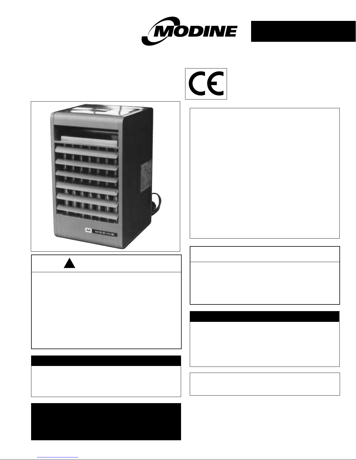
installation and service manual
gas-fired unit heaters
models PDE
G20, G31
6-592
55HH7755004477AA
CCoonntteennttss
Pages
Inspection on arrival..............................................................1
Special precautions ..............................................................2
General introduction .............................................................3
Technical data....................................................................3-4
Installation .........................................................................4-6
Positioning heater..............................................................4
Ventilation..........................................................................5
Unit suspension.................................................................5
Flue system....................................................................5-6
Piping ................................................................................6
Gas supply........................................................................6
Electrical supply................................................................6
Commissioning .....................................................................7
Servicing...............................................................................8
Wiring Diagram.....................................................................9
Major Component Location ..................................................9
Replacement of parts .........................................................10
Fault finding........................................................................11
Spare parts list ..............................................................11-12
WARNING
IImmpprrooppeerr iinnssttaallllaattiioonn,, aaddjjuussttmmeenntt,,
aalltteerraattiioonn,, sseerrvviiccee oorr mmaaiinntteennaannccee ccaann ccaauussee
pprrooppeerrttyy ddaammaaggee,, iinnjjuurryy oorr ddeeaatthh,, aanndd ccoouulldd
ccaauussee eexxppoossuurree ttoo ssuubbssttaanncceess wwhhiicchh hhaavvee
bbeeeenn ddeetteerrmmiinneedd bbyy vvaarriioouuss aaggeenncciieess ttoo
ccaauussee ccaanncceerr,, bbiirrtthh ddeeffeeccttss oorr ootthheerr
rreepprroodduuccttiivvee hhaarrmm.. RReeaadd tthhee iinnssttaallllaattiioonn,,
ooppeerraattiinngg aanndd mmaaiinntteennaannccee iinnssttrruuccttiioonnss
tthhoorroouugghhllyy bbeeffoorree iinnssttaalllliinngg oorr sseerrvviicciinngg tthhiiss
eeqquuiippmmeenntt..
FFOORR YYOOUURR SSAAFFEETTYY
IIff yyoouu ssmmeellll ggaass::
11.. OOppeenn wwiinnddoowwss
22.. DDoonn''tt ttoouucchh eelleeccttrriiccaall sswwiittcchheess..
33.. EExxttiinngguuiisshh aannyy ooppeenn ffllaammee..
44.. IImmmmeeddiiaatteellyy ccaallll yyoouurr ggaass ssuupppplliieerr..
FFOORR YYOOUURR SSAAFFEETTYY
TThhee uussee aanndd ssttoorraaggee ooff ggaassoolliinnee oorr ootthheerr
ffllaammmmaabbllee vvaappoouurrss aanndd lliiqquuiiddss iinn ooppeenn
ccoonnttaaiinneerrss iinn tthhee vviicciinniittyy ooff tthhiiss aapppplliiaannccee iiss
hhaazzaarrddoouuss..
THIS MANUAL IS THE PROPERTY OF THE OWNER.
PLEASE BE SURE TO LEAVE IT WITH THE OWNER WHEN
YOU LEAVE THE JOB.
!
TToo pprreevveenntt pprreemmaattuurree hheeaatt eexxcchhaannggeerr ffaaiilluurree
ddoo nnoott iinnssttaallll AANNYY ggaass ffiirreedd uunniittss iinn aarreeaass
wwhheerree cchhlloorriinnaatteedd,, hhaallooggeennaatteedd oorr aacciidd vvaappoouurrss
aarree pprreesseenntt iinn tthhee aattmmoosspphheerree..
IInnssppeeccttiioonn oonn AArrrriivvaall
1. Inspect unit upon arrival. In case of damage, report
immediately to transportation company , and y our local sales
representative.
2.
Inspect unit received for conformance with description of
product ordered.
IMPORTANT
TThhee uussee ooff tthhiiss mmaannuuaall iiss ssppeecciiffiiccaallllyy iinntteennddeedd
ffoorr aa qquuaalliiffiieedd iinnssttaallllaattiioonn aanndd sseerrvviiccee aaggeennccyy..
AAllll iinnssttaallllaattiioonn aanndd sseerrvviiccee ooff tthheessee uunniittss mmuusstt
bbee ppeerrffoorrmmeedd bbyy aa qquuaalliiffiieedd iinnssttaallllaattiioonn aanndd
sseerrvviiccee aaggeennccyy..
August, 1999
0120

22
TTHHEE IINNSSTTAALLLLAATTIIOONN AANNDD MMAAIINNTTEENNAANNCCEE IINNSSTTRRUUCCTTIIOONNSS
IINN TTHHIISS MMAANNUUAALL MMUUSSTT BBEE FFOOLLLLOOWWEEDD TTOO EENNSSUURREE SSAAFFEE,,
EEFFFFIICCIIEENNTT AANNDD TTRROOUUBBLLEE-FFRREEEE OOPPEERRAATTIIOONN.. IINN
AADDDDIITTIIOONN,, PPAARRTTIICCUULLAARR CCAARREE MMUUSSTT BBEE EEXXEERRCCIISSEEDD
RREEGGAARRDDIINNGG TTHHEE SSPPEECCIIAALL PPRREECCAAUUTTIIOONNSS LLIISSTTEEDD BBEELLOOWW..
FFAAIILLUURREE TTOO PPRROOPPEERRLLYY AADDDDRREESSSS TTHHEESSEE CCRRIITTIICCAALL
AARREEAASS CCOOUULLDD RREESSUULLTT IINN PPRROOPPEERRTTYY DDAAMMAAGGEE OORR LLOOSSSS,,
PPEERRSSOONNAALL IINNJJUURRYY,, OORR DDEEAATTHH..
1. Any power supply must be disconnected before making
wiring connections to prevent electrical shock and
equipment damage. All units must be wired strictly in
accordance with the wiring diagram (see Fig. 6 page 9).
2. The gas supply must be turned off before commencing
installation of the heaters. An isolating union gas cock or
union and isolating gas cock
MMUUSSTT
be fitted before the inlet
to the gas valve to allow replacement of parts.
3. The gas supply pressure to the unit heater controls must
never exceed 45mbar.
When leak testing the gas supply system, the unit, and its
combination gas control, must be isolated during any
pressure testing in excess of 45mbar. The unit should be
isolated from the gas supply system by closing the manual
shutoff valve.
4. Start-up and adjustment procedures should be performed
by a qualified engineer.The gas inlet pressure should be
checked upstream of the combination gas control.The inlet
pressure should be at least 20mbar on natural gas or 37mbar
on propane.Purging of gas piping should be perf ormed as
described in IM2. Supply pressure and setting pressure must
be checked with heater in operation when making final
adjustments.
5. All units must be flued to outside.
6. The units
MMUUSSTT NNOOTT bbee
installed in potentially explosive or
flammable atmospheres laden with grain dust, sawdust or
similar airborne materials.
7. Installation of units in high humidity or salt water
atmospheres should be avoided as this will cause
accelerated corrosion resulting in a reduction of the normal
life span of the units.
8. To prevent premature heat exchanger failure do not locate
AANNYY
gas fired unit in areas where chlorinated, halogenated
or acid vapours are present in the atmosphere.
9. Do not install units in extremely draughty locations.
Draughts can cause burner flames to impinge on the heat
exchanger thereby shortening its life.Separation between
units should be maintained to avoid discharge from one unit
entering the inlet of another.
10. Do not install units in tightly sealed rooms or small
compartments without provision for adequate combustion
air and venting. Combustion air must have access to the
space through a minimum of two permanent openings in
the enclosure, one near the bottom and the other near the
top.They should provide a free area of at least the values
given in Section 2.2 ‘Ventilation’.
11. Do not install units outdoors
12. For all sizes, required minimum clearance to combustible
materials from the bottom of the unit is 300mm (however
see page 2 section 16 which may require greater
clearances for servicing) and from the sides 450mm. For
PDE units sizes 30-50 minimum clearance from the top is
25mm and from the flue collar 50mm; for PDE units sizes
75-300 minimum clearance from the top is 50mm and from
the flue collar is 75mm; for PDE unit 350 minimum
clearance from the top is 75mm and from the flue collar is
100mm, for PDE unit 400 minimum clearance from the top
is 100mm and from the flue collar is 125mm.
13. At least 150mm clearance at the sides and 300mm
clearance at rear (or 150mm beyond end of motor at rear of
unit, whichever is greater) must be allowed to provide
sufficient air for combustion and correct operation of the
fan.However see page 2 section 12 for clearances to
combustible material.
14. The minimum distance required from combustible materials
is based on the combustible material surface not exceeding
70°C.Clearance from the top of the unit may be required to
be greater than 150mm if heat damage, other than fire,
may occur to materials above the unit heater at the
temperature described.
15. PDE unit heaters are designed for use in heating
applications with ambient temperatures between 0°C
and 32°C.If an application exists where ambient
temperatures can be expected to fall outside of this range,
contact your local sales representative for
recommendations.
16. Clearance must be provided for opening hinged bottom for
servicing. See Figure 1. Do not stand unit on its base.
17. To ensure that flames do not impinge on heat exchanger
surfaces, the unit must be suspended in a ver tical and level
position. Failure to suspend a unit properly may shorten its
life.
18. The unit heater must not be lifted by its gas controls or gas
manifold.
19. Ensure there are no obstructions which block air intake and
discharge of the unit heater.
20. Do not attach duct work or air filters to any PDE model unit
heaters.
21. In aircraft hangars, the bottom of the unit must be at least
3m from the highest surface of the wings or engine
enclosures of the highest aircraft housed in the hangar and
the installation must be in accordance with the
requirements of the enforcing authority.
22. In garages or other sections of aircraft hangars such as
offices and shops which communicate with areas used for
servicing or storage, the bottom of the unit must be at least
1.8m above the floor.
23. The piping, electrical, ventilation and flueing instructions in
this manual should be carefully read before commencing
installation.
24. All literature shipped with the unit should be kept for future
use for servicing or service diagnosis. None of the literature
shipped with the unit should be discarded.
25. Only approved service replacement parts should be used
when servicing or repairing these unit heaters. A complete
replacement parts list may be obtained by contacting your
appliance supplier.The data plate on the unit gives the unit
model number, serial number and company address. Any
substitution of non-approved parts or controls is at the
owners risk and may invalidate the EC Certification.
26. Always turn off the gas supply at the gas cock and
disconnect the electricity supply to the appliance before
servicing or replacing any components.
27. These unit heaters will normally be controlled by a room
thermostat. Harry Taylor have available a proportional
temperature controller (PTC-1) which can be used to
provide this control. If a room thermostat is to be used
contact Harry Taylor for details of suitable models.
IINNSSTTAALLLLAATTIIOONN
SSPPEECCIIAALL PPRREECCAAUUTTIIOONNSS
33
These instructions are for the PDE unit set up as a Category
I
2H
heater to use natural gas (G20) at a nominal supply
pressure of 20mbar.This is one of its many CE certified forms.
Information on the PDE unit set up as a Catergory I
3+
heater to
use propane (G31) at a nominal suppy pressure of 37mbar,
another certified form, is given in Table 4, page 12.
HHeeaatteerrss
mmuusstt nnoott uussee ggaasseess ootthheerr tthhaann tthhoossee ffoorr wwhhiicchh tthheeyy wweerree
ddeessiiggnneedd aanndd bbuuiilltt..
These instructions should be read thoroughly before
commencing installation of the appliance.
It is the law that all gas appliances are installed by competent
persons, e.g. CORGI Registered, in accordance with the Gas
Safety (Installation and Use) Regulations 1984 (As Amended).
Failure to install the appliance correctly could lead to
prosecution and it is therefore in your interest, and that of
safety, to ensure the law is complied with.
The installation of the appliance must be in accordance with
the current I.E.E. Regulations (BS 7671), and relevant
requirements of the local gas region, local authority, British
Standard Codes of Practice and Building Regulations.
SSeeee aallssoo::
BS 6891 Installation of Low Pressure Pipework.
BS 6230 Installation of Gas Fired Forced Convection Air
Heaters for Commercial and Industrial Space Heating.
BBrriittiisshh GGaass PPuubblliiccaattiioonnss::
IM 2 Purging Procedures of Non-Domestic Gas Boilers.
IM 5 Soundness Testing Procedures for Non-Domestic Gas
Installations.
IM 11 Flues for Commercial and Industrial Gas Fired Boilers
and Air Heaters.
IM 16 Guidance Notes for the Installation of Gas Pipework.
MMOODDIINNEE GGAASS FFIIRREEDD UUNNIITT HHEEAATTEERRSS PPDDEE MMOODDEELLSS
GGEENNEERRAALL IINNTTRROODDUUCCTTIIOONN
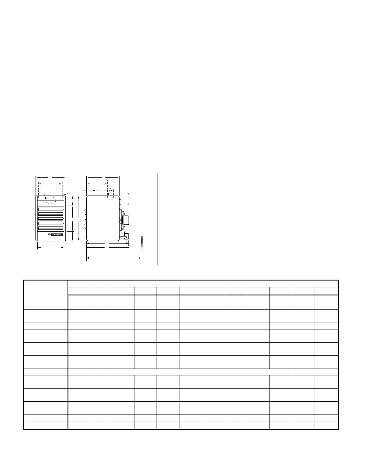
TTAABBLLEE 11..TTEECCHHNNIICCAALL DDAATTAA
A
H
D (OPENING)
BB
E
AA
B
K
W
X
F
C
K
G
L - Approx
MIN. DISTANCE
TO WALL IS L + 6"
J VENT PIPE
EE
(MIN. DISTANCE TO WALL)
L
LL
DDiimmeennssiioonnss ((mmmm))
DDiimmeennssiioonn MMooddeell NNuummbbeerr -PPDDEE
SSyymmbbooll 3300 5500 7755 110000 112255 115500 117755 220000 225500 330000 335500 440000
AA
327 438 438 489 489 533 597 651 651 727 854 1,016
BB
616 616 730 730 895 895 895 1,022 1,022 1,022 1,022 1,022
CC
375 375 508 508 559 559 559 635 635 635 635 635
DD
265 376 376 427 427 472 535 589 589 665 792 953
EE
330 330 406 406 508 508 508 610 610 610 610 610
FF
235 235 279 279 305 305 305 343 343 356 ––
GG
51 51 70 70 92 92 92 111 111 111 108 108
HH
235 346 346 397 397 448 505 559 559 635 762 924
AAAA
127 127 159 159 203 203 203 229 229 229 229 229
BBBB
159 159 165 165 184 184 184 184 184 184 184 184
JJ ((IInncchheess))
3" 4" 5" 6" 6" 7" 7" 7" 8" 9" 10" 10"
KK
11
M10
GGaass CCoonnnn.. ""
1/2 1/2 1/2 1/2 1/2 1/2 1/2 1/2 1/2 3/4 3/4 3/4
WW
––––––– –––127 127
XX
––––––– –––406 406
LL
22
718 718 914 914 927 943 943 1,038 1,041 1,073 1,073 1,200
LLLL
448 457 590 599 650 669 699 775 775 797 797 797
EEEE
565 565 737 737 775 775 775 835 835 835 835 835
FFaann DDiiaammeetteerr
228 305 305 348 348 408 458 508 508 560 560 650
AApppprrooxx.. WWeeiigghhtt ((kkgg))
26.4 32.7 46.4 52.7 69.1 73.6 76.8 105 105 118.6 150 186.4
1
PDE30 to PDE300 inclusive - 2 holes (and the level hanging adjustment feature). PDE350 and PDE400 - 4 holes.
2
Dimension equals overall plus 150mm.
NNOOTTEE:: NNOOTT AALLLL MMOODDEELLSS AARREE AAVVAAIILLAABBLLEE IINN TTHHEE UUKK.. CCHHEECCKK WWIITTHH YYOOUURR SSUUPPPPLLIIEERR..
DDIIMMEENNSSIIOONNSS PPEERRFFOORRMMAANNCCEE —— PPDDEE
44
IINNSSTTAALLLLAATTIIOONN
22..11 PPoossiittiioonniinngg UUnniitt HHeeaatteerrss
When siting units, consider general spaceheating requirements,
availability of gas, and proximity to flue locations. Unit heaters
should be positioned so heated air streams wipe exposed walls
without blowing directly against them.In multiple unit
installations, arrange units so that each supports the air stream
from another, setting up circulatory air movement in the area,
but maintain separation between units so discharge from one
unit will not be directed into the inlet of another.In buildings
exposed to prevailing winds, a large portion of the heated air
should be directed along the windward wall.Avoid interference
to air streams as much as possible.Mounting height (measured
from bottom of unit) at which unit heaters are installed is critical.
Maximum mounting heights are listed in the Table 1 on page 3.
The maximum mounting height for any unit is that height above
which the unit will not deliver heated air to the floor. The
maximum mounting heights must not be exceeded in order to
ensure maximum comfort. PDE unit heaters are designed for
use in heating applications with ambient temperatures between
O°C and 32°C.If an application exists where ambient
temperatures can be expected to fall outside this range, contact
your local sales representative for recommendations.
CAUTION
Units must not be installed in potentially explosive,
flammable, or corrosive atmosphere. To prevent premature
heat exchanger failure do not locate ANY gas fired unit in
areas where chlorinated, halogenated or acid vapours are
present in the atmosphere.
!
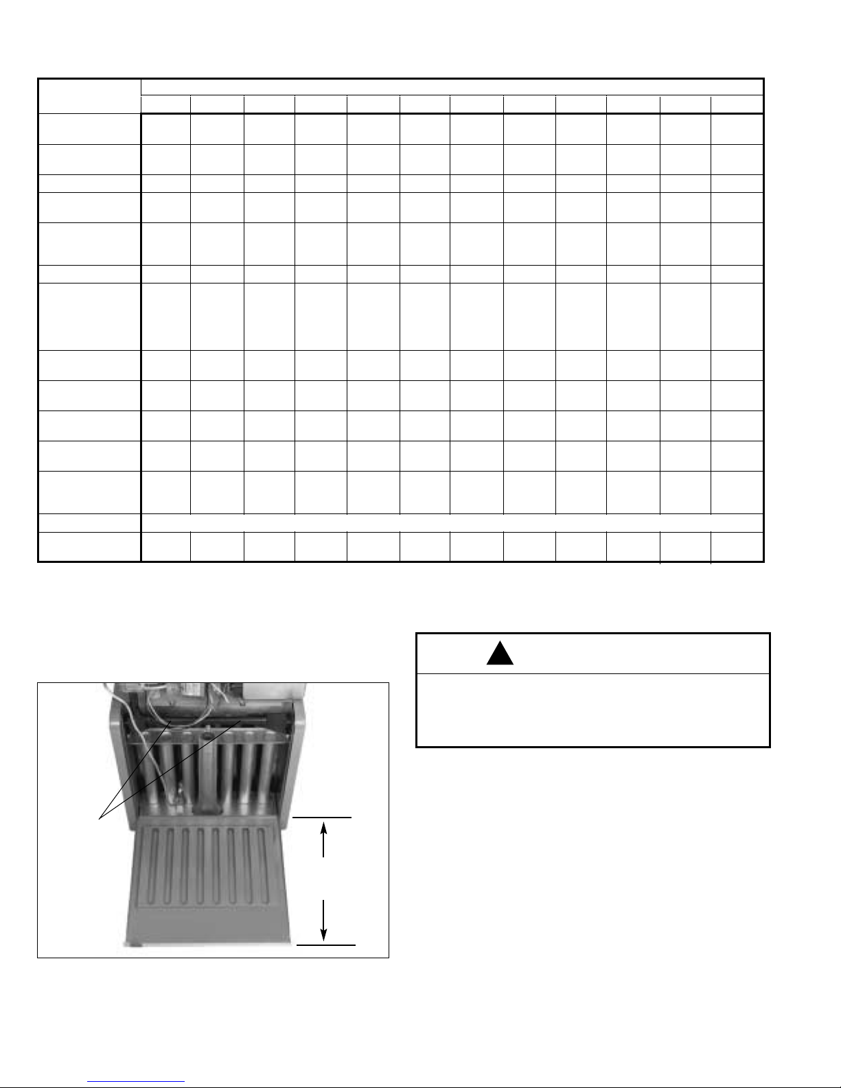
FFiigguurree 11
HHiinnggeedd BBaassee ffoorr SSeerrvviicciinngg
(See Dimension "C", page 3)
WING SCREWS
THAT SECURE
HINGED
BOTTOM
THIS IS
DIMENSION C,
SEE PAGE 3
PPeerrffoorrmmaannccee —— nnaattuurraall ggaass oonnllyy.. SSeeee ppaaggee 1122 ffoorr pprrooppaannee ddeettaaiillss..
*
Based on natural gas - typical calorific value 37.78 MJ/M3.
**
At 18°C ambient and unit fired at full-rated input. Mounting height as measured from bottom of unit.
NNOOTTEE:: NNOOTT AALLLL MMOODDEELLSS AARREE AAVVAAIILLAABBLLEE IINN TTHHEE UUKK.. CCHHEECCKK WWIITTHH YYOOUURR SSUUPPPPLLIIEERR..
TTAABBLLEE 22
MMooddeell NNuummbbeerr-PPDDEE
3300 5500 7755 110000 112255 115500 117755 220000 225500 330000 335500 440000
HHeeaatt IInnppuutt
((ggrroossss)) kkWW**
8.8 14.7 22.0 29.3 36.6 44.0 51.3 58.6 73.3 87.9 102.6 117.2
HHeeaatt IInnppuutt
((nneett)) kkWW**
7.9 13.2 19.8 26.4 32.6 39.6 46.2 52.7 66.0 79.1 92.3 105.5
OOuuttppuutt kkWW**
7.0 11.7 17.6 23.4 29.3 35.1 41.0 46.9 58.6 70.3 82.0 93.8
BBuurrnneerr sseett..
7.0 6.7 6.8 6.7 6.5 6.1 5.7 7.1 5.5 7.2 6.5 6.4
pprreessss.. mmbbaarr
IInnjjeeccttoorr - NNoo..
111222333456
DDiiaamm.. mmmm
2.71 3.45 4.30 3.45 3.91 4.30 3.86 3.86 4.7 4.22 4.22 4.09
MMaarrkkiinngg
36 29 18 29 23 18 24 24 13 19 19 20
GGaass rraattee mm33//hh
0.82 1.36 2.04 2.72 3.39 4.08 4.76 5.43 6.8 8.15 9.51 10.87
AApppprrooxx.. fflluuee
9 14 21 29 36 43 50 57 71 86 100 114
ggaass vvooll.. iinn
sseeccoonnddaarryy fflluuee**
33..77%% CCOO22&&
110000°°CC 11//sseecc
AAiirr ffllooww
0.21 0.35 0.51 0.69 0.87 1.03 1.20 1.36 1.75 2.10 2.34 2.66
mm33//sseecc
OOuuttlleett vveelloocciittyy
2.6 3.2 3.7 4.3 4.4 4.7 4.8 4.1 5.3 5.7 5.6 5.3
mm//sseecc
AAiirr TTeemmpp rriissee
27 27 28 27 27 28 28 28 27 27 28 28
°°CC
MMoouunnttiinngg hhtt..
2.1 2.7 3.7 4.3 4.3 4.9 5.2 4.6 5.8 6.4 6.1 6.7
((mmaaxx)) mm
HHeeaatt tthhrrooww
7.6 10.1 12.5 14.9 15.5 16.8 18.0 15.5 20.4 22.6 21.9 23.2
((aatt mmaaxx mmoouunntt.. hhtt..))
mm****
PPoowweerr ssuuppppllyy
230V 50Hz
PPoowweerr uussee
125 150 200 225 400 450 450 400 750 850 950 1,200
((wwaattttss))

55
Safe, efficient and trouble free operation of conventionally flued
appliances is vitally dependent on the provision of an adequate
supply of fresh air to the room in which the appliance is installed.
In buildings having a design air change rate of less than 0.5/h,
and where indirect fired heaters are to be installed in heated
spaces having volume less than:
(a) 4.7 m
3
per kilowatt of total rated heat input for heaters
fitted with natural draught burners: or
(b) 2.2 m
3
per kilowatt of total rated heat input for heaters
fitted with forced or induced draught burners;
grilles shall be provided at low level (i.e. below the level
of the appliance flue connection); except that:
(1) for heaters of heat input less than 60 kW, the total
minimum free area shall be not less than 4.5 cm
2
per
kilowatt of rated heat input;or
(2) for heaters of heat input 60 kW or more, the total mini-
mum free area shall not be less than 270 cm
2
plus 2.25
cm
2
per kilowatt in excess of 60 kW rated heat input.
Most traditional building constructions will provide air changes
of at least 0.5/h without the need for ventilation openings. In the
case of a building having an air change rate less than 0.5/h, low
level ventilation will be necessary.
For indirect heaters installed in buildings with a design air
change rate of 0.5/h or greater, and where the volume of the
heated space is greater than 4.7 m
3
per kilowatt of total rated
heat input, as appropriate, additional high and low level
ventilation will not be required.
22..33 UUnniitt SSuussppeennssiioonn
The most common method of hanging PDE unit heaters is to
utilize M10 threaded rod. On each piece of threaded rod used,
screw a nut about 25mm onto the end of the rods that will be
screwed into the unit heater. Then put a washer over the end of
the threaded rod and screw the rod at least 5 turns, and no
more than 10 turns, into the weld nuts on the top of the heater.
Tighten the nut first installed onto the threaded rod to prevent it
from turning. Drill holes into a steel channel or angle iron at the
same centreline dimensions as the heater that is being installed.
The steel channels or angle iron pieces need to span and be
fastened to appropriate structural members.Cut the threaded
rods to the preferred length, push them through the holes in the
steel channel or angle iron and secure with washers and lock
nuts or lock washers and nuts.A double nut arrangement can be
used here instead of at the unit heater (a double nut can be
used at both places but is not necessary).The entire means of
suspension must be adequate to support the weight of the unit
(see page 3 for unit weights).
For proper operation, the unit must be installed in a level
horizontal position. Clearances to combustibles as specified
below must be strictly maintained.The heaters must not be
installed above the maximum mounting height shown in Table 2
on page 4.
On all units, except the PDE 350 and PDE 400, two M10
tapped holes are located in the top of the unit to receive
threaded rods.
Units with two point suspension, models PDE30 to PDE300,
incorporate a level hanging feature.
PDE30 to PDE300 units that do not hang level after being
installed, can be corrected in place. Remove both outer side
panels (screws are on back flange of side panel) exposing the
(adjustable) mounting brackets (Fig.2).Loosen the set screws
holding the mounting brackets in place and using a rubber
mallet or something similar, tap the heater into a position where
it does hang level.Tighten set screws and replace the outer
side panels.
The PDE 350 and PDE 400 have four mounting holes in the top
of the unit.
TToo eennssuurree tthhaatt ffllaammeess aarree ddiirreecctteedd iinnttoo tthhee cceennttrree ooff tthhee hheeaatt
eexxcchhaannggeerr ttuubbeess,, tthhee uunniitt mmuusstt bbee ssuuppppoorrtteedd iinn aa vveerrttiiccaall
ppoossiittiioonn,, wwiitthh ssuussppeennssiioonn hhaannggeerrss ““UUPP””..
CChheecckk wwiitthh aa lleevveell..
This is important to the operation and life of the unit.
22..44 FFlluuee SSyysstteemm
To ensure safe and satisfactory operation of the heater, the flue
system must be capable of the complete evacuation of flue
products at all times.The height of the flue ter minal above the
draught diverter must be at least 2m and for this height no more
than 0.6m horizontal run may be installed immediately after the
appliance outlet. For greater heights 0.3m horizontal run may be
added for each extra metre of flue height.
The chimney must terminate in a downdraught free zone.
Compliance with the recommendations made in BS.6644;
British Gas publication IMII Flues for Commercial and Industrial
Gas fired boilers and gas heaters’ and the ‘Third Edition of the
1956 Clean Air Memorandum’ should be strictly observed
where applicable.
The flue/chimney design should avoid the formation of excessive
quantities of condensate and for this reason it is recommended
that all chimneys are suitably insulated and lined.
Drain points should be fitted at the bottom of all vertical flue
sections. Drain pipes must be a minimum of 25mm internal
diameter and manufactured from acid condensate resistant
materials (e.g. stainless steel) and positioned so that pipe runs
and discharge points are not subject to the effects of frost and
that flue gases cannot leak into the room.
Any terminal fitted must be an approved type.
22..22 VVeennttiillaattiioonn
CAUTION
For all sizes, required minimum clearance to combustible
materials from the bottom of the unit is 300mm (but see
2.1.16) and from the sides 450mm. For PDE units sizes
30-50 minimum clearance from the top is 25mm and from
the flue collar 50mm; for PDE units sizes 75-300 minimum
clearance from the top is 50mm and from the flue collar is
75mm; for PDE unit 350 minimum clearance from the top is
75mm and from the flue collar is 100mm; for PDE unit 400
minimum clearance from the top is 100mm and from the flue
collar is 125mm. Allow at least 300mm clearance at the rear
or 150mm beyond the end of motor (whichever is greater) to
provide sufficient air for combustion and correct operation of
the fan.Provide clearance for opening at the hinged bottom
for servicing. See Figure. 1.
!
FFiigguurree 22
AAddjjuussttaabbllee MMoouunnttiinngg BBrraacckkeettss
Remove side panels to adjust
mounting brackets
CAUTION
PDE unit heaters must be flued to outside – do not operate
without a flue. A built in draught diverter is fitted – additional
external draught diverters are not required or permitted.
!

66
Do not use a flue smaller than the flue pipe connection on the
unit. Flue should be stainless steel, aluminum or other suitable
corrosion resistant material.
Install with a minimum upward slope from unit of 20mm per
metre and suspend securely from overhead structure at points
no greater than 1 metre apart. For best flue operation, install
the vertical flue as close to the unit as possible. Avoid running
flue through unheated space when possible.When it does pass
through an unheated space, it is recommended that double
walled flue pipe is used. If single wall is used, insulate runs of
greater than 1.5m to minimize condensation. Use insulation that
is noncombustible with a rating of not less than 200°C.
Keep single wall flue pipe at least 150mm from combustible
material (see page 2 section 12 for permissible reductions). For
double wall pipe maintain clearances listed in manufacturer’s
literature.The minimum distance from combustible material is
based on the combustible material surface not exceeding 70°C.
Clearance from the flue connector, or top of unit may be
required to be greater than the minimum clearance if heat
damage other than fire (such as material distortion or
discoloration) may occur. Where the flue passes through a
combustible floor or roof, a metal sleeve 100mm greater than
the flue diameter is necessary.If there is 2m or more of flue
pipe in the open space between the unit and where the flue
pipe passes through the floor or roof, the sleeve need only to be
50mm greater than the diameter of the flue pipe. If a sleeve is
not used, all combustible material must be cut away to provide
the specified clearance to combustibles.Any material used to
close the opening must be noncombustible.
The top of the vertical flue should extend at least 600mm above
the highest point where it passes through a roof and at least
600mm higher than any portion of a building within a horizontal
distance of 3m (see Figure 3).
Use a flue terminal to reduce downdraughts and moisture in the
flue.
Check flue system to see that combustion products are being
satisfactorily cleared. Operate unit for several minutes and then
pass a lighted match around the edge of the diverter relief
opening. If the flame is drawn into the opening, the system is
drawing properly. If not, make adjustments to provide adequate
draught.
AADDDDIITTIIOONNAALL RREEQQUUIIRREEMMEENNTTSS FFOORR FFLLUUEEIINNGG IINNTTOO AANN
EEXXIISSTTIINNGG MMAASSOONNRRYY CCHHIIMMNNEEYY
In the case of brick or similar structures a stainless steel rigid or
flexible flue liner (grade 304/316) may be used in conjunction
with a 50mm (minimum) thick layer of vermiculite or perlite
granules between the liner and the inner skin of the chimney
body. Liners should be sealed at both the top and the bottom.
In situations where a conventional flue is inappropriate, a flue
boost kit is available for all PDE models allowing up to 10
metres (or equivalent length) of horizontal flue.
22..55 PPiippiinngg
22..66 GGaass SSuuppppllyy
If there is any doubt regarding the capacity of the gas meter,
the available gas pressure, the adequacy of existing service
pipes or the size required for new service pipes then the advice
of the gas supplier should be requested. Installation pipework
should be fitted and tested for gas soundness in accordance
with BS. 6891 for small installations or IGEUP1 and IGEUP2 for
large installations.
The local gas supplier must be consulted if it is necessary to
employ a gas pressure booster.
An isolating union gas cock or union and isolating gas cock
MMUUSSTT
be fitted before the inlet to the gas valve to allow
replacement of parts.
Before installation, check that the local distribution conditions,
nature of gas and pressure, and the current state of adjustment
of the appliance are compatible.
22..77 EElleeccttrriiccaall SSuuppppllyy
A 230V~50 Hz mains supply is required, fused at 5 amps
(PDE 350 and 400 10 amps).
Wiring external to the appliance
MMUUSSTT
be in accordance with
I.E.E. (BS. 7671) Wiring Regulations and any local regulations
which apply.
The mains wiring to the appliance must be fixed, PVC insulated
and the wires should be between 1 and 2.5 mm
2
cross sectional
area.
The mains wiring inlet to the junction box is in the base of the
box and the installer MUST fit a suitable strain relief bush to this
hole.
CAUTION
Gas pressure to unit heater controls must never exceed
45mbar.
When leak testing the gas supply system, the appliance and
its combination gas control must be isolated during any
pressure testing in excess of 45mbar. The appliance should
be isolated from the gas supply system by closing the inlet
manual shutoff valve.
!
FFiigguurree 33
UUnniitt HHeeaatteerr IInnssttaallllaattiioonn
CAUTION
Disconnect power supply before making wiring connections
to prevent electrical shock and equipment damage.ALL
UNITS MUST BE WIRED STRICTLY IN ACCORDANCE
WITH WIRING DIAGRAM SUPPLIED WITH HEATER. ANY
WIRING DIFFERENCE FROM WIRING DIAGRAM MAY BE
HAZARDOUS TO PERSONS AND PROPERTY.
TTHHIISS AAPPPPLLIIAANNCCEE MMUUSSTT BBEE CCOORRRREECCTTLLYY EEAARRTTHHEEDD..
!
3.5m MIN.
TO WALL OR ADJOINING BUILDING
APPROVED
TERMINAL
1 METER*
MIN.
ROOF FLASHING
USE THIMBLE
THROUGH CEILING
DRIP LEG WITH
UNIT
.635cm
SLOPE TO
30.5cm
*SIZE ACCORDING TO EXPECTED SNOW DEPTH.
CLEANOUT CAP

77
Before commencing commissioning:
Ensure that the electrical supply is off.
Extinguish all naked lights and open all doors and windows.
DDOO
NNOOTT SSMMOOKKEE
. Check that the gas supply is turned on at the
meter and that the main gas cock is open. Loosen the union
and allow air to be purged from the gas line until gas is
smelled.Tighten the union.See BS 6891 and/or IM 2 for fur ther
details.Turn off the gas supply and connect a manometer to the
test point at the outlet of the combination gas control.Tur n on
the gas supply. Check for gas soundness.
33..11 PPrree-ooppeerraattiioonnaall CChheecckkss
Although this unit has been assembled and fired at the factory,
the following pre-operational procedures should be performed to
ensure correct on site operation:
Check burner for alignment.
Check fan clearance.Fan should not contact casing when spun
by hand.
Check all electrical connections to ensure they are secure.
Check that all horizontal deflector blades are open a minimum of
30° as measured from vertical.
33..22 LLiigghhttiinngg IInnssttrruuccttiioonnss
3.2.1. Set room thermostat to lowest setting
3.2.2. Drop down the bottom pan (see 4.1.1 page 8).Set gas
control knob to PILOT and push in while lighting the pilot
with gas match or taper.
Hold in for 1/2 minute after pilot is lit.
3.2.3. Check pilot flame adjustment.The pilot burner is fitted with
an injector such that it will operate correctly with an inlet
pressure of 15-20 mbar on natural gas and 37mbar on
propane but final adjustment must be made after
installation. Adjust to have a soft steady flame 20-25mm
long and encompassing 8 to 12mm of the tip of the
thermocouple. Normally this flame will produce satisfactory
results.To adjust flame use the pilot adjustment screw on
combination gas control (for location, see Figure 4).
If the pilot flame is longer and larger than shown by Figure
5 it is possible that this will cause soot and/or impinge on
the heat exchanger causing burnout.If the pilot flame is
shorter than shown it may cause poor ignition and result in
the controls not opening the combination gas control. A
short flame can be caused by a dirty pilot injector. Pilot
flame condition should be observed periodically to ensure
trouble free operation.
3.2.4. Move gas control knob to ON.
3.2.5. Set room thermostat to desired setting.
3.2.6. Check gas piping for leaks as described in IM 5.
3.2.7. Check gas input rate by measuring burner pressure using
the manometer fitted to test point at the outlet of the
combination gas control. Allow unit to operate for 15
minutes to stabilize.Check the pressure and if necessary
adjust to the figure shown in Table 2 on page 4 for the
particular model. The location of the pressure setting
adjuster on the combination gas is shown in Figure 4.
Remove the dust cover over the adjuster and, using a
small screwdriver turn the screw beneath clockwise to
increase and anti-clockwise to decrease the pressure.
Allow the unit to operate for 15 minutes then check the
pressure again. Replace the dust cover when finished.
Disconnect the manometer from the test point and replace
the sealing screw in the pressure test nipple.
33..33 CCoonnttrrooll OOppeerraattiinngg SSeeqquueennccee
With pilot alight, when the thermostat calls for heat, power is
supplied to the combination gas control and at the same time
power is supplied to the fan timer.The main burner should light
immediately.The fan motor will start in 15 to 45 seconds.When
the thermostat has been satisfied, power is turned off to the
combination gas control and fan timer. The main burner will go
out but the pilot will continue to burn.The fan motor will continue
to operate for 45 to 75 seconds to allow the heat exchanger to
cool down.
FFiigguurree 55
PPiilloott FFllaammee AAddjjuussttmmeenntt
33.. CCOOMMMMIISSSSIIOONNIINNGG
FFiigguurree 44
CCoommbbiinnaattiioonn GGaass CCoonnttrrooll
20/25mm
CAUTION
Start-up and adjustment procedures should be performed by
a qualified engineer.
!
CAUTION
Important – Supply pressure and setting pressure must be
checked with heater in operation when making final adjustments.
!
GAS CONTROL KNOB
INLET PRESSURE
TEST FITTING
PRESSURE REGULATOR
ADJUSTMENT SCREW
(UNDER CAP SCREW)
INLET
PILOT TUBING
PILOT ADJUSTMENT
SCREW
THERMOCOUPLE / INTERRUPTER
CONNECTION
PROTECTIVE COVER
OUTLET
OUTLET
PRESSURE
TEST
FITTING

88
It is recommended that a full service be carried out at least
once a year by a qualified heating engineer (CORGI
Registered).
44..11 CClleeaanniinngg tthhee HHeeaatteerr
44..11..11 MMaaiinn BBuurrnneerr
Lower bottom pan by removing wing screws on the unit base.
Disconnect pilot pipe, and thermocouple lead from multifunctional
control.
Remove the two burner retaining pins holding the burner
assembly in place.
IIMMPPOORRTTAANNTT:: DDoo nnoott aatttteemmpptt ttoo rreemmoovvee tthhee ggaass mmaanniiffoolldd ttoo
eeaassee rreemmoovvaall ooff tthhee bbuurrnneerr aass tthhiiss ccoouulldd sseerriioouussllyy aaffffeecctt tthhee
ccoorrrreecctt ooppeerraattiioonn ooff tthhee aapppplliiaannccee iiff iitt iiss nnoott rree-ppoossiittiioonneedd eexxaaccttllyy
aass iinntteennddeedd.. TThhee aasssseemmbbllyy ccaann nnooww bbee lloowweerreedd ffrroomm tthhee uunniitt..
NNOOTTEE:: OOnn rreeffiittttiinngg tthhee bbuurrnneerr aasssseemmbbllyy eennssuurree tthhaatt tthhee sslloottss aatt
tthhee ffrroonntt ooff tthhee bbuurrnneerr aarree ccoorrrreeccttllyy llooccaatteedd oonn tthheeiirr sshhoouullddeerr
rriivveettss aanndd tthhaatt tthhee rreettaaiinniinngg ppiinnss aarree rreeffiitttteedd iinn tthhee ccoorrrreecctt
llooccaattiioonn..
Clean the burner ports (avoid using hard, sharp instruments
capable of damaging the ports) and check the injector (s) for
blockage.Clean carefully as necessary.
44..11..22 PPiilloott BBuurrnneerr
Inspect the pilot burner and thermocouple. Ensure they are clean
and in good condition.
CChheecckk::
(a) The pilot burner is securely fixed.
(b) The thermocouple tip is not burned or cracked.Replace if
necessary.
(c) The pilot burner head is undamaged.
(d) The pilot pipe/pilot connection is gastight.
44..11..33 HHeeaatt EExxcchhaannggeerr
After removing the burner assembly clean heat exchanger tubes
from bottom using a stiff brush
((nnoott wwiirree))
.
44..11..44 FFaann aanndd MMoottoorr
Remove fan guard.Check fan is securely fitted to motor shaft
and for damage to blades.Clean fan blades as necessary taking
care not to damage them.
NNOOTTEE:: EEnnssuurree aallll ffoouurr ffiixxiinnggss sslleeeevveess aarree ffiitttteedd bbeeffoorree rree-ffiixxiinngg
ffaann aass oovveerrttiigghhtteenniinngg ccoouulldd rreessuulltt iinn rreedduucceedd ffaann lliiffee..
44..11..55 GGeenneerraall
Check wiring for possible loose connections paying par ticular
attention to the overheat thermostat interrupter leads.
Check air louvres in bottom pan are clean and unobstructed.
Clean as necessary.
44..22 OOvveerrhheeaatt TThheerrmmoossttaatt
The overheat thermostat, bulb mounted on the left inner side
panel (when facing front of unit) – body in junction box, will shut
off the gas supply to the main burner in the event of overheating.
The manual reset button is located beneath a black screw off cap
positioned on the side of the junction box.See Figs.6 and 7.
It is a single pole single throw switch.The contacts open to shut
the combination gas control in the event of the unit overheating.
This overheat thermostat should operate only when something is
wrong with the unit.Whenever this thermostat operates, the
problem should be identified and corrected immediately or
serious damage may result. If the overheat thermostat cuts off
the gas supply during normal operation:
1. Make sure deflector blades are open and that there are not
any obstructions in the air inlet or discharge outlet.
2. Check actual input to unit against rated input.
3. Check motor is operating.
4. Check fan is not loose on motor shaft.
5. Check fan speed against motor data plate.
6. Check flue system is not damaged or blocked. Also check
unit is flued correctly and that there is not a negative
pressure in the building adversely affecting draught.
7. Clean heat exchanger tubes inside and out if necessary.
8. Check operation of fan delay timer.
9. If items 1 to 8 do not solve the problem, check overheat
thermostat and replace if necessary.
IIMMPPOORRTTAANNTT NNOOTTEE:: TThhee oovveerrhheeaatt tthheerrmmoossttaatt oonn tthhiiss uunniitt
hheeaatteerr wwiillll sshhuutt ooffff tthhee ggaass sshhoouulldd eexxcceessssiivvee ddiisscchhaarrggee
tteemmppeerraattuurreess ooccccuurr.. DDoo nnoott aatttteemmpptt ttoo ccoonnttrrooll tthhee ffaann wwiitthh tthhee
oovveerrhheeaatt tthheerrmmoossttaatt.. AAnnyy cchhaannggee iinn wwiirriinngg ttoo aatttteemmpptt ttoo ccoonnttrrooll
tthhee ffaann wwiitthh tthhee oovveerrhheeaatt tthheerrmmoossttaatt wwiillll rreessuulltt iinn hhaazzaarrddoouuss
ccoonnddiittiioonnss aanndd iinnvvaalliiddaattee tthhee wwaarrrraannttyy..
44..33 TTeessttiinngg aafftteerr SSeerrvviicciinngg
After re-assembly restore the electrical and gas supplies. Light
the appliance (see Lighting Instructions on inside of casing) and
check the gas connections for soundness as follows:
Close gas supply cock at the meter.
Remove the screw in the inlet pressure test point and connect a
manometer to the test nipple. Open the gas supply cock at the
meter and the appliance gas cock. Record the static pressure.
Close the gas supply cock at the meter and watch the pressure
gauge for approximately 3 minutes. Any decrease in pressure
(after the first minute of temperature stabilization) indicates a
gas leak which must be cured (first check connection of
manometer to test nipple).When satisfied remove manometer
and refit test nipple sealing screw.
44.. SSEERRVVIICCIINNGG
CAUTION
Always turn off the gas supply at the gas cock and
disconnect the electricity supply to the appliance before
servicing or replacing any components.
!

99
FFiigguurree 66
AAiirr HHeeaatteerr WWiirriinngg DDiiaaggrraamm
FFiigguurree 77
MMaajjoorr CCoommppoonneenntt LLooccaattiioonn
OVERHEAT
THERMOSTAT
BULB
LOUVRES
FFRROONNTT
VVIIEEWW
FLUE RELIEF
OPENING
SERIAL NUMBER
PLATE
FAN & MOTOR
DIMPLED HEAT
EXCHANGER
COMBINATION
GAS CONTROL
FAN MOTOR
CONDENSER
MANUAL RESET FOR
OVERHEAT
THERMOSTAT
BENEATH BLACK CAP.
JUNCTION
BOX
RREEAARR
VVIIEEWW
FLUE
CONNECTION
VVIIEEWW FFRROOMM BBEELLOOWW
((BBOOTTTTOOMM PPAANN OOPPEENN))
TAPPED MOUNTING
HOLES
Overheat Thermostat with
interupter to gas valve &
capillary with sensor to
heat exchanger
(Manual reset button
located beneath black
screw off cap)
230V Thermostat
(By Others on
installation)
230V/50 Hz
Supply
Gas Valve
Fan
Motor
TD Relay
Capacitor
Junction Box
CAUTION
FAILURE TO WIRE THIS UNIT ACCORDING
TO THIS WIRING DIAGRAM MAY RESULT
IN INJURY TO THE INSTALLER OR USER.
FOR DEVIATIONS CONTACT THE FACTORY.
MANIFOLD
MIXER
TUBES
BURNER
RETAINING PIN
MAIN
BURNER
ORIFICES
MANIFOLD MOUNTING
SCREW AND PIN

1100
TToo rreeppllaaccee::
55..11 BBuurrnneerr//ppiilloott//tthheerrmmooccoouuppllee
Lower bottom pan by removing wing screws on the unit base.
Disconnect pilot pipe, and thermocouple lead from multifunctional
control.
Remove the two burner retaining pins holding the burner
assembly in place.
IIMMPPOORRTTAANNTT:: DDoo nnoott aatttteemmpptt ttoo rreemmoovvee tthhee ggaass mmaanniiffoolldd ttoo
eeaassee rreemmoovvaall ooff tthhee bbuurrnneerr aass tthhiiss ccoouulldd sseerriioouussllyy aaffffeecctt tthhee
ccoorrrreecctt ooppeerraattiioonn ooff tthhee aapppplliiaannccee iiff iitt iiss nnoott rree-ppoossiittiioonneedd eexxaaccttllyy
aass iinntteennddeedd.. TThhee aasssseemmbbllyy ccaann nnooww bbee lloowweerreedd ffrroomm tthhee uunniitt..
NNOOTTEE:: OOnn rreeffiittttiinngg tthhee bbuurrnneerr aasssseemmbbllyy eennssuurree tthhaatt tthhee sslloottss aatt
tthhee ffrroonntt ooff tthhee bbuurrnneerr aarree ccoorrrreeccttllyy llooccaatteedd oonn tthheeiirr sshhoouullddeerr
rriivveettss aanndd tthhaatt tthhee rreettaaiinniinngg ppiinnss aarree rreeffiitttteedd iinn tthhee ccoorrrreecctt
llooccaattiioonn..
55..11..11 BBuurrnneerr
It is not possible to replace single burner bars.The complete burner
assembly must be replaced.Remove the pilot and thermocouple (see
5.1.2.) and refit to the new assembly.
55..11..22 PPiilloott
Remove the burner assembly as detailed above. Unscrew the
thermocouple. Undo the pilot bracket retaining the nut.The pilot gas pipe
can now be unscrewed (take care not to lose the pilot injector) and the
pilot assembly released by removing the two retaining screws. Replace
defective component and reassemble in reverse order.
55..22 TThheerrmmooccoouuppllee
Lower bottom pan by removing wing screws on the unit base.
The thermocouple can be unscrewed.
55..33 MMaaiinn BBuurrnneerr IInnjjeeccttoorr
Lower bottom pan by removing wing screws on the unit base.
The main injector can be unscrewed from the manifold and
replaced.
55..44 GGaass VVaallvvee
Disconnect pilot gas pipe, thermocouple and thermocouple
interrupter from the gas valve.
Remove green cover from the solenoid actuator on the valve
and detach flying leads from the terminal block, noting their
position.
Having ensured isolation of the gas supply uncouple the union
gas cock and unscrew the gas valve from the appliance inlet
gas pipe.
Replace gas valve and reassemble in reverse order.
55..55 TThheerrmmooccoouuppllee IInntteerrrruupptteerr
Unscrew thermocouple from top of gas valve and extract
thermocouple interrupter from the gas valve. Release spade
connections on interrupter cable from the overheat thermostat in
the heater junction box and feed back through the cable
grommet. Replace component and reassemble in reverse order.
55..66 DDeellaayy TTiimmeerr
The delay timer is located in the junction box.Remove the
junction box front cover by taking out the two retaining screws.
Remove the single retaining screw from beneath the junction
box, pull off the electrical connectors (taking care to note their
positions) and lift out the timer.Replace defective component
and reassemble in reverse order. If in doubt regarding the
electrical connections consult the wiring diagram on page 9.
55..77 OOvveerrhheeaatt TThheerrmmoossttaatt
The overheat thermostat body is located in the junction box.
Remove the junction box cover by taking out the two retaining
screws.Remove the thermostat cover retaining nut from the
outside of the junction box and pull back into the box. Remove
the left hand side casing of the heater (looking from the front)
by taking out the two retaining screws at the rear and pull the
side panel clear.The overheat thermostat bulb is mounted in the
air stream at the bottom left of the appliance. Remove the two
screws holding it in place and feed it back through the hole in
the inner casing.To refit remove the two lower front louvres
which can be sprung out.The thermostat bulb can now be
positioned and the retaining screws fitted.
55..88 FFaann//FFaann MMoottoorr//CCaappaacciittoorr
The capacitor is mounted alongside the junction box.Remove
the junction box front cover by taking out two retaining screws.
Disconnect the wires from the terminal block noting their
position.The capacitor retaining nut can be seen on the left hand
side of the junction box and should be removed.Replace the
defective component and reassemble in reverse order.If in doubt
regarding the electrical connections consult the wiring diagram
on page 9.
The fan/fan motor is mounted in the centre of the guard.Remove
the junction box front cover by taking out two retaining screws.
Disconnect the fan motor wires from the terminal block noting
their position and feed back through the grommet.Remove the
four guard mounting bolts and lift assembly clear.The fan and
motor can be removed from the guard by undoing the four bolts.
IIMMPPOORRTTAANNTT:: CCaarree mmuusstt bbee ttaakkeenn ttoo nnoottee iiff tthhee gguuaarrdd iiss
mmoouunntteedd oonn tthhee ffrroonntt oorr rreeaarr ffiixxiinngg ppooiinnttss ooff tthhee mmoottoorr.. IInnccoorrrreecctt
rree-aasssseemmbbllyy wwiillll ccaauussee ddaammaaggee ttoo tthhee uunniitt..
The fan can be removed from the motor by removing the
retaining screw.
Reassemble in reverse order making sure the fan and guard are
correctly mounted using the four sleeves to prevent
overtightening, and that the fan spins freely without catching on
the casing. If in doubt as to the correct electrical connection
consult the wiring diagram on page 9.
55.. RREEPPLLAACCEEMMEENNTT OOFF PPAARRTTSS
CAUTION
Always turn off the gas supply at the gas cock and
disconnect the electricity supply to the appliance before
servicing or replacing any components.
!

1111
66..11 IIff ppiilloott ddooeess nnoott lliigghhtt::
PPOOSSSSIIBBLLEE CCAAUUSSEESS AANNDD RREEMMEEDDIIEESS
a. Check that manual gas control knob on combination gas
control is in the pilot position.
b.Bleed air from the pilot line (take special care when bleeding
propane units).
c. If pilot splutters, check pilot line for condensate or other
obstruction.
d. If pilot flame is feeble or short, check orifice for cleanliness.
Replace if necessary.See page 7 for pilot flame adjustment.
e. If the above steps do not correct the condition, consult your
qualified installation and service contractor or gas supplier.
66..22 IIff ppiilloott ddooeess nnoott rreemmaaiinn aalliigghhtt::
PPOOSSSSIIBBLLEE CCAAUUSSEESS AANNDD RREEMMEEDDIIEESS
a. Check inlet pressure with all units operating, making certain
that there is correct pressure.
b.Check pipe size to unit.
c. Be sure all pilot connections are tight.
d. Check for excessive draughts.
e. Check for blocked pilot orifice or pilot line.
f. Check for leaks around pilot fittings. If leaks cause flame
impingement on thermocouple lead, thermocouple may
become inoperative.
g. Ensure thermocouple and interrupter connections are both
clean and tight at the gas valve.
h. Ensure all connections between overheat thermostat and
thermocouple are clean and secure.
i. Check the overheat thermostat for correct operation. See page
8.
j. If the above steps do not correct the condition, consult your
qualified installation and service contractor or gas supplier.
66..33 EEffffeecctt ooff ppiilloott ooppeerraattiioonn oonn ssaaffeettyy ccoonnttrroollss::
PPOOSSSSIIBBLLEE CCAAUUSSEESS AANNDD RREEMMEEDDIIEESS
a. A short pilot flame may cause poor ignition or reduce heat on
thermocouple to the point where the automatic controls
become inoperative, thereby shutting off gas supply to main
burners.This may result from a blocked injector.
b.Check electrical connection from the thermocouple interrupter
to the safety valve to ensure good electrical contact. Also
check location of pilot flame in relation to thermocouple
element.
66..44 IIff mmaaiinn bbuurrnneerrss ddoo nnoott lliigghhtt::
PPOOSSSSIIBBLLEE CCAAUUSSEESS AANNDD RREEMMEEDDIIEESS
a. Check power to appliance is turned on.
b.Check room thermostat and time switch (if fitted) are calling
for heat.
c. Check that knob on combination gas control is in ON position.
d. Be sure pilot is lit, correctly positioned and strong enough to
ignite burner ports.
e. Check wiring (electrical power supply) to combination gas
control.
f.If the above steps do not correct the condition, consult your
qualified installation and service contractor or gas supplier.
WWhheenn sseerrvviicciinngg,, rreeppaaiirriinngg oorr rreeppllaacciinngg ppaarrttss oonn tthheessee uunniittss
aallwwaayyss ggiivvee tthhee ccoommpplleettee MMooddeell NNuummbbeerr aanndd SSeerriiaall NNuummbbeerr
ffrroomm aapppplliiaannccee ddaattaa ppllaattee..
66.. FFAAUULLTT FFIINNDDIINNGG GGUUIIDDEE
DDeessccrriippttiioonn NNuummbbeerr ppeerr uunniitt MMooddiinnee ppaarrtt
nnuummbbeerr
CCoommbbiinnaattiioonn ggaass vvaallvvee
1
Models 30 - 250 5H75043B
Models 300 - 400 5H75116B
CCoommpplleettee ffaann && mmoottoorr
1
30 HTPMG2304101
50 HTPMG31541xx
75 HTPMG3154107
100 HTPMG3504118
125 HTPMG3504106
150 HTPMG4104135
175 HTPMG45041xx
200 HTPMG5106130
250 HTPMG5106129
300 HTPMG5606116
350 HTPMG5606116
400 HTPMG61041xx
FFaann mmoottoorr
1
30 HTM44026112D
50 HTM44080195A
75 HTM44080195A
100 HTM44180189A
125 HTM44180189A
150 HTPMG4106141
175 HTM44180189A
200 HTM46370183A
250 HTM46370183A
300 HTM46500201A
350 HTM46500201A
400 HTM46500201A
FFaann gguuaarrdd
1
30 HTSFB2290004
50 HTSFB2290002
75 HTSFB2290002
100 HTSFB2290002
125 HTSFB2290002
150 HTSFB2290001
175 HTSFB2290005
200 HTSFB2290000
250 HTSFB2290000
300 HTSFB2290003
350 HTSFB2290003
400 HTSFB2290006
FFaann
1
30 HTFFF1241005
50 HTCF69200003
75 HTCF69218063
100 HTCF69224053
125 HTCF69200006
150 HTCF69218003
175 HTCF69218006
200 HTCF69231006
250 HTCF69227016
300 HTCF69227036
350 HTCF69227036
400 HTCF69212006
LLiimmiitt tthheerrmmoossttaatt
1 HTLM7P009062
DDeellaayy ttiimmeerr
1 5H7381CB
TThheerrmmooccoouuppllee
1 HTQ309A2754B
TThheerrmmooccoouuppllee
1
iinntteerrrruupptteerr
HT0000021609
TTAABBLLEE 33
SSPPAARREE PPAARRTTSS LLIISSTT

MMooddeell NNuummbbeerr-PPDDEE
3300 5500 7755 110000 112255 115500 117755 220000 225500 330000 335500 440000
HHeeaatt IInnppuutt
((ggrroossss)) kkWW
8.8 14.7 22 29.3 36.6 44 51.3 58.6 73.3 87.9 102.6 117.2
HHeeaatt IInnppuutt
((nneett)) kkWW
8 13.5 20.2 27 33.7 40.5 47.2 53.4 67.4 80.9 94.4 107.8
OOuuttppuutt kkWW
7 11.7 17.6 23.4 29.3 35.1 41 46.9 58.6 70.3 82 93.8
IInnlleett sseett..
37
pprreessss.. mmbbaarr
IInnjjeeccttoorr -NNoo..
111222333456
DDiiaamm.. mmmm
1.40 1.85 2.18 1.85 2.08 2.26 1.99 2.08 2.37 2.26 2.18 2.08
MMaarrkkiinngg
54 49 44 49 45 43 47 45 42 43 44 45
GGaass rraattee kkgg//hh
1.16 1.94 2.9 3.86 4.83 5.8 6.76 7.72 9.66 11.6 13.5 15.4
AApppprrooxx.. fflluuee
9 14 21 29 36 43 50 57 71 86 100 114
ggaass vvooll..iinn
sseeccoonnddaarryy fflluuee**
44..44%% CCOO22&&
112200°°CC 11//sseecc
AAiirr ffllooww
0.21 0.35 0.51 0.69 0.87 1.03 1.20 1.36 1.75 2.10 2.34 2.66
mm33//sseecc
OOuuttlleett vveelloocciittyy
2.6 3.2 3.7 4.3 4.4 4.7 4.8 4.1 5.3 5.7 5.6 5.3
mm//sseecc
AAiirr tteemmpp.. rriissee
27 27 28 27 27 28 28 28 27 27 28 28
°°CC
MMoouunnttiinngg hhtt..
2.1 2.7 3.7 4.3 4.3 4.9 5.2 4.6 5.8 6.4 6.1 6.7
((mmaaxx)) mm
HHeeaatt tthhrrooww
7.6 10.1 12.5 14.9 15.5 16.8 18 15.5 20.4 22.6 21.9 23.2
((aatt mmaaxx mmoouunntt.. hhtt..))
mm**
PPoowweerr ssuuppppllyy
230V 50Hz
PPoowweerr ccoonnssuupptt..
125 150 200 225 400 450 450 400 750 850 950 1,200
((wwaattttss))
TTAABBLLEE 44
PPeerrffoorrmmaannccee —— PPrrooppaannee UUnniittss OOnnllyy
*
Based on propane gas - typical calorific value 91.65 MJ/M3.
**
At 18°C ambient and unit fired at full-rated input. Mounting height as measured from bottom of unit.
Head Office
Kitson’s Works
Aylesbury Road
Bromley
Kent BR2 0QZ
Tel: 020 8464 0915
Fax: 020 8464 0916
Northern Sales Office
Units 1-3 Guide Bridge T/E
South Street
Ashton-under-Lyne
Lancashire OL7 0HU
0161 308 4550
0161 308 4551
DDeessccrriippttiioonn NNuummbbeerr ppeerr uunniitt MMooddiinnee ppaarrtt
nnuummbbeerr
CCaappaacciittoorr
1
30 Not required
50 HTFFE1049039
75 HTFFE1049039
100 HTFFE1049031
125 HTFFE1049031
150 HTFFE1049031
175 HTFFE1049031
200 HTFFE1049026
250 HTFFE1049027
300 HTFFE1049028
350 HTFFE1049028
400 HTFFE1049029
BBuurrnneerr aasssseemmbbllyy
1
30 3H33073B1
50 3H33073B2
75 3H33073B3
100 3H33073B4
125 3H33073B16
150 3H33073B5
175 3H33073B6
200 3H33073B7
250 3H33073B7
300 3H33073B9
350 3H33073B10
400 3H33073B11
DDeessccrriippttiioonn NNuummbbeerr ppeerr uunniitt MMooddiinnee ppaarrtt
nnuummbbeerr
PPiilloott aasssseemmbbllyy
1
30 3H31982B1
50 3H31982B1
75 3H31982B2
100 3H31982B2
125 3H31982B2
150 3H31982B5
175 3H31982B5
200 3H31982B5
250 3H31982B5
300 3H31982B5
350 3H31982B6
400 3H31982B6
MMaaiinn bbuurrnneerr iinnjjeeccttoorr
30 1 36
50 1 29
75 1 18
100 2 29
125 2 23
150 2 18
175 3 24
200 3 24
250 3 13
300 4 19
350 5 19
400 6 20
Harry Taylor
Harry Taylor of Ashton Limited - Sole Distributor in the British Isles
TTAABBLLEE 33 ccoonnttiinnuueedd
 Loading...