

Modine Manufacturing PD/BD, PDP/BDP, PV/BV, DJE/DHE, IJE/IHE Installation Instructions Manual

SELECTION AND INSTALLATION INSTRUCTIONS
conversion from natural gas to propane gas for
models PD/BD, PDP/BDP, PV/BV, DJE/DHE, IJE/IHE
with control codes 11-14 or 30-33 and built 4/91 or after,
“D” and “I” series duct furnace/make up air units with
1. All field gas piping must be pressure/leak tested prior to
operation. Never use an open flame. Use a soap solution
or equivalent for testing.
2. Gas supply shall be shut-off and the electrical power
disconnected before proceeding with the conversion.
Failure to do so could result in re, explosion or electrical
shock.
WARNING
IMPORTANT
75-511.13
5H0722980000
December, 2016
digits 11 & 12 = N1 or S1
The propane kits appearing in this bulletin are for use with units
which are going to be installed between 0 and 2000 ft. elevation.
If a unit is to be installed at higher elevations, a special “high
altitude” propane orifice kit must be ordered in addition to the
propane conversion kits shown here. See Bulletin 75-535 for
selection of “high altitude” orifice kits.
When converting units to propane at elevations over 2000 ft.,
the main burner orifices in the propane conversion kit must
be replaced with the orifices from the “high altitude” orifice kit.
The remaining components of the propane kit, those other
than the main burner orifices, are still required to complete the
conversion to propane gas, regardless of the elevation at which
the unit is installed.
1. The use of this manual is specifically intended for a
qualified installation and service agency. All installation
and service of these kits must be performed by a qualified
installation and service agency.
2. These instructions must also be used in conjunction with
the Installation and Service manual originally shipped
with the appliance being converted, in addition to any
other accompanying component supplier literature.
As Modine Manufacturing Company has a continuous
product improvement program, it reserves the right to
change design and specifications without notice.
Identifying the Model, Control Code and
Date of Manufacture
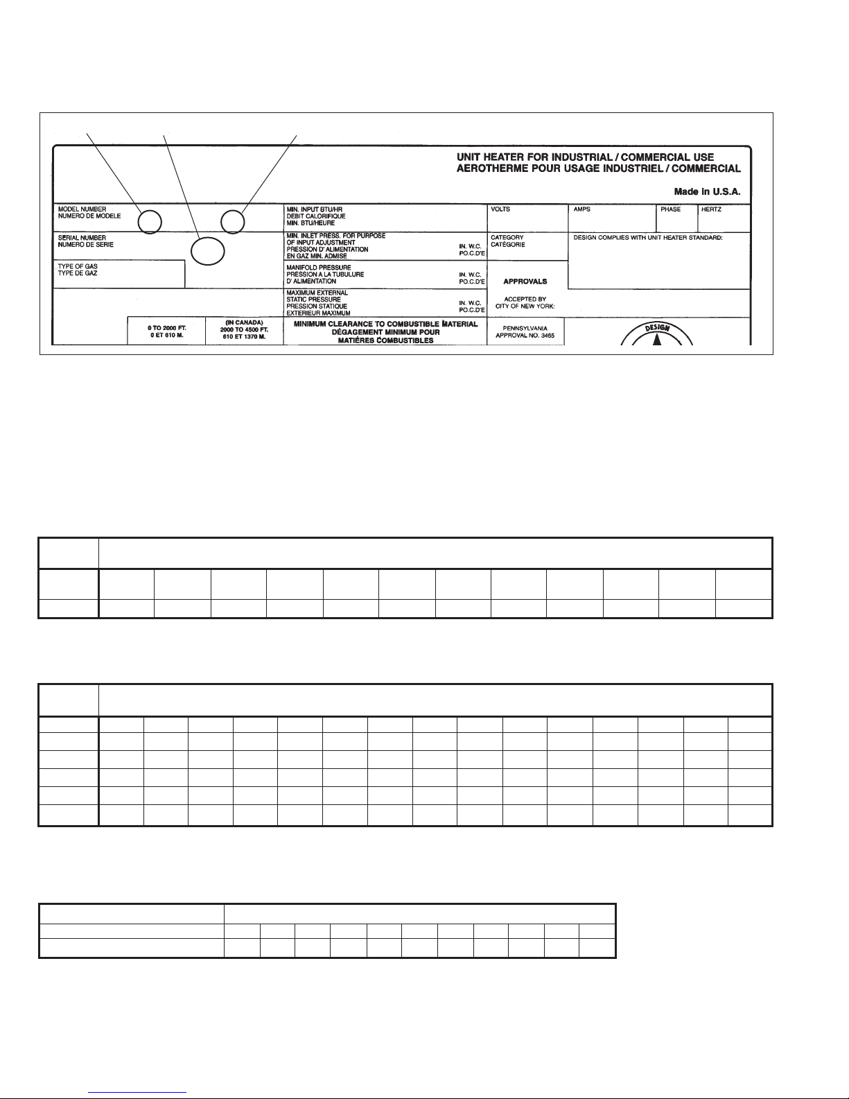
Figure 2.1, shown on the next page, is an example of a typical
serial plate. Markings pertinent to verifying correct application
of the conversion kit are identified and explained in detail. All
prerequisites must be satisfied before the unit is deemed
convertible.
1. The first two or three characters in the model number box
are letters. These letters identify the style of the heater. If
any of the following model prefixes appear in this box, the
unit is potentially convertible: PD/BD, PDP/BDP, PV/BV,
DJE, IJE, DFG, IFG, NFG, DFP, IFP, DFS, IFS.
2. Next, the number 11, 12, 13, 14, 30, 31, 32, or 33 must be
the control code or digits 11 and 12 of the model number
are N1 or S1. This is item (2) in Figure 2.1. Any other
number code disqualifies the unit for conversion.
3. Item (3) in Figure 2.1 in the serial number box designates
the date the unit was built. In Figure 2.1, the numbers
3601 are shown. This number is interpreted as the thirty
sixth week of 2001. Prior to January 1995, the digits
preceding the year represent month of manufacture. After
January 1995, the (2) digits proceeding the year represent
the week of manufacture. Any serial number dated 4/91 or
after is acceptable for conversion.
THIS MANUAL IS THE PROPERTY OF THE OWNER. PLEASE BE SURE TO LEAVE IT WITH THE OWNER WHEN YOU LEAVE THE JOB.
NATURAL TO PROPANE CONVERSION KIT SELECTION GUIDE
Figure 2.1
Typical Serial Plate
j lk
Modine Manufacturing Company
1221 Magnolia Ave., Buena Vista, VA 24416; Phone: 540-261-2166
PD 250AA0111 115 5.7 1 60
30011013601-0978 6.0 I ANS Z83.8 - 96
Natural 3.5 CGA-2.6-M96
0.0 MEA 293-96-E
Selection of the Proper Kit
Referring to the model number box on the serial plate in Figure
2.1 (above), the prefix letters and succeeding numbers which are
needed for kit selection are PD250.
The letters identify the model, and the numbers indicate the size
of the unit. Referring to Tables 2.1, 2.2, or 2.3 locate the model
type column (i.e. PD, BD, etc.). Working with Table 2.1 and the
row labeled PD/BD, move right searching for the proper model
size. Read the kit number suffix directly below the model size
for a PD250. Add this suffix (-9) to the base part number for the
propane conversion kit shown in the heading of Table 2.1. The
correct kit for a PD250 with Control Code 11, is 3H034670-9.
Table 2.1
Natural Gas to Propane Gas Conversion Kit Selection Guide
Base Kit Number – 3H034670…(Choose correct suffix -1, -2, -3, etc…)
Model
Type
PD/BD,
PDP/BDP 30 50 75 100 125 150 175 200 250 300 350 400
Suffix -1 -2 -3 -4 -5 -6 -7 -8 -9 -10 -11 -12
Model Size
Table 2.2
Natural Gas to Propane Gas Conversion Kit Selection Guide (For units manufactured after April 1, 1991)
Base Kit Number – 3H33749…(Choose correct suffix -1, -2, -3 etc., per instructions, before ordering propane conversion kits.)
Model
Type
PAE/BAE 30 50 75 100 125 145 – 175 200 225 – 250 300 350 400
Suffix -1 -2 *-14 -4 -5 -6 – -7 -8 -9 – -10 -11 -12 -13
PV/BV 30 50 75 100 125 145 – 175 200 – – 250 300 350 400
Suffix -1 -2 -14 -4 -5 -6 – -7 -8 – – -10 -11 -12 -13
DJE/DHE – – 75 100 125 – 150 – 200 225 – 250 300 350 400
Suffix – – -14 -15 -16 – -6 – -8 -17 – -10 -11 -18 -13
Model Size
* For units manufactured after September, 1993. For units manufactured prior to this date, consult the factory.
Table 2.3
Natural Gas to Propane Gas Conversion Kit Selection Guide
Base Kit Number – 3H036483…(Choose correct suffix -1, -2, -3 etc...)
Model Type Model Size
DFG/IFG/NFG, DFP/IFP, DFS/IFS 75 100 125 150 175 200 225 250 300 350 400
Suffix -1 -2 -3 -4 -5 -6 -7 -8 -9 -10 -11
2
75-511.13

INSTALLATION
Installation of Kit
Conversion of any unit is the responsibility of, and the
risk of the person making the conversion.
1. All field gas piping must be pressure/leak tested prior to
operation. Never use an open flame. Use a soap solution
or equivalent for testing.
2. Gas supply shall be shut-off and the electrical power
disconnected before proceeding with the conversion.
Failure to do so could result in re, explosion or electrical
shock.
General
1. Shut off gas supply to the unit. Disconnect the electrical
power to the unit.
2. For codes 11, 12, 13, 14 or if digit 11 of the model number
is S or T and digit 12 is 1, disconnect the pilot gas tube
and thermocouple lead at the combination gas control. For
codes 30, 31, 32, 33 or if digit 11 of the model number is
N or P and if digit 12 is 1, disconnect the pilot gas tube at
the combination gas control and the ignition cable(s) at the
ignition control.
3. Remove burner assembly.
For PD/BD, PDP/BDP, and PV/BV Models
Lower bottom pan to expose burner and manifold (see Figure
3.1).
For codes 11, 12, 13, or 14, disconnect pilot gas tube and
thermocouple lead at the controls. For codes 30, 31, 32, or 33,
disconnect the pilot gas tube at the combination gas control and
the ignition cable(s) at the ignition control.
Remove the two burner retaining pins holding the burner in place
(see Figure 3.2). The burner can then be easily lowered from
the unit. In replacing the burner, be certain that the slots at the
front of the burner are located properly on their shoulder rivets
and that the burner retaining pins are put back into their proper
locations.
After removing burner assembly, proceed with step #4, page 4.
WARNING
Figure 3.1
Hinged Bottom for Burner Service
Figure 3.2
Manifold Adjustment
MIXER
TUBES
BURNER
RETAINING PIN
For Indoor Duct Furnace Models
On DHE/IHE models, lower the controls enclosure cover and
disconnect the pilot gas supply line and thermocouple at the gas
valve. On models DJE/IJE, DFG/IFG/NFG, DFP/IFP, DBG/IBG,
DCG/ICG, DBP/IBP, and DCP/ICP models, the gas controls are
exposed. On models DFS/IFS, remove lower assess door to
expose gas controls and burner.
The burner may be removed from either side of the duct furnace.
To remove the burner, remove all of the sheet metal screws
holding the side burner access panel in place. (Note: with the
side access panel screws removed, the access panel is free to
move, be careful not to drop the panel.)
Figure 3.3
75-511.13
BURNER SIDE
ACCESS PANEL
BURNER
ALIGNMENT PINS
PILOT
TUBE
THERMOCOUPLE
GAS
VALV E
LEAD
3
 Loading...