

Modine Manufacturing DFP, DFP75, DFP100, DFP125, DFP150 Service Manual
...
5-564
C
US
5H080637A
December, 2008
INSTALLATION AND SERVICE MANUAL
gas-fired indoor power vented duct furnaces
model DFP
All models approved for use in California by the CEC
FOR YOUR SAFETY
IF YOU SMELL GAS:
1. Open windows.
2. Don’t touch electrical switches.
3. Extinguish any open flame.
4. Immediately call your gas supplier.
WARNING
Improper installation, adjustment, alteration,
service or maintenance can cause property
damage, injury or death, and could cause
exposure to substances which have been
determined by various state agencies to cause
cancer, birth defects or other reproductive
harm. Read the installation, operating and
maintenance instructions thoroughly before
installing or servicing this equipment.
CAUTION
To prevent premature heat exchanger failure do
not locate ANY gas-fired units in areas where
chlorinated, halogenated, or acid vapors are
present in the atmosphere.
FOR YOUR SAFETY
The use and storage of gasoline or other
flammable vapors and liquids in open containers
in the vicinity of this appliance is hazardous.
IMPORTANT
The use of this manual is specifically intended
for a qualified installation and service agency.
A qualified installation and service agency must
perform all installation and service of these
appliances.
Inspection on Arrival
1. Inspect unit upon arrival. In case of damage, report it
immediately to transportation company and your local factory
sales representative.
2.
Check rating plate on unit to verify that power supply meets
available electric power at the point of installation.
3. Inspect unit upon arrival for conformance with description of
product ordered (including specifications where applicable).
PLEASE BE SURE TO LEAVE IT WITH THE OWNER WHEN YOU LEAVE THE JOB.
THIS MANUAL IS THE PROPERTY OF THE OWNER.
5-564
SPECIAL PRECAUTIONS / TABLE OF CONTENTS
SPECIAL PRECAUTIONS
THE INSTALLATION AND MAINTENANCE INSTRUCTIONS
IN THIS MANUAL MUST BE FOLLOWED TO PROVIDE SAFE,
EFFICIENT AND TROUBLE-FREE OPERATION. IN ADDITION,
PARTICULAR CARE MUST BE EXERCISED REGARDING
THE SPECIAL PRECAUTIONS LISTED BELOW. FAILURE
TO PROPERLY ADDRESS THESE CRITICAL AREAS COULD
RESULT IN PROPERTY DAMAGE OR LOSS, PERSONAL
INJURY, OR DEATH. THESE INSTRUCTIONS ARE SUBJECT
TO ANY MORE RESTRICTIVE LOCAL OR NATIONAL CODES.
HAZARD INTENSITY LEVELS
1. DANGER: Indicates an imminently hazardous situation which,
if not avoided, WILL result in death or serious injury.
2. WARNING: Indicates a potentially hazardous situation which, if
not avoided, COULD result in death or serious injury.
3. CAUTION: Indicates a potentially hazardous situation which,
if not avoided, MAY result in minor or moderate injury.
4. IMPORTANT: Indicates a situation which, if not avoided,
MAY result in a potential safety concern.
DANGER
Appliances must not be installed where they may be
exposed to a potentially explosive or flammable atmosphere.
WARNING
1. Gas fired heating equipment must be vented - do not operate
unvented.
2. A built-in power exhauster is provided - additional external
power exhausters are not required or permitted.
3. If you are replacing an existing heater, it may be necessary to
resize the venting systems. Improperly sized venting systems
can result in vent gas leakage or the formation of condensate.
Refer to the National Fuel Gas Code ANSI Z223.1 or CSA
B149.1 latest edition. Failure to follow these instructions can
result in injury or death.
4. Under no circumstances should two sections of double wall
vent pipe be joined together within one horizontal vent system
due to the inability to verify complete seal of inner pipes.
5. All field gas piping must be pressure/leak tested prior to
operation. Never use an open flame. Use a soap solution or
equivalent for testing.
6. Gas pressure to appliance controls must never exceed 14"
W.C. (1/2 psi).
7. Disconnect power supply before making wiring connections
to prevent electrical shock and equipment damage.
8. All appliances must be wired strictly in accordance with
wiring diagram furnished with the appliance. Any wiring
different from the wiring diagram could result in a hazard
to persons and property.
9. To reduce the opportunity for condensation, the minimum
sea level input to the appliance, as indicated on the serial
plate, must not be less than 5% below the rated input, or
5% below the minimum rated input of duel rated units.
10. Ensure that the supply voltage to the appliance, as
indicated on the serial plate, is not 5% greater than the
rated voltage.
11. Any original factory wiring that requires replacement must
be replaced with wiring material having a temperature
rating of at least 105°C.
12.
When servicing or repairing this equipment, use only factory-
approved service replacement parts. A complete replacement
parts list may be obtained by contacting Modine Manufacturing
Company. Refer to the rating plate on the appliance for
complete appliance model number, serial number, and
company address. Any substitution of parts or controls not
approved by the factory will be at the owners risk.
2
2
5-564
CAUTION
1. Purging of air from gas lines should be performed as
described in ANSI Z223.1 - latest edition “National Fuel Gas
Code”, or in Canada in CAN/CGA-B149 codes.
2. Do not attempt to reuse any mechanical or electrical
controllers which have been wet. Replace defective controller.
3. Ensure that the supply voltage to the application, as indicated
on the serial plate, is not 5% less than the rated voltage.
IMPORTANT
1. To prevent premature heat exchanger failure, do not locate
ANY gas-fired appliances in areas where corrosive vapors
(i.e. chlorinated, halogenated or acid) are present in the
atmosphere.
2. To prevent premature heat exchanger failure, the input to
the appliance, as indicated on the serial plate, must not
exceed the rated input by more than 5%.
3. To prevent premature heat exchanger failure, observe heat
exchanger tubes by looking at the heat exchanger through
field installed access openings in connecting ductwork. If
the bottom of the tubes become red while blower and duct
furnace are in operation, additional baffles must be inserted
between blower and duct furnace to assure uniform air flow
across the heat exchanger.
4. To prevent premature heat exchanger failure, with all control
systems, a blower starting mechanism must be provided so
that the blower is running or energized within 45 seconds of
the gas control operation.
5. Start-up and adjustment procedures should be performed
by a qualified service agency.
6. To check most of the Possible Remedies in the troubleshooting
guide listed in Table 20.1, refer to the applicable sections
of the manual.
Table of Contents
Inspection on Arrival ................................................................. 1
Special Precautions .................................................................. 2
SI (Metric) Conversion Factors ................................................. 3
Unit Location ............................................................................. 3
Location Recommendations .............................................. 3
Combustible Material and Service Clearances ................. 3
Combustion Air Requirements ........................................... 3
Unit Suspension ....................................................................... 4
Installation ................................................................................ 4
Direction of Airflow ............................................................. 4
Duct Installation and Airflow Distribution ........................ 4-5
Venting ........................................................................... 5-6
Gas Connections ............................................................... 7
Electrical Connections ....................................................... 8
Start-Up Procedure ................................................................... 8
Pilot Burner and Main Burner Adjustment ......................... 9
Air Shutter Adjustment ..................................................... 10
Control Operating Sequence ...................................... 11-13
Variable Air Movement Applications ................................ 13
Gas Control Options ................................................... 13-14
Dimensional Data ................................................................... 15
Performance ........................................................................... 16
Air Temperature and External Static Pressure Limits ...... 16
Pressure Drop Curves ............................................................ 17
Maintenance ........................................................................... 18
Manifold Assembly Removal ........................................... 18
Burner and Pilot Assembly Removal .......................... 18-19
Service & Troubleshooting .................................................20-21
Replacement Parts Ordering .................................................. 22
Model Identification ................................................................. 22
Commercial Warranty ................................................ Back Page
SI (METRIC) CONVERSION FACTORS / UNIT LOCATION
SI (METRIC) CONVERSION FACTORS
Table 3.1
To Convert Multiply By To Obtain
"W.C. 0.24 kPa
psig 6.893 kPa
°F (°F-32) x 0.555 °C
inches 25.4 mm
feet 0.305 meters
CFM 0.028 m3/min
To Convert Multiply By To Obtain
CFH 1.699 m3/min
Btu/ft3 0.0374 mJ/m
pound 0.453 kg
Btu/hr 0.000293 kW/hr
gallons 3.785 liters
psig 27.7 "W.C.
3
UNIT LOCATION
DANGER
Appliances must not be installed where they may be exposed
to a potentially explosive or flammable atmosphere.
IMPORTANT
To prevent premature heat exchanger failure, do not locate
ANY gas-fired appliances in areas where corrosive vapors (i.e.
chlorinated, halogenated or acid) are present in the atmosphere.
Location Recommendations
1. When locating the furnace, consider general space and
heating requirements, availability of gas and electrical
supply, and proximity to vent locations.
2. Unit must be installed on the positive pressure side of the
circulating blower.
3. Be sure the structural support at the unit location site is
adequate to support the weight of the unit. For proper
operation the unit must be installed in a level horizontal
position.
4. Do not install units in locations where the flue products
can be drawn into the adjacent building openings such as
windows, fresh air intakes, etc.
5. Be sure that the minimum clearances to combustible
materials and recommended service clearances are
maintained. Units are designed for installation on noncombustible surfaces with the minimum clearances shown
in Figure 3.1 and Tables 3.2 and 3.3.
6. Units installed downstream of refrigeration systems, or
exposed to inlet air temperatures of 40°F or less, may
experience condensation, therefore, provisions should
be made for disposal of condensate. Means have been
provided in the bottom pan of the unit to accommodate a
condensate drain line connection flange.
7. When locating units, it is important to consider that the
exhaust vent piping must be connected to the outside
atmosphere.
8. In garages or other sections of aircraft hangars such as
offices and shops which communicate with areas used for
servicing or storage, keep the bottom of the unit at least 7”
above the floor. In public garages, the unit must be installed
in accordance with the Standard for Parking Structures
NFPA #88A and the Standard for Repair Garages NFPA
#88B. In Canada, installation of unit heaters in airplane
hangars must be in accordance with the requirements of
the enforcing authority, and in public garages in accordance
with the current CAN/CGA-B149 codes.
9. Do not install units in locations where gas ignition system is
exposed to water spray, rain, or dripping water.
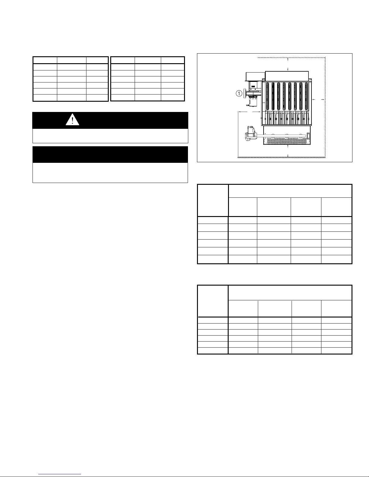
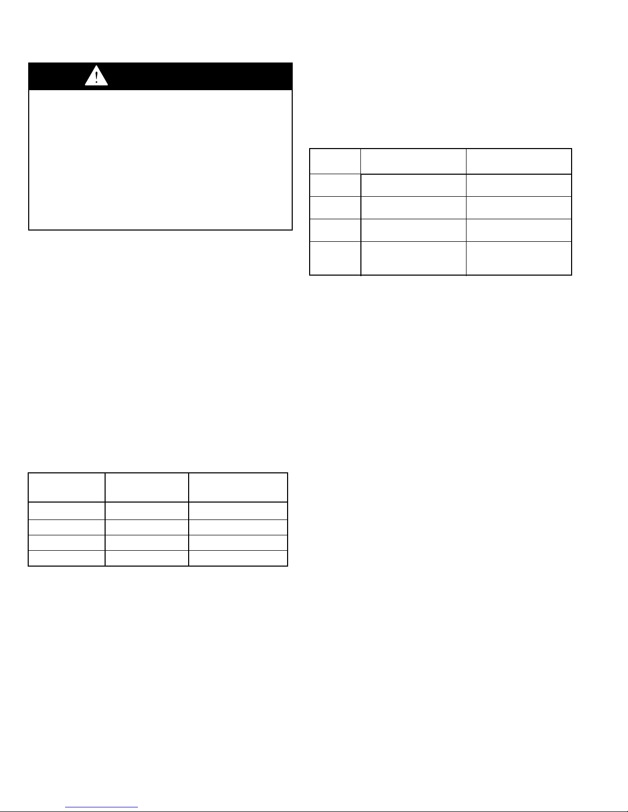
Figure 3.1 - Combustible Material and Service
Clearances
C
Access
Slide
B
A
D"
➀ A 3'' minimum clearance to combustible material is required from the vent collar.
Table 3.2 - Combustible Material Clearances
Clearance to
Combustible Materials
Model Access
Size Side Side (C) (D)
(A) (B)
75 12" 1" 3" 2"
100/125 12" 1" 3" 2"
150/175 12" 1" 3" 2"
200/225 12" 2" 3" 2"
250/300 12" 2" 3" 2"
350/400 12" 2" 3" 2"
Non-Access
Top Bottom
Table 3.3 - Service Clearances
Recommended
Service
Clearance
Model Access Non-Access Top Bottom
Size Side Side (C) (D)
(A) (B)
75 18" 6" 10" 0"
100/125 20" 6" 10" 0"
150/175 25" 6" 10" 0"
200/225 27" 6" 10" 0"
250/300 30" 6" 10" 0"
350/400 41" 6" 10" 0"
Combustion Air Requirements
Units installed in tightly sealed buildings or confined spaces
must be provided with two permanent openings, one near
the top of the confined space and one near the bottom. Each
opening should have a free area of not less than one square
inch per 1,000 BTU per hour of the total input rating off all
units in the enclosure, freely communicating with interior areas
having, in turn adequate infiltration from the outside.
For further details on supplying combustion air to a confined
(tightly sealed) space or unconfined space, see the National
Fuel Gas Code ANSI Z223.1 of CAN/CGA B149.1 or .2
Installation Code, latest edition.
5-564
33
UNIT SUSPENSION / INSTALLATION
UNIT SUSPENSION
Be sure the means of suspension is adequate to support the
weight of the unit (see Dimensional Data for unit weights). For
proper operation, the unit must be installed in a level horizontal
position. Combustible material and service clearances as
specified in Figure 3.1 and Tables 3.2 and 3.3 must be strictly
maintained.
1. Four 1/2" - 13NC tapped holes in top of furnace are provided
to accept ceiling hangers. To assure that flames are directed
into the center of the heat exchanger tubes, the furnace must
be supported in a vertical position. Use a spirit level to ensure
that unit is suspended correctly.
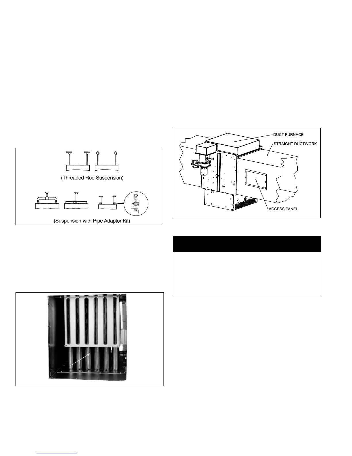
2. NOTE: A pipe hanger adapter kit, shown in Figure 4.1, is
available as an accessory. One kit consists of two drilled
3/4" IPS pipe caps and two 1/2 - 13 x 1-3/4" capscrews to
facilitate threaded pipe suspension. Two kits are required for
mounting all duct furnace models.
Figure 4.1 - Suspension Methods
Duct Installation
1. The furnace is designed to accept straight ductwork. See
Figure 4.3. Provide an airtight seal between the ductwork
and the furnace. Seams with cracks in ductwork should be
caulked and/or taped and be of permanent type. All duct
connections MUST be airtight to prevent air leakage.
2. Provide removable access panels on both the upstream and
downstream sides of the ductwork; see Figure 4.3. These
openings should be large enough to view smoke or reflect
light inside the casing to indicate leaks in the heat exchanger
and to check for hot spots on heat exchangers due to poor air
distribution or lack of sufficient air (CFM)
Figure 4.3 - Duct Connections
C
INSTALLATION
Direction of Airflow
Select proper direction of airflow. The air baffle must face the
air inlet direction as shown in Figure 4.2. If it is necessary to
reverse the airflow direction, remove the four screws securing
the air distribution baffle, reverse the air distribution baffle to the
air inlet side and replace the screws. See Airflow Reversal Note.
Figure 4.2 - Air Distribution Baffle Location
Baffle location shown on entering air side of duct furnace.
AIR
DISTRIBUTION
BAFFLE
Airflow Distribution
IMPORTANT
To prevent premature heat exchanger failure, observe heat
exchanger tubes by looking at the heat exchanger through
field installed access openings in connecting ductwork. If
the bottom of the tubes become red while blower and duct
furnace are in operation, additional baffles must be inserted
between blower and duct furnace to assure uniform air flow
across the heat exchanger.
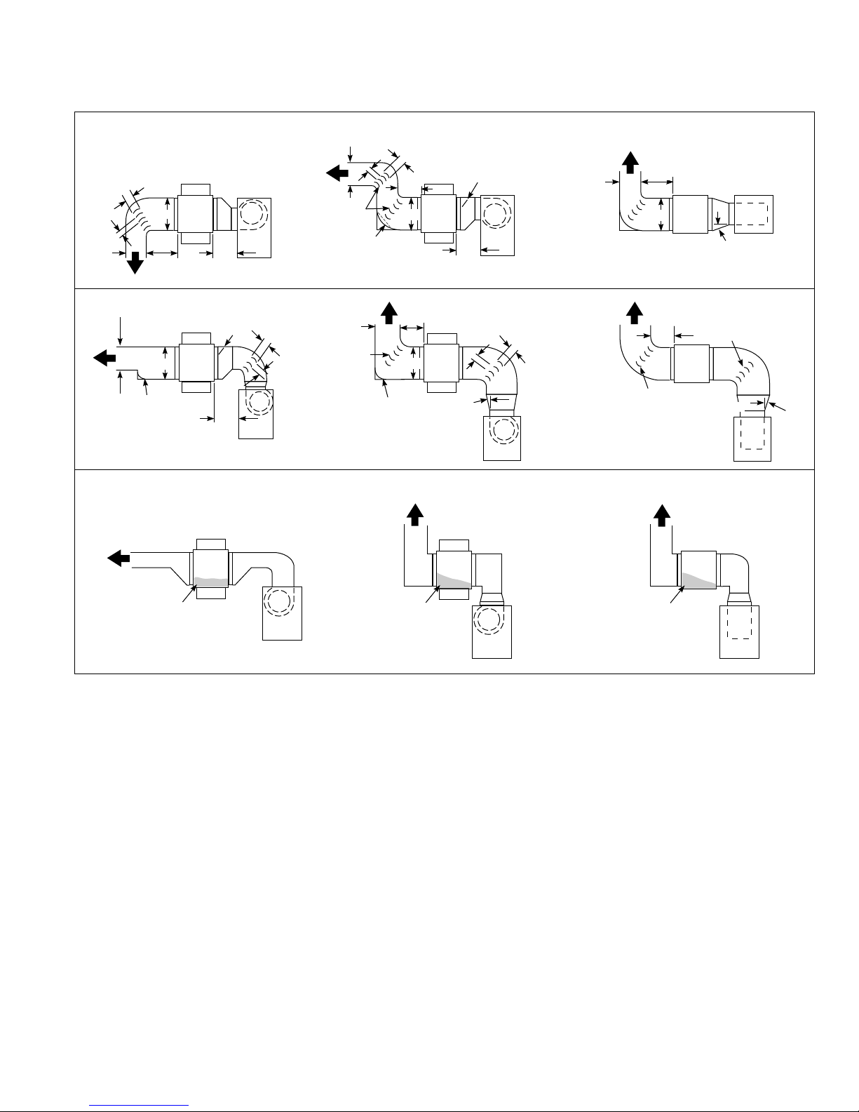
1. Provide uniform air distribution over the heat exchanger.
Use turning vanes where required (see Figure 5.1) to obtain
uniform air distribution. Avoid installing as in “G”, “H” & “J” of
Figure 5.1.
2. A bottom, horizontal discharge type blower should be
installed at least 12" from the furnace (See “A”, Figure 5.1).
3. A top, horizontal discharge type blower should be installed at
least 24" from the furnace (See “B”, Figure 5.1). Provide air
baffle at top of duct to deflect air down to the bottom of heat
exchanger.
Airflow Reversal Note: If factory installed discharge air options
(thermostat, freeze protection, etc.) were provided, these
options would have to be relocated to the discharge air side of
the duct furnace.
4
5-564
INSTALLATION
Figure 5.1 - Typical Duct & Airflow Installation
3" Max.
Turning
Vanes
3" Min.
B
B
A
12"
Min.
A
Baffle
SIDE VIEW
12"
Min.
SIDE VIEW
Air
Baffle
24"
Min.
G
POOR
3" Max.
RECOMMENCED INSTALLATIONS
RECOMMENDED INSTALLATIONS
3" Max.
B
Turning
Vanes
Baffle
12"
Min.
A
3" Min.
B
Air
Baffle
24"
Min.
SIDE VIEW
Turning
Vanes
3" Max.
15° Max.
Turning
Vanes
B
Baffle
12"
Min.
A
SIDE VIEW
INSTALLATIONS NOT RECOMMENDED
H
POOR
3" Min.
Turning
Van es
Dimensions “B” should never
be less than
CA
12"
Min.
B
A
15° Max.
TOP VIEW
FED
Turning
12"
Min.
Turning
Vanes
Van es
15° Max.
TOP VIEW
J
POOR
1
¼2 of “A”.
No Air
SIDE VIEW
No Air
SIDE VIEW
No Air
TOP VIEW
5-564
5
INSTALLATION
Venting
WARNING
1. Gas fired heating equipment must be vented - do not
operate unvented.
2. A built-in power exhauster is provided - additional external
power exhausters are not required or permitted.
3. If you are replacing an existing heater, it may be necessary
to resize the venting systems. Improperly sized venting
systems can result in vent gas leakage or the formation of
condensate. Refer to the National Fuel Gas Code ANSI
Z223.1 or CSA B149.1 latest edition. Failure to follow these
instructions can result in injury or death.
4. Under no circumstances should two sections of double wall
vent pipe be joined together within one horizontal vent system
due to the inability to verify complete seal of inner pipes.
NOTE: A vent is the vertical passageway used to convey
flue gases from the unit or the vent connector to the outside
atmosphere. A vent connector is the pipe which connects the
unit to a vent or chimney. Vent connectors serving Category
I appliances shall not be connected into any portion of
mechanical draft systems operating under positive pressure.
General Venting Instructions
1. Installation of venting must conform with local building codes,
or in the absence of local codes, with the National Fuel Gas
Code, ANSI Z223.1 (NFPA 54) - Latest Edition. In Canada,
installation must be in accordance with CAN/CGA-B149.1 for
natural gas units and CAN/CGA-B149.2 for propane units.
2. All vertically vented units are Category I. All horizontally vented
units are Category III. The installation must conform to the
requirements from Table 6.2 in addition to those listed below.
3. For units vented as Category I, refer to Table 6.1 for vent
sizing. Vent sizing for units vented as Category III are covered
in a later section on page 7. Do not use a vent pipe smaller
than the size of the outlet or vent transition of the appliance.
The pipe should be suitable corrosion resistant material.
Follow the National Fuel Gas Code for minimum thickness
and composition of vent material. The minimum thickness for
connectors varies depending on the pipe diameter.
Table 6.1 - Vertical Category I Vent Sizing Requirements
Vent Connector
Model Size
75-125
150-175 4" 5"
200 6" 6"
225-400
➀ Requires a 4" to 5" adapter for the larger vent pipe diameter.
4. For Category I vent systems limit length of horizontal runs to
75% of vertical height. Install with a minimum upward slope
from unit of 1/4 inch per foot and suspend securely from
overhead structure at points no greater than 3 feet apart.
For best venting, put vertical vent as close to the unit as
possible. A minimum of 12" straight pipe is recommended
from the power exhauster outlet before turns in the vent
system. Fasten individual lengths of vent together with at
least three corrosion-resistant sheet-metal screws.
5. It is recommended that vent pipes be fitted with a tee with a
drip leg and a clean out cap to prevent any moisture in the
vent pipe from entering the unit. The drip leg should be inspected
and cleaned out periodically during the heating season.
6. The National Fuel Gas Code requires a minimum clearance
of 6 inches from combustible materials for single wall vent
pipe. The minimum distance from combustible materials is
based on the combustible material surface not exceeding
160°F. Clearance from the vent pipe (or the top of the unit)
may be required to be greater than 6 inches if heat damage
other than fire (such as material distortion or discoloration)
could result.
Diameter
4" 4"
6” 6”
Minimum Vent Pipe
Diameter
➀
7. Avoid venting through unheated space. When venting does
pass through an unheated space, insulate runs greater than
5 feet to minimize condensation. Inspect for leakage prior to
insulating and use insulation that is noncombustible with a
rating of not less than 350°F. Install a tee fitting at the low
point of the vent system and provide a drip leg with a clean
out cap as shown in Figure 7.1.
Table 6.2 - ANSI Venting Requirements
Appliance Venting
Category Description Requirements
I Negative vent pressure Follow standard venting
Non-condensing requirements.
II Negative vent pressure Condensate must be
Condensing drained.
III Positive vent pressure Vent must be gastight.
Non-condensing
IV Positive vent pressure Vent must be liquid and
Condensing gastight. Condensate must
be drained.
8. When the vent passes through a combustible wall or floor,
a metal thimble 4 inches greater than the vent diameter is
necessary. If there is 6 feet or more of vent pipe in the
open space between the appliance and where the vent
pipe passes through the wall or floor, the thimble need only
be 2 inches greater than the diameter of the vent pipe. If a
thimble is not used, all combustible material must be cut
away to provide 6 inches of clearance. Any material used
to close the opening must be noncombustible.
9. Do NOT use dampers or other devices in the vent pipes.
10. Precautions must be taken to prevent degradation of
building materials by flue products.
11. For category I vent systems the outlet of the vent should
extend as shown in Figure 7.1 and Table 7.1 if the following
conditions are met:
• Vent diameter is less than 12 inches, vent is of double
wall construction and is a listed product, and the vent
does not terminate within 2' of a vertical wall or similar
obstruction.
• For vents that have a diameter of 12 inches or larger,
constructed of single wall, or terminate within 2' of a
vertical wall or similar obstruction, the vent pipe shall
extend at least 2' higher than any portion of a building
within a horizontal distance of 10' (refer to Figure 7.1).
12. Use a listed vent terminal to reduce downdrafts and
moisture in vent.
13. For instructions on common venting refer to the National
Fuel Gas Code.
14. The vent must terminate no less than 5' above the vent
connector for Category I vent systems.
15. A unit located within an unoccupied attic or concealed space
shall not be vented with single wall vent pipe.
16. Single wall vent pipe must not pass through any attic, inside
wall, concealed space, or floor.
17. Do NOT vent this appliance into a masonry chimney.
18. When condensation may be a problem, the venting system
shall not terminate over public walkways or over an area
where condensation or vapor could create a nuisance or
hazard or could be detrimental to the operation of regulator
relief openings or other equipment.
19. In cold ambient conditions, such as Canada, the following
items are recommended for proper operation and
equipment life:
• The vent pipe must not pass through an unheated space
or interior part of an open chimney unless the vent pipe is
insulated.
• Where the vent pipe may be exposed to extreme cold, or
come into contact with snow or ice, the entire vent must
be insulated or double wall (includes outdoors). It is
preferred that the double wall vent is one continuous
piece but a joint is allowed outside the building.
• The heater system shall be checked at least once a year
by a qualified service technician.
6
5-564
TEE WITH DRIP LEG
AND CLEANOUT CAP
AT LOW POINT OF
VENT SYSTEM
POWER EXHAUSTER OUTLET
PITCH VENT PIPE DOWNWARD
FROM UNIT 1/4" PER FOOT
12"
Min.
GARY STEEL
MODEL 1092 TERMINAL
INSTALLATION
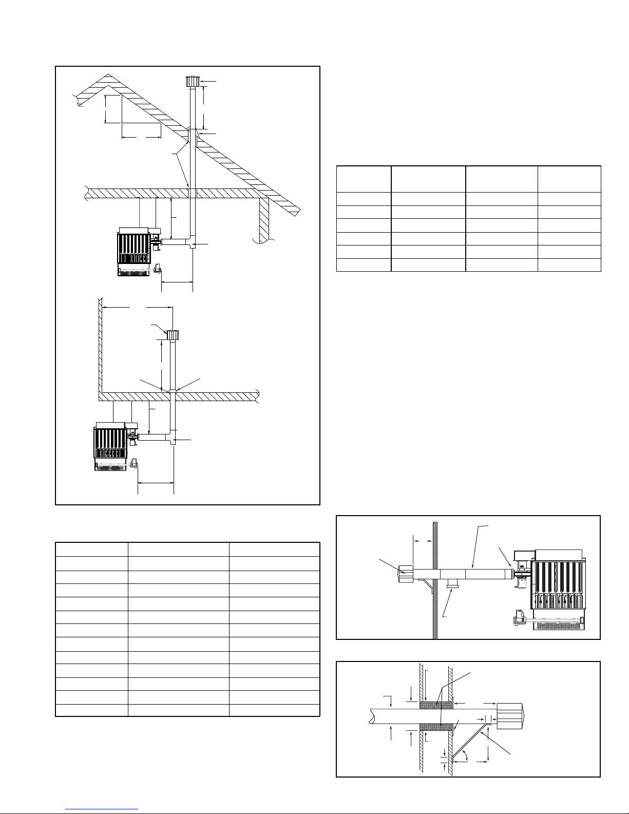
Figure 7.1 - Vertical Category I Vent System
LISTED TERMINAL
EXHAUST
12" MIN
4" MIN
* SIZE ACCORNING
TO EXPECTED
SNOW DEPTH.
"H" MIN*
ROOF FLASHING
TEE WITH DRIP LEG
AND CLEANOUT CAP
(SLOPE 1/4" PER
FOOT DOWNWARD
TOWARD DRIP LEG)
ROOF FLASHING
TEE WITH DRIP LEG
AND CLEANOUT CAP
(SLOPE 1/4" PER
FOOT DOWNWARD
TOWARD DRIP LEG)
X
ROOF PITCH IS:
X / 12
BACK VIEW
TO WALL OR ADJOINING BUILDING
12
USE LISTED THIMBLE
THROUGH ROOF AND
CEILING
2' MIN
TERMINAL
USE THIMBLE
THROUGH
CELLING
2' MIN*
4" MIN
EXHAUST
12" MIN
RECOMMENDED
RECOMMENDED
Table 7.1 - Minimum Height from Roof to Lowest
Discharge Opening
Rise X (in) Roof Pitch Min Height H (ft) ➀
0-6 Flat to 6/12 1.00
6-7 6/12 to 7/12 1.25
7-8 7/12 to 8/12 1.50
8-9 8/12 to 9/12 2.00
9-10 9/12 to 10/12 2.50
10-11 10/12 to 11/12 3.25
11-12 11/12 to 12/12 4.00
12-14 12/12 to 14/12 5.00
14-16 14/12 to 16/12 6.00
16-18 16/12 to 18/12 7.00
18-20 18/12 to 20/12 7.50
20-21 20/12 to 21/12 8.00
➀ Size according to expected snow depth.
Additional Requirements for Horizontally Vented
Category III Units
1. Seal the joints with a metallic tape or silastic suitable for
temperatures up to 350°F. (3M tapes 433 or 363 are
acceptable.) Wrap tape two full turns around the vent pipe.
2. Refer to Table 7.2 for total minimum and maximum vent
lengths making the vent system as straight as possible.
The equivalent length of a 90° elbow is 5 feet for 4" diameter
and 7 feet for 6" diameter.
Table 7.2 - Horizontal Category III Vent Sizing
Requirements
Vent Connector
Model Size
75
100-175
200
225
250-300
350-400
➀ Unit can be vented with 5" diameter pipe if a 6" to 5" reducer is used.
Otherwise, use 6" pipe.
Diameter
4" 4" 48'
4" 4" 55'
6"
6"
6" 6" 63'
6" 6" 70'
3. The vent terminal must be a Gary Steel 1092.
4. The vent must extend a minimum of 12" beyond the exterior
wall surface as shown in Figure 7.2. The vent must be
supported as shown in Figure 7.3. Precautions must be taken
to prevent degradation of building materials by flue products.
5. The vent system shall terminate at least 3 feet above any
forced air inlet (except direct vent units) located within 10 feet,
and at least 4 feet below, 4 feet horizontally from, or 1 foot
above any door, window, or gravity air inlet into any building.
The bottom of the vent terminal shall be located above the
snow line or at least 1 foot above grade; whichever is greater.
When located adjacent to public walkways the vent system
shall terminate not less than 7 feet above grade.
6. The venting system must be exclusive to a single unit, and
no other unit is allowed to be vented into it.
7. Horizontally vented units must use single wall vent pipe
although one continuous section of double wall vent pipe
may be used with the vent system. Under no circumstances
should two sections of double wall vent pipe be joined
together within one vent system due to the inability to verify
complete seal of inner pipes.
Minimum Vent
Pipe Diameter
5" ➀ 70'
6" 70'
Maxium Vent
Length
Figure 7.2 - Horizontal Venting
Figure 7.3 - Venting Through Combustible Walls
METAL FACE
PLATE
45
1"
FIBER GLASS
INSULATION
MIN. 2"
12" min
1"
9"
9"
VENT TERMINATION
SUPPORT BRACKET
(where required)
(Make from 1" x 1" steel angle)
VENT PIPE
DIAMETER
2" MIN.
2" MIN.
METAL
SLEEVE
METAL
SLEEVE
5-564
7
INSTALLATION
Gas Connections
WARNING
1. All field gas piping must be pressure/leak tested prior to
operation. Never use an open flame. Use a soap solution or
equivalent for testing.
2. Gas pressure to appliance controls must never exceed 14"
W.C. (1/2 psi).
3. To reduce the opportunity for condensation, the minimum sea
level input to the appliance, as indicated on the serial plate,
must not be less than 5% below the rated input, or 5% below
the minimum rated input of duel rated units.
CAUTION
Purging of air from gas lines should be performed as
described in ANSI Z223.1 - latest edition “National Fuel Gas
Code”, or in Canada in CAN/CGA-B149 codes.
IMPORTANT
To prevent premature heat exchanger failure, the input to the
appliance, as indicated on the serial plate, must not exceed
the rated input by more than 5%.
1. Installation of piping must conform with local building codes,
or in the absence of local codes, with the National Fuel Gas
Code, ANSI Z223.1 (NFPA 54) - Latest Edition. In Canada,
installation must be in accordance with CAN/CGA-B149.1 for
natural gas units and CAN/CGA-B149.2 for propane units.
2. Piping to units should conform with local and national
requirements for type and volume of gas handled, and
pressure drop allowed in the line. Refer to Table 10.1 to
determine the cubic feet per hour (cfh) for the type of gas
and size of unit to be installed. Using this cfh value and the
length of pipe necessary, determine the pipe diameter from
Table 8.1. Where several units are served by the same main,
the total capacity, cfh and length of main must be considered.
Avoid pipe sizes smaller than 1/2". Table 8.1 allows for a 0.3"
W.C. pressure drop in the supply pressure from the building
main to the unit. The inlet pressure to the unit must be 6-7"
W.C. for natural gas and 11-14" W.C. for propane gas. When
sizing the inlet gas pipe diameter, make sure that the unit
supply pressure can be met after the 0.3" W.C. has been
subtracted. If the 0.3" W.C. pressure drop is too high, refer to
the Gas Engineer’s Handbook for other gas pipe capacities.
3. The gas piping to the unit can enter the unit from the side of
the unit or from below. Install a ground joint union with brass
seat and a manual shut-off valve external of the unit casing,
and adjacent to the unit for emergency shut-off and easy
servicing of controls, including a 1/8" NPT plugged tapping
accessible for test gauge connection (See Figure 8.1).
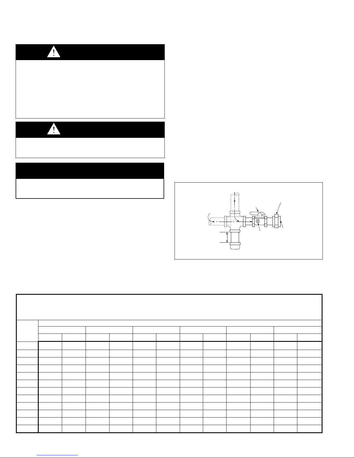
4. Provide a sediment trap before each unit in the line where low
spots cannot be avoided. (See Figure 8.1).
5. When Pressure/Leak testing, pressures above 14" W.C. (1/2
psi), close the field installed shut-off valve, disconnect the
appliance and its combination gas control from the gas supply
line, and plug the supply line before testing. When testing
pressures 14" W.C. (1/2 psi) or below, close the manual shutoff valve on the appliance before testing.
Figure 8.1 - Recommended Sediment Trap/Manual
Shut-off Valve Installation - Side or Bottom Gas
Connection
GAS
SUPPLY LINE
MANUAL GAS
TRAP
SHUT-OFF VALVE
PLUGGED
1/8" NPT TEST
GAGE CONNECTION
GAS
SUPPLY LINE
3"
MIN.
SEDIMENT
➀ Manual shut-off valve is in the “OFF” position when handle is perpendicular to
pipe.
➀
GROUND
JOINT
UNION
W/ BRASS
SEAT
TO
CONTROLS
Table 8.1 - Gas Pipe Capacities
Gas Pipe Capacities (Up to 14” W.C. Gas Pressure through Schedule 40 Pipe)
Length Pipe Diameter
Of Pipe 1/2" 3/4" 1" 1-1/4" 1-1/2" 2"
(feet) Natural Propane Natural Propane Natural Propane Natural Propane Natural Propane Natural Propane
10 132 83 278 175 520 328 1050 662 1600 1008 3050 1922
20 92 58 190 120 350 221 730 460 1100 693 2100 1323
30 73 46 152 96 285 180 590 372 890 561 1650 1040
40 63 40 130 82 245 154 500 315 760 479 1450 914
50 56 35 115 72 215 135 440 277 670 422 1270 800
60 50 32 105 66 195 123 400 252 610 384 1150 725
70 46 29 96 60 180 113 370 233 560 353 1050 662
80 43 27 90 57 170 107 350 221 530 334 990 624
90 40 25 84 53 160 101 320 202 490 309 930 586
100 38 24 79 50 150 95 305 192 460 290 870 548
125 34 21 72 45 130 82 275 173 410 258 780 491
150 31 20 64 40 120 76 250 158 380 239 710 447
8
Cubic Feet per Hour with Pressure Drop of 0.3” W.C.
Natural Gas - Specific Gravity - 0.60
Propane Gas - Specific Gravity - 1.50
5-564
 Loading...