

Modine Manufacturing HER250, HER150, HER30, HER50, POR185 Installation Instructions Manual
...
For:
Gas Models PDP150 - PDP/BDP400
Electric Models HER30 - 250
Oil Models POR100 - POR185
75-506.10
5H0703190000
April, 2017
INSTALLATION INSTRUCTIONS
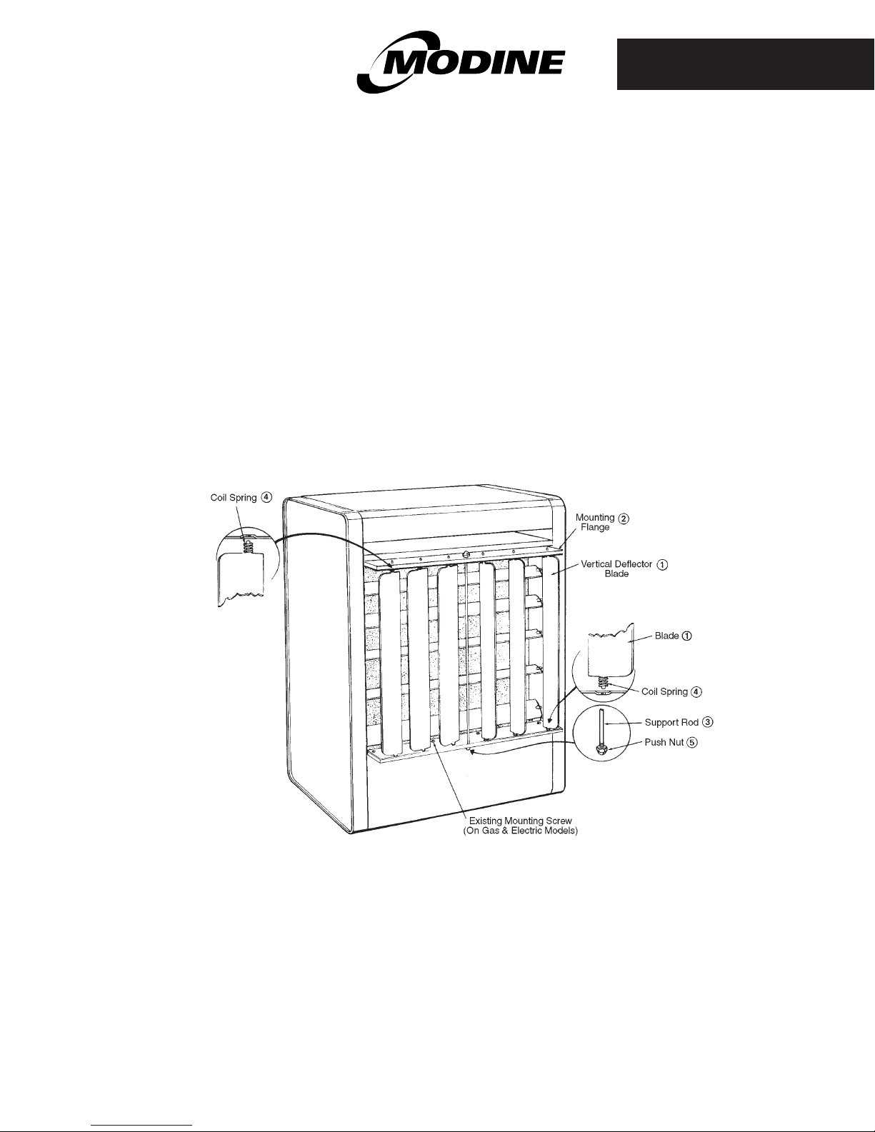
vertical air deflector blades
gas, electric and oil-fired unit heaters
1. Remove existing screws at the top and bottom of the air
discharge opening. (For oil-fired models, screws are
furnished in kit.)
2. Place the mounting flanges (item #2) so that the
indentations for the punched holes face each other, and
attach with the screws removed in step 1.
3. Insert the support rod (item #3) through the holes provided
in the mounting flanges. Secure this support rod with the
acorn push nuts (item #5) provided.
*NOTE: DO NOT OPERATE UNIT WITH DEFLECTOR BLADES IN A CLOSED POSITION.
As Modine Manufacturing Company has a continuous products improvement program, it reserves the right to change design and
specifications without notice.
4. Assemble the coil spring (item #4) provided to the straight
end of each deflector blade (item #1) and insert the ends of
the blades with the coil springs into holes in mounting
flanges. Push on the deflector blade until the beveded end
slips into the holes of the opposite mounting flange.
5. Adjust deflector blades to obtain desired direction of heat
throw.
page 1 of 2

1. Remove existing screws at the top and bottom of the right
hand air discharge opening.
2. Place the mounting flanges (item #2) so that the
indentations of the punched holes face each other, and
attach with the screws removed in step 1.
3. Insert the support rods (item #3) through the holes provided
in the mounting flanges. Secure these support rods with the
acorn push nuts (item #5) provided.
4. Assemble the coil springs (item #4) provided to the straight
end of each deflector blade (item #1) and insert the ends of
the blades with the coil springs into holes in the mounting
flanges. Push down on deflector blade until the beveled end
slips into the holes of the opposite mounting flange.
5. Repeat the same procedure for the left hand air discharge
opening.
6. Adjust deflector blades to obtain desired direction of heat
throw.
Unit Deflector Mounting Support Coil Push Metal
Model Item Kit Part Blade Flange Rod Spring Nut Screw
No. Code Number ➀ ➁ ➂ ➃ ➄ ➅
HER30 - HER50 32493 3H0261960043 6 2 1 6 2 -
HER50 - HER150 32488 3H0261960002 6 2 1 6 2 -
HER200 & 250 32489 3H0261960004 6 2 1 6 2 -
PDP/BDP150 78550 3H0261960005 6 2 1 6 2 -
PD/PDP/PDE/BDP175 78553 3H0261960006 6 2 1 6 2 -
PDP/BDP200 & 250 78556 3H0261960007 8 2 3 8 6 -
PD/PDP/PDE/BDP300 78559 3H0261960008 8 2 3 8 6 -
PDP/BDP350 78562 3H0261960010 10 4 4 10 8 -
PDP/BDP400 78565 3H0261960011 10 4 4 10 8 -
Part and Quantity
POR100 - 145 16412 3H0261960013 6 2 2 6 4 8
POR185 16415 3H0261960014 8 2 2 8 4 8
Modine Manufacturing Company • 1500 DeKoven Avenue • Racine, Wisconsin 53403-2552
Tel: 1.800.828.4328 (HEAT) • Fax: 262.636.1665 • www.modine.com
© 2017 Modine Manufacturing Company
page 2 of 2
 Loading...