

Modine Manufacturing HD 30, HD 45, HD 60, HD 75, HD 100 Product & Performance Data
...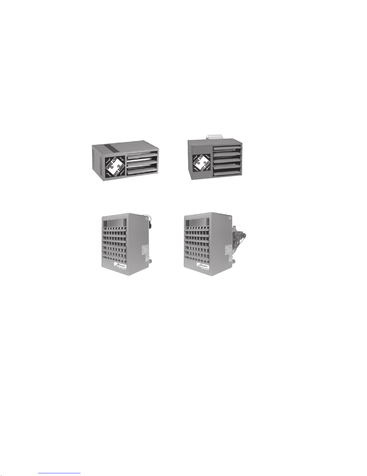
Gas-Fired Power Vented Unit Heaters
Propeller & Blower Models
MODEL HD MODEL HDB
6-189.5
July, 2009
MODEL PDP
MODEL BDP
6-189.5
TABLE OF CONTENTS
Modine’s power vented unit heaters are designed for the heating
requirements of commercial and industrial buildings with select
models available for residential garage heating as well.
For locations where negative pressure may be an issue or
energy savings over older gravity vented units may be desired,
Modine power vented gas fired unit heaters are your solution.
Table of Contents Page
Design Features - All Models...............................................................................3
Design Features - Model HD/HDB...........................................................................4
Design Features - Model PDP/BDP..........................................................................5
General Performance Data - Propeller Models HD/PDP..........................................................6
General Performance Data - Blower Models HDB/BDP ..........................................................7
Blower Performance Data - Blower Model HDB ................................................................8
Blower Performance Data - Blower Model BDP .............................................................9-11
Gas Control Data - All Models .............................................................................12
Field Installed Accessories................................................................................13
Downturn Hood Performance Data - Propeller Models HD/PDP ...................................................14
Velocity Generating Nozzle Performance Data - Blower Model BDP ...............................................15
Unit Selection.......................................................................................16-17
Dimensional Data - Models HD/HDB........................................................................18
Dimensional Data - Model PDP ............................................................................19
Dimensional Data - Model BDP ............................................................................20
Specifications - Models PDP/BDP . . . . . . . . . . . . . . . . . . . . . . . . . . . . . . . . . . . . . . . . . . . . . . . . . . . . . . . . . . . . . . . . . . . . . . . 21-22
Model Nomenclature - All Models ..........................................................................23
With 13 propeller and 11 blower model sizes available, the
units cover a wide variety of applications with input ranges
from 30,000 to 400,000 Btu/Hr in either natural or propane gas.
This catalog describes the design benefits, construction
features, performance data, unit selection procedure, and
the optional and accessory devices available.
WARNING
Do not locate ANY gas-fired unit in areas where chlorinated,
halogenated or acid vapors are present in the atmosphere.
As Modine Manufacturing Company has a continuous product improvement program, it reserves the right to change design and specifications without notice.
!
WARNING
Do not install in potentially explosive or flammable atmosphere
laden with dust, sawdust, or similar airborne materials.
!
2
6-189.5
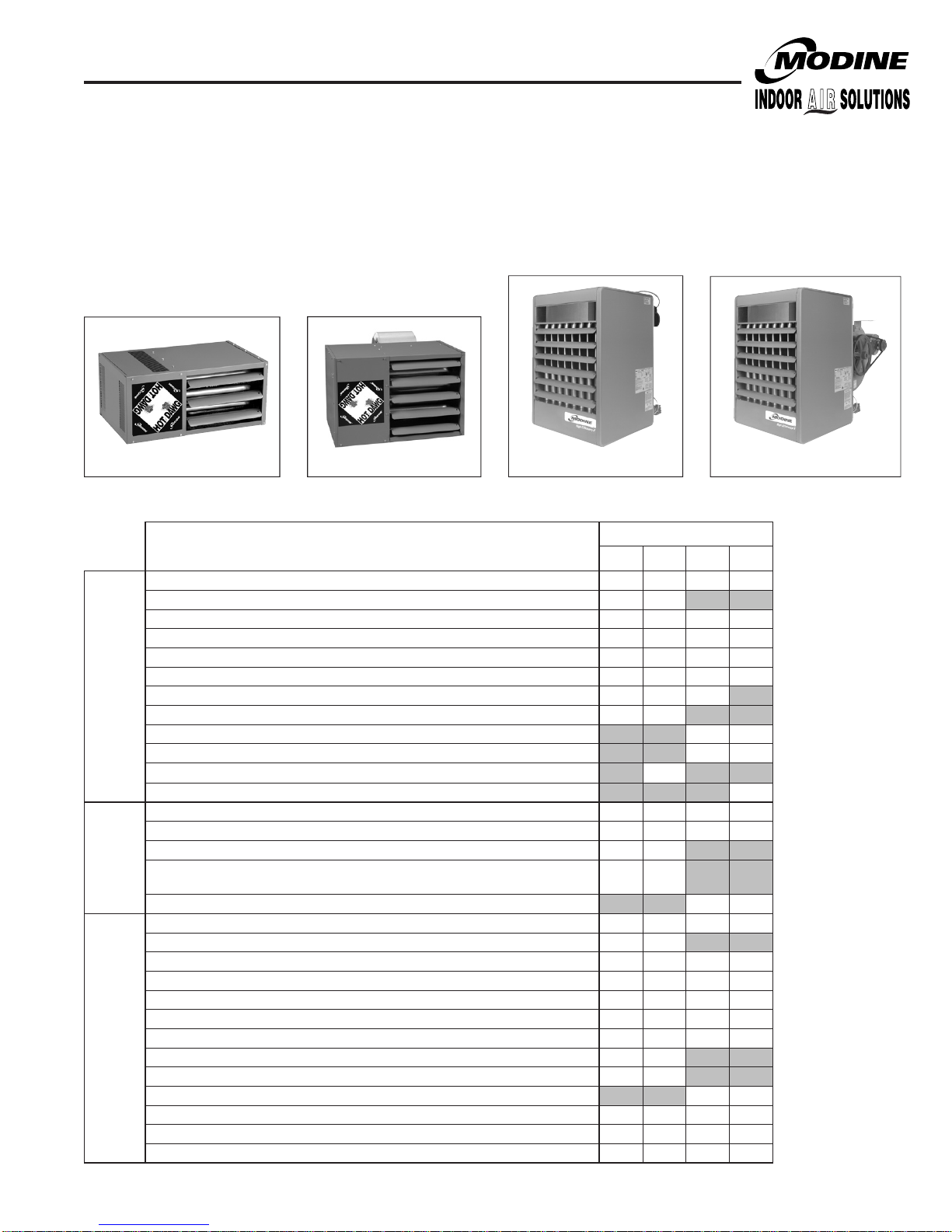
DESigN FEATURES - ALL UNiTS
Tubular Heat Exchanger Power Vented Unit
Heaters, 30-125MBH
For residential, commercial or industrial applications that require
a low profile unit, Modine offers the Hot Dawg®. Capable of
being installed just one inch below the ceiling, the superior
quality of the Hot Dawg makes it a preferred choice for a
variety of applications, including garages and workshops.
Figure 2.1 - Hot Dawg
Propeller Unit Heater
Model HD Model HDB
Table 3.1 - Standard Features and Factory Options ➀
Aluminized steel cabinet (gauge indicated)
Low profile casing design
Baked-on polyester powder paint for durability and corrosion resistence
Adjustable air-deflector blades
Fans engineered for quiet operation
Totally enclosed fan/blower motors (standard on sizes 100-400)
Fingerproof fan guard (optional on PDP units)
Two L-shaped mounting brackets (standard on sizes 30-75, accessory on sizes 100-125)
Adjustable mounting brackets for level hanging
Hinged tool-less bottom pan entry
Cabinet and Air Mover
Multi-tap 3-speed motors, certified to 0.8” W.C. external static pressure
Adjustable motor sheaves, certified to 0.5” W.C. external static pressure
80% thermally efficient
Aluminized steel heat exchanger (409 stainless steel optional)
Tubular heat exchanger
Heat
See page 13 for Field Installed Accessories
➀
In-shot burner on each heat exchanger tube for reliable performance, ease of
serviceability and low sound level on flame ignition/extinction
Exchanger
and Burner
Aluminized steel burner (409 stainless steel optional)
CSA certification for commericial and industrial use in the US and Canada
CSA certification for residential use in the US and Canada
Factory-installed power exhauster
Controls for natural gas (propane optional)
Single stage gas controls (two stage and mechanical modulation optional)
High limit safety control
Differential pressure switch for proof of venting
Flame roll-out safety switch
Controls
Direct spark ignition with continuous retry control system
Intermittent pilot ignition with continuous retry control system
Control terminal board and low voltage terminal connections
Gas control step down transformer with 24V gas controls
Fan delay timer
Figure 2.2 - Hot Dawg
Blower Unit Heater
Feature
6-189.5
Power Vented Unit Heater, 150-400MBH
For commercial or industrial applications that require higher
input ratings, the PDP/BDP is available in ratings that range
from 150,000 to 400,000 Btu/Hr in either natural or propane gas.
Figure 2.3 Propeller Unit Heater
Model PDP Model BDP
HD HDB PDP BDP
22 ga. 22 ga. 20 ga. 20 ga.
• •
• • • •
• • • •
• • • •
• • • •
• • •
• •
•
• • • •
• • • •
• •
• •
• • • •
• •
• • • •
• • • •
• • • •
• • • •
• • • •
• •
• •
• • • •
• • • •
• • • •
Figure 2.4 Blower Unit Heater
Model
• •
• •
•
• •
• •
3
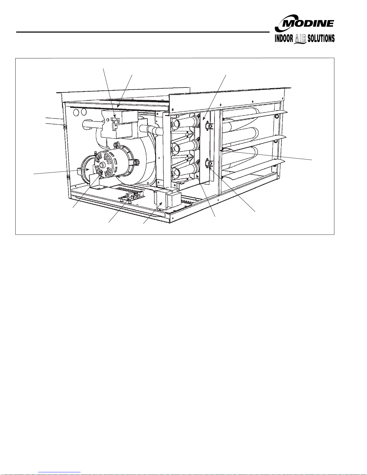
DESigN FEATURES - MODELS HD/HDB
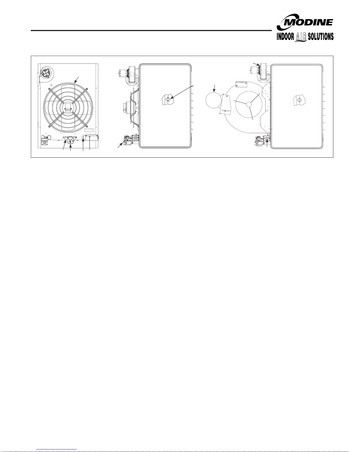
Figure 4.1 - Factory Mounted Standard and Optional Features (Models HD/HDB)
➁
➀
➃
➂
➉
➄
➈
➅
➇
➆
➀ Power Exhauster (STD)
All HD series (low profile) unit heaters are supplied with a
round vent pipe connection.
➁ Pressure Switch (STD)
An automatic reset vent pressure switch is supplied on
all HD series (low profile)unit heaters and is designed to
prevent operation of the main burner in the event there
is restricted venting of flue products. This restriction may
occur due to an improper vent diameter, long vent runs,
un-approved vent terminal, high winds, high negative
pressure within space, etc. After the cause of the
restriction has been corrected, the pressure switch will
reset automatically. See the trouble shooting section of the
installation and service manual for more information.
➂ integrated Direct Spark Control Board (STD)
The integrated direct spark ignition control combines all
furnace control functions. The integrated board provides
digital control of the air mover, inducer, ignition, gas valve
and flame sense as well as monitoring the safety circuit at
all times. The board includes LED diagnostics for trouble
shooting and a fused power supply.
➃ gas Valve - (See Table 12.2)
a) Single Stage gas Valve - (STD)
The main gas valve is factory installed on the unit
heater gas train. The main gas valve provides regulator,
main gas, and manual shutoff functions. The valve is
redundant and provides 100% shut off.
b) Two Stage gas Valve - (OPT)
The two-stage gas valve is factory installed on the unit
heater gas train. The two stage gas valve provides the
regulator, main gas (100% and 50% fire), and manual
shutoff functions. The valve is redundant and provides
100% shut off.
4
➄ Control Step Down Transformer - (STD)
The control step down transformer is located in the
electrical junction box. The transformer is used to step down
the supply power (115V, 208V, 230V, 460V, 575V) to 24V
for the gas controls, fan delay relay, field supplied motor
starter, etc. To determine the control transformer supplied
as well as any accessory/field supplied transformers
required, refer to Table 12.1
➅ Flame Sensor – (hidden, STD)
Remote flame sensor verifies ignition of all burners,
monitors the flame signal and communicates with the
integrated circuit board.
➆ Flame Roll Out Switch - (STD)
Flame roll out switches are mounted near the burners and
will shut off the gas supply in the event of an unsafe flame
roll out condition.
➇ Auto High Limit Switch - (hidden, STD)
The limit control is mounted in the air stream and will shut
off the gas supply in the event of overheating.
➈ Direct Spark igniter - (hidden, STD)
Provides spark for direct ignition of the burners.
➉ Manual Reset Control - (hidden, propeller 100-125 only)
6-189.5
DESigN FEATURES - MODELS PDP/BDP
Figure 5.1 - Factory Mounted Standard and Optional Features (Models PDP/BDP)
➉
➆
➅
➈
➁
➇
All units include the standard (STD) features, and may include
the optional (OPT) features shown.
➀ gas Valve (See Table 12.2)
a) Single Stage gas Valve - (STD)
The main gas valve is factory installed on the unit heater
gas train. The main gas valve provides the pilot, regulator,
main gas, and manual shutoff functions.
b) Two Stage gas Valve - (OPT)
The two-stage gas valve is factory installed on the unit
heater gas train. The two stage gas valve provides the
pilot, regulator, main gas (100% and 50% fire), and manual
shutoff functions. See the supplier literature included with
the unit.
c) Mechanical Modulating - (OPT)
Mechanical modulation utilizes a main gas valve as well
as a mechanical modulating gas valve (not shown).
The mechanical modulating valve includes a hydrostatic
sensing bulb that is to be field installed in ductwork. The
discharge air temperature is field set by the control dial on
the modulating gas valve. Refer to Installation and Service
manual for set point temperatures.
➁ ignition controller - (STD)
The ignition controller is factory installed on the back of the
unit heater with the spark igniter and sensor located on the
burner. For both natural and propane gas units, the ignition
controller is 100% shut-off with continuous retry. On a call for
heat, the system will attempt to light the pilot for 70 seconds.
If the pilot is not sensed for any reason, the ignition control
will wait for approximately six minutes with the combination
gas control closed and no spark. After six minutes, the cycle
will begin again. After three cycles, some ignition controllers
lockout for approximately one hour before the cycle begins
again. This will continue indefinitely until the pilot flame is
sensed or power is interrupted to the system.
➂ Time Delay Relay - (STD on all but Mech. Mod.)
The time delay relay is factory installed in electrical junction
box. The time delay relay allows the gas controls to operate
for approximately 30 to 90 seconds before the blower starts.
This allows the heat exchanger a warm up period so that the
initial delivered air is not cool. The time delay relay also keeps
the motor running for approximately 30 - 90 seconds after the
call for heat has been satisfied to remove the residual heat
from the heat exchanger.
Note: Mechanical modulation units are used on make-up air
only and do not require or include time delay relays.
➂
➄
➀
6-189.5
➃
➃ Low Voltage Terminal Board - (STD)
The low voltage terminal board is located in electrical junction
box. The terminal board is labeled to match the electrical
wiring diagram provided with the unit.
➄Control Step Down Transformer - (STD)
The control step down transformer is located in the electrical
junction box. The transformer is used to step down the supply
power (115V, 208V, 230V, 460V, 575V) to 24V for the gas
controls, fan delay relay, field supplied motor starter, etc.
To determine the control transformer supplied as well as any
accessory/field supplied transformers required, refer to
Table 12.1
➅Blower Motor - (OPT)
The blower motor is factory installed on the blower housing.
The blower motor can be provided in a variety of supply
voltages and motor horsepowers. The blower motor is
supplied with an adjustable sheave that can be used to
increase/decrease the blower RPM.
➆High Limit Switch - (STD)
The automatic reset high limit switch is factory installed on the
side of the unit heater. If the limit temperature is exceeded,
the gas controls are de-energized until the switch is cooled.
➇Pressure Switch (STD)
A automatic reset vent pressure switch is supplied on all
power vented unit heaters to prevent operation of the main
burner in the event there is restricted venting of flue products.
This restriction may occur due to an improper vent diameter,
long vent runs, un-approved vent terminal, high winds, high
negative pressure within space, etc. After the cause of the
restriction has been corrected, the pressure switch will reset
automatically.
➈Power Exhauster (STD)
All power vented unit heaters are supplied with a round vent
pipe connection. The power exhauster may be rotated 180° to
allow for various venting directions.
➉Finger Proof Fan guard (OPT)
Propeller units may be equipped with an optional finger proof
fan guard for added protection. The finger proof fan guard is
installed at the factory in place of the standard fan guard.
Standard fan guard is shown.
5

gENERAL PERFORMANCE DATA - MODELS HD & PDP
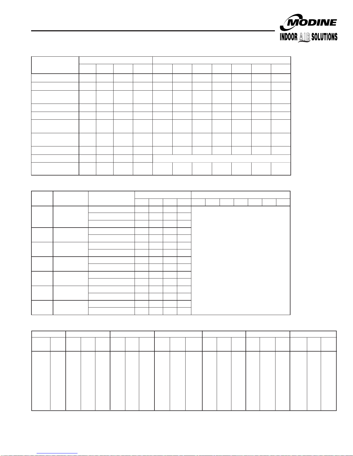
Table 6.1 - Propeller Unit Model HD and PDP general Performance Data
Model HD Sizes Model PDP Sizes
30 45 60 75 100 125 150 175 200 250 300 350 400
Btu/Hr Input ➀
Btu/Hr Ouput ➀
Entering Airflow (CFM)
@ 70°F
Outlet Velocity (FPM) 523 725 653 769 565 747 931 959 819 1053 1123 1068 1016
Air Temp. Rise (°F) 44 46 45 48 50 47 51 51 52 50 50 53 54
Max. Mounting
Height (Ft.) ➁
Heat Throw (Ft.) @
Max Mtg Ht ➁
Motor Type ➂
Motor HP 1/15 1/15 1/12 1/12 1/12 1/8 1/8 1/6 1/6 1/3 1/2 3/4 3/4
Motor RPM 1550 1550 1625 1625 1050 1625 1625 1075 1075 1075 1075 1125 1125
30,000 45,000 60,000 75,000 100,000 125,000 150,000 175,000 200,000 250,000 300,000 350,000 400,000
24,000 36,000 48,000 60,000 80,000 100,000 120,000 140,000 160,000 200,000 240,000 280,000 320,000
505 720 990 1160 1490 1980 2180 2550 2870 3700 4460 4870 5440
10 10 12 14 12 16 16 17 15 19 21 20 19
25 27 36 38 42 56 55 59 51 67 74 70 69
SP SP PSC PSC SP PSC PSC PSC PSC PSC PSC PSC PSC
Table 6.2 - Propeller Unit Model HD and PDP Operating Electrical Data
Supply
Voltage
115V
115V
1 Phase Total Amps 3.7 3.7 2.5 2.5 4.7 4.2 4.0 5.1 5.1 7.7 9.8 11.1 11.1
1 Phase
208V
1 Phase
230V
1 Phase
208V
3 Phase 208V Total Amps 2.05 2.05 1.38 1.38 2.60 2.32 2.21 2.82 2.82 4.26 5.42 6.14 6.14
230V
3 Phase 230V Total Amps 1.85 1.85 1.25 1.25 2.35 2.10 2.00 2.55 2.55 3.85 4.90 5.55 5.55
460V
3 Phase 460V Total Amps 0.93 0.93 0.63 0.63 1.18 1.05 1.00 1.28 1.28 1.93 2.45 2.78 2.78
575V
3 Phase 575V Total Amps 0.74 0.74 0.50 0.50 0.94 0.84 0.80 1.02 1.02 1.54 1.96 2.22 2.22
Ratings shown are for elevations up to 2,000 ft. For elevations above 2,000 feet, ratings should be reduced at the rate of 4% for each 1,000 feet above sea level. (In Canada see rating plate.)
➀
Reduction of ratings requires use of a high altitude kit.
Data taken at 55°F air temperature rise. At 65°F ambient and unit fired at full-rated input. Mounting height as measured from bottom of unit, and without deflector hoods.
➁
All motors used are produced, rated and tested by reputable manufacturers in accordance with NEMA standards and carry the standard warranty of both the motor manufacturer and Modine.
➂
All motors are 115V single phase motors with built-in thermal overload protection. Model sizes 30-75 are open motors, sizes 100-400 are totally enclosed.
Power Code
01 (115V)
01 (115V) with
Transformer
03 (208V)
01 (115V) with
Transformer
02 (230V)
01 (115V) with
Transformer
01 (115V) with
Transformer
01 (115V) with
Transformer
01 (115V) with
Transformer
30 45 60 75 100 125 150 175 200 250 300 350 400
Motor Amps 2.4 2.4 1.2 1.2 2.7 2.2 2.3 2.7 2.7 5.4 7.5 8.8 8.8
Transformer kVA n/a n/a n/a n/a n/a n/a n/a n/a n/a n/a n/a n/a n/a
Transformer kVA 0.5 0.5 0.5 0.5 1.0 1.0 0.5 1.0 1.0 1.0 1.5 1.5 1.5
208V Total Amps 2.05 2.05 1.38 1.38 2.60 2.32 2.21 2.82 2.82 4.26 5.42 6.14 6.14
Motor Amps
Total Amps 1.9 2.8 2.8
Transformer kVA 0.5 0.5 0.5 0.5 0.75 0.75 0.5 0.75 0.75 1.0 1.5 1.5 1.5
230V Total Amps 1.85 1.85 1.25 1.25 2.35 2.10 2.00 2.55 2.55 3.85 4.90 5.55 5.55
Motor Amps
Total Amps 1.9 2.8 2.8 3.7 4.7 5.5 5.5
Transformer kVA 0.5 0.5 0.5 0.5 1.0 1.0 0.5 1.0 1.0 1.0 1.5 1.5 1.5
Transformer kVA 0.5 0.5 0.5 0.5 0.75 0.75 0.5 0.75 0.75 1.0 1.5 1.5 1.5
Transformer kVA 0.5 0.5 0.5 0.5 0.75 0.75 0.5 0.75 0.75 1.0 1.5 1.5 1.5
Transformer kVA 0.5 0.5 0.5 0.5 0.75 0.75 0.5 0.75 0.75 1.0 1.5 1.5 1.5
n/a n/a n/a n/a n/a n/a
n/a n/a n/a n/a n/a n/a
Model HD Sizes Model PDP Sizes
1.0 1.5 1.5
1.0 1.5 1.5 2.5 3.5 4.4 4.4
n/a n/a n/a n/a
6
6-189.5
gENERAL PERFORMANCE DATA - MODELS HDB & BDP
Table 7.1 - Blower Unit Model HDB and BDP general Performance Data
Model HDB Sizes Model BDP Sizes
60 75 100 125 150 175 200 250 300 350 400
Btu/Hr Input ➀ 60,000 75,000 100,000 125,000 150,000 175,000 200,000 250,000 300,000 350,000 400,000
Btu/Hr Ouput ➀ 48,000 60,000 80,000 100,000 120,000 140,000 160,000 200,000 240,000 280,000 320,000
Entering Airflow
Range (CFM)
Outlet Velocity (FPM) 437-726 546-908 443-781 488-773 869 892 773 966 1026 1037 1008
Air Temp. Rise (°F) 40-70 40-70 35-65 45-75 40-70 40-70 40-70 40-70 40-70 40-70 40-70
Max. Mounting
Height (Ft.) ➁ 7-13 7-16 8-19 8-17 14 15 13 16 18 19 19
Heat Throw (Ft.) @
Max Mtg Ht ➁ 20-45 24-57 27-68 27-59 49 52 47 58 64 67 68
Motor Type ➂ P.S.C. P.S.C. P.S.C. P.S.C. T.E T.E T.E T.E T.E T.E T.E
Motor HP 1/4 1/3 1/2 1/2
Motor RPM
Table 7.2 - Blower Unit Model HDB Operating Electrical Data
Supply
Voltage
115V
115V
1 Phase Total Amps 6.4 8.1 11.5 11.5
1 Phase
208V
1 Phase
230V
1 Phase
208V
208V
3 Phase
3 Phase 208V Total Amps 3.54 4.48 6.36 6.36
230V
230V
3 Phase
3 Phase 230V Total Amps 3.20 4.05 5.75 5.75
460V
460V
3 Phase
3 Phase 460V Total Amps 1.60 2.03 2.88 2.88
575V
575V
3 Phase
3 Phase 575V Total Amps 1.28 1.62 2.30 2.30
Power Code
01 (115V)
01 (115V) with
Transformer
01 (115V) with
Transformer
01 (115V) with
Transformer
01 (115V) with
Transformer
01 (115V) with
Transformer
01 (115V) with
Transformer
635-
794-
1111
1389
Max
1100
1100 Max 1100 Max 1100
Max
1140-
2116
1235-
2058
1587-
2778
1725 1725 1725 1725 1725 1725 1725
Model HDB Sizes Model BDP Sizes
60 75 100 125 150 175 200 250 300 350 400
Motor Amps 5.4 7.1 9.5 9.5
Transformer kVA n/a n/a n/a n/a
Transformer kVA 1.0 1.0 1.5 1.5
208V Total Amps 3.54 4.48 6.36 6.36
Transformer kVA 1.0 1.0 1.5 1.5
230V Total Amps 3.20 4.05 5.75 5.75
Transformer kVA 1.0 1.0 1.5 1.5
Transformer kVA 1.0 1.0 1.5 1.5
Transformer kVA 1.0 1.0 1.5 1.5
Transformer kVA 1.0 1.0 1.5 1.5
1852-
3241
2116-
3704
See Table 9.1
2646-
4630
See Table 7.3
3175-
5556
3704-
6481
4233-
6584
Table 7.3 - Blower Unit Model BDP Operating Electrical Data
Voltage 115/60/1 230/60/1 208/60/3 230/60/3 460/60/3 575/60/3
Motor Motor Total Total Motor Total Total Motor Total Total Motor Total Total Motor Total Total Motor Total Total
HP Rpm Amps Amps Watts Amps Amps Watts Amps Amps Watts Amps Amps Watts Amps Amps Watts Amps Amps Watts
1/4 1725 3.7 6.0 696 2.7 4.0 914 1.3 2.6 539 1.2 2.5 569 0.7 1.9 592 0.5 1.8 569
1/3 1725 5.0 7.3 845 2.5 3.8 868 1.2 2.5 518 1.2 2.5 569 0.6 1.9 569 0.8 2.1 753
1/2 1725 8.0 10.3 1190 4.0 5.3 1213 2.2 3.5 726 2.1 3.4 776 1.1 2.4 799 0.9 2.2 811
3/4 1725 11.0 13.3 1535 5.4 6.7 1535 2.8 4.1 851 2.7 4.0 914 1.4 2.6 937 1.1 2.3 926
1 1725 13.4 15.7 1811 6.7 8.0 1834 3.6 4.9 1018 3.5 4.8 1098 1.8 3.0 1121 1.5 2.6 1127
1-1/2 1725 15.2 17.5 2018 7.6 8.9 2041 4.8 6.1 1267 4.8 6.1 1397 2.4 3.6 1397 1.9 3.1 1386
2 1725 --- --- --- --- --- --- 6.8 8.1 1683 6.0 7.3 1673 3.0 4.3 1673 2.3 3.5 1616
3 1725 --- --- --- --- --- --- 9.9 11.2 2328 8.2 9.5 2179 4.1 5.4 2179 3.4 4.6 2248
5 1725 --- --- --- --- --- --- 15.2 16.5 3430 13.0 14.3 3283 6.5 7.8 3283 5.3 6.5 3341
Ratings shown are for elevations up to 2,000 ft. For elevations above 2,000 feet, ratings should be reduced at the rate of 4% for each 1,000 feet above sea level. (In Canada see rating plate.)
➀
Reduction of ratings requires use of a high altitude kit.
Data taken at 55°F air temperature rise. At 65°F ambient and unit fired at full-rated input. Mounting height as measured from bottom of unit, and without deflector hoods.
➁
All motors used are produced, rated and tested by reputable manufacturers in accordance with NEMA standards and carry the standard warranty of both the motor manufacturer and Modine.
➂
All motors are 115V single phase motors with built-in thermal overload protection. Model sizes 60-75 are open motors, sizes 100-400 are totally enclosed.
6-189.5
7
 Loading...