

Modine Manufacturing Atherion MPR, Atherion ERM Service Manual
MCP15-525.0
MODINE CONTROL SYSTEM MANUAL
5H0837230000
September, 2012
commercial packaged ventilation system
Models MPR and ERM
WARNING IMPORTANT
1. Improper installation, adjustment, alt erat i on,
service or maintenance can cause property
damage, injury or death. Read the installat ion,
operating and maintenance instructions
thoroughly before installing or servicing thi s
equipment.
2. Improper control adjustments and manual
mode control can cause property damage,
injury or death. Read the installation,
operating and maintenance instructions
thoroughly before making adjustments.
3. Disconnect power supply before installing t he
accessory to prevent the unit from operating
during installation.
1. The use of this manual is specifically intended
for a qualified installation and service agency.
All installation and service of this unit must be
performed by a qualified installation and
service agency.
2. These instructions must also be used in
conjunction with the Installation and Service
Manual originally shipped with the appliance,
in addition to any other accompanying
component supplier literature.
3. This manual applies to Modine Control
System program version series 3 and 4 only.
For any other version, please contact Modine.
The program version that resides in the unit
controller can be found in the Information
section of the Service Sub Menu. Refer to the
manual for instructions on accessing this
screen.
THIS MANUAL IS THE PROPERTY OF THE OWNER.
PLEASE BE SURE TO LEAVE IT WITH THE OWNER WHEN YOU LEAVE THE JOB.

MODINE CONTROL SYSTEM MANUAL
Models MPR & ERM
2
MCP15-525.0
General Information
Controls are one of the most important c omponents of specialized HVAC equipment. The Modine Control System is designed
and engineered around the design of t he A therion™ to ensure that the unit operates safely, reliably, with optimized performance,
and maintaining maximum energ y ef ficiency.
Table of Contents
Model Nomenclature – Model MPR ............................................................. 4
Model Nomenclature – Model ERM ............................................................. 5
Identification of Superheat Cont rol..................................................................................................... 6
Controller Overview ...................................................................................... 7
Description and Features ................................................................................................................... 7
Standard and Optional Sensors Monitored ........................................................................................ 8
PCO3 Controller Layout ..................................................................................................................... 9
Display/Keypad Functions ......................................................................... 10
Standard Buttons ............................................................................................................................. 10
Extra Function Button Sequences ................................................................................................... 10
Menu Navigation .............................................................................................................................. 11
Navigation Sub Menus ..................................................................................................................... 11
Example Navigation to On/Off Sub Menus ...................................................................................... 11
Password Protection ........................................................................................................................ 12
Adjusting Customer Control Settings ............................................................................................... 12
Main Menu – Tree of Functions ................................................................. 13
Main Status Screen ..................................................................................... 14
Main Status Screen Parameters ...................................................................................................... 14
On/Off Sub Menu ......................................................................................... 18
Setpoint Sub Menu ..................................................................................... 19
Clock/Scheduler Sub Menu ........................................................................ 22
Input / Output Sub Menu ............................................................................ 23
Analog Inputs: .................................................................................................................................. 23
Digital Inputs: ................................................................................................................................... 23
Analog Outputs: ............................................................................................................................... 24
Digital Relay Outputs: ...................................................................................................................... 24
Data Logger Sub Menu ............................................................................... 25
Board Switch Sub Menu ............................................................................. 25
Programming the Remote Display Keypad to the Controller ........................................................... 26
Service Sub Menu ....................................................................................... 27
Information ....................................................................................................................................... 27
Working Hours ................................................................................................................................. 28
BMS Configuration ........................................................................................................................... 29
Working Hour Setpoint ..................................................................................................................... 30
Probe adjustment............................................................................................................................. 30
Control Settings ............................................................................................................................... 31
User DEV/Change PW1 .................................................................................................................. 39
Manual Management ....................................................................................................................... 40

MODINE CONTROL SYSTEM MANUAL
Models MPR & ERM
MCP15-525.0
3
Manual Control Reset ...................................................................................................................... 40
Analog Input: .................................................................................................................................... 40
Digital Input: ..................................................................................................................................... 41
Relay Output: ................................................................................................................................... 41
Analog Output: ................................................................................................................................. 41
Manufacturer Sub Menu ............................................................................. 42
Configuration .................................................................................................................................... 42
I/O Configuration – Digital Inp ut Configuration ................................................................................. 51
I/O Configuration – Analog Input Configuration ................................................................................ 56
I/O Configuration – Relay Output C onfiguration: .............................................................................. 63
I/O Configuration – Analog Output Configuration ............................................................................. 66
ERM ................................................................................................................................................. 67
Initialization ...................................................................................................................................... 70
pAD Settings .................................................................................................................................... 70
EVO -EVD Settings (Electronic Expansion Valve Driver) ................................................................. 73
Digital Scroll Compressors ........................................................................ 78
Starting Frequency and Minimum Compressor Running Time ......................................................... 78
Digital Scroll Compressor Operation ................................................................................................ 78
Electronic Expansion Valves Carel CDSS Mode ...................................... 79
Unit Alarms ................................................................................................. 80
Main Unit Controller Inputs/Outputs ......................................................... 83
pCO3 Inputs ...................................................................................................................................... 83
pCO3 Outputs ................................................................................................................................... 84
pCOe Expansion Module Inputs/Outputs (for Emerson EC3 Superheat Control only) ..................... 85
EVO/EVD Driver Module Inputs/Outputs (for Carel EVD Superheat Control only) ........................... 85
Energy Recovery Module Controller Inputs/Outputs (if equipped) ........ 86
pCOxs Inputs ................................................................................................................................... 86
pCOxs Outputs ................................................................................................................................. 86
Typical BMS – EMS – BAS System Variables .......................................... 87

MODINE CONTROL SYSTEM MANUAL
Models MPR & ERM
4
MCP15-525.0
Model Nomenclature – Model MPR
1, 2, 3 4, 5 6 7 8 9 10 11 12 13 14 15 16 17 18 19 20
UT UNC CS AC EC CMP HGR CA SB HP MT SV SA HT UNH TR HC
Digits 1, 2, 3 - Unit Type (UT)
MPR - Commercial Packaged Ventilation Unit
Digits 4, 5 - Unit Nominal Cooling (UNC)
15 - 15 ton
20 - 20 ton
26 - 26 ton
30 - 30 ton
6 - Cabinet Size (CS)
C - "C" Cabinet
7 - Air Control Configuration (AC)
A - Fresh & Return Air Dampers
D - Fresh Air Dampers (no Return Air)
E - Fresh Air Dampers (with Exhaust Air Opening and
Interface to Energy Recovery Module)
F - Fresh Air Dampers (with Exhaust Air Opening and
Interface to Power Exhaust Module)
G - Return Air Opening only (No Dampers or Fresh Air)
8 - Evaporator Coil (EC)
1 - High Capacity 4 Row, 14fpi DX Coil
2 - High Capacity 4 Row, 14fpi DX Coil with E-Coat
9 - Compressor Staging (CMP)
A - Tandem Digital Scroll Compressor
10 - Hot Gas Reheat (HGR)
0 - No Hot Gas Reheat
1 - Modulating Hot Gas Reheat
2 - Modulating Hot Gas Reheat with E-Coat
11 - Condenser Arrangement (CA)
A - Standard Fans, VFD Control, Microchannel Coils
B - Standard Fans, VFD Control, Microchannel Coils
with E-Coat and UV Top Coat
12 - Supply Blower Configuration (SB)
3 - 20" Backward Inclined Airfoil Plenum Fan
5 - 25” Backward Inclined Airfoil Plenum Fan
6 - 28" Backward Inclined Airfoil Plenum Fan
13 - Supply Blower Motor HP (HP)
C or Q - 1hp
D or R - 1-1/2hp
E or S - 2hp
F or T - 3hp
G o r U - 5hp
H or V - 7-1/2hp
J or W - 10hp
K or X - 15hp
C thru K include a factory mounted/wired motor starter.
Q thru X are Variable Frequency Drive (VFD) ready.
14 - Supply Blower Motor Type (MT)
1 - ODP - NEMA Premium Efficiency
2 - TE - NEMA Premium Efficiency
15 - Unit Supply Voltage (SV)
4 - 208V/3ph
5 - 230V/3ph
6 - 460V/3ph
7 - 575V/3ph
16 - Supply Blower Sheave Assy (SA)
Refer to AccuSpec
17 - Heating Section Type (HT)
0 - None
1 - Electric
2 - Natural Gas
3 - Natural Gas with 20kW Aux Elec Heat
- Nominal kW rating, derated for 208V/3ph.
18 - Nominal Heat Capacity (UNH)
N - No Heating
A - 20kW Electric
B - 40kW Electric
C - 60kW Electric
D - 80kW Electric
E - 100kW Electric
J - 300 MBH Gas - 80%
K 400 MBH Gas - 80%
L - 500 MBH Gas - 80%
- Nominal kW rating, derated for 208V/3ph.
19 - Temperature Rise (TR)
N - Not Applicable
(300MBH Gas Only and Electric)
H - High Air Temp Rise (75°F and Higher)
(400 and 500 MBH Gas Only)
L - Low Air Temp Rise (Under 75°F)
(400 and 500 MBH Gas Only)
20 - Heat Control (HC)
N - No Heating
A - Single Stage (Electric Only)
B - Two Stage (Electric Only)
C - Four Stage (Electric Only)
D - Modulating (Gas or Electric)

MODINE CONTROL SYSTEM MANUAL
Models MPR & ERM
MCP15-525.0
5
Model Nomenclature – Model ERM
1, 2, 3 4, 5 6 7 8 9 10 11 12 13 14
UT NWD CS ERT EBP EBC HP MT SV SA PH
Digits 1, 2, 3 - Unit Type (UT)
ERM - Energy Recovery Module
Digits 4, 5 – Nominal Wheel Diameter (NWD)
48 - 48” (6000 CFM limit )
58 - 58” (8700 CFM limit)
6 - Cabinet Size (CS)
C - "C" Cabinet
7 – Energy Recovery Type (ERT)
T - Total Energy Recovery Wheel
8 – Economizer Bypass (EBP)
E - Economizer Bypass
9 – Exhaust Blower Configuration (EBC)
3 - 20" Backward Inclined Airfoil Plenum Fan
6 - 28" Backward Inclined Airfoil Plenum Fan
10 - Exhaust Blower Motor HP (HP)
C or Q - 1hp
D or R - 1-1/2hp
E or S - 2hp
F or T - 3hp
G o r U - 5hp
H or V - 7-1/2hp
J or W - 10hp
C thru J include a factory mounted/wired motor starter.
Q thru W are Variable Frequency Drive (VFD) ready.
11 - Exhaust Blower Motor Type (MT)
1 - ODP - NEMA Premium Efficiency
2 - TE - NEMA Premium Efficiency
12 - ERM Supply Voltage (SV) (must match base model MPR unit)
4 - 208V/3ph
5 - 230V/3ph
6 - 460V/3ph
7 - 575V/3ph
13 - Exhaust Blower Sheave Assy (SA)
Refer to AccuSpec
14 – Electric Preheat (PH)
0 - No Heating
A - 20kW Electric (Nominal kW rating, derated for 208V/3ph.)
MODINE CONTROL SYSTEM MANUAL
Models MPR & ERM
6
MCP15-525.0
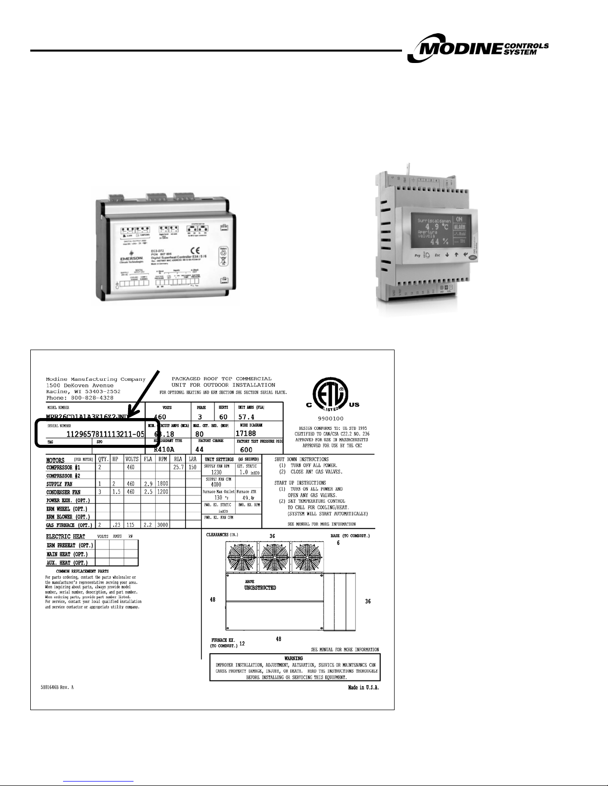
Identification of Superheat Control
This manual includes information that varies based on the superheat contr oll er used. The Atherion uses one of two dif ferent
superheat controllers. The controller can be identified in the unit serial number as follows:
If Digit 12=1, Emerson EC3 Superheat Control is used: If Digit 12=2, Carel EVD Superheat Control is used:
Sample Unit Serial Plate

MODINE CONTROL SYSTEM MANUAL
Models MPR & ERM
MCP15-525.0
7
Controller Overview
Description and Features
The Modine Control System utilizes a Carel pCO3 programmable microprocessor cont roller. Highly advanced with a powerful
microprocessor and fast processing speed, the controller features a hi gh number of I/O’s for complex HVAC/R applications.
The main controller board is housed in a plastic case that ensures a high index of protection and reduces the risk of electrostatic
discharges due to incorrect handling. The controller offers greater s afety due to the optical isolation of the serial pLAN, protection
of the analog inputs in the event of incorrect connections, and an extended range of operating temperatures. Given the increasing
demand for integration, pCO3 can interface with BMS systems via many of the most commonly-used serial communication
standards, using optional boards.
Some of the features of the Carel pCO3 programmable microprocessor controller include:
• 10 Analog Inputs
o Uses 10K NT C temperature sensors
o 4-20ma Humidity and CO2 sensors for reliability
• 6 Analog Outputs
o 0-10vdc for easy fault finding
• 18 Digital inputs
o Used to monitor all aspects of the unit
• 18 Digital Outputs
o True relayed outputs for reliability
• Real Time Clock
o With batt ery backup and day light savings adjustment
• pLAN Communication
o To allow connectivity to space sensors and o ther controllers
• Built In Display
o Backlit easy to use and easy to read
• Alarm Logging
o With a snapshot of the unit sensors
• Run Hours logging
o With maintenance setpoints
• Password Protection
o Three levels of password protection
• Manual Control
o For easy startup and service
• Simple Interface
o Easy to und er stand menus and settings
• Built in Scheduler
o Up to 7 periods per day – Either On/Off control or Occ upied/Unoccupied
o Holiday Scheduler with up to 20 holiday periods
• Remote Display option
o Can be 100ft from unit using standard RJ12 cable
• All reset points fully adjustable

MODINE CONTROL SYSTEM MANUAL
Models MPR & ERM
8
MCP15-525.0
Standard and Optional Sensors Monitored
The Modine Control System monitors a number of sensors within the Atheri on unit as follows:
Standard sensors monitored:
• Supply Air (Field Installed – see main unit Installation Manual)
o Main DOAS – HOAS control
• Outside Temperature (Unit Mounted) and Outside Humidity (Unit Mounted)
o Used to calculate OA enthalpy and dew point
• Suction Pressure (Unit Mounted)
o Used for superheat and dehumidification control
• Liquid Lin e Pr e ssure (Unit Mounted)
o Used for head pressure control
• Compressor High Pressure Switch (Unit Mounted)
o With retry control
• Compre ss or Low Pressure Switch (Unit Mounted)
o With retry control
• Supply Fan Air Proving Switch (Unit Mounted)
o Pressure differential switch
• Damper End Switch (Unit Mounted)
o Used to enab l e the supply fan
• Digital Compressor Alarm (Unit Mounted)
o Monitors the compressor protection and sup er heat modules
• Cooling Coil Condensate High Level Alarm (Unit Mounted)
o Disables the compressors if the drain pan is not draining properly
Optional sensors available:
• CO
• Building Pressure Sensor (Field Installed)
• Duct Pressure Sensor (Field Installed)
• Return Air Sensor (Unit Mounted)
• pAD Space Temperature and Humidity (Field Installed)
• Filter Dirty Switch (Unit Mounted)
Sensor (Field Installed)
2
o Used for demand ventilation control
o Used to control supply fan, exhaust fan, or dampers
o Used to control supply fan
o Only applicable if the unit has return air
o Used for spac e temperature and humidity control
o Pressure differential switch
MODINE CONTROL SYSTEM MANUAL
Models MPR & ERM
MCP15-525.0
9
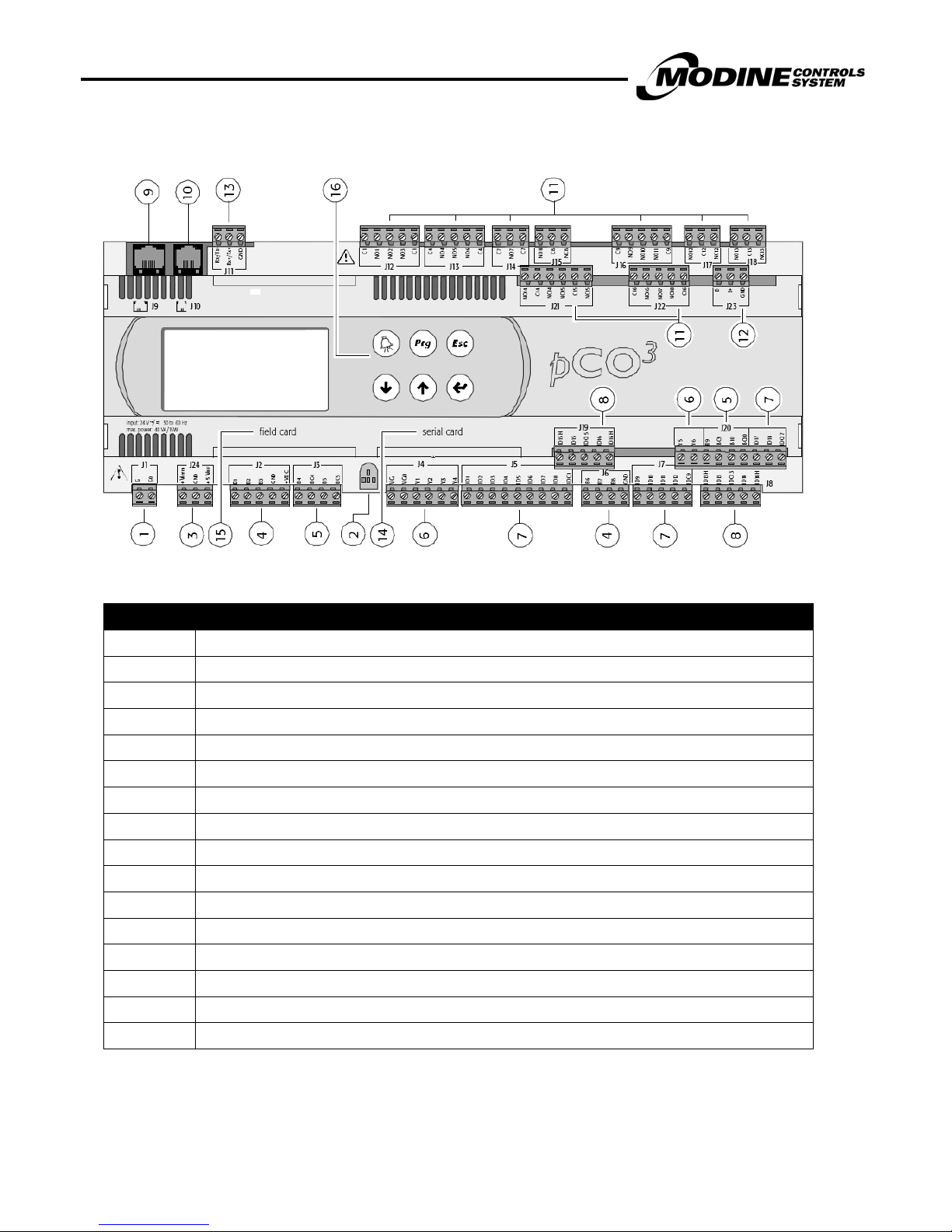
PCO3 Controller Layout
Reference Description
1 Power supply connector [G (+), G 0 (-)]
2 Yellow power LED and 3 status LEDs
3 Additional power supply for the t erminal and 0 to 5 V ratiometric probes
4 Universal analogue inputs: NT C, 0 to 1 V, 0 to 5 V ratiometric, 0 to 10 V, 0 to 20 mA, 4 to 20 mA
5 Passive analog inputs: NTC, PT 1000, ON/OFF
6 0 to 10 V analog outputs
7 24 Vac/Vdc digital inputs
8 230 Vac or 24 Vac/Vdc digital inputs
9 Connector for the display panel (exter nal panel with direct signals)
10 Connector for all standard pCO series terminals and for downloading the applicat i on program
11 Relay digital outputs
12 Connector for connection to the I/O expansion board
13 pLAN network connector
14 Cover for inserting the supervisor and maintenance option
15 Cover for inserting the field card option
16 Built-In terminal (LCD, buttons and LEDs)
MODINE CONTROL SYSTEM MANUAL
Models MPR & ERM
10
MCP15-525.0
Prg
Esc
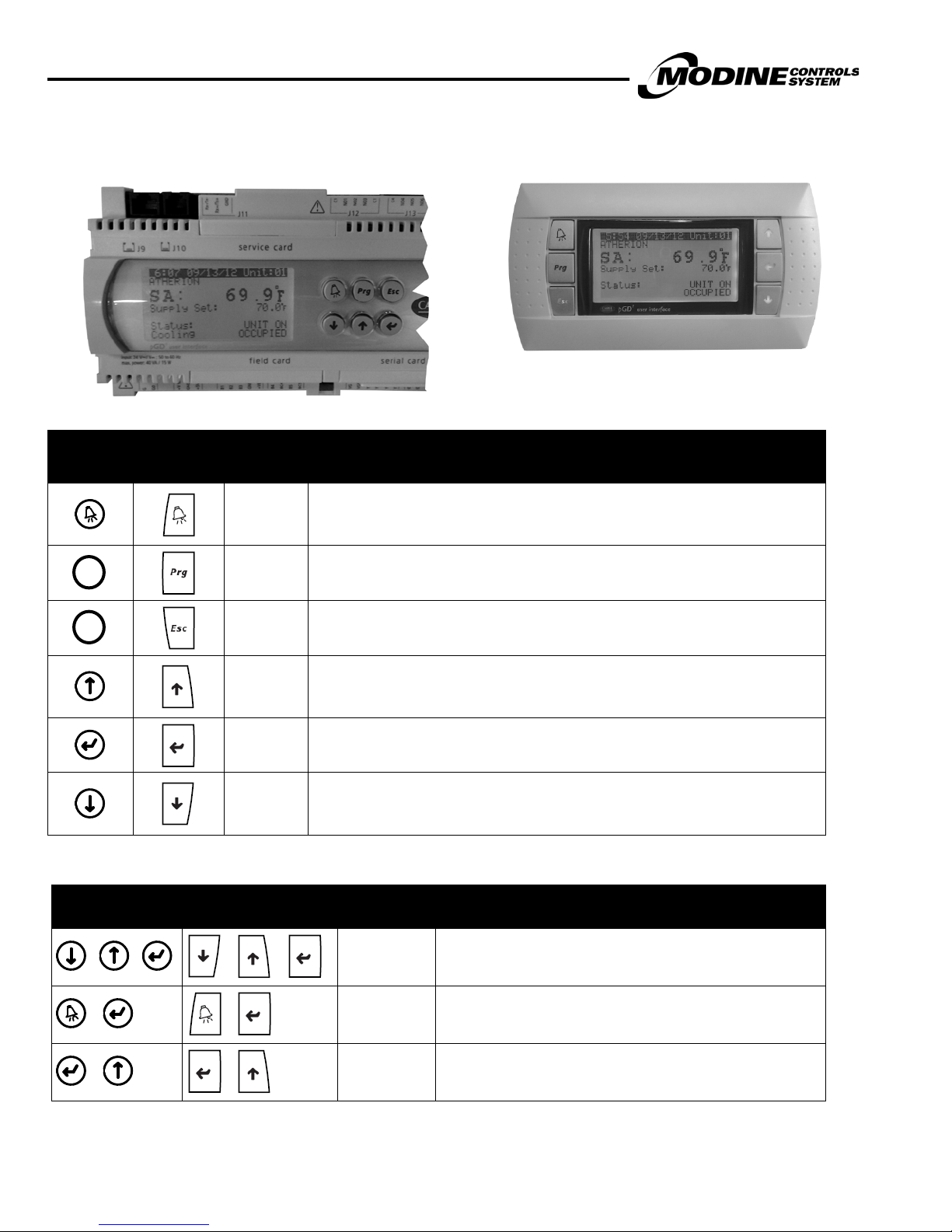
Display/Keypad Functions
pCO3 Display Keypad pGD1 Remote Display Keypad (Optional)
Standard Buttons
pCO3 Built-
in Display
pGD1
Remote
Display
Function Description
When one or more alarms are active the ALARM button will illuminate red.
ALARM
Pressing the ALARM button once will indicate information regarding any active alarms.
Pressing the ALARM button twice will reset any active manual-reset alarms.
Refer to Literature #MCP15-543 for installation instructions. Refer to
the Board Settings section for instructions on programming the remote
display keypad to the controller.
PRG Pressing the PRG button will select the main navigation menu.
ESC
UP
ENTER
DOWN
Pressing the ESC button will return the user to the main display screen showing unit
status.
Pressing the UP button can either:
Scroll through the various display screens, providing the cursor is in the top left position.
Increase the value of a set point adjustment.
Pressing the ENTER button will confirm any set point adjustments and move the cursor to
the next available set point.
Pressing the DOWN button can either:
Scroll through the various display screens, providing the cursor is in the top left position.
Decrease the value of a set point adjustment.
Extra Function Button Sequences
pCO3
Built-in Display
+ +
+
pGD1
Remote Display
.+. .+.
+
Combinations
UP + DOWN+
ENTER
ALARM +
ENTER
Key
Description
Allows access to controller address.
Allows access to controller system information.
+
+
ENTER + UP Change unit on remote display keypad. (ERM Only)
MODINE CONTROL SYSTEM MANUAL
Models MPR & ERM
MCP15-525.0
11
Prg
Prg
Esc
Menu Navigation
The following instructions ref er to the built-in display keypad buttons . See the table on the previous page for the corresponding
buttons if using the remote keypad.
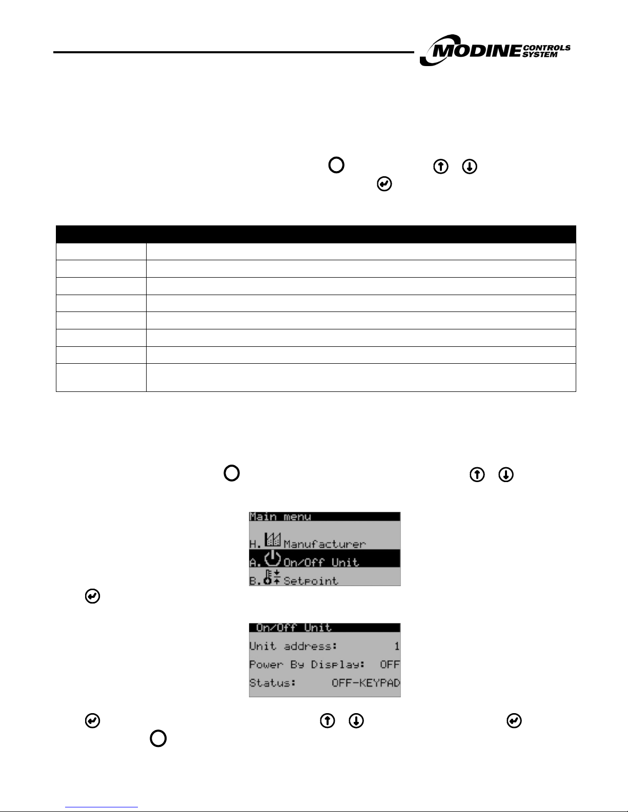
The Main Status Screen is displayed when the unit is first turned on or after one minute of keypad inactivity. Fr om this Main
Status Screen, eight sub menus can be accessed by pressing the button and using the or buttons t o move to the
desired menu. The selected menu will be highlighted with a black bar. Press to enter the selected menu.
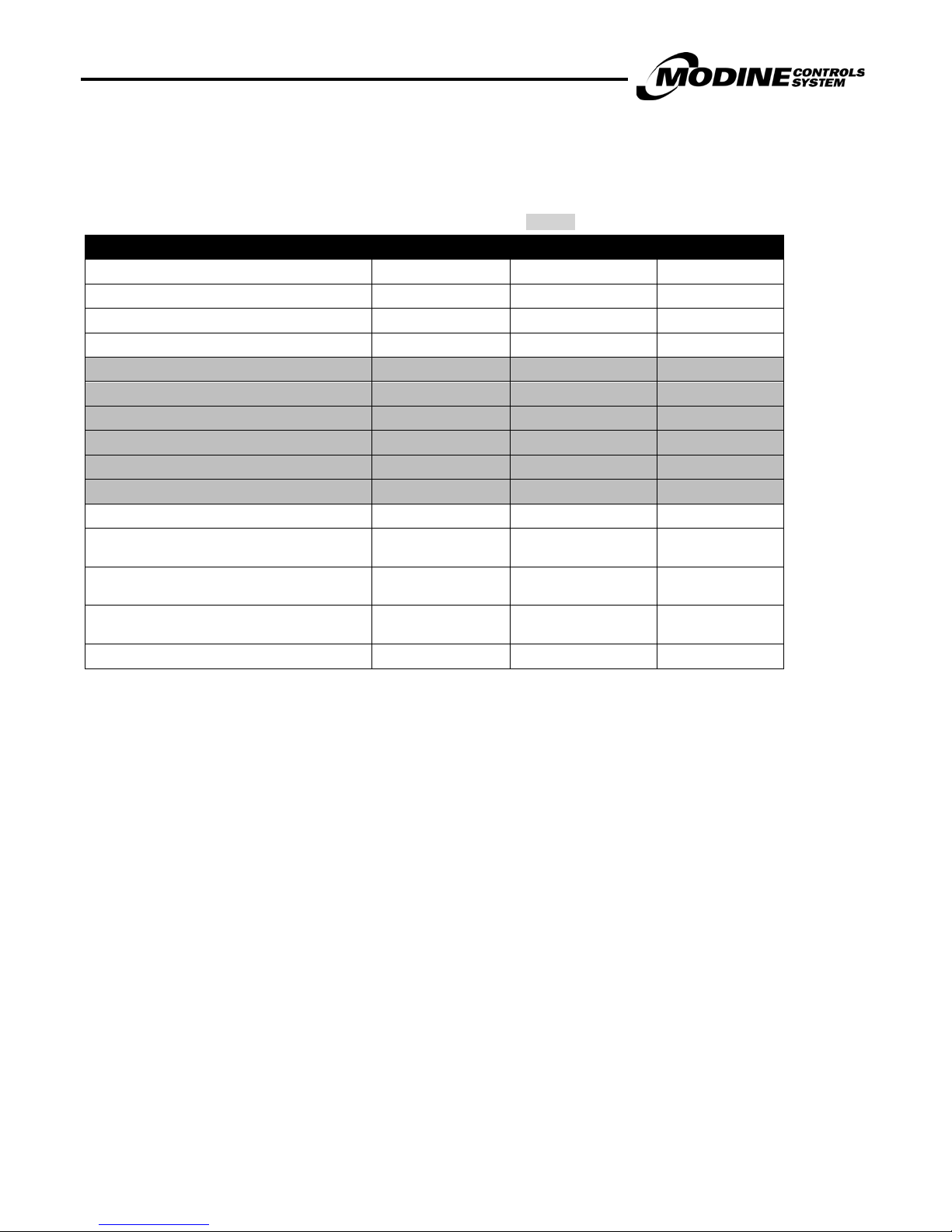
Navigation Sub Menus
Sub Menu Description
A. Unit On/Off
B. Setpoints
C. Clock/Scheduler
D. Input/Output
E. Alarm Log
F. Board Switch
G. Service
H. Manufacturer
Details on the Main Status Screen and each sub menu will be covered in the following sections of this manual.
Example Navigation to On/Off Sub Menus
(Similar for all other sub menus):
Switch on or switch off the unit.
View the user setpoints.
View the current time and date and set o n/off time zones.
View the status of the controller inputs and outputs.
View the alarm log.
Change the controller pLAN board address.
View maintenance related parameters, such as hours run, sensor calibration and manual overrides.
Manufacturer menu and adjustment of various manufacturer related parameters, such as unit
configuration and timing settings.
From the Main Status Screen, press the key to access the Sub Menu sele c tion screen. Use the or buttons to
navigate to the On/Off sub menu as shown in the following picture:
Press to access the On/Off sub menu screen:
Press to navigate to the parameter to chan ge, then use the or button to change the value. Press again to confirm
the setting. Press the button to exit the sub menu screen, back to the Main Status Screen.
MODINE CONTROL SYSTEM MANUAL
Models MPR & ERM
12
MCP15-525.0
Esc
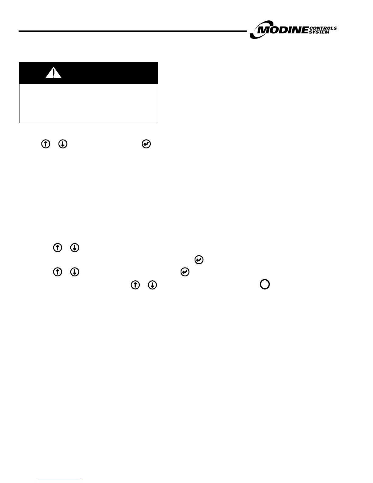
Password Protection
WARNING
Improper control adjustments and manual m ode
control can cause property damage, injury or
death. Read the installation, operating and
maintenance instructions thoroughly before
making adjustments.
To prevent unauthorized adjustments, a password is required to gain access to certain menus. When a password is requested
use the or keys to enter the number and to access the page. The passwords for the sub menus are as follows:
SETPOINTS: None
CLOCK/SCHEDULER: None
SERVICE SETTINGS: 0001
MANUFACTURER: Contact Modine
Adjusting Customer Control Settings
The following procedure is used to access and adjust control parameters (refer to Parameters List and Factory Values).
1. After entering the correct pas sword the cursor will appear at the top left corner (Home location).
2. Use the or keys to move to the desired menu.
3. To move the flashing cursor to the r equired adjustable fields press .
4. Use the or keys to change t he values and press the key to move the cursor to the next field or Home location.
5. When the cursor is Home either us e the or keys to scroll to the next sub-menu or the key to exit and return to
the Main Menu page.
MODINE CONTROL SYSTEM MANUAL
Models MPR & ERM
MCP15-525.0
13
Unit Sta tu s
A.
On/Off By Display
On/Off By pAD (Optional)
B.
Supply Air Setpint
Dampe r Mi n Position
Room Space Te m perature (Optional )
Room Space Humidi ty (Optional)
Building Pre ssure (Optional)
C.
Date/time
Daylight Savings
Scheduler
Holidays
D.
a. Ana log i nputs
b. Digital i nputs
c. Analog outputs
d. Digital outputs
E.
F.
G. Service
b. Information
d. Working Hours
e. BMS config.
f. S ervice S etti n g s
a. Working hours set
b. Probe adjustment
c. Control Settings
d. User Dev/Change PW 1
g. Manual Management
H. Manufacturer
a. Configuration
b. I/O Configuration
c. ERM (Optional)
d. Initialization
e. pAD settings (Optional)
To acces s the
branches i n t hi s
area, enter pass word
PW1
To acces s the
branches i n t hi s
area, enter pass word
PW2
Data Logge r
Board Swi tch
On/ Off Un it
Setpoints
Clock/Scheduler
Input/Output
Prg
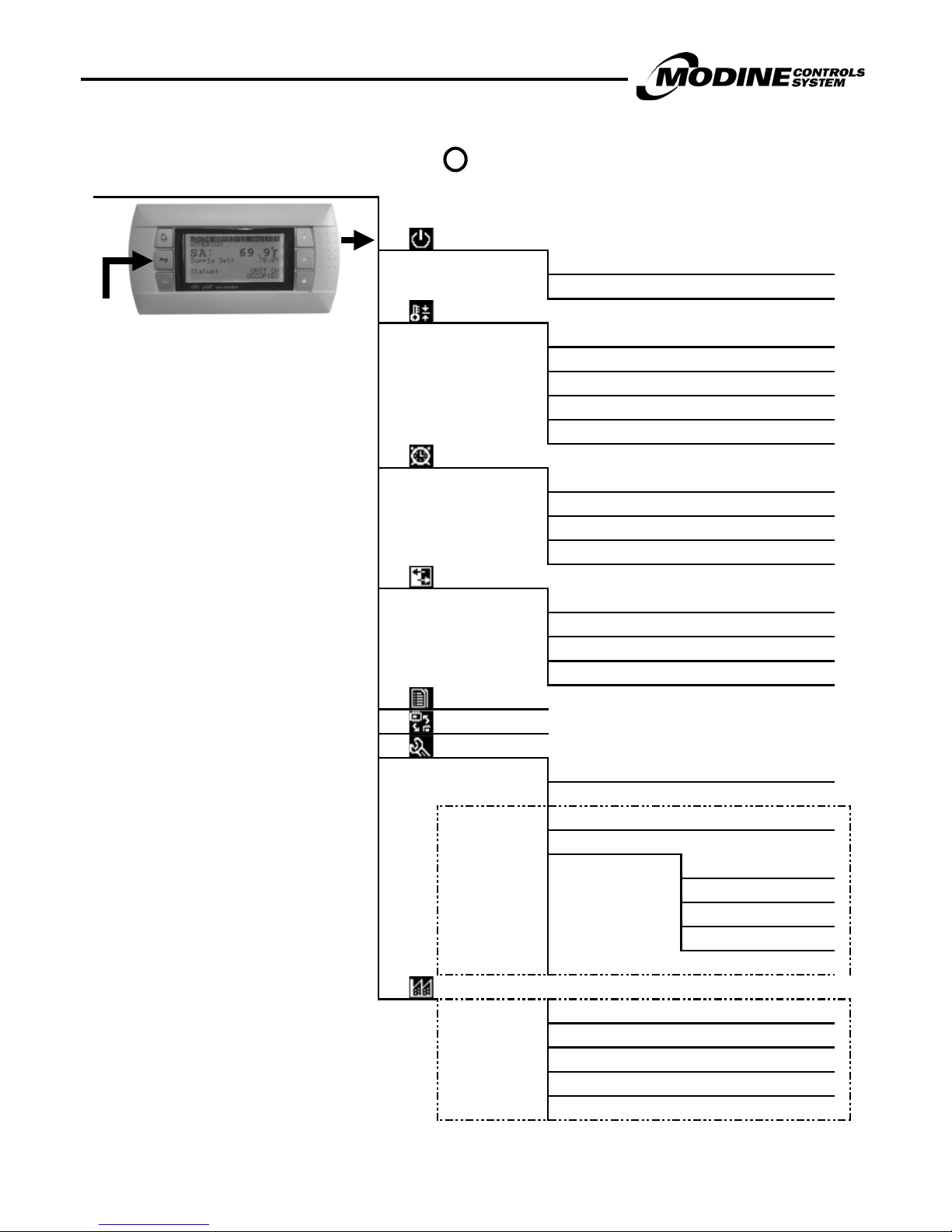
Main Menu – Tree of Functions
Irrespective of the current screen displayed, pressing the key accesses the main menu, as shown below:

MODINE CONTROL SYSTEM MANUAL
Models MPR & ERM
14
MCP15-525.0
Unit On
Wait Sup Fan
Unoccupied
Occupied
Dehum
Main Status Screen
The Main Status Screen is displayed when the unit is first turned on or after one minute of keypad inactivity.
The following information is displayed on t he Main Status Screen:
• Time/date
• Unit number
• Supply Air Temperature
• Current Supply Air Setpoint
• Unit Status
• Unit Mode
Once this screen is displayed, t he user can navigate up and down through the list of Main Status Screen Parameters by using the
+ buttons. These screens are described in further detail in the next sec tion.
Note that the main unit controller will always show as Unit: 01. If the unit i s al s o equipped with an ERM module, it has its own
controller, which is Unit: 02. The ke ypad at the main controller or the remote key pad can be used to change the Main Status
Screen to display either Unit 01 or 02.
To change the controller being disp l ayed, press the + buttons. If you are viewing the main controller display, pressing
those buttons will switch to displa ying the ERM controller. Pressing thos e buttons again will revert back t o displaying the main
controller.
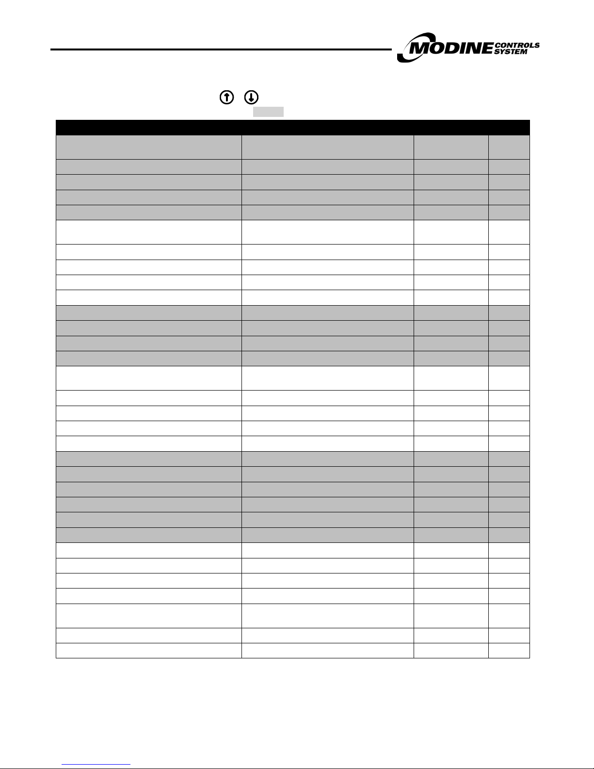
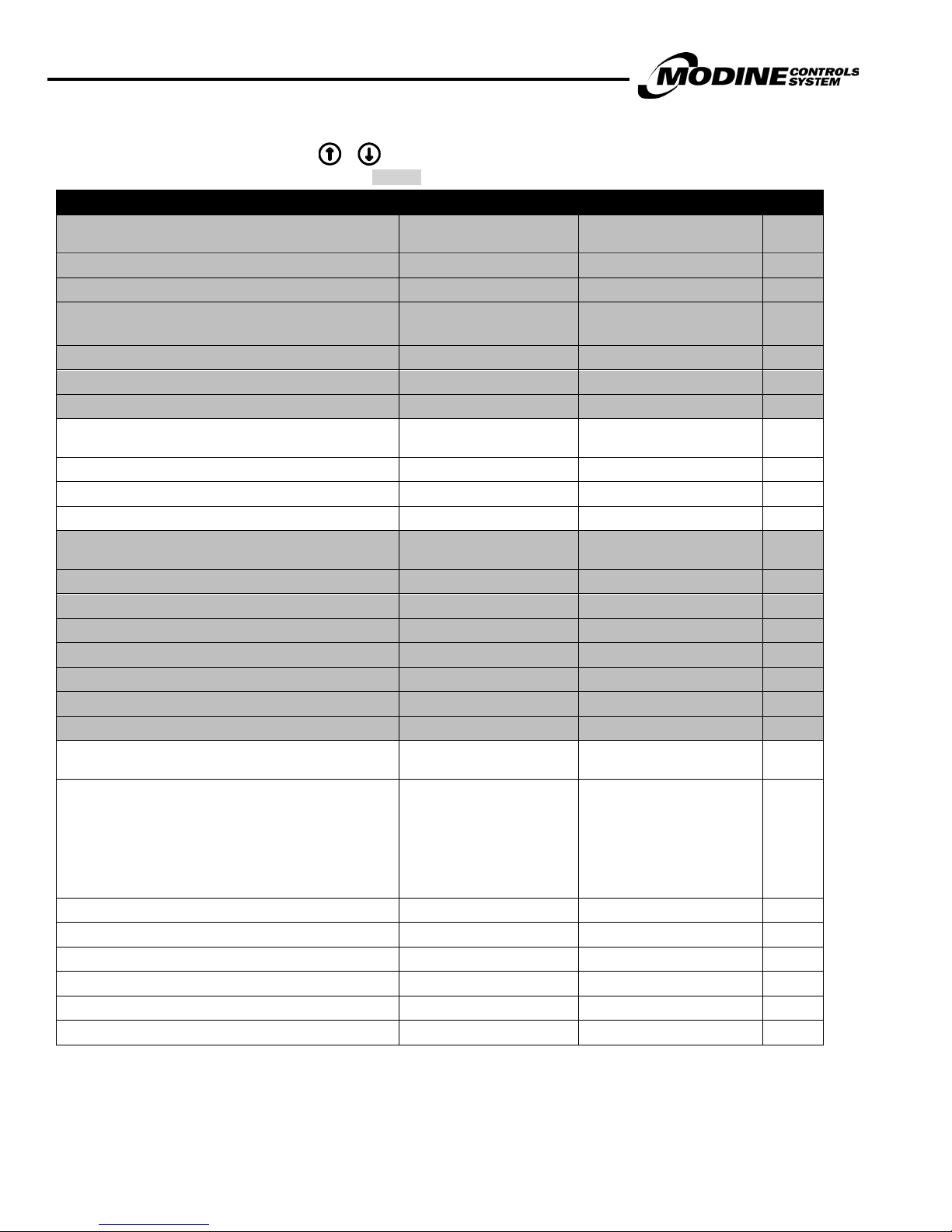
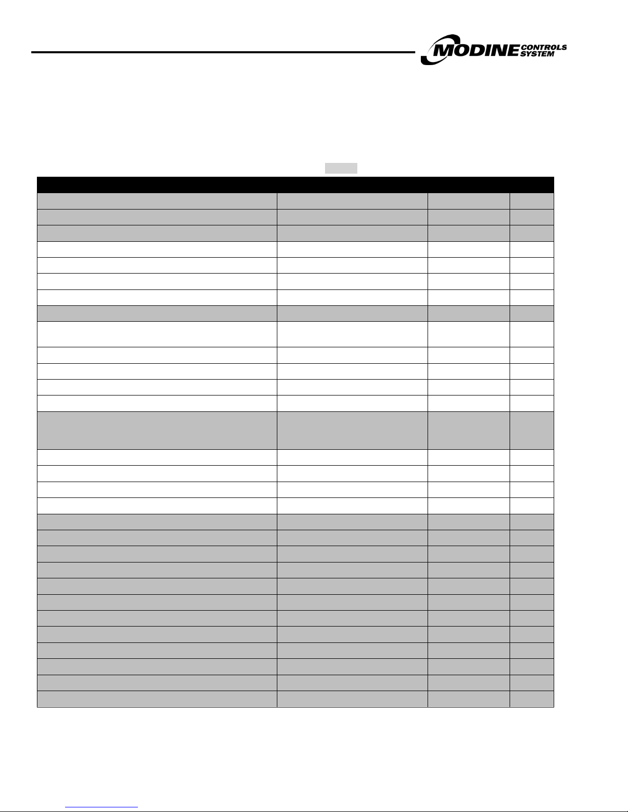
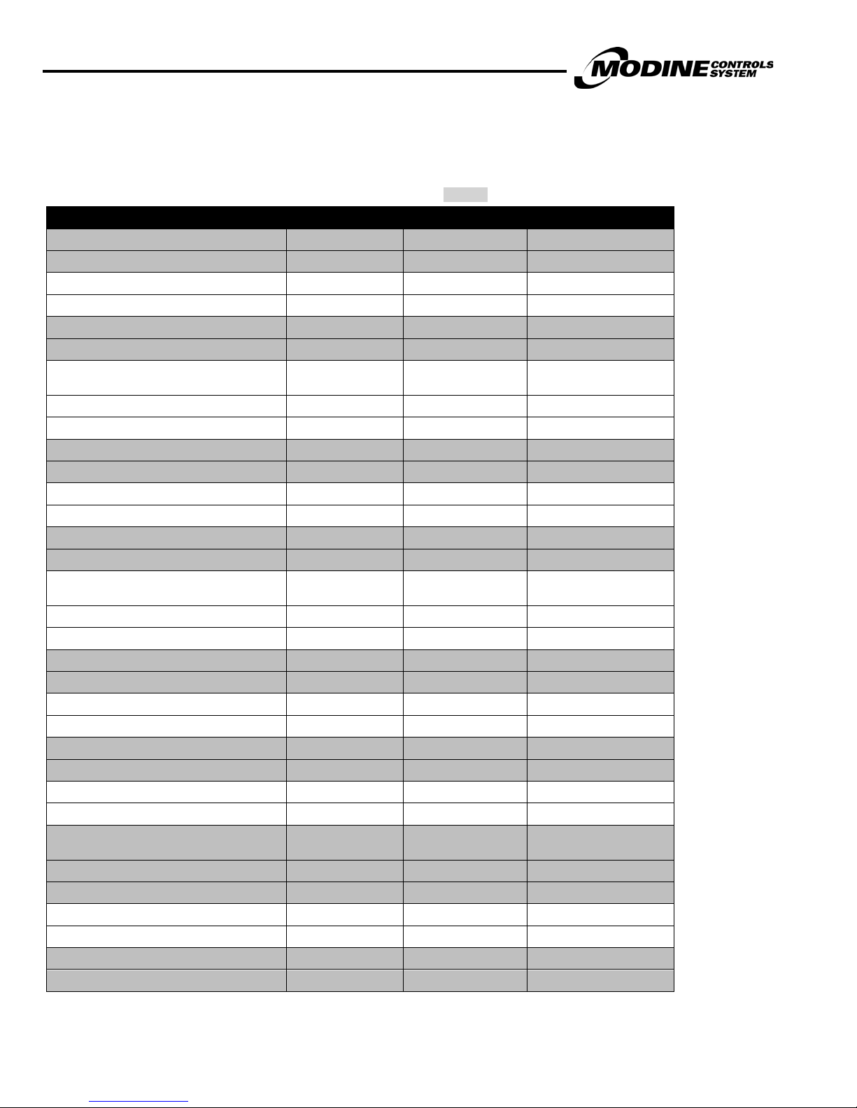
Main Status Screen Parameters
The status screens can be seen when the + buttons are pressed on the Main Status Screen. The following table
describes the menu parameters (Note: Change in shading indicates change to next screen):
PARAMETER DESCRIPTION FACTORY VALUE RANGE UNITS
Time and date Current time and date
Unit network address Actual Value 1
Supply Air Temperature Actual Value °F / °C
Supply Air Setpoint Actual Value °F / °C
OFF by Alarm
OFF by pLAN
OFF by BMS
OFF by Clock
Unit Status Current status of unit
Current Occupied Mode
Occupied Mode
Unit Mode Current Mode of operation
Note: Unless a pAD Wall Stat is installed the
unit only operate in Occupied Mode
OFF by Digital In
OFF by Keypad
OFF by Demand
OFF - Door Open
Off Manually
Wait - Damper
Occupied – BMS
Occupied – CLK
Occupied – DIG
Venting
Cooling
Heating
(continued on next page)
MODINE CONTROL SYSTEM MANUAL
Models MPR & ERM
MCP15-525.0
15
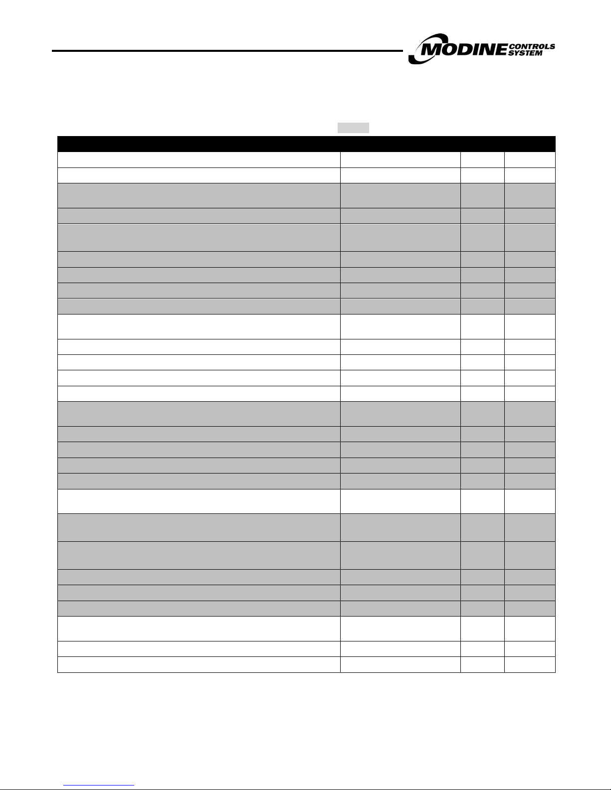
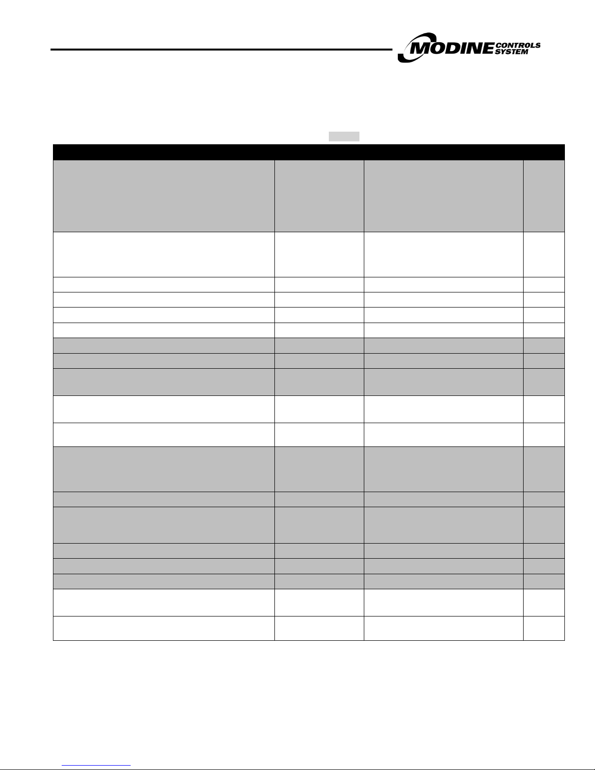
Main Status Screen Parameters (continued)
The status screens can be seen when the + buttons are pressed on the main status screen. The following table
describes the menu parameters (Note: Change in shading indicates change to next screen):
PARAMETER DESCRIPTION FACTORY VALUE RANGE UNITS
Note: The screen below will only be displayed if
the optional Space wall stat is installed (pAD)
pAD Space Temperature Actual Value °F / °C
pAD Space Humidity Actual Value %RH
pAD Space Enthalpy Actual Value (Calculated) BTU/Lb
pAD Space Dew Point Actual Value (Calculated) °F / °C
Note: The screen below will only be displayed if
the unit has a Return Air Damper or ERM
Return Temperature Actual Value °F /°C
Return Air Humidity Actual Value %RH
Return Air Enthalpy Actual Value (Calculated) BTU/Lb
Return Air Dew Point Actual Value (Calculated) °F /°C
Outside Air Temperature Actual Value °F /°C
Outside Air Humidity Actual Value %RH
Outside Air Enthalpy Actual Value (Calculated) BTU/Lb
Outside Air Dew Point Actual Value (Calculated) °F /°C
Note: The screen below will only be displayed if
the unit has an ERM module
ERM Leaving Air Temperature Actual Value °F /°C
ERM Leaving Air Humidity Actual Value %RH
ERM Leaving Air Enthalpy Actual Value (Calculated) BTU/Lb
ERM Leaving Air Dew Point Actual Value (Calculated) °F /°C
Cooling Demand Actual Value 0-100 %
Heating Demand Actual Value 0-100 %
Outside Air Damper Position Actual Value 0-100 %
Return Air Damper Position (Optional) Actual Value 0-100 %
Hot Gas Reheat Valve (If Enabled) Actual Value 0-100 %
Dehum Demand (If Enabled) Actual Value 0-100 %
Supply Fan Actual Value On or Off
Supply Fan Modulation (If Enabled) Actual Value 0-100 %
Exhaust Fan (If Enabled) Actual Value On or Off
Exhaust Fan Modulation (If Enabled) Actual Value 0-100 %
Note: The screen below will only be displayed if
the unit has an ERM module
ERM Exhaust Fan (If Enabled) Actual Value On or Off
ERM Exhaust Fan Modulation (If Enabled) Actual Value 0-100 %
(continued on next page)
MODINE CONTROL SYSTEM MANUAL
Models MPR & ERM
16
MCP15-525.0
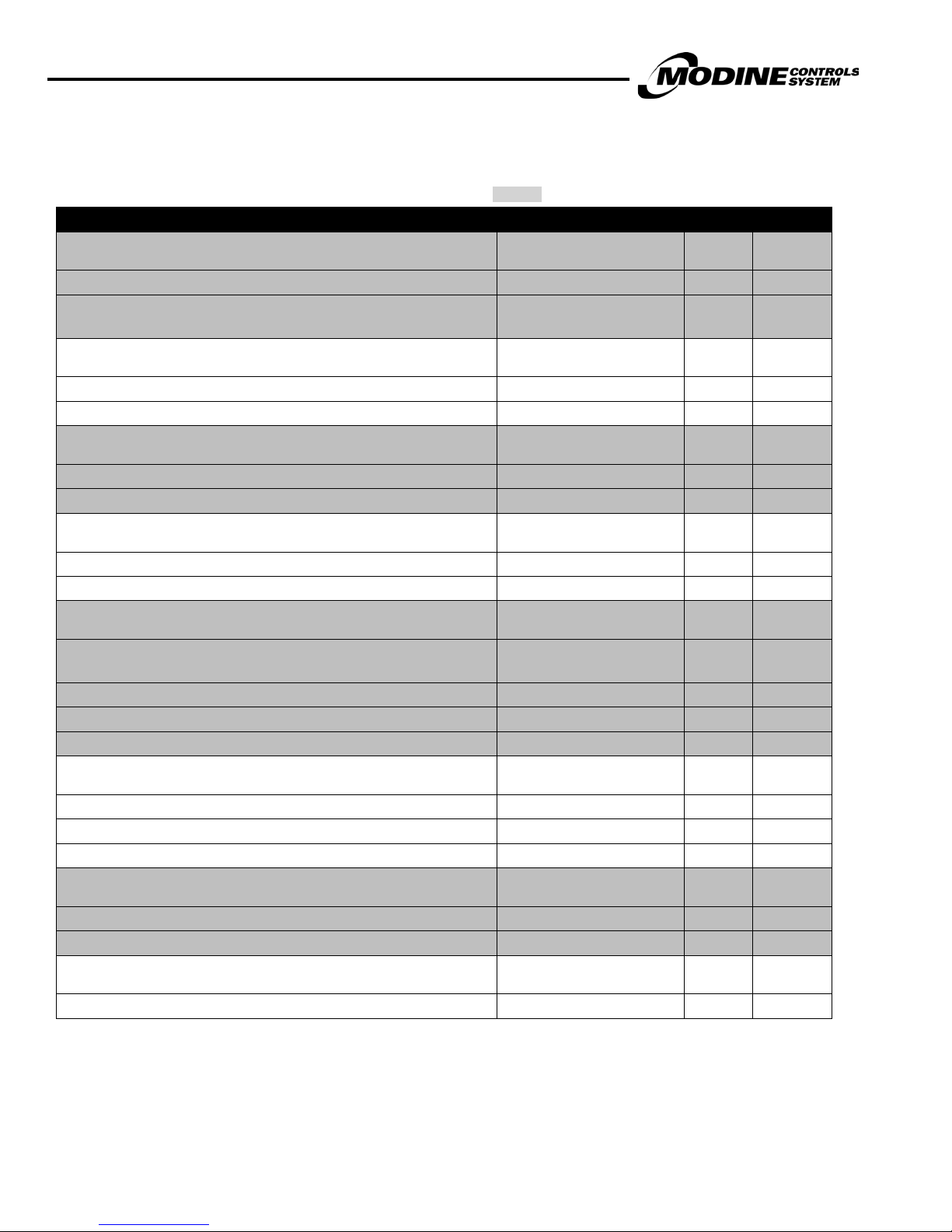
Main Status Screen Parameters (continued)
The status screens can be seen when the + buttons are pressed on the main status screen. The following table
describes the menu parameters (Note: Change in shading indicates change to next screen):
PARAMETER DESCRIPTION FACTORY VALUE RANGE UNITS
Note: The screen below will only be displayed if the unit
has an ERM module
ERM Wheel Actual Value On or Off
ERM Wheel Status (Optional) Actual Value Stopped or Running
Count On: Off:
Wheel minimum on and off counter
ERM By-Pass Damper Actual Value Open or Closed
ERM Pre-Heater On or Off
ERM Door Switch Open or Closed
Note: The screen below will only be displayed if the unit
has Gas or Electric Heat
Gas Or Electric Stages On Actual Value 0-2 (gas) 0-4 Elec. Heat
Heat Modulation Actual Value 0-100 %
Heating Lockout Warning Heating is locked out
Note: The screen below will only be displayed if the unit
is in EC3 Mode
Compressor 1 Status On or Off
Compressor 1 Minimum On Time Actual Value (Counts Down) 0-120 S
Compressor 1 Minimum Off Time Actual Value (Counts Up) 0-120 S
Compressor 2 Status On or Off
Compressor 2 Minimum On Time Actual Value (Counts Down) 0-120 S
Compressor 2 Minimum Off Time Actual Value (Counts Up) 0-120 S
Digital Compressor Modulation Actual Value 0-100 %
Note: The screen below will only be displayed if the unit
is in CDSS mode
Status (Digital Compressor)
Countdown Actual value S
Maximum Power Admitted Actual Value 0-100 %
Digital Compressor Actual Value On or Off
Valve Actual Value On or Off
Requested Capacity Actual Value 0-100 %
Current Capacity Actual Value 16.6-100 %
(continued on next page)
Actual Value Sec
Off
Start-up
On
Alarm
Off By Time
On By Time

MODINE CONTROL SYSTEM MANUAL
Models MPR & ERM
MCP15-525.0
17
No Enthalpy Lockout
Enthalpy LO Comp 1&2
Stand-By
I/O Automatic or
Reset Manual Controls
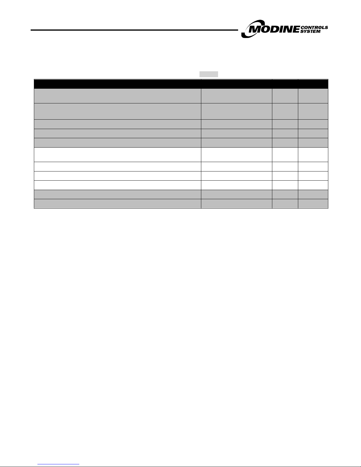
Main Status Screen Parameters (continued)
The status screens can be seen when the + buttons are pressed on the main status screen. The following table
describes the menu parameters (Note: Change in shading indicates change to next screen):
PARAMETER DESCRIPTION FACTORY VALUE RANGE UNITS
Note: The screen below will only be displayed if the unit
is in CDSS mode
Compressor 2 Status On or Off
Compressor 2 Minimum On Time Actual Value (Counts Down) 0-120 S
Compressor 2 Minimum Off Time Actual Value (Counts Up) 0-120 S
Note: The screen below will only be displayed if the unit
is in CDSS mode
Cooling Lockout
Compressor Enthalpy Lockout
Compressor Lockout
Condenser Fan Modulation Actual Value 0-100 %
Discharge Pressure Actual Value PSIG
Discharge Temperature (If in CDSS Mode) Actual value °F /°C
Suction Pressure Actual Value PSIG
Note: The screen below will only be displayed if the unit
is in CDSS mode
Liquid Line Temperature Actual value F /°C
Condensing Temperature Calculated F /°C
Sub-Cool Calculated F /°C
Capacity Reduction Actual Value 0-100 %
Note: The screen below will only be displayed if the unit
is in CDSS mode
Super-Heat Calculated F /°C
Suction Line Temperature Actual Value F /°C
Suction Pressure Actual Value PSIG
Evaporating Temperature Calculated F /°C
EEV Valve Steps Actual Value Depends On Valve Type Steps
EEV Value Percentage Actual Value 0-100 %
Valve Regulation
Enthalpy LO Comp 1
Enthalpy LO Comp 2
Compressor Held Off by
Lockout timers
Close
On
Position
Wait
Note: The next screen will only be displayed if a clock
schedule is enabled
Clock Override On or Off
Override Time 1-9 Hrs.
Manual Control Status & Reset Actual Value
I/O Manual

MODINE CONTROL SYSTEM MANUAL
Models MPR & ERM
18
MCP15-525.0
On/Off Sub Menu
Main Status Screen On/Off
The following table describes the menu parameters (Note: Change in shading indicates change to next s c reen):
PARAMETER DESCRIPTION FACTORY VALUE RANGE UNITS
Unit Address 1
Power By Display Actual Value On or Off
Unit On
OFF by Alarm
OFF by pLAN
OFF by BMS
OFF by Clock
Status Actual Value
Note: The screen below will only be displayed if the
optional Space wall stat is installed (pAD)
pAD Number Actual Value 1
On / Off Permanently Off - On or Off
OFF by Digital In
OFF by Keypad
OFF by Demand
OFF - Door Open
Off Manually
Wait - Damper
Wait Sup Fan
MODINE CONTROL SYSTEM MANUAL
Models MPR & ERM
MCP15-525.0
19
Setpoint Sub Menu
Main Status Screen Setpoint
The following table describes the menu parameters (Note: Change in shading indicates change to next s c reen):
PARAMETER DESCRIPTION FACTORY VALUE RANGE UNITS
Supply Air Setpoint 70 50-99 °F /°C
Current Setpoint Actual Value °F /°C
Note: The screen below will only be displayed if the optional Space wall
stat is installed (pAD)
pAD Thermostat Number Actual Value
Space Cooling Temperature Setpoint
Note: Heating Setpoint equals cooling setpoint minus 4°F
Space Humidity Setpoint 60 30-100 %RH
Space Humidity Differential 5 0-10 %
Unoccupied Cooling Setpoint 85 60-100 °F / °C
Unoccupied Heating Setpoint 62 40-100 °F / °C
Note: The screen below will only be displayed if Dew Point
Dehumidification is enabled
Occupied OA Dew point Setpoint 55 40-70 °F /°C
Occupied OA Dew point Differential 3 0-10 °F /°C
Unoccupied Space Dew point Setpoint 55 40-70 °F /°C
Unoccupied Space Dew point Differential 3 0-10 °F /°C
Note: The screen below will only be displayed if the optional space wall
stat is installed (pAD)
Occupied Space Humidity Setpoint 60 30-100 %RH
Occupied Space Humidity Differential 5 0-10 %
Unoccupied Space Humidity Setpoint 60 30-100 %RH
Unoccupied Space Humidity Differential 5 0-10 %
Note: The screens below will only be displayed if the unit is setup for
HOAS damper control
Outside Air Minimum Damper Position
Note: The Return Air Damper (Optional) will be the inverse of this value
OA Damper Position 1
Note: The Return Air Damper (Optional) will be the inverse of this value
OA Damper Position 2 50% ID15 Closed ID 16 Open 0-100 %
OA Damper Position 3 75% ID15 Open ID 16 Closed 0-100 %
OA Damper Position 4 100% ID15 and ID 16 Closed 0-100 %
Note: The Screen below will only be displayed if Damper CO2 Control is
selected
CO2 Setpoint 800 0-2000 PPM
CO2 Level Actual Value 0-2000 PPM
(continued on next page)
74 50-100 °F / °C
Setting depends on Unit type 0-100 %
30% ID15 and ID 16 Open 0-100 %
MODINE CONTROL SYSTEM MANUAL
Models MPR & ERM
20
MCP15-525.0
Setpoint Sub Menu (continued)
Main Status Screen Setpoint
The following table describes the menu parameters (Note: Change in shading indicates change to next s c reen):
PARAMETER DESCRIPTION FACTORY VALUE RANGE UNITS
Note: The Screen below will only be displayed if Damper Building
Pressure Control is selected
Building Pressure Setpoint 0.2 0-0.5 Inch W.G.
Building Pressure Actual Value 0-0.5
Note: The screen below will only be displayed if Supply Fan CO2 Control
is selected
CO2 Setpoint 800 0-2000 PPM
CO2 Level Actual Value 0-2000 PPM
Note: The Screen below will only be displayed if Supply Fan Building
Pressure Control is selected
Building Pressure Setpoint 0.2 0-0.5 Inch W.G.
Building Pressure Actual Value 0-0.5 Inch W.G.
Note: The screen below will only be displayed if Supply Fan Duct Static
Pressure Control is selected
Duct Static Pressure Setpoint 1.0 0-5 Inch W.G.
Duct Pressure Actual Value 0-5 Inch W.G.
Note: The Screen below will only be displayed if Supply Fan Constant
Volume Control is selected
Supply Fan Speed 1
Supply Fan Speed 2 85% ID15 Closed ID 16 Open 0-100 %
Supply Fan Speed 3 75% ID15 Open ID 16 Closed 0-100 %
Supply Fan Speed 4 50% ID15 and ID 16 Closed 0-100 %
Note: The screen below will only be displayed if Exhaust Fan Building
Pressure On/Off Control is selected
Building Pressure Setpoint 0.2 0-0.5 Inch W.G.
Building Pressure Differential 0.1 0-0.5 Inch W.G.
Building Pressure Actual Value 0-5 Inch W.G.
Note: The Screen below will only be displayed if Exhaust Fan Building
Pressure Control is selected
Building Pressure Setpoint 0.2 0-0.5 Inch W.G.
Building Pressure Actual Value 0-0.5 Inch W.G.
Note: The screen below will only be displayed if Exhaust Fan Offset
(from Supply Fan) Control is selected
Exhaust Fan Offset Setpoint (From Sup. Fan) 20 0-100 %
(continued on next page)
Inch W.G.
100% ID15 and ID 16 Open 0-100 %
MODINE CONTROL SYSTEM MANUAL
Models MPR & ERM
MCP15-525.0
21
Setpoint Sub Menu (continued)
Main Status Screen Setpoint
The following table describes the menu parameters (Note: Change in shading indicates change to next s c reen):
PARAMETER DESCRIPTION FACTORY VALUE RANGE UNITS
Note: The Screen below will only be displayed if Exhaust Fan Constant
Volume Control is selected
Exhaust Fan Speed 1
Exhaust Fan Speed 2 85% ID15 Closed ID 16 Open 0-100 %
Exhaust Fan Speed 3 75% ID15 Open ID 16 Closed 0-100 %
Exhaust Fan Speed 4 50% ID15 and ID 16 Closed 0-100 %
Note: The screen below will only be displayed if ERM Exhaust Fan
Building Pressure Control is selected
Building Pressure Setpoint 0.2 0-0.5 Inch W.G.
Building Pressure Actual Value 0-5 Inch W.G.
ERM Exhaust Fan Minimum Speed 50 0-100 %
Note: The Screen below will only be displayed if ERM is Enabled
ERM Exhaust Fan Minimum Speed 50 0-100 %
100% ID15 and ID 16 Open 0-100 %
MODINE CONTROL SYSTEM MANUAL
Models MPR & ERM
22
MCP15-525.0
Clock/Scheduler Sub Menu
Main Status Screen Clock/Scheduler
Note: The Schedule/Holidays can be used to either turn the unit On/Off or t o Cycle the unit from Occupied to Unoccupied (when
an Optional Space Sensor is installed).
The following table describes the menu parameters (Note: Change in shading indicates change to next screen):
PARAMETER DESCRIPTION FACTORY VALUE RANGE UNITS
Day Actual day Monday – Sunday -
Date Actual date MM/DD/YY -
Hour (Military Time) Actual time 00:00-23:59 -
Daylight Savings On On / Off
Transition Time 60 0-60 S
Start (Spring) Second Sunday in March @ 2:00am
End (Fall) First Sunday In November @ 3:00am
Number Of Schedules 0 0-7 -
Note: The screen below will only be shown if at least one
schedule is set
Schedule Number 1-7 Time On 00:00 00:00 – 23:59 Hrs:Min
Time Off 00:00 00:00 – 23:59 Hrs:Min
Days Enabled – Selects the days the schedule is to take effect. None MTWTFSS Days
Number of Holidays
Note: If a Holiday is one day the Start – Stop will be the same
e.g. 7/4 – 7/4
Holiday 1 Start - Stop 0 1/1/ - 12/31 Days
Holiday 2 Start - Stop 0 1/1/ - 12/31 Days
Holiday 3 Start - Stop 0 1/1/ - 12/31 Days
Holiday 4 Start - Stop 0 1/1/ - 12/31 Days
Holiday 5 Start - Stop 0 1/1/ - 12/31 Days
Holiday 6 Start - Stop 0 1/1/ - 12/31 Days
Holiday 7 Start - Stop 0 1/1/ - 12/31 Days
Holiday 8 Start - Stop 0 1/1/ - 12/31 Days
Holiday 9 Start - Stop 0 1/1/ - 12/31 Days
Holiday 10 Start - Stop 0 1/1/ - 12/31 Days
Holiday 11 Start - Stop 0 1/1/ - 12/31 Days
Holiday 12 Start - Stop 0 1/1/ - 12/31 Days
Holiday 13 Start - Stop 0 1/1/ - 12/31 Days
Holiday 14 Start - Stop 0 1/1/ - 12/31 Days
Holiday 15 Start - Stop 0 1/1/ - 12/31 Days
Holiday 16 Start - Stop 0 1/1/ - 12/31 Days
0 0-16 Days
MODINE CONTROL SYSTEM MANUAL
Models MPR & ERM
MCP15-525.0
23
Input / Output Sub Menu
Analog Inputs:
Main Status Screen Input/Output Analog Inputs
The following table describes the menu parameters (Note: Change in shading indicates change to next s c reen):
PARAMETER DESCRIPTION INPUT FACTORY VALUE RANGE UNITS
Return Air Humidity (Optional) B1 Actual 0-100 %RH
CO2 (Optional) B2 Actual 0-2000 PPM
Building Pressure (Optional) or
Duct Static Pressure
Outside Air Temperature B4 -999.9-999.9 °F / °C
Return Air Temperature (Optional) B5 Actual -999.9-999.9 °F / °C
Discharge Line Temperature (In CDSS Mode)
or Liquid Line Pressure (In EC3 Mode)
Outside Air Humidity B7 Actual 0-100 %RH
Not Used (In CDSS Mode) or Suction Pressure
(In EC3 Mode)
Mixed Air Temperature B9 Actual -999.9-999.9 °F / °C
Supply Air Temperature B10 Actual -999.9-999.9 °F / °C
Digital Inputs:
Main Status Screen Input/Output Digital Inputs
The following table describes the menu parameters (Note: Change in shading indicates change to next s c reen):
PARAMETER DESCRIPTION INPUT FACTORY VALUE RANGE UNITS
High Pressure ID1 Actual C/O Normally Closed
Low Pressure ID2 Actual C/O Normally Closed
Supply Fan Air Flow Switch ID3 Actual C/O Closed Fan On
Smoke Detector ID4 Actual C/O Normally Closed
Filter Dirty ID5 Actual C/O Normally Open
Damper End Switch ID6 Actual C/O Cls = Damp. Open
Occupied ID7 Actual C/O Cls = Occupied
Not Used In CDSS Mode or
Digital Compressor EC3 Alarm (In EC3 Mode)
Condensate Pan Float ID9 Actual C/O Normally Closed
Gas Valve 1 ID10 Actual C/O Cls = Valve Open
Gas Valve 2 ID11 Actual C/O Cls = Valve Open
Freeze Stat ID12 Actual C/O Not Used
Supply Fan Door Switch ID13 Actual C/O Cls = Door Closed
Remote On Off ID14 Actual C/O Cls = Unit On
Supply Fan Speed 2 or Damper Position 2 ID15 Actual C/O See Setpoints
Supply Fan Speed 3 or Damper Position 2 ID16 Actual C/O See Setpoints
Exhaust Fan Air Flow Switch ID17 Actual C/O Closed on Fan On
(continued on next page)
B3 Actual 0-4 “WG
B6 Actual
B8 Actual 0-500 PSIG
ID8 Actual C/O Normally Closed
-999.9-999.9
0-650
°F / °C
PSIG
MODINE CONTROL SYSTEM MANUAL
Models MPR & ERM
24
MCP15-525.0
Input / Output Sub Menu (continued)
Analog Outputs:
Main Status Screen Input/Output Analog Outputs
The following table describes the menu parameters (Note: Change in shading indicates change to next s c reen):
PARAMETER DESCRIPTION OUTPUT FACTORY VALUE RANGE UNITS
Not Used (In CDSS Mode) or Compressor
Modulation (EC3 Mode)
Digital Compressor Control Signal to the EC3
Module
Condenser Fan
Control Signal to the Condenser Fan VFD Drive
Note: The screen below will only be displayed
if Dehumidification Control is Enabled
Supplemental Electric Heat (In CDSS Mode) or
Hot Gas Re-Heat (EC3 Mode)
Control Signal to the Modulating Hot Gas Re-Heat
Interface Board (In EC3 Mode)
Heat
Control Signal to Either the Modulating Gas
Valves or the Electric Heat SCR controller
Supply Fan
Control Signal for the Supply Fan VFD (Optional)
Digital Relay Outputs:
Main Status Screen Input/Output Digital Outputs
The following table describes the menu parameters (Note: Change in shading indicates change to next screen):
PARAMETER DESCRIPTION OUTPUT FACTORY VALUE RANGE UNITS
Supply Fan DO7 Actual On/Off Condenser Fans DO8 Actual On/Off Compressor 1 DO3 Actual On/Off Compressor 2 DO4 Actual On/Off Outside Air Damper Open DO5 Actual On/Off Outside Air Damper Closed DO6 Actual On/Off Electric Heat 3 DO1 Actual On/Off Electric Heat 4 DO2 Actual On/Off Gas or Electric Heat 1 DO9 Actual On/Off Gas or Electric Heat 2 DO10 Actual On/Off Hot Gas Re-Heat Stage 2 DO11 Actual On/Off Gas Heat 1 Exhaust Fan High DO12 Actual On/Off Gas Heat 2 Exhaust Fan High DO13 Actual On/Off Digital Compressor Valve (In CDSS Mode) or
Hot Gas Re-Heat Close Off Valve (EC3 Mode)
General Alarm DO15 Actual On/Off -
Return Air Damper Open (Optional) DO16 Actual On/Off -
Return Air Damper Close (Optional) DO17 Actual On/Off -
Exhaust Fan (Optional) DO18 Actual On/Off -
AO1 Actual 0-10 Volts DC
AO2 Actual 0-10 Volts DC
AO3 Actual 0-10 Volts DC
AO4 Actual 0-10 Volts DC
AO5 Actual 0-10 Volts DC
DO14
Actual
Actual
On/Off
On/Off
-
MODINE CONTROL SYSTEM MANUAL
Models MPR & ERM
MCP15-525.0
25
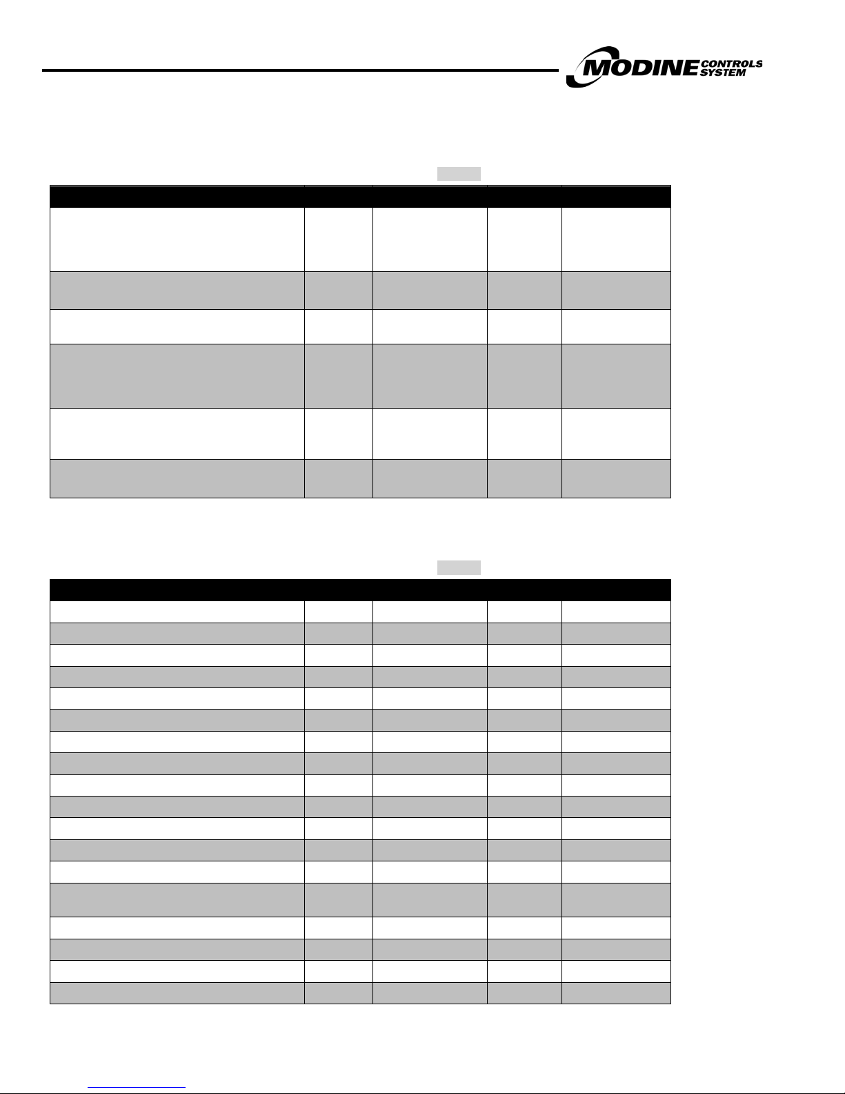
Data Logger Sub Menu
Main Status Screen Data Logger
To access contents of the Data Logger m enu simply press the button. The most recent alarm will be displayed on the screen.
The upper bar will display the time and date of the most recent alarm. The second line will indicate the alarm generated. The rest
of the page will contain readings of certain variables at the time of the alarm.
Use the button to navigate through previous alarms and the butt on to navigate to the most recent. The alarms are
chronologically stored and the most recent alarm will be the first di s pl ayed.
An example of an alarm log is shown bel ow:
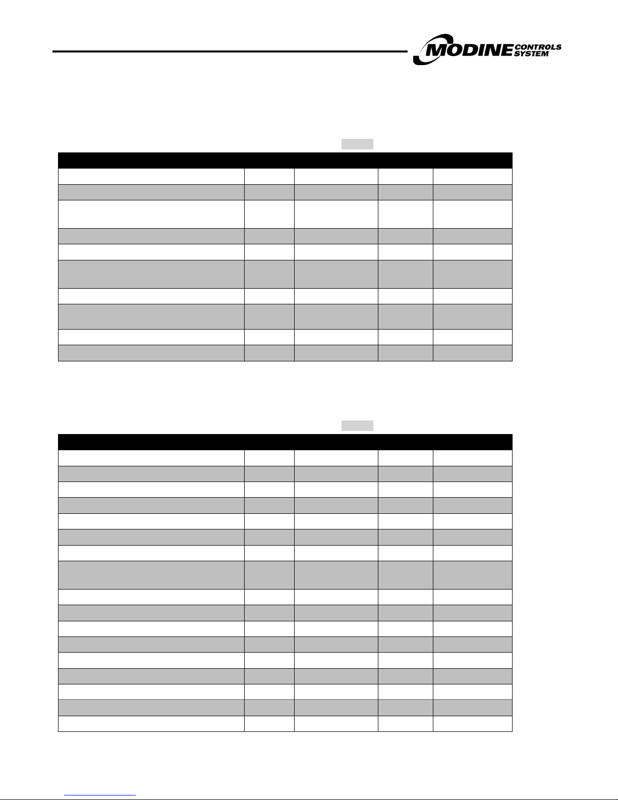
Board Switch Sub Menu
Main Status Screen Board Switch
The Board Switch screen will indic ate the current devices connected to the pLAN network (Keypad, pAD Wall S tat, and/or ERM
unit). In the screen below, the main controller is on address 1.
The pCO
In the situation that module addresses need to be set up, the board address c an be c hanged within the Board Switch sub menu.
3
controller is factory defaulted to th e following for modules communicat ed with on the pLAN:
3
• pCO
• ERM Module: Address 2
• Remote Wall Stat (pAD): Address 4
• Superheat Control (EVD only): Address 30
• Remote Display (pGD1): Address 32
Controller: Address 1
MODINE CONTROL SYSTEM MANUAL
Models MPR & ERM
26
MCP15-525.0
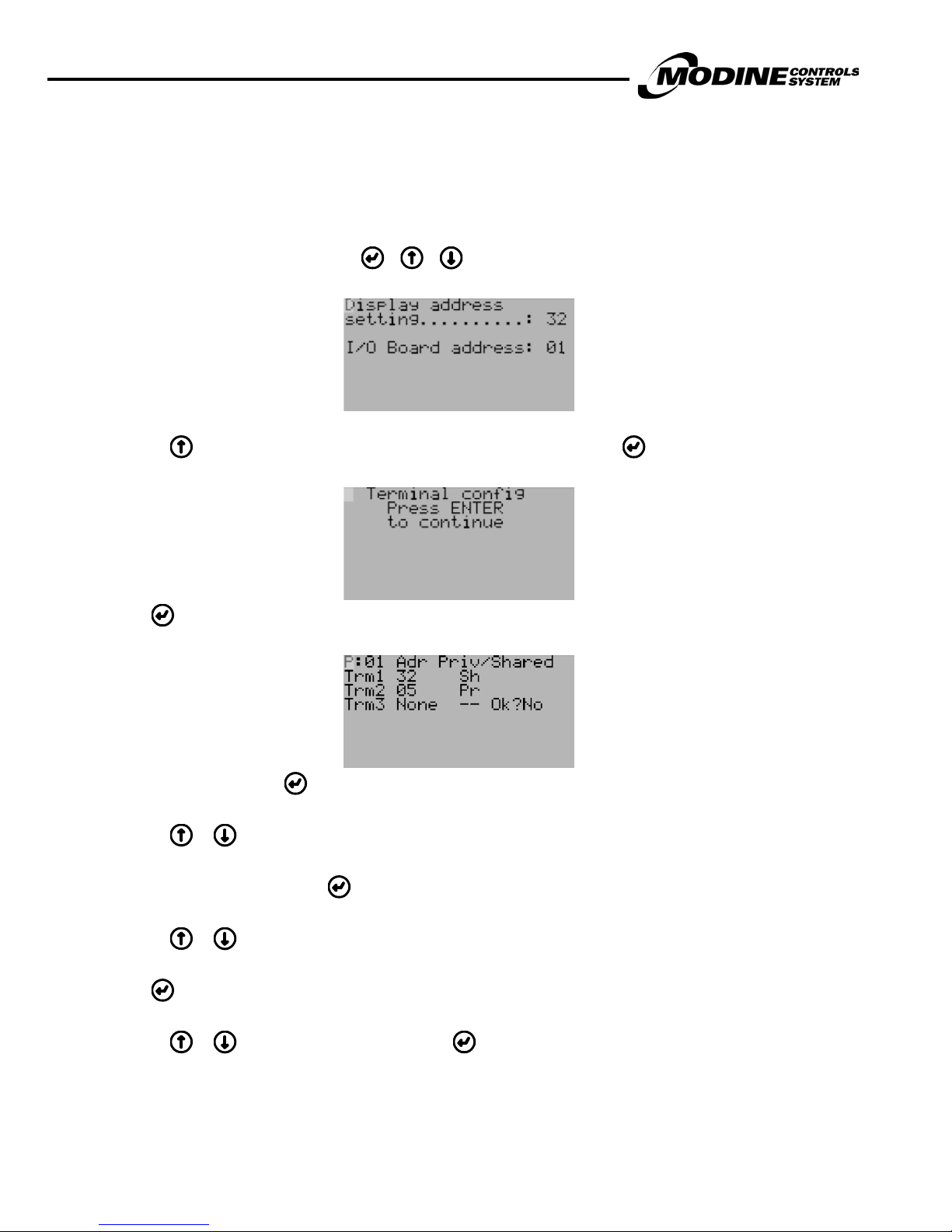
Programming the Remote Display Keypad to the Controller
In the situation that the terminal display address is required to be set up, t he following procedure applies:
1. Set the correct address on the display, connect to the controller and then power up the unit.
2. By simultaneously pressing a nd holding + + , the display will sh ow the Display Address screen.
3. Pressing will change the I/O board address to the controller address 1. Press to display the following screen:
4. Press again. The display will s how the following terminal configuration screen:
5. To select Terminal 1, press until the cursor is underneath Trm1 00 Pr.
6. Pressing or will change the 00 to the required value 32.
7. To set as Private or Shared, press until the cursor is underneath the Pr (PRIVATE) symbol.
8. Pressing or will change the Pr to Sh (SHARED) symbol. Pr For Normal – Sh if the unit has and ERM unit.
9. Press until the cursor is underneat h the NO.
10. Pressing or will change the NO to YE S. Press and the display is programmed.
MODINE CONTROL SYSTEM MANUAL
Models MPR & ERM
MCP15-525.0
27
PARA
Service Sub Menu
Information
Main Status Screen Service Information
The following table describes the menu parameters (Note: Change in shading indicates change to next screen):
METER DESCRIPTION FACTORY VALUE RANGE UNITS
Code (Name of Program) Actual Value - -
Software Version Actual Value - -
Bios Version Actual Value 0 – 99.99 -
Boot Version Actual Value 0 – 99.99 -
pCO Typ e pCO3 Large - -
Total flash Actual Value 0-9999 KB
RAM Actual Value 0-9999 KB
Built-In type Actual Value - -
T memory writes Actual Value - -
Main cycle Actual Value 0-9999 Cycle/s
Control Power Status - -
Last Off Time Actual Value
Last On Time Actual Value
Note: The screen below will only be displayed
if the unit is in CDSS mode
EVO Firmware Version Actual Value
(continued on next page)
MM/DD/YY –
HH:MM:SS
MM/DD/YY –
HH:MM:SS
MODINE CONTROL SYSTEM MANUAL
Models MPR & ERM
28
MCP15-525.0
Service Sub Menu (continued)
Working Hours
Main Status Screen Service Working Hours
The following table describes the menu parameters (Note: Change in shading indicates change to next s c reen):
PARAMETER DESCRIPTION FACTORY VALUE RANGE UNITS
Supply Fan Hours Actual Value 0-999,999 Hours
Supply Fan Number of Starts Actual Value 0-999,999 Compressor 1 Hours Actual Value 0-999,999 Hours
Compressor 1 Number of Starts - 0-999,999 Compressor 2 Hours Actual Value 0-999,999 Hours
Compressor 2 Number of Starts - 0-999,999 -
Note: The following three screens will only
be displayed if Gas Heat is enabled
Heat Exhaust Fan 1 Hours Actual Value 0-999,999 Hours
Heat Exhaust Fan 1 Number of Starts - 0-999,999 Heat Exhaust Fan 2 Hours Actual Value 0-999,999 Hours
Heat Exhaust Fan 2 Number of Starts - 0-999,999 Gas Heat 1 Hours Actual Value 0-999,999 Hours
Gas Heat 1 Number of Starts - 0-999,999 Gas Heat 2 Hours Actual Value 0-999,999 Hours
Gas Heat 2 Number of Starts - 0-999,999 -
Note: The following four screens will only
be displayed if Electric Heat is enabled
Electric Heat 1 Hours Actual Value 0-999,999 Hours
Electric Heat 1 Number of Starts - 0-999,999 Electric Heat 2 Hours Actual Value 0-999,999 Hours
Electric Heat 2 Number of Starts - 0-999,999 Electric Heat 3 Hours Actual Value 0-999,999 Hours
Electric Heat 3 Number of Starts - 0-999,999 Electric Heat 4 Hours Actual Value 0-999,999 Hours
Electric Heat 4 Number of Starts - 0-999,999 Exhaust Fan Hours Actual Value 0-999,999 Hours
Exhaust Fan Number of Starts - 0-999,999 -
Note: The following four screens will only
be displayed if the ERM Module is enabled
ERM Exhaust Fan Hours Actual Value 0-999,999 Hours
ERM Exhaust Fan Number of Starts - 0-999,999 ERM Wheel Hours Actual Value 0-999,999 Hours
ERM Wheel Number of Starts - 0-999,999 ERM Preheater Hours Actual Value 0-999,999 Hours
ERM Preheater Number of Starts - 0-999,999 -
(continued on next page)
MODINE CONTROL SYSTEM MANUAL
Models MPR & ERM
MCP15-525.0
29
PARAMETER DESCRIPTION
CAREL
9600
Service Sub Menu (continued)
BMS Configuration
Main Status Screen Service BMS Configuration ( requires password PW1)
The following table describes the menu parameters (Note: Change in shading indicates change to next screen):
FACTORY VALUE RANGE UNITS
NA
Lon
BACnet IP\Eth
Protocol
Note: The following three screens will only be displayed if
BACnet IP/Ethernet is selected and Enable Plugin is Yes.
The information set must be supplied by the controls
integrator.
Device Instance Actual Value 0-99,000 -
IP Address of the Device Actual Value 0.0.0.0 – 255.255.255.255 -
SubNet Actual Value 255.0.0.0 – 255.255.255.0 -
Gateway 0.0.0.0 – 255.255.255.255 DNS 1 Actual Value 0.0.0.0 – 255.255.255.255 -
DNS 2 Actual Value 0.0.0.0 – 255.255.255.255 -
Type IP
Function Read
Update No
Note: The following two screens will only be displayed if
BACnet MSTP is selected and Enable Plugin is Yes.
The information set must be supplied by the controls
integrator.
Device Instance Actual Value 0-99,000 -
BACnet MSTP
PCOLOAD
MODBUS
MODEM
The Modine Control System supports the
following Protocols:
Lon
BACnet IP/Eth
BACnet MSTP
IP
Ethernet
Read: Reads the settings from the card
Write: Write the setting to the card
Yes: Sends a Read or Write request to the
card (depending on the Function setting)
-
-
-
Baud Rate (of the MSTP Network) 38400
MAC Ad dres s (MSTP Station) 0 0-127
MaxMasters 0 0-127
MaxInfoFrames 0 1-99
Function Read
Update No
19200
38400
76800
Read: Reads the settings from the card
Write: Write the setting to the card
Yes: Sends a Read or Write request to the
card (depending on the Function setting)
bps
-
-
 Loading...