

Page 1
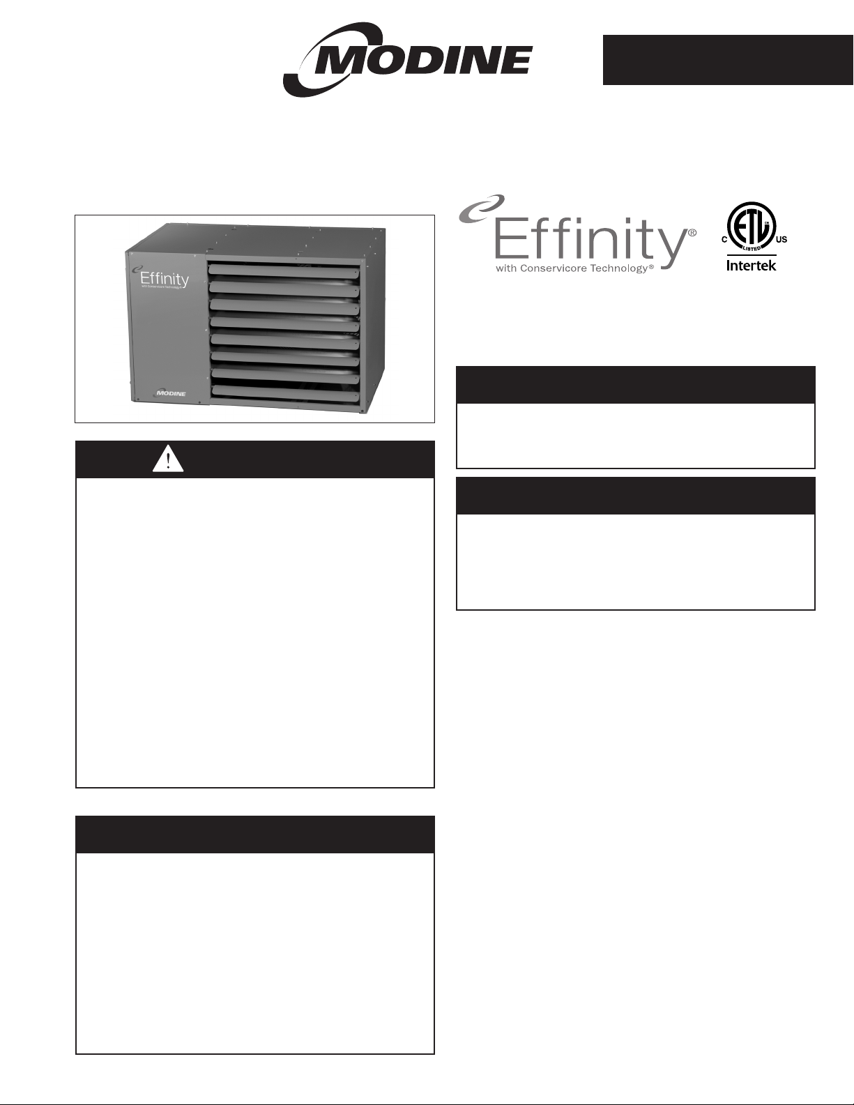
Model PTC
6-563.9
5H0807150000
November, 2018
INSTALLATION AND SERVICE MANUAL
high efficiency, separated combustion gas-fired unit heaters
models PTC and BTC
All models approved for use in California by the CEC and in
Massachusetts. Unit heater is certified for residential (size 110
and smaller only) and commercial applications.
®
Effinity, Conservicore Technology, and any combination of
these names either together or with other words is trademarked
by Modine Manufacturing Co.
FOR YOUR SAFETY
The use and storage of gasoline or other
flammable vapors and liquids in open containers
in the vicinity of this appliance is hazardous.
WARNING
1. Improper installation, adjustment, alteration,
service, or maintenance can cause property
damage, injury, or death and could cause
exposure to substances which have been
determined by various state agencies to
cause cancer, birth defects, or other
reproductive harm. Read the installation,
operating, and maintenance instructions
thoroughly before installing or servicing
this equipment.
2. Do not locate ANY gas-fired units in areas
where chlorinated, halogenated, or acidic
vapors are present in the atmosphere.
These substances can cause premature
heat exchanger failure due to corrosion,
which can cause property damage, serious
injury, or death.
FOR YOUR SAFETY
WHAT TO DO IF YOU SMELL GAS:
1. Open windows.
2. Do not try to light any appliance.
3. Do not touch any electrical switch; do
not use any phone in your building.
4. Extinguish any open flame.
5. Immediately call your gas supplier from a
neighbor’s phone. Follow the gas supplier’s
instructions. If you can not reach your gas
supplier, call your fire department.
THIS MANUAL IS THE PROPERTY OF THE OWNER.
PLEASE BE SURE TO LEAVE IT WITH THE OWNER WHEN YOU LEAVE THE JOB.
IMPORTANT
The use of this manual is specifically intended
for a qualified installation and service agency.
All installation and service of these units
must be performed by a qualified installation
and service agency.
Inspection on Arrival
1. Inspect unit upon arrival. In case of damage, report it
immediately to the transportation company and your local
Modine sales representative.
2.
Check rating plate on unit to verify that power supply meets
available electric power at the point of installation.
3. Inspect unit upon arrival for conformance with description of
product ordered (including specifications where applicable).
Table of Contents
Inspection on Arrival ................................. 1
Special Precautions ................................. 2
SI (Metric) Conversion Factors ........................ 3
Before You Begin . . . . . . . . . . . . . . . . . . . . . . . . . . . . . . . . . . . 3
Unit Location ...................................... 4
Combustible Material and Service Clearances .......... 4
Unit Mounting .................................... 5
Installation ........................................ 6
Venting . . . . . . . . . . . . . . . . . . . . . . . . . . . . . . . . . . . . . . . . . 6
Venting & Condensate Drain ....................... 13
Gas Connections ................................ 14
High-Altitude Accessory Kit ........................ 15
Electrical Connections ............................ 17
Ductwork....................................... 18
Performance Data ................................. 20
Dimensions....................................... 26
Service/Troubleshooting............................. 28
Model/Serial Number/Replacement Parts ............... 31
Commercial Warranty........................Back Cover
Page 2
SPECIAL PRECAUTIONS
SPECIAL PRECAUTIONS
THE INSTALLATION AND MAINTENANCE INSTRUCTIONS IN
THIS MANUAL MUST BE FOLLOWED TO PROVIDE SAFE,
EFFICIENT AND TROUBLE-FREE OPERATION. IN ADDITION,
PARTICULAR CARE MUST BE EXERCISED REGARDING THE
SPECIAL PRECAUTIONS LISTED BELOW. FAILURE TO
PROPERLY ADDRESS THESE CRITICAL AREAS COULD
RESULT IN PROPERTY DAMAGE OR LOSS, PERSONAL
INJURY, OR DEATH. THESE INSTRUCTIONS SUBJECT TO
ANY MORE RESTRICTIVE LOCAL OR NATIONAL CODES.
HAZARD INTENSITY LEVELS
1. DANGER: Indicates an imminently hazardous situation
which, if not avoided, WILL result in death or serious injury.
2. WARNING: Indicates a potentially hazardous situation
which, if not avoided, COULD result in death or serious injury.
3. CAUTION: Indicates a potentially hazardous situation which,
if not avoided, MAY result in minor or moderate injury.
4. IMPORTANT: Indicates a situation which, if not avoided,
MAY result in a potential safety concern.
DANGER
Appliances must not be installed where they may be exposed
to a potentially explosive or flammable atmosphere.
WARNING
1. Gas fired heating equipment must be vented - do not
operate unvented.
2. A built-in power exhauster is provided - additional external
power exhausters are not required or permitted.
3. Unit must not be common vented with other appliances.
4. If an existing heater is being replaced, the vent system
must meet the requirements specified in this manual.
Improperly sized or constructed venting systems can
result in vent gas leakage or the formation of condensate.
Failure to follow these instructions can result in injury
or death.
5. In locations where the outside air temperature falls below
freezing, icicles may form on horizontal vent terminations
from the condensate formed in the vent system. Locate the
vent termination where a falling icicle will not be a hazard.
6. Installation must conform with local building codes or in
the absence of local codes, the National Fuel Gas Code,
ANSI Z223.1 (NFPA 54) - latest edition. In Canada
installation must be in accordance with CSA-B149.1.
7. Do not install PVC pipe near high temperature sources of
heat exceeding 140°F that could damage the pipe and
cause hazardous leaks of products of combustion or
water into the space.
8. All field gas piping must be pressure/leak tested prior to
operation. Never use an open flame. Use a soap solution
or equivalent for testing.
9. Gas pressure to appliance controls must never exceed
14" W.C. (1/2 psi).
10. To reduce the opportunity for condensation, the minimum
sea level input to the appliance, as indicated on the serial
plate, must not be less than 5% below the rated input, or
5% below the minimum rated input of dual rated units.
11. Disconnect power supply before making wiring
connections to prevent electrical shock and equipment
damage.
12. All appliances must be wired strictly in accordance with
the wiring diagram furnished with the appliance. Any
wiring different from the wiring diagram could result in a
hazard to persons and property.
WARNING
13. Any original factory wiring that requires replacement must
be replaced with wiring material having a temperature
rating of at least 105°C.
14. Ensure that the supply voltage to the appliance, as
indicated on the serial plate, is not 5% greater than or 5%
less than the rated voltage.
15. When servicing or repairing this equipment, use only
factory-approved service replacement parts. A complete
replacements parts list may be obtained by contacting
the factory. Refer to the rating plate on the appliance for
complete appliance model number, serial number, and
company address. Any substitution of parts or controls not
approved by the factory will be at the owner's risk.
CAUTION
1. All literature shipped with this unit should be kept for
future use for servicing or service diagnostics. Do not
discard any literature shipped with this unit.
2. Consult piping, electrical, and venting instructions in this
manual before final installation.
3. Do not attach ductwork, air filters, or polytubes to any
propeller unit heater.
4. Clearances to combustible materials are critical. Be sure
to follow all listed requirements.
5. Heaters are designed for use in heating applications with
ambient temperatures between 40°F and 80°F. Heaters
should not be used in applications where the heated
space temperature is below 40°F. The combination of low
space and combustion air temperatures may result in
condensate freezing in the secondary heat exchanger
and/or condensate drain.
6. Do not install unit outdoors.
7. In garages or other sections of aircraft hangars such as
offices and shops that communicate with areas used for
servicing or storage, keep the bottom of the unit at least
7' above the floor unless the unit is properly guarded to
provide user protection from moving parts and interior
surface temperatures that can cause serious burns if
touched. In parking garages, the unit must be installed in
accordance with the standard for parking structures ANSI/
NFPA 88A, and in repair garages the standard for repair
garages NFPA 30A (formerly NFPA 88B). In Canada,
installation of heaters in airplane hangars must be in
accordance with the requirements of the enforcing
authority, and in public garages in accordance with the
current CSA-B149 codes.
8. In aircraft hangars, keep the bottom of the unit at least 10'
from the highest surface of the wings or engine enclosure
of the highest aircraft housed in the hangars and in
accordance with the requirements of the enforcing
authority and/or NFPA 409 - latest edition.
9. Installation of units in high humidity or salt water
atmospheres will cause accelerated corrosion resulting in
a reduction of the normal life of the units.
10. Do not install units below 7' measured from the bottom of
the unit to the floor in commercial applications (unless unit
is properly guarded to provide user protection from
moving parts and interior surface temperatures that can
cause serious burns if touched) and 5' measured from the
bottom of the unit to the floor in residential applications
(sizes 110 and smaller only).
11. Be sure no obstructions block air intake and discharge of
unit heaters.
2
6-563.9
Page 3
SPECIAL PRECAUTIONS / SI (METRIC) CONVERSION FACTORS
BEFORE YOU BEGIN
CAUTION
12. The minimum distance from combustible material is based
on the combustible material surface not exceeding 160°F.
Clearance from the top of the unit may be required to be
greater then the minimum specified if heat damage, other
than fire, may occur to materials above the unit heater at
the temperature described.
13. Allow 18" of clearance at rear (or 12" beyond end of
motor at rear of unit, whichever is greater) and access
side to provide ample air for proper operation of fan.
14. The concentric vent adapter box must be installed inside
of the structure or building. Do not install this box on the
exterior of a building or structure.
15. Purging of air from gas supply line should be performed
as described in the National Fuel Gas Code, ANSI Z223.1
(NFPA 54) - latest edition, or in Canada in CSA-B149
codes.
16. When leak testing the gas supply piping system, the
appliance and its combination gas control must be
isolated during any pressure testing in excess of 14" W.C.
(1/2 psi).
17. The unit should be isolated from the gas supply piping
system by closing its field installed manual shut-off valve.
This manual shut-off valve should be located within 6' of
the heater.
18. Turn off all gas before installing appliance.
19. Check the gas inlet pressure at the unit upstream of the
combination gas control. The inlet pressure should be
6-7" W.C. on natural gas or 12-14" W.C. on propane. If
inlet pressure is too high, install an additional pressure
regulator upstream of the combination gas control.
20. Service or repair of this equipment must be performed by
a qualified service agency.
21. Do not attempt to reuse any mechanical or electronic
ignition controller which has been wet. Replace defective
controller.
IMPORTANT
1. To prevent premature heat exchanger failure, do not locate
ANY gas-fired appliances in areas where corrosive vapors
(i.e. chlorinated, halogenated, or acidic) are present in the
atmosphere.
2. To prevent premature heat exchanger failure, the input to
the appliance as indicated on the serial plate, must not
exceed the rated input by more than 5%. Verify that the
blower has been set to the proper RPM for the
application. Refer to page 19 for blower adjustments.
3. Start-up and adjustment procedures must be performed
by a qualified service agency.
1. All literature shipped with this unit should be kept for future
use for servicing or service diagnostics. Leave manual with
the owner. Do not discard any literature shipped with this unit.
2. Consult piping, electrical, and venting instructions in this
manual before final installation.
3. Do not attach ductwork, air filters, or polytubes to any
propeller unit heater.
In the U.S., the installation of these units must comply with the
the National Fuel Gas Code, ANSI Z223.1 (NFPA 54) - latest
edition, or in other applicable local building codes. In Canada,
the installation of these units must comply with local plumbing
or waste water codes and other applicable codes and with the
current code CSA-B149.1.
1. All installation and service of these units must be
performed by a qualified installation and service agency
only as defined in ANSI Z223.1 (NFPA 54) - latest edition or
in Canada by a licensed gas fitter.
2. This unit is certified with the controls furnished. For
replacements parts, please order according to the
replacement parts list on serial plate. Always know your
model and serial numbers. Modine reserves the right to
substitute other authorized controls as replacements.
3. Unit is balanced for correct performance. Do not alter fan
or operate motors at speeds below what is shown in this
manual.
4. Information on controls is supplied separately.
SI (Metric) Conversion Factors
To Convert Multiply By To Obtain
°F (°F-32) x 5/9 °C
BTU 1.06 kJ
Btu/ft3 37.3 kJ/m
Btu/hr 0.000293 kW
CFH (ft3/hr) 0.000472 m3/min
CFH (ft3/hr) 0.00000787 m3/s
CFM (ft3/min) 0.0283 m3/min
CFM (ft3/min) 0.000472 m3/s
feet 0.305 m
Gal/Hr. 0.00379 m3/hr
Gal/Hr. 3.79 l/hr
gallons 3.79 l
Horsepower 746 W
inches 25.4 mm
pound 0.454 kg
psig 6.89 kPa
psig 27.7 "W.C.
"W.C. 0.249 kPa
CAUTION
3
6-563.9
3
Page 4
UNIT LOCATION
UNIT LOCATION
DANGER
Appliances must not be installed where they may be
exposed to a potentially explosive or flammable atmosphere.
CAUTION
1. Clearances to combustible materials are critical. Be sure to
follow all listed requirements.
2. Heaters are designed for use in heating applications with
ambient temperatures between 40°F and 80°F. Heaters
should not be used in applications where the heated space
temperature is below 40°F. The combination of low space
and combustion air temperatures may result in condensate
freezing in the secondary heat exchanger and/or
condensate drain.
3. Do not install unit outdoors.
4. In garages or other sections of aircraft hangars such as
offices and shops that communicate with areas used for
servicing or storage, keep the bottom of the unit at least
7’ above the floor unless the unit is properly guarded to
provide user protection from moving parts and interior
surface temperatures that can cause serious burns if
touched. In parking garages, the unit must be installed in
accordance with the standard for parking structures ANSI/
NFPA 88A, and in repair garages the standard for repair
garages NFPA 30A (formerly NFPA 88B). In Canada,
installation of heaters in airplane hangars must be in
accordance with the requirements of the enforcing
authority, and in public garages in accordance with the
current CSA-B149 codes.
5. In aircraft hangars, keep the bottom of the unit at least
10' from the highest surface of the wings or engine
enclosure of the highest aircraft housed in the hangars
and in accordance with the requirements of the enforcing
authority and/or NFPA 409 - latest edition.
6. Installation of units in high humidity or salt water
atmospheres will cause accelerated corrosion resulting in
a reduction of the normal life of the units.
IMPORTANT
To prevent premature heat exchanger failure, do not locate
ANY gas-fired appliances in areas where corrosive vapors
(i.e. chlorinated, halogenated, or acidic) are present in the
atmosphere.
Location Recommendations
1. When locating the heater, consider general space and
heating requirements, availability of gas and electrical supply,
and proximity to vent locations and condensate drain lines.
2. When locating units, it is important to consider that the
combustion air and exhaust vent piping must be connected
to the outside atmosphere. Vent terminals should be located
adjacent to one another. Maximum equivalent vent lengths
are listed in “Section A - General Instruction - All Units” of the
Venting instructions.
3. Be sure the structural support at the unit location site is
adequate to support the unit's weight. Refer to pages 26 and
27 for unit weights. For proper operation the unit must be
installed in a level horizontal position.
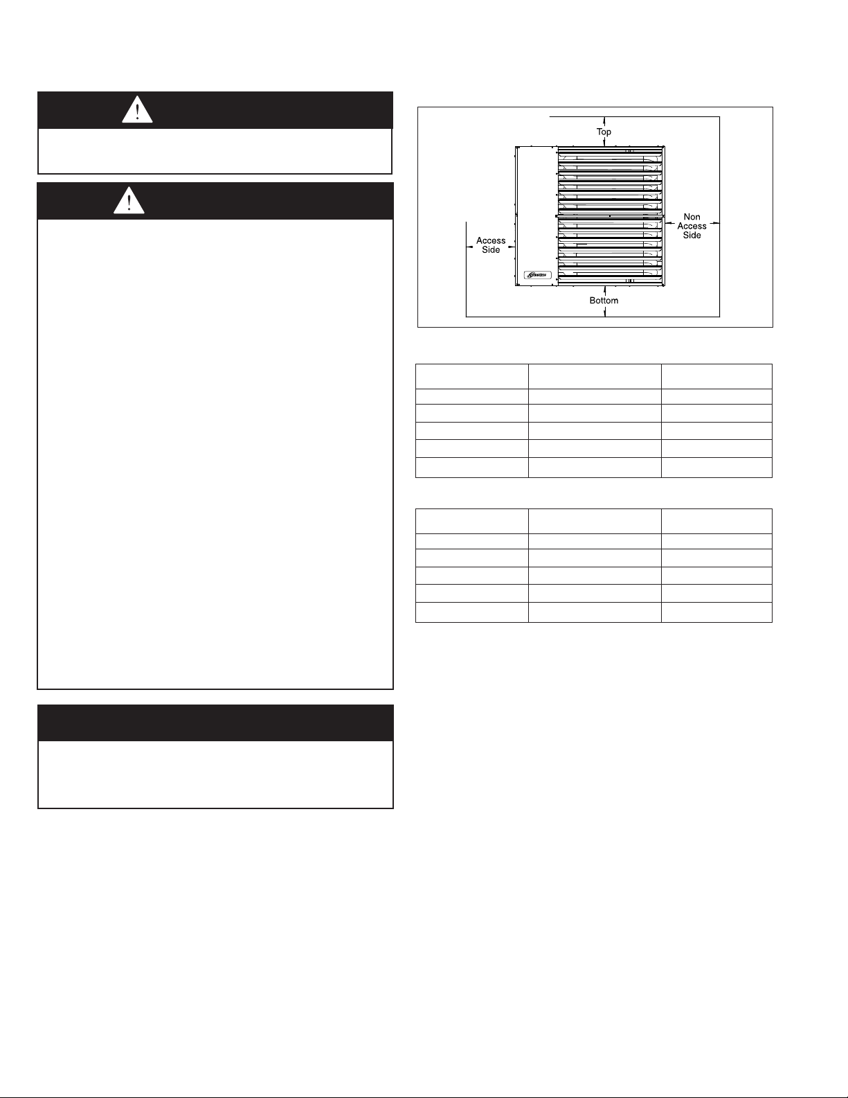
Figure 4.1 - Combustible Material and Service
Clearances
Table 4.1 - Clearances - Sizes 110 and Below
Unit Side
Combustible Materials Service Clearance
Top and Bottom 1" 18"
Access Side 1" 18"
Non-Access Side 1" 18"
Rear 18" 18"
Vent Connector 6" 18"
Clearance To Recommended
Table 4.2 - Clearances - Sizes 135-310
Unit Side
Combustible Materials Service Clearance
Top and Bottom 6" 18"
Access Side 6" 18"
Non-Access Side 6" 18"
Rear 18" 18"
Vent Connector 6" 18"
4. Do not install units in locations where the flue products
can be drawn into the adjacent building openings such as
windows, fresh air intakes, etc.
5. Be sure that the minimum clearances to combustible
materials and recommended service clearances are
maintained. Units are designed for installation with the
minimum clearances as shown in Figure 4.1 and Table 4.1.
Clearance from the top of the unit may be required to be
greater than 6" if heat damage other than fire could result
(such as material distortion or discoloration).
6. Do not install units in locations exposed to water spray, rain,
or dripping water.
7. Mounting height (measured from bottom of unit) at which unit
heaters are installed is critical. Refer to mounting height and
heat throw data on page 24 of this manual. The maximum
mounting height for any unit is that height above which the
unit will not deliver heated air to the floor.
Clearance To Recommended
Sound and Vibration Levels
All standard mechanical equipment generates some sound and
vibration that may require attenuation. Libraries, private offices
and hospital facilities will require more attenuation, and in such
cases, an acoustical consultant may be retained to assist in the
application. Locating the equipment away from the critical area
is desirable within ducting limitations. Generally, a unit should
be located within 15' of a primary support beam. Smaller
deflections typically result in reduced vibration and noise
transmission.
4
6-563.9
Page 5
UNIT MOUNTING
CAUTION
1. Do not install units below 7' measured from the bottom of
the unit to the floor in commercial applications (unless
unit is properly guarded to provide user protection from
moving parts and interior surface temperatures that can
cause serious burns if touched) and 5' measured from the
bottom of the unit to the floor in residential applications
(sizes 110 and smaller only).
2. Be sure no obstructions block air intake and discharge
of unit heaters.
3. The minimum distance from combustible material is
based on the combustible material surface not exceeding
160°F. Clearance from the top of the unit may be required
to be greater than the minimum specified if heat damage,
other than fire, may occur to materials above the unit
heater at the temperature described.
4. Allow 18" clearance at rear (or 12" beyond end of motor
at rear of unit, whichever is greater) and access side to
provide ample air for proper operation of fan.
1. Be sure the means of suspension is adequate to support
the weight of the unit (see pages 26 and 27 for unit weights).
2. For proper operation, the unit must be installed in a level
horizontal position from front to back and side to side.
3. Clearances to combustibles as specified in Table 4.1 must be
strictly maintained.
4. All standard units are shipped fully boxed. Larger units are
also supplied with skid supports on the bottom of the box.
The larger units may be lifted from the bottom by means of a
fork lift or other lifting device only if the shipping support skids
are left in place and the forks support the whole depth of the
unit. If the unit must be lifted from the bottom for final
installation without the carton in place, be sure to properly
support the unit over its entire length and width to prevent
damage. When lifting units, make sure the load is balanced.
5. Propeller models have four mounting holes and blower
models have six mounting holes. The units can be mounted
with 3/8"-16 threaded rod as follows:
•Oneachpieceofthreadedrodused,screwanutadistance
of about 1" onto the end of the threaded rods that will be
screwed into the unit heater.
•Placeawasherovertheendofthethreadedrodandscrew
the threaded rod into the unit heater weld nuts on the top of
the heater at least 5 turns, and no more than 10 turns.
Tighten the nut first installed onto the threaded rod to
prevent the rod from turning.
•Drillholesintoasteelchannelorangleironatthesame
center-line dimensions as the heater that is being installed.
The steel channels or angle iron pieces need to span and
be fastened to appropriate structural members.
•Cutthethreadedrodstothepreferredlength,placethem
through the holes in the steel channel or angle iron and
secure with washers and lock nuts or lock washers and
nuts. A double nut arrangement can be used here instead of
at the unit heater (a double nut can be used both places but
is not required).
•Donotinstallstandardunitheatersabovethemaximum
mounting height shown in Tables 24.1 or 24.2.
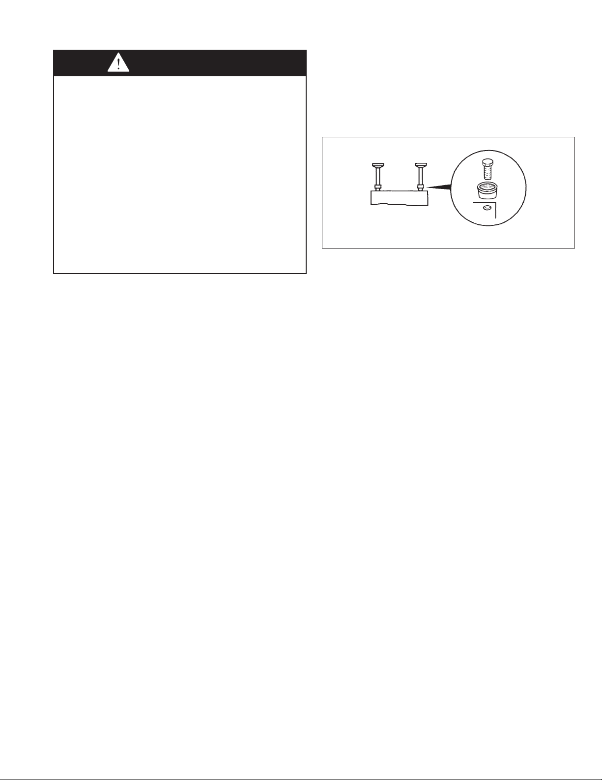
Alternate Suspension Methods
A pipe hanger adapter kit, shown in Figure 5.1, is available as
an accessory. One kit consists of two drilled 3/4" IPS pipe caps
and two 3/8"-16 x 1-1/2" capscrews to facilitate threaded pipe
suspension. Two kits would be required for PTC units and 3 kits
for BTC units.
Figure 5.1 - Unit Heater Suspension Methods
Pipe Adaptor Kit
Also available is a 2-point mounting kit for installations where
the ceiling structure only allows for 2 mounting points. Refer to
the latest revision of literature #6-574 for instructions.
6-563.9
5
Page 6
INSTALLATION - VENTING
WARNING
1. Gas fired heating equipment must be vented - do not
operate unvented.
2. A built-in power exhauster is provided - additional external
power exhausters are not required or permitted.
3. Unit must not be common vented with other appliances.
4. If an existing heater is being replaced, the vent system
must meet the requirements specified in this manual.
Improperly sized or constructed venting systems can result
in vent gas leakage or the formation of condensate. Failure
to follow these instructions can result in injury or death.
5. In locations where the outside air temperature falls below
freezing, icicles may form on horizontal vent terminations
from the condensate formed in the vent system. Locate the
vent termination where a falling icicle will not be a hazard.
6. Do not install PVC pipe near high temperature sources of
heat exceeding 140°F that could damage the pipe and
cause hazardous leaks of products of combustion or water
into the space.
CAUTION
Installation must conform with local building codes or in the
absence of local codes, with the National Fuel Gas Code,
ANSI Z223.1 (NFPA 54) - latest edition. In Canada installation
must be in accordance with CSA B149.1.
Model PTC and BTC unit heaters must be vented with the
proper passageway as described in these instructions to
convey flue gases from the unit or the vent connector to the
outside atmosphere. The heaters must also have a separate
combustion air intake pipe to bring in fresh air for combustion
from the outside atmosphere.
The venting instructions are organized in sections, based on
installation type. The sections are identified as follows:
Instructions Applicable Installation Instructions
Section by Vent System Type
A General Instructions for ALL installations
B VERTICAL vent systems j
C HORIZONTAL vent systems j
VERTICAL CONCENTRIC vent systems k
jThe differences between vertical and horizontal vent systems in 2-Pipe or
k
Section A - General Instructions - All Units
A1. If the unit heater being installed is replacing existing
Additional requirements for HORIZONTAL AND
D
concentricventcongurationswillbeidentiedin“SectionA-General
Instructions – All Units”.
For 2-Pipe installations, only sections B or C are required. For a concentric
vent installation, section B or C must be followed, along with additional
instructions shown in section D.
equipment and using the existing vent system from that
equipment, inspect the venting system for proper materials,
size and horizontal pitch, as required in these instructions.
Determine that there is no blockage or restriction, leakage,
corrosion and other deficiencies, which could cause an
unsafe condition.
A2. Model PTC/BTC units feature high thermal efficiency and
are certified as Category IV vented appliances. The units
will produce condensate during operation. Both the heater
and the vent system must be connected to a condensate
removal drain, which is detailed in this manual.
A3. Vent pipe must be Schedule 40 PVC pipe. In Canada,
all PVC vent pipe must be approved to ULC S636. The
combustion air inlet pipe must be Schedule 40 PVC for
model sizes 260 and smaller. For model size 310, the
combustion air inlet pipe must be sealed, single wall
galvanized steel or other suitable corrosion resistant
material.
A4. All heaters come with factory installed vent and combustion
air adapters for attaching the vent and combustion air inlet
piping to the heater (refer to Table 6.1 for applicable
connector sizes).
Table 6.1 - Combustion Air & Vent Pipe Connection
Model Size
55-135
156-260 4" PVC/Poly 4" PVC/Poly
310 6" Steel/Poly 4" PVC/Poly
➀ Size 110 and smaller maximum vent length is 25'.
A5. Attach the vent pipe to the unit heater vent connection
adapter by sliding the pipe into the rubber exhaust pipe
coupling located on the back of the unit. Tighten the pipe
clamp to secure the vent pipe to the unit. Vent pipe must
not be smaller than the connector size.
A6. Attach the combustion air inlet pipe to the unit heater inlet
air connection adapter with 3 corrosion resistant screws.
(Drill pilot holes through the pipe and adapter prior to
screwing in place). Pipe must not be smaller than the
connector size.
A7. Limit the total equivalent vent pipe length to a minimum of
5' and a maximum of 50' (25' for sizes 110 and smaller),
making the vent system as straight as possible. The
equivalent length of a 3" or 4" 90° elbow is 6' and for a 6"
90° elbow is 7'. Two 45° elbows are equivalent to one 90°
elbow. The combustion air inlet pipe length should be
approximately the same as the vent pipe.
A8. A minimum of 12" straight pipe is recommended from the
flue outlet before turns in the vent pipe.
A9. The vent and combustion air piping must be properly
supported with special consideration to the weight of the
piping system. The approximate weight per 10' sections of
Schedule 40 PVC is 14 lbs. for 3" diameter, 20 lbs. for 4"
diameter, and 35 lbs. for 6" diameter. Do not use the
heater or concentric adapter box to provide support.
A10. Horizontal sections of vent pipe are to be installed with a
minimum upward pitch from the appliance of 1/4" per foot
and suspended securely from overhead structures at
points not greater than 3' apart. Cradle type hangers
should be used to allow for expansion and contraction.
A11. To ensure the piping is leak free after installation, the
Schedule 40 PVC vent system, and combustion air inlet
piping on applicable model sizes, must be solvent welded
(glued) in a manner consistent with normal industry
standards and in compliance with all local fire and building
code requirements. Primer for joints should conform to
ASTM F 656. Cement for joints should conform to
ASTM D 2564. For single wall metal combustion air inlet
piping (model size 310 only), see note A12 for proper joint
sealing.
Combustion Air Inlet Flue Exhaust Outlet
Diameter Material Diameter Material
3" PVC/Poly 3" PVC/Poly
6
6-563.9
Page 7
INSTALLATION - VENTING
A12. For single wall galvanized combustion air inlet piping
(model size 310 only), seal joints and seams with silicone
sealant or 2 turns of metallic tape. Fasten individual
lengths of vent together with at least 3 corrosion resistant
sheet metal screws.
A13. Do not install PVC pipe near high temperature sources of
heat exceeding 140°F that could damage the pipe and
cause hazardous leaks of products of combustion or water
into the space.
A14. Avoid venting through unheated space when possible.
A15. When the vent passes through a combustible wall or roof,
no special clearance to combustible precautions are
required to the materials through which the vent passes.
Because of the low flue gas temperature, the vent is
certified as zero clearance.
A16. Minimum vent termination clearances must be maintained
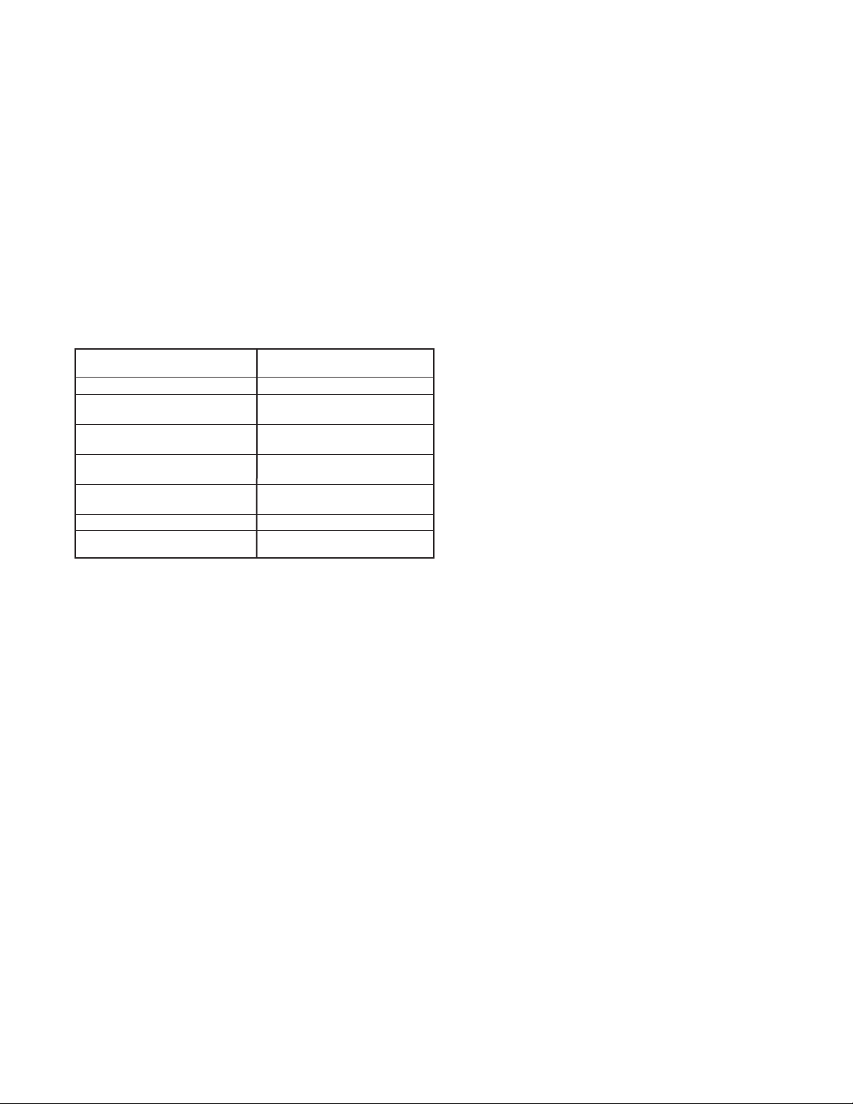
per Table 7.1:
Table 7.1 - Minimum Vent Termination Clearances
Minimum Clearances for
Forced air inlet within 10 feet 3 feet above
Combustion air inlet of another
appliance 6 feet all directions
Door, window, gravity air inlet, 4 feet horizontal and below
or any building opening 1 foot above
Electric meter, gas meter, and 4 feet horizontal (U.S.)
relief equipment ➀ 6 feet horizontal (Canada)
Gas regulator ➀
6 feet horizontal (Canada)
Adjacent public walkways 7 feet all directions
Grade (ground level) 3 feet above ➁
➀ Do not terminate the vent directly above a gas meter or regulator.
➁ The vent must be at least 12" higher than anticipated snow depth.
A17. Do NOT vent this appliance into a masonry chimney.
A18. Do NOT use dampers or other devices in the vent or
A19.
A20. Precautions must be taken to prevent degradation of
A21. To improve the ability to inspect and maintain the vent
A22. Long runs of horizontal or vertical combustion air pipes
A23. Vertical combustion air pipes should be fitted with a tee
A24. In addition to following these General Instructions, specific
Structure
Vent Terminal Location
3 feet horizontal (U.S.)
combustion air pipes.
The venting system must be exclusive to a single
appliance, and no other appliance is allowed to be vented
into it.
building materials by flue products.
system, it is recommended that the vent pipe not pass
through any unoccupied attic, inside wall, concealed
space, or floor.
may require insulation in very cold climates to prevent the
buildup of condensation on the outside of the pipe where
the pipe passes through conditioned spaces.
with a drip leg and a clean out cap to prevent against the
possibility of any moisture in the combustion air pipe from
entering the unit. The drip leg should be inspected and
cleaned out periodically during the heating season.
instructions for Vertical and Horizontal vent systems in
2-Pipe or Concentric Vent configurations must also be
followed. The following outlines the differences:
Vertical Vent System Determination
• Verticalventsystemsterminatevertically(up)
(an example is shown in Figure 9.1).
• Determinetheventingconfigurationasfollows:
> For 2 building penetrations through the roof (1 for the
combustion air inlet pipe and 1 for the vent pipe),
proceed to “Section B - Vertical Venting”.
> For a single larger building penetration through the
roof, through which both the combustion air inlet and
vent pipes will pass, proceed to “Section B - Vertical
Venting”. Follow those instructions which cover the
common requirements for both 2-Pipe and Concentric
Vent installations. That section will direct you to
“Section D - Horizontal and Vertical Concentric
Venting” at the appropriate step of the installation.
> For all other cases, proceed to the next section for
Horizontal Vent System Determination.
Horizontal Vent System Determination
• Horizontalventsystemsterminatehorizontally
(sideways) (an example is shown in Figure 11.1).
• Determinetheventingconfigurationasfollows:
> For 2 building penetrations through the wall (1 for the
combustion air inlet pipe and 1 for the vent pipe),
proceed to “Section C - Horizontal Venting”.
> For a single larger building penetration through the
wall, through which both the combustion air inlet and
vent pipes will pass, proceed to “Section C Horizontal Venting”. Follow those instructions which
cover the common requirements for both 2-Pipe and
Concentric Vent installations. That section will direct
you to “Section D - Horizontal and Vertical Concentric
Venting” at the appropriate step of the installation.
Polypropylene Vent Systems
• ApprovedCatagoryIVPolyProventingsystemswitha
maximum flue gas temperature of 230°F:
> DuraVent, Z-Dens, & Centrotherm
• Approvedventingapplicationperbrand:
> DuraVent, Z-Dens, & Centrotherm are allowed to be
vented in a two pipe configuration for both Horizontal
and Vertical orientations. Limit the total equivalent
vent pipe length to a minimum of 5' and a maximum
of 50' (25' for sizes 110 and smaller), making the vent
system as straight as possible. Venting termination
and condensate connections must follow Modine's
instructions (pages 8-13). For all other venting
information, please follow manufacturer’s installation
instructions.
> Only Duravent products are approved for concentric
venting (Horizontal and Vertical). Limit the total
equivalent vent pipe length to a minimum of 5' and a
maximum of 30' for either orentation. Venting
termination and condensate connections must follow
Modine's instructions (pages 8-13). For all other
venting information, please follow manufacturer’s
installation instructions.
6-563.9
7
Page 8
INSTALLATION - VENTING
Section B - Vertical Vent System Installation
B1. This section applies to vertically vented 2-pipe (1 combustion
air inlet pipe and 1 vent pipe) and concentric (single roof
penetration) vent systems and is in addition to “Section A -
General Instructions - All Units”.
B2. Vertical vent systems terminate vertically (up).
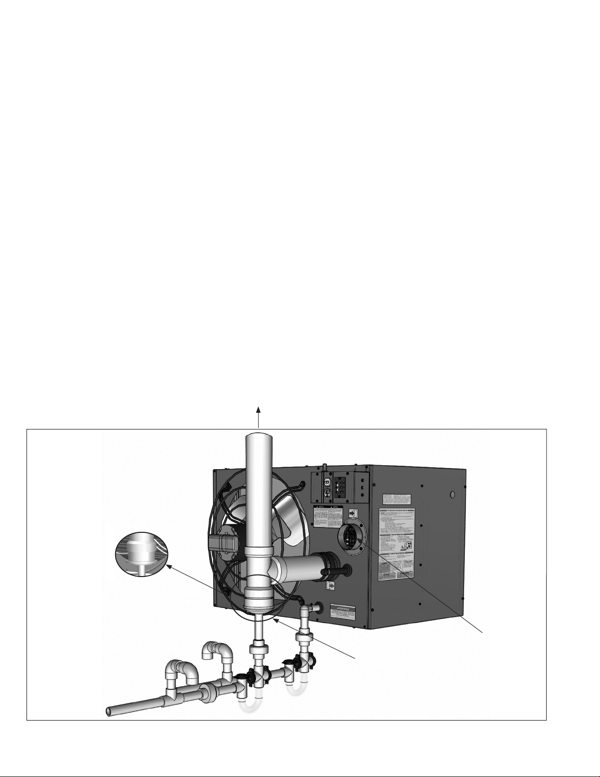
B3. It is required to install a tee with drip leg and clean out cap
as shown in Figure 8.1. Please note the following
requirements:
a. Only the vent system drip leg and condensate removal
drain connections are shown. Vent and combustion air
piping must be terminated per the instructions in this
manual, for either 2-pipe or vertical concentric vent
arrangements. All venting and drain components, except
condensate traps, are by others.
b. The standard vent drip leg and drain shown for U.S.
ONLY installations utilizes a standard, non-sweep tee,
sized to match the vent diameter for the model size (see
Table 6.1). The tee captures and directs the condensate
to a cap that is drilled and fitted with a 3/4" fitting for
connection to the condensate drain. For installation in
Canada, see Note B3c.
c. The vent drip leg for Canadian installations must be
approved to ULC S636. This requires the use of a
series of reducers from the outlet of the tee to the drain
connection. Drilling or otherwise modifying the shape or
structure of any vent components is not allowed per ULC
S636. Note that the 3/4" condensate drain piping and
condensate traps are not subject to the ULC S636
requirements that apply to the vent system. This method
is also acceptable in US installations.
d. Connection of a combustion air inlet pipe is required to
be connected from the building exterior (not shown in
Figure 8.1).
e. Condensate drains are required for both the unit heater
and the vent system. Properly sized traps are included
with the unit. Proper drain design and installation is
critical to ensure that the unit and vent systems are
properly drained. Refer to the section titled “Condensate
Drain and Trap Installation” on page 13 for detailed
instructions.
B4. If a concentric vent system is to pass through one
common hole in the roof, please proceed at this point to
“Section D - Horizontal and Vertical Concentric Venting” for
instructions. Otherwise, proceed to note B5 for instructions
on terminating a 2-pipe installation.
B5. For 2-pipe vertical configurations, refer to the following
instructions and Figure 9.1 with minimum distances as
shown.
B6. The combustion air inlet and vent pipes must each be
terminated with two 90° elbows with screened openings
(four elbows total). The screens are available from Modine
as part of a kit. For model sizes 260 and smaller, the 4
elbows are to be PVC. For model size 310, the vent pipe
is to be terminated with 2 PVC elbows and the combustion
air inlet pipe is to be terminated with 2 galvanized or other
approved corrosion resistant metal elbows.
B7. The combustion air inlet and vent pipe terminations must
be positioned in opposite directions.
B8. Once venting is complete, proceed to the section titled
“Condensate Drain and Trap Installation” on page 13.
Figure 8.1 - Vertical Venting System Drip Leg and Condensate Drain Connections
To Building Exterior (refer to Note B3.a.)
Drip Leg for Canada
(Alternate for US)
(refer to Note B3.c.)
Drain and trap to
sanitary sewer
connection for
condensate removal ➀
(refer to Note B3.e.)
Standard Vent
Drip Leg for
US ONLY
(refer to Note B3.b.)
Combustion Air Inlet
Pipe Connector
(refer to Note B3.d.)
jProper drain design and installation is critical to ensure that the unit and vent systems are properly drained.
8
6-563.9
Page 9
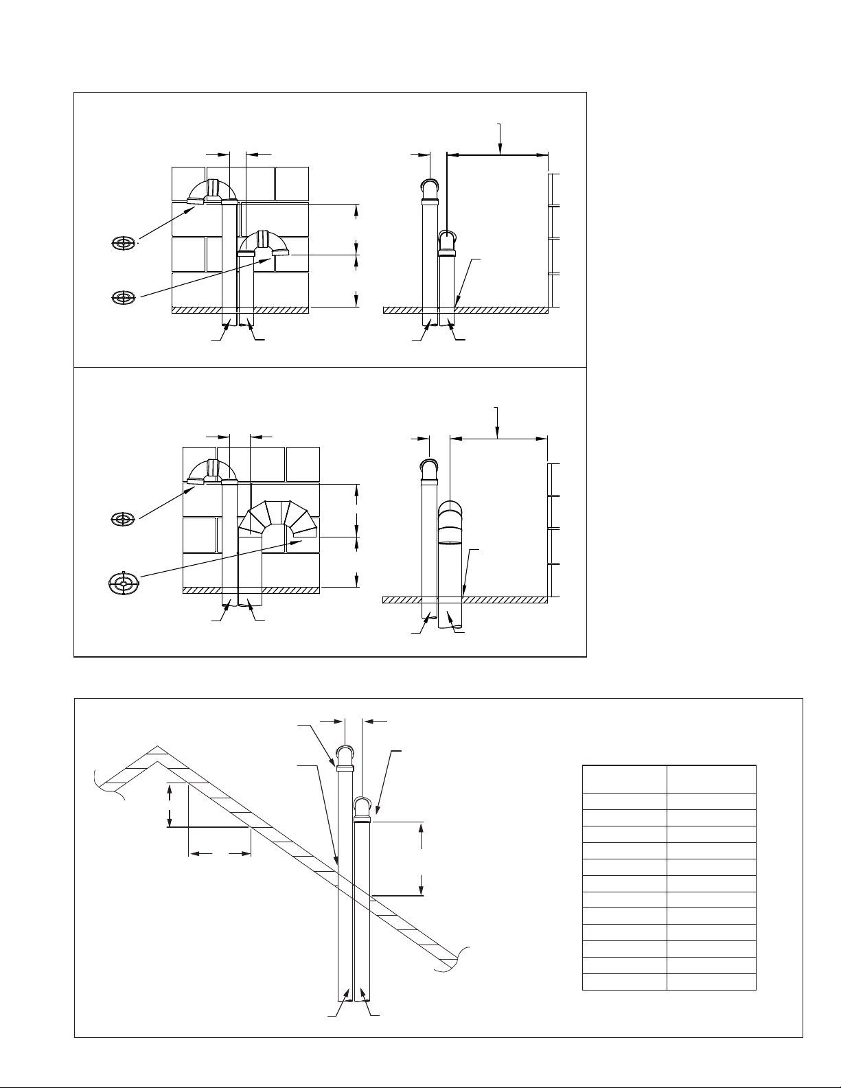
INSTALLATION - VENTING
24" Minimum from adjacent
Figure 9.1 - Vertical 2-Pipe Vent System for Flat Roofs
MODEL SIZES 55 THROUGH 260
wall or building to Combustion
4.5" Minimum
4.5" Minimum
8" Minimum (135-215)
14" Minimum (260)
Air Inlet Pipe Terminal
Termination Screens
(refer to Note B6)
Termination Screens
(refer to Note B6)
Vent Pipe
Vent Pipe
above roof or snow line
Combustion Air
Inlet Pipe
MODEL SIZE 310
4.5" Minimum
12" Minimum above
Combustion Air
Inlet Pipe
12" Minimum
Vent Pipe
4.5" Minimum
14" Minimum
roof or snow line
Vent Pipe
Combustion Air
Inlet Pipe
24" Minimum from adjacent
wall or building to Combustion
Air Inlet Terminal Opening
through the roof
Combustion Air
Inlet Pipe
Roof flashing
required at all
penetrations
through the roof
Roof flashing
required at all
penetrations
Figure 9.2 - Vertical 2-Pipe Vent System for Sloped Roofs
For vent outlet opening
distance above combustion
air intake opening,
refer to Figure 9.1
X
12"
Roof flashing
required at all
penetrations
through roof
Vent Outlet
Pipe
4.5" Minimum
Combustion air intake pipe shown
for model sizes 85 through 260.
For model size 310, pipe is 6"
galvanized or corrosion resistant metal
Minimum Height "H"
Based on Table 9.2
to inlet opening
Combusion Air
Inlet Pipe
6-563.9
Table 9.2 - Minimum Height
from Roof to Lowest
Discharge Opening
Rise “X”
(in) j
Over 0 to 6 1.00
Over 6 to 7 1.25
Over 7 to 8 1.50
Over 8 to 9 2.00
Over 9 to 10 2.50
Over 10 to 11 3.25
Over 11 to 12 4.00
Over 12 to 14 5.00
Over 15 to 16 6.00
Over 16 to 18 7.00
Over 18 to 20 7.50
Over 20 to 21 8.00
jRise X/12 corresponds to the roof pitch
(e.g. X=9 is 9/12 pitch).
k Size according to snow depth.
Minimum “H”
(ft) k
9
Page 10
INSTALLATION - VENTING
Section C - Horizontal Vent System Installation
C1. This section applies to horizontally vented 2-pipe vent
systems (1 combustion air inlet pipe and 1 vent pipe) and
concentric (single wall penetration) and is in addition to
“Section A - General Instructions - All Units”.
C2. Horizontal vent systems terminate horizontally (sideways).
C3. It is required to install a tee with drip leg and clean out cap
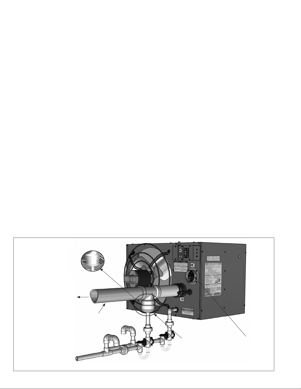
as shown in Figure 10.1. Please note the following
requirements:
a. Only the vent system drip leg and condensate removal
drain connections are shown. Vent and combustion air
piping must be terminated per the instructions in this
manual, for either 2-pipe or horizontal concentric vent
arrangements. All venting and drain components, except
condensate traps, are by others.
b. The standard vent drip leg and drain shown for US ONLY
installations utilizes a tee, sized to match the vent diameter
for the model size (see Table 6.1). The tee captures and
directs the condensate to a cap that is drilled and fitted
with a 3/4” fitting for connection to the condensate drain.
For installation in Canada, see Note C3c.
c. The vent drip leg for Canadian installations must be
approved to ULC S636. This requires the use of a series
of reducers from the outlet of the tee to the drain
connection. Drilling or otherwise modifying the shape or
structure of any vent components is not allowed per
ULC S636. Note that the 3/4" condensate drain piping
and condensate traps are not subject to the ULC S636
requirements that apply to the vent system. This method
is also acceptable in US installations.
d. Connection of a combustion air inlet pipe is required to
be connected from the building exterior (not shown in
Figure 10.1)
e. A condensate drain each is required from the unit heater
and the vent system. Properly sized traps are included
with the unit. Proper drain design and installation is
critical to ensure that the unit and vent systems are
properly drained. Refer to the section titled “Condensate
Drain and Trap Installation” on page 13 for detailed
instructions.
C4. If a concentric vent system is to pass through one
common hole in the wall, please proceed at this point to
“Section D - Horizontal and Vertical Concentric Venting”
for instructions. Otherwise, proceed to note C5 for
instructions on terminating a 2-pipe installation.
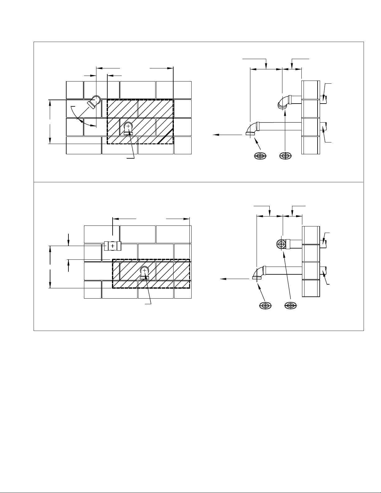
C5. For 2-pipe horizontal configurations, refer to the following
instructions and Figure 11.1 with minimum distances as
shown.
C6. The vent pipe for all sizes except 260 must be terminated
with a PVC 90° elbow with screened opening. The vent
pipe for model size 260 must be terminated with a PVC
tee with screened openings. These screens are available
from Modine as part of a kit.
C7. For all sizes except 260, the elbow is to be installed on
the vent pipe outlet so that the elbow is at a 45° angle
with the opening facing away from the combustion air
inlet pipe. For model size 260 units, the tee is to be
installed horizontally so that the openings of the tee face
right and left.
C8. The combustion air inlet pipe termination is to be a 90°
elbow with screened opening. These screens are
available from Modine as part of a kit. For model sizes
260 and smaller, the elbow is to be PVC. For model size
310, the elbow is to be galvanized or other approved
corrosion resistant metal elbow.
C9. The elbow is to be installed on the combustion air inlet
pipe with the opening of the elbow facing down.
C10. When condensation may be a problem, the vent system
shall not terminate over public walkways or over an area
where condensate or vapor could create a nuisance or
hazard or could be detrimental to the operation of
regulators, relief openings, or other equipment.
C11. Maintain a 1/4" per foot upward slope away from the
heater and place a drip leg with clean out near the vent
connector on the heater as shown in Figure 10.1.
C12. For a vent termination located under an eave, the
distance of the overhang must not exceed 24". The
clearance to combustibles above the exterior vent must
be maintained at a minimum of 12". Consult the National
Fuel Gas Code for additional requirements for eaves that
have ventilation openings.
C13. Once venting is complete, proceed section titled
“Condensate Drain and Trap Installation” on page 13.
Figure 10.1 - Horizontal Venting System Drip Leg and Condensate Drain Connections
Drip Leg for Canada
(Alternate for US)
(refer to Note C3.c.)
To Building
Exterior
(refer to
Note C3.a.)
Pitch vent pipe
up 1/4" per foot
(refer to Note C11)
Drain and trap to
sanitary sewer
connection for
condensate removal.➀
(refer to Note C3.e.)
jProper drain design and installation is critical to ensure that the unit and vent systems are properly drained.
Standard Vent
Drip Leg for
US ONLY
(refer to Note C3.b.)
Combustion Air Inlet
Pipe Connector
(refer to Note C3.d.)
10
6-563.9
Page 11
INSTALLATION - VENTING
Figure 11.1 - Horizontal 2-Pipe Vent System
MODEL SIZES 55 THROUGH 215 & 310
42" Maximum
6" Minimum
45°
18" Minimum from
Vent Terminal to
Combustion Air Inlet
Terminal opening
9" Minimum from
wall to Vent
Terminal opening
Vent Pipe
24" Maximum
6" Minimum
24" Maximum
The center-line of the
combustion air inlet pipe
must be within the shaded area
42" Maximum
24" Minimum to
adjacent wall or
MODEL SIZE 260
building
18" Minimum from
Vent Terminal to
Combustion Air Inlet
Terminal opening
24" Minimum to
adjacent wall or
building
Termination Screens
(refer to Notes
C6 and C8)
Combustion
Air Inlet Pipe
9" Minimum from
wall to Vent
Terminal opening
Vent Pipe
Combustion
Air Inlet Pipe
The center-line of the
combustion air inlet pipe
must be within the shaded area
6-563.9
Termination Screens
(refer to Notes
C6 and C8)
x 2 (both ends of tee)
11
Page 12
INSTALLATION - VENTING
Section D - Concentric Vent System
Installation
D1. This section applies to both horizontally and vertically
vented concentric vent systems as defined in “Section A General Instructions - All Units”. The required instructions
that must be followed are as follows:
For Vertical Concentric Vented Units:
•SectionA-GeneralInstructions-AllUnits
•SectionB-VerticalVentSystemInstallation,stepsB1-B4
•Applicableinstructionsinthissection
For Horizontal Concentric Vented Units:
•SectionA-GeneralInstructions-AllUnits
•SectionC-HorizontalVentSystemInstallation,stepsC1-C4
•Applicableinstructionsinthissection
D2. When utilizing the concentric vent option, it should have
been predetermined whether the appliance will be
horizontally or vertically vented. Before proceeding, verify
that the concentric vent kit received contains the correct
components for the installation:
For Vertically Vented Units (Refer to Figure 12.1):
j Concentric Adapter Assembly
k Vent Pipe Terminal Screens
l Combustion Air Inlet Pipe Terminal
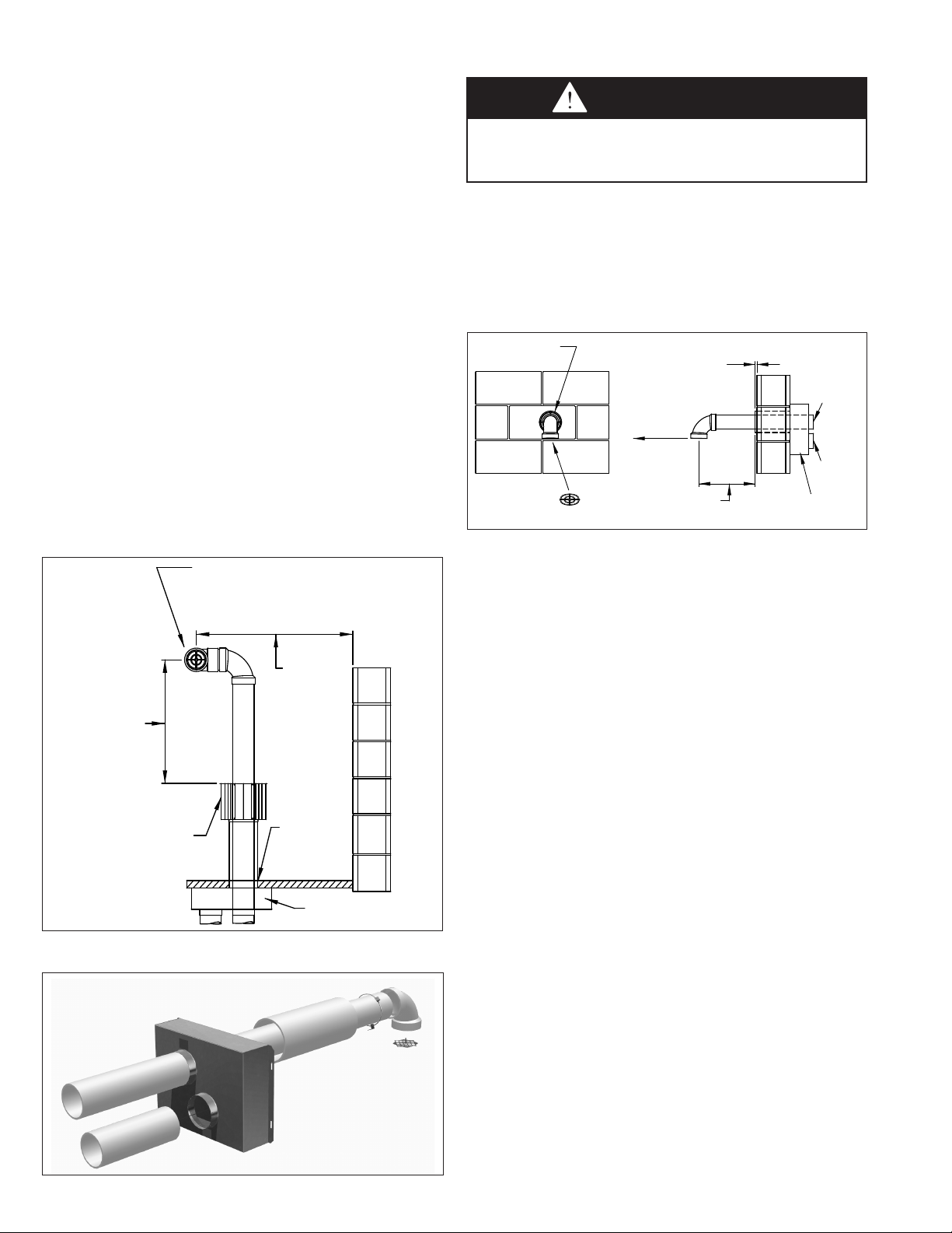
Figure 12.1 - Vertical Concentric Vent Kit
Vent Pipe Termination
Consisting of the Following:
(1) PVC 90° Elbow,
(1) PVC Tee (Horizontal),
(2) Termination Screens
(both ends of tee)
24" Minimum
from adjacent
wall or building
24" above
Combustion
Air Inlet Pipe
Terminal
Combustion Air
Inlet Pipe Terminal
Figure 12.2 - Adapter Box Exploded Assembly
Roof flashing
required at all
penetrations
through the roof
Concentric Vent
Adapter Box
CAUTION
The concentric vent adapter box must be installed inside of
the structure or building. Do not install this box on the exterior
of a building or structure.
For Horizontally Vented Units (Refer to Figure 12.3):
j Concentric Adapter Assembly
k Vent Pipe Terminal Screen
l Special Inlet Air Guard
Figure 12.3 - Horizontal Concentric Vent Kit
Combustion Air Inlet
Pipe Termination Guard
Termination Screen
D3. Once the kit contents have been verified as correct for the
direction of venting, the concentric vent adapter box is to be
installed. Determine the location of the box. Be sure to
maintain all dimensions as listed in these instructions.
D4. The adapter box is to be mounted on the interior side of the
building. It must not be mounted outside the building.
D5. The adapter box can be mounted flush to the wall (for
horizontal kits) or to the ceiling (for vertical kits). When
mounting the box, consider serviceability and access to the
vent and combustion air pipes.
D6. Determine the length of the combustion air pipe that must
be attached to the combustion air inlet (on the concentric
side) of the adapter box to extend through the building wall
or roof. Be sure to add the length of the thickness of the
wall or roof. Refer to Figures 12.1 or 12.2 to determine the
required minimum distance to the termination from the roof
or wall.
D7. Cut the concentric side combustion air pipe to the proper
length as determined in the previous step. Refer to Table
6.1 for pipe diameters and material.
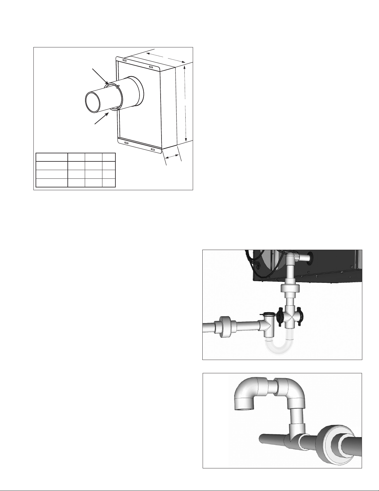
D8. Attach the concentric side combustion air pipe to the air
inlet of the concentric adapter box, as shown in Figure 13.1,
using at least 3 corrosion-resistant sheet metal screws.
Seal the joint using caulk.
D9. Place this assembly (the adapter box and combustion air
pipe) through the wall or roof and verify that the distance
requirements as defined in Step D6 are met. Securely
attach the assembly to the building using the brackets on
the adapter box.
D10. From outside the building, caulk the gap between the
combustion air intake pipe and the building penetration.
1" from wall to
Combustion Air
Inlet Pipe Terminal opening
24" Minimum to
adjacent wall or
building
14" Minimum from
Combustion Air Inlet
Pipe Terminal
Vent Pipe
Combustion
Air Inlet
Concentric Vent
Adapter Box
Pipe
12
6-563.9
Page 13
INSTALLATION - VENTING & CONDENSATE DRAIN
Figure 13.1 - Adapter Box with Combustion Air
Intake Pipe Attached
Combustion Air
Pipe Attached
(See Dimension C)
Combustion Air
Intake Guard j
Model Size A B C
55-135 12.25" 14.63" 6"
156-260 13.39" 18.88" 6"
310 15.27" 17.00" 8"
jFor reference only for horizontal concentric vent arrangements.
D11. Install the vent pipe by extending the vent pipe all the way
through the concentric vent adapter assembly. Seal the
adapter around the pipe using caulk.
D12. Attach the combustion air intake and vent pipe
terminations as follows:
For Vertical Concentric Vent Kits
A
B
4.57"
(refer to Figure 12.1):
•Slidethecombustionaircapdownovertheventpipe
and fasten it to the combustion air pipe with at least
3 corrosion-resistant sheet metal screws.
•Terminatetheventpipewithaelbow/teecombination
with guards.
•Caulkthegapbetweenthecombustionaircapandthe
vent pipe with silicone sealant or other appropriate caulk.
For Horizontal Concentric Vent Kits
(refer to Figure 12.3):
•Attachthecombustionairintakeguardusingcorrosion
resistant screws at the end of the combustion air intake
pipe to prevent animals and debris from entering (see
Figure 13.1).
•Solventweld(glue)theventtermination(elbowortee)to
the vent pipe.
•Installtheventscreen(s)intheelbowortee.
D13. Install the vent and combustion air pipe between unit
heater and concentric vent adapter box as outlined in
“Section A – General Instructions – All Units”.
D14. Once venting is complete, proceed to the following section
titled “Condensate Drain and Trap Installation”.
2. Local code permitting, the condensate drain systems may be
joined after the traps and connected to a sanitary drain
within the building. Because the condensate produced is
acidic, some municipalities may require that the condensate
be neutralized before being discharged into the sanitary
sewer. A condensate neutralizer tube kit is available from
Modine to reduce the pH of the condensate. A separate
neutralizer tube is required for both the vent drain and the
heater drain, but a single tube can be used for drains that
are joined after the traps providing the tube is installed after
the junction. Refer to the instructions that come with the kit.
3. Unions are recommended to permit maintenance of the
drains and to facilitate service of the heater. A union is
shown on both sides of each trap.
4. Connect the threaded side of the PVC elbow supplied to the
secondary heat exchanger condensate drain with the socket
connection oriented as shown in Figures 8.1 and 10.1.
5. A vacuum breaker is required after each trap as shown in
Figures 8.1 and 10.1. The vacuum breaker should be
constructed so that dirt and debris do not enter and clog the
drain system.
6. For safe operation, the traps should be primed with water.
The traps must be installed with the higher side connected to
the heater and the lower side connected to the drain.
7. If there is an opportunity that the temperature in the space
will fall below freezing during non-operating periods, the
condensate drain systems and secondary heat exchanger
must be completely drained to prevent freeze damage.
Alternately, heat tape can be applied to the drain pipe
system in accordance with the heat tape manufacturers
instructions.
8. Once the condensate drain lines are complete, proceed to
the following section, “Installation - Gas Connections”.
Figure 13.2 - Drain Trap
Figure 13.3 - Vacuum Breaker Example
Condensate Drain and Trap Installation
During operation, condensate is both produced in the heater
and the venting system. The installation requires condensate
drain systems from the secondary heat exchanger and from the
vent pipe. A condensate trap kit is provided with the unit and
consists of 2 specially designed traps and 1 PVC elbow for the
unit condensate drain connection.
1. For proper heater and vent system performance, the
condensate drain system must include a trap for each as
shown in Figure 8.1 and Figure 10.1. All joints must be
watertight to prevent leakage of condensate.
6-563.9
13
Page 14
INSTALLATION - GAS CONNECTIONS
GAS
SUPPLY LINE
GAS
SUPPLY LINE
GROUND
JOINT
UNION
MANUAL
SHUT-OFF
VALVE
3"
MIN.
SEDIMENT
TRAP
PLUGGED
1/8" NPT TEST
GAUGE CONNECTION
TO
CONTROLS
GAS CONNECTIONS
WARNING
1. Installation must conform with local building codes or in
the absence of local codes, with the National Fuel Gas
Code, ANSI Z223.1 (NFPA 54) - latest edition. In Canada
installation must be in accordance with CSA B149.1.
2. All field gas piping must be pressure/leak tested prior to
operation. Never use an open flame. Use a soap solution
or equivalent for testing.
3. Gas pressure to appliance controls must never exceed
14" W.C. (1/2 psi).
4. To reduce the opportunity for condensation, the minimum
sea level input to the appliance, as indicated on the serial
plate, must not be less than 5% below the rated input, or
5% below the minimum rated input of dual rated units.
CAUTION
1. Purging of air from gas lines should be performed as
described in the National Fuel Gas Code, ANSI Z223.1
(NFPA 54) - latest edition, or in Canada CSA-B149 codes.
2. When leak testing the gas supply piping system, the
appliance and its combination gas control must be isolated
during any pressure testing in excess of 14" W.C. (1/2 psi).
3. The unit should be isolated from the gas supply piping
system by closing its field installed manual shut-off
valve.This manual shut-off valve should be located within
6' of the heater.
4. Turn off all gas before installing appliance.
IMPORTANT
To prevent premature heat exchanger failure, the input to
the appliance, as indicated on the serial plate, must not
exceed the rated input by more than 5%.
1. Installation of piping must conform with local building codes,
or in the absence of local codes, with the National Fuel Gas
Code, ANSI Z223.1 (NFPA 54) - latest Edition. In Canada,
installation must be in accordance with CSA-B149.1.
2. Piping to units should conform with local and national
requirements for type and volume of gas handled, and
pressure drop allowed in the line. Refer to Table 14.1 to
determine the cubic feet per hour (CFH) for the type of gas
and size of unit to be installed. Using this CFH value and the
length of pipe necessary, determine the pipe diameter from
Table 14.2. Where several units are served by the same
main, the total capacity, CFH and length of main must be
considered. Avoid pipe sizes smaller than 1/2". Table 14.2
allows for a 0.3" W.C. pressure drop in the supply pressure
from the building main to the unit. The inlet pressure to the
unit must be 6-7" W.C. for natural gas and 11-14" W.C. for
propane gas. When sizing the inlet gas pipe diameter, make
sure that the unit supply pressure can be met after the 0.3"
W.C. has been subtracted. If the 0.3" W.C. pressure drop is
too high, refer to the Gas Engineer’s Handbook for other gas
pipe capacities.
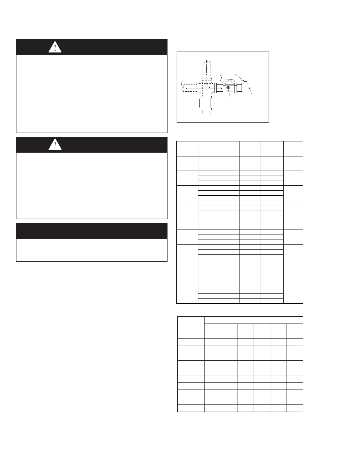
3. Install a ground joint union with brass seat and a manual
shut-off valve adjacent to the unit for emergency shut-off and
easy servicing of controls, including a 1/8" NPT plugged
tapping accessible for test gauge connection (see Figure 14.1).
4. Use 2 wrenches when connecting field piping to units.
5. Provide a sediment trap before each unit in the line where
low spots cannot be avoided. (see Figure 14.1).
6. When pressure/leak testing, pressures above 11" W.C.
(1/2 psi), close the field installed shut-off valve, disconnect
the appliance and its combination gas control from the gas
supply line, and plug the supply line before testing. When
testing pressures 14" W.C. (1/2 psi) or below, close the
manual shut-off valve on the appliance before testing.
14
Figure 14.1 - Recommended Sediment Trap/Manual
Shut-off Valve Installation - Side or Bottom Gas
Connection j
jManual shut-off valve is in
the “OFF” position when
handle is perpendicular
Table 14.1 - Sea Level Manifold Pressure &
Gas Consumption
Model
Size
55
65
85
110
135
156
180
215
260
310
Manifold Pressure
("W.C.):
CFH 54.0 22.1
Gal/Hr. Propane n/a 0.61
Orifice Drill Size 50 1.10 mm
CFH 65.6 26.3
Gal/Hr. Propane n/a 0.73
Orifice Drill Size 1.75 mm 57
CFH 81.0 34.0
Orifice Drill Size 47 1.25 mm
CFH 105.0 44.0
Orifice Drill Size 43 54
CFH 128.6 54.0
Orifice Drill Size 43 54
CFH 147.6 62.0
Orifice Drill Size 41 1.50 mm
CFH 171.4 72.0
Orifice Drill Size 41 53
CFH 204.8 86.0
Orifice Drill Size 42 54
CFH 247.6 104.0
Orifice Drill Size 38 52
CFH 295.2 124.0
Gal/Hr. Propane n/a 3.4
Orifice Drill Size 41 53
Natural Propane
3.5 10
# of
Orifices
4
5
5Gal/Hr. Propane n/a 0.9
5Gal/Hr. Propane n/a 1.2
6Gal/Hr. Propane n/a 1.5
6Gal/Hr. Propane n/a 1.7
7Gal/Hr. Propane n/a 2.0
9Gal/Hr. Propane n/a 2.4
9Gal/Hr. Propane n/a 2.9
12
Table 14.2 - Gas Pipe Capacities - Natural Gas jk
Pipe
Length (ft.)
1/2" 3/4" 1" 1-1/4" 1-1/2" 2"
10 132 278 520 1050 1600 3050
20 92 190 350 730 1100 2100
30 73 152 285 590 890 1650
40 63 130 245 500 760 1450
50 56 11 5 215 440 670 1270
60 50 105 195 400 610 1150
70 46 96 180 370 560 1050
80 43 90 170 350 530 930
100 38 79 150 305 460 870
125 34 72 130 275 410 780
150 31 64 120 250 380 710
jCapacities in cubic feet per hour through Schedule 40 pipe with maximum
0.3" W.C. pressure drop with up to 14" W.C. gas pressure. Specific gravity is 0.60
for natural gas and 1.50 for propane gas.
k For pipe capacity with propane gas, divide natural gas capacity by 1.6. Example:
What is the propane gas pipe capacity for 60 feet of 1-1/4" pipe? The natural gas
capacity is 400 CFH. Divide by 1.6 to get 250 CFH for propane gas.
Natural Gas
6-563.9
Page 15
INSTALLATION - HIGH ALTITUDE ACCESSORY KIT
HIGH ALTITUDE ACCESSORY KIT
Modine’s gas-fired equipment standard input ratings are
certified by ETL. For elevations above 2,000', ANSI Z223.1
requires ratings be reduced 4 percent for each 1,000' above sea
level. For units in Canada, CSA requires that ratings be reduced
10 percent at elevations above 2,000' The high altitude
adjustment instructions and pressure switch kits listed
in this manual are for use with units that will be installed over
2,000'. These methods and kits comply with both ANSI Z223.1
and CSA requirements.
If a unit is to be installed at higher elevations AND converted from
natural gas to propane gas operation, a propane conversion kit
must be used in conjunction with the pressure adjustment
methods and pressure switch kits listed herein. For the Selection
and Installation Instructions for propane conversion kits, please
see the latest revision of Modine Manual 75-515.
Selection of the Proper Pressure and Kit
To determine the proper manifold pressure at altitude and if
required, the proper combustion air pressure switch kit, the full
model number of the heater, the fuel to be used, and the
altitude the unit will be installed at must be known. Refer to the
unit serial plate or carton label to obtain the necessary
information about the unit.
After obtaining this information, refer to the gas pressure and
selection charts shown in Tables 15.1 through 15.3. The pressure
charts are differentiated by elevation, fuel type, and country
the product is being installed in. The selection charts are
differentiated by product type, altitude and fuel type. If
converting from natural gas to propane gas and operation
at high altitude, both a propane conversion kit and a
pressure switch kit must be used (if applicable). Selection
charts include the proper kit suffix, when required.
Manifold Pressure Adjustment
The inlet pressure to the unit must be confirmed to be within
acceptable limits (6-7" W.C. for natural gas and 11-14" W.C.
for propane gas) before opening the shutoff valve or the
combination gas valve may be damaged.
Heaters for use with natural gas. 3.5" W.C. manifold pressure
at 7.0" W.C. inlet pressure.
Units for use with propane gas. 10.0" W.C. manifold pressure
at 14.0" W.C. inlet pressure.
Installation above 2,000'. elevation requires adjustment of the
manifold pressure as described.
Derated BTU Content Gas and Manifold Pressure
Calculation
Some utility companies may derate the BTU content (heating
value) of the gas provided at altitude to a value other than 1,050
BTU/ft3 for natural gas or 2,500 BTU/ft3 for propane gas to allow
certain heating appliances to be used with no manifold pressure
adjustments. For this reason it is necessary that the supplying
utility be contacted for detailed information about the gas type
and BTU content (heating value) before operating any heater.
Tables 15.1 and 15.2 show the standard derated heating values
(4% per 1,000' of elevation in the USA and 10% between 2,001'
and 4,500' elevation in Canada) of natural and propane gases
at various altitudes. If the utility is supplying gas with heating
values as shown in Tables 15.1 and 15.2, the manifold pressure
should be set to 3.5" W.C for natural gas and 10.0" W.C. for
propane gas.
NOTE: Only the high fire gas pressure need be adjusted; low
fire gas pressure should remain the same.
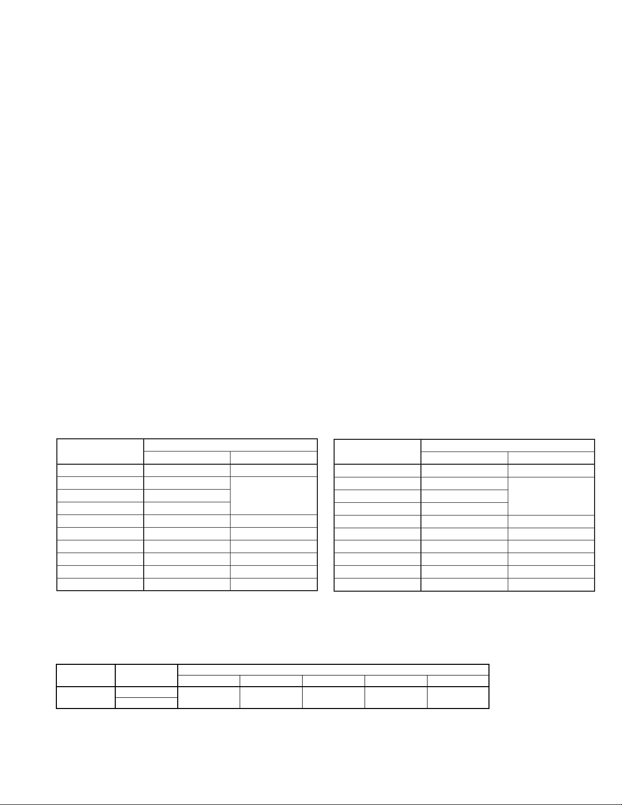
Table 15.1 - Natural Gas Heating Values at
Altitude ➀➂➃
Altitude (ft)
0-2,000 1,050 1,050
2,001-3,000 929
4,001-4,500 874
4,501-5,000 856 856
5,001-6,000 822 822
6,001-7,000 789 789
7,001-8,000 757 757
8,001-9,000 727 727
9,001-10,000 698 698
➀Values shown are for 3.5" W.C. manifold pressure, for other BTU content values (available from local utility) use Equation 16.1 to calculate manifold pressure.
➁Values shown are for 10.0" W.C. manifold pressure, for other BTU content values (available from local utility) use Equation 16.1 to calculate manifold pressure.
➂When installed at altitudes above 2,000', a pressure switch may need to be changed. Refer to Table 15.3 to determine if a switch change is required.
➃Gas heating values are derated 4% per 1,000' of elevation in the USA and 10% between 2,000' and 4,500' elevation in Canada in accordance with ANSI Z223.1
and CSA-B149, respectively.
Gas Heating Values at Altitude (BTU/ft3)
USA Canada
9453,001-4,000 892
Table 15.2 - Propane Gas Heating Values at
Altitude ➁➂➃
Altitude (ft)
0-2,000 2,500 2,500
2,001-3,000 2,212
4,001-4,500 2,080
4,501-5,000 2,038 2,038
5,001-6,000 1,957 1,957
6,001-7,000 1,879 1,879
7,001-8,000 1,803 1,803
8,001-9,000 1,731 1,731
9,001-10,000 1,662 1,662
Gas Heating Values at Altitude (BTU/ft3)
USA Canada
2,2503,001-4,000 2,123
Table 15.3 - High Altitude Kits for PTC/BTC ➀
Model Size Details
55-310
➀ForLabelOnlykits,Modinepartnumber5H0807146005isrequiredtobelledoutandattachedtotheunitbytheinstaller.
Please contact the local Modine representative at 1.866.828.4328 (HEAT).
Kit Suffix
Item Code
0-2,000 ft 2,001-4,500 ft 4,501-5,500 ft 5,501-6,500 ft 6,501-7,500 ft
Not Required Label Only Label Only Label Only Label Only
U.S.A. and Canada
6-563.9
15
Page 16
INSTALLATION - HIGH ALTITUDE ACCESSORY KIT
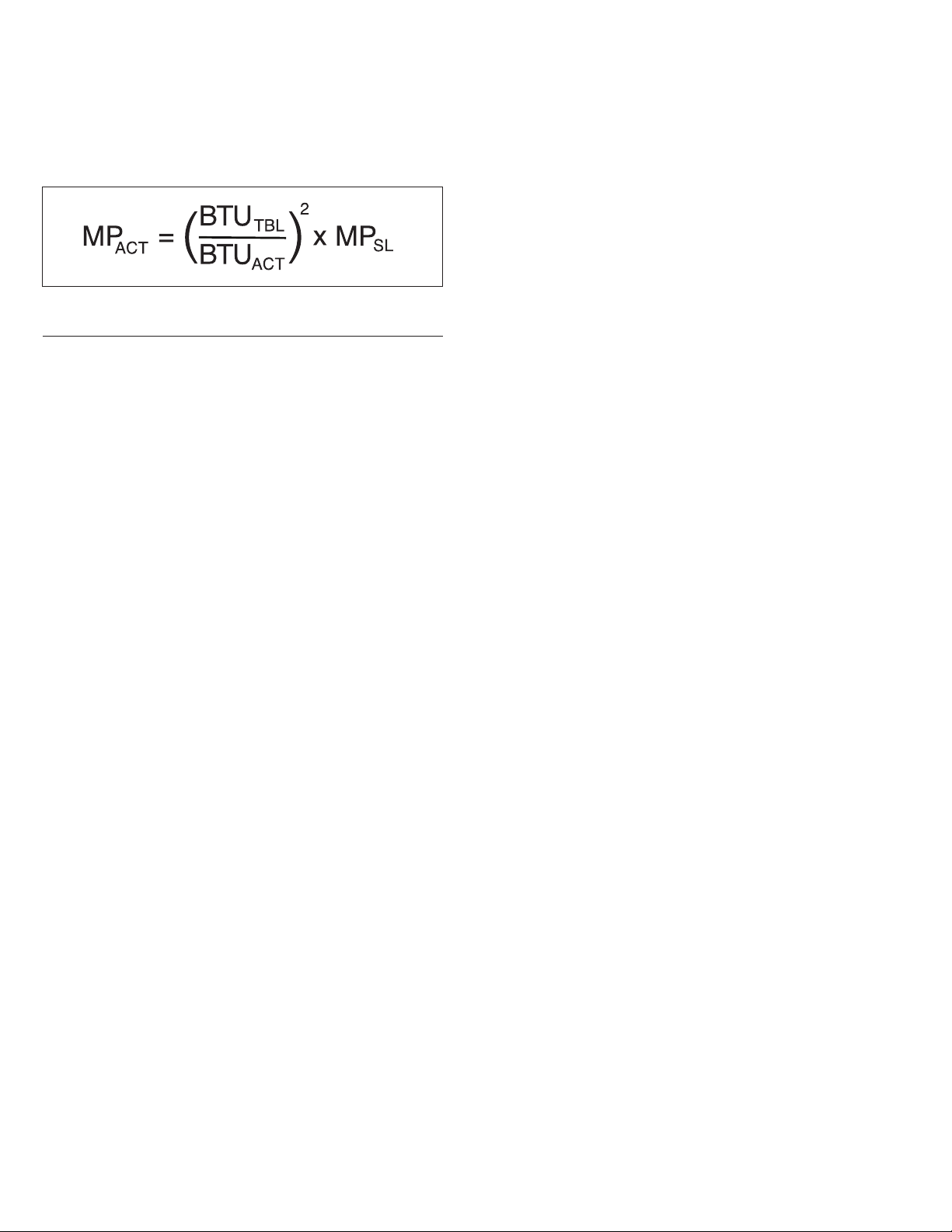
If the heating value of the gas being supplied is different than
the values shown in Tables 15.1 and 15.2, use the following
equation to determine the appropriate manifold pressure for the
altitude and gas heating value being supplied.
Equation 16.1 - Manifold Pressure for Derated Gas
WHERE:
MP
= Manifold Pressure (in. W.C.) at Altitude –
ACT
BTU
BTU
MPSL = Manifold Pressure (in. W.C.), at Sea Level –
NOTE: Only the primary manifold pressure should be adjusted
on units equipped with two-stage or modulating gas controls.
No adjustments to the low fire manifold pressure are necessary
on these units.
Manifold pressure setting for the heater being
installed
= BTU/ft3 Content of Gas –
TBL
Obtained from Tables 15.1 or 15.2 (whichever is
applicable)
= BTU/ft3 Content of Gas –
ACT
Obtained from the local utility company
Use 3.5" W.C. for natural has and 10.0" W.C. for
propane gas
16
6-563.9
Page 17
INSTALLATION - ELECTRICAL CONNECTIONS
ELECTRICAL CONNECTIONS
WARNING
1. Disconnect power supply before making wiring connections
to prevent electrical shock and equipment damage.
2. All appliances must be wired strictly in accordance with
wiring diagram furnished with the appliance. Any wiring
different from the wiring diagram could result in a hazard
to persons and property.
3. Any original factory wiring that requires replacement must
be replaced with wiring material having a temperature
rating of at least 105°C.
4. Ensure that the supply voltage to the appliance, as
indicated on the serial plate, is not 5% greater than or
5% less than the rated voltage.
1. Installation of wiring must conform with local building codes, or in
the absence of local codes, with the National Electric Code ANSI/
NFPA 70 - Latest Edition. Unit must be electri cally grounded in
conformance to this code. In Canada, wiring must comply with
CSA C22.1, Part 1, Electrical Code.
2. Two copies of the unit wiring diagram are provided with each unit.
One is located in the side access control compartment and the
other is supplied in the literature packet. Refer to this diagram for
all wiring connections.
3. Make sure all multi-voltage components (motors, transform ers,
etc.) are wired in accordance with the power supply voltage.
4. The power supply to the unit must be protected with a fused or
circuit breaker switch.
5. The power supply must be within 5 percent of the voltage rating
and each phase must be balanced within 2 percent of each other.
If not, advise the utility company.
6. External electrical service connections that must be installed
include:
a. Supply power connection (115, 208, 230, 460, or 575 volts).
b. Connection of thermostats, or any other accessory control
devices that may be supplied (24 volts).
NOTE: All units with supply voltage 208V and greater must use a
field installed step-down transformer, available as a separate
accessory. Refer to Tables 17.1 and 17.2 for additional
information on the required transformer.
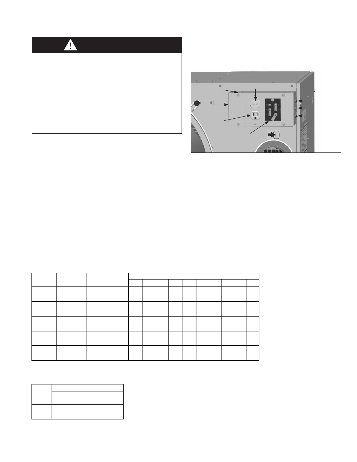
7. Refer to Figure 17.1 for the junction box wiring entry location.
Figure 17.1 - Power/Control Wiring
Supply Power
Conduit Entry
Knockouts
Condensate
Pump Outlet
8. All supply power electrical connections are made in the junction
box compartment of the unit. The low voltage (thermostat and
accessory control devices) can be wired to the terminals on the
junction box.
Unit On/Off Switch
Terminal Board
for Low Voltage
Control Wiring
Unit Status
Lights:
Green =
Power On
Amber =
Call for Heat
Blue =
Burner On
Additional Notes for the Condensate Pump Outlet:
9. The condensate pump outlet supplied with this unit is intended for
use with a condensate pump with operating amps not to exceed
2 Amps.
10. The condensate pump cutlet can be used as a service outlet. To
be used as a service outlet, the on/off toggle switch located
above the outlet must be in the OFF position to disable the unit
heater power and gas control circuits to prevent equipment
damage. When the unit is wired directly to a 115V power supply,
the outlet is rated for a maximum load of 20 amps at 115V. If this
unit has been provided with an accessory step-down transformer
to 115V from a higher supply voltage, ensure that the load
plugged into the outlet does not exceed 8A for 1.0kVA or 12A for
1.5kVA rated transformers.
Table 17.1 - Propeller Unit Model PTC Accessory Transformer Size
Supply
Voltage
115V
1 Phase
208V
1 or 3
Phase
230V
1 or 3
Phase
460V
3 Phase
575V
3 Phase
Power
Code
01 (115V) Transformer kVA n/a n/a n/a n/a n/a n/a n/a n/a n/a n/a
01 (115V)
with
Transformer
01 (115V)
with
Transformer
01 (115V)
with
Transformer
01 (115V)
with
Transformer
Transformer kVA 1.00 1.00 1.00 1.00 1.00 1.00 1.00 1.50 1.50 1.50
Transformer kVA 0.75 0.75 0.75 1.00 1.00 1.00 1.00 1.50 1.50 1.50
Transformer kVA 0.75 0.75 0.75 1.00 1.00 1.00 1.00 1.50 1.50 1.50
Transformer kVA 0.75 0.75 0.75 1.00 1.00 1.00 1.00 1.50 1.50 1.50
Table 17.2 - Blower Model BTC
Accessory Transformer Size (kVA)
Model
Size
215-260 0.50 0.50 0.50 0.50
310 0.50 0.25 0.25 0.25
208V
3 ph
Supply Voltage
230V
1 or 3 ph
460V
3 ph
575V
3 ph
55 65 85 110 135 156 180 215 260 310
Model PTC Sizes
Transformers for blower models are
typically smaller than those used for
propeller models, as the transformer is
not needed for the blower motor.
6-563.9
17
Page 18
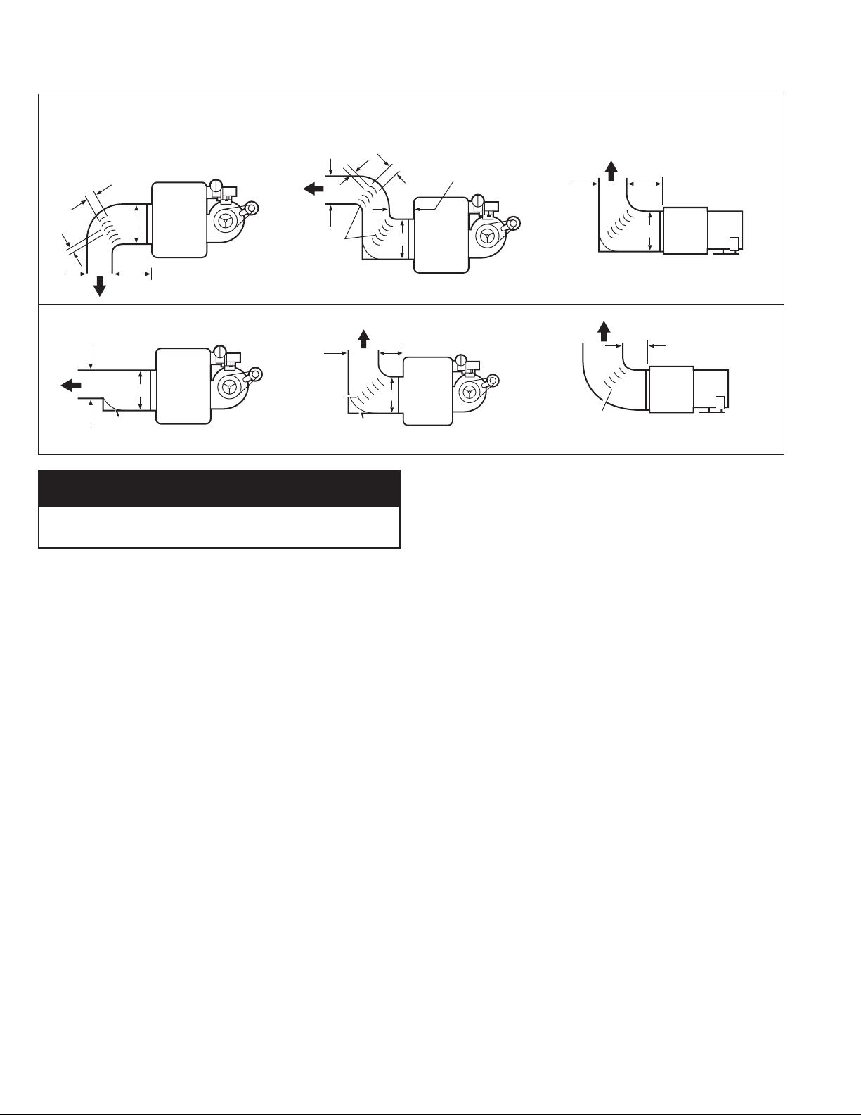
INSTALLATION WITH DUCTWORK
A
BAFFLE
B
12"
MIN.
A
B
BAFFLE
TUR NING
VANES
12" MIN.
B
3" MAX .
TUR NING
VANES
3" MIN.
A
A
3" MIN.
12"
MIN.
3" MAX.
TUR NING
VANES
12"
B
BAFFLE
A
B
12"
MIN.
12"
MIN.
TUR NING
VA NES
Figure 18.1- Typical Duct & Airflow Installation
Recommended Installations
Dimension “B” Should Never
Be Less than 1/2 of “A”
CBA
SIDE VIEW SIDE VIEW
SIDE VIEW SIDE VIEW TOP VIEW
IMPOR T ANT
Do not attempt to attach ductwork of any kind to propeller
models.
When installing the heater, always follow good duct design
practices for even distribution of the air across the heat
exchanger. Recommended layouts are shown in Figure 18.1.
When installing blower units with ductwork the following must
be done.
1. Provide uniform air distribution over the heat exchanger.
Use turning vanes where required (see Figure 18.1).
2. Provide removable access panels in the ductwork on the
downstream side of the unit heater. These openings should
be large enough to view smoke or reflect light inside the
casing to indicate leaks in the heat exchanger and to check
for hot spots on exchanger due to poor air distribution or lack
of sufficient air.
3. If ductwork is connected to the rear of the unit use Modine
blower enclosure kit or if using field designed enclosure
maintain dimensions of blower enclosure as shown on
page 27.
Additional Requirements for Installation of Blower
Models (model BTC)
Determining Blower Speed
The drive assembly and motor on gas-fired blower unit heaters
below 3 HP are are factory assembled, motors 3 HP and above
ship loose to prevent shipping damage. The adjustable motor
sheave has been pre-set to permit operation of this unit under
average conditions of air flow and without any external static
pressure. The motor sheave should be adjusted as required
when the unit is to be operated at other than average air flows
and/or with external static pressures. Adjustment must always
be within the performance range shown on page 24 and the
temperature rise range shown on the unit’s rating plate.
To determine the proper blower speed and motor sheave turns
18
TOP VIEW
FED
open, the conditions under which the unit is to operate must be
known. If the blower unit is to be used without duct work or
filters, the only criteria for determining the motor sheave turns
open and blower speed is the amount of air to be delivered. The
performance tables for blower models are shown on page 21.
As an example, a model BTC310 unit, operating with no
external static pressure, that is, no duct work, filters, etc., and is
to deliver an air volume of 6674 cfm (cfm = cubic feet of air per
minute) requires that the unit be supplied with a 5 hp motor, a
-260 drive, and the drive sheave must be set at 3.0 turns open
to achieve a blower speed of 809 rpm (see performance table
for units with or without blower enclosure, page 21). See
“Blower Adjustments” on page 19 for setting of drive pulley turns
open.
If a blower unit is to be used with ductwork or filters, etc., the
total external static pressure under which the unit is to operate,
and the required air flow must be known before the unit can be
properly adjusted.
If Modine filters are used, the expected pressure loss through
the filters is included in the performance data on page 21. If
filters or ductwork are to be used with the unit, and they are not
supplied by Modine, the design engineer or installing contractor
must determine the pressure loss for the externally added
devices or ductwork to arrive at the total external static pressure
under which the unit is to operate.
Once the total static pressure and the required air flow are
known, the operating speed of the blower can be determined
and the correct motor sheave adjustments made. As an
example, a model BTC310 is to be used with a Modine supplied
blower enclosure and Modine supplied filters attached to
ductwork. The unit is to move 6674 cfm of air flow against an
external static pressure of 0.2" W.C. Also, 0.1" W.C. must be
added for the filter pressure drop for a total of 0.3" W.C. total
pressure drop. Entering the performance table on page 21 for a
BTC310, at 6674 cfm and 0.3" W.C. static pressure, it is seen
that the unit will require a 5 hp motor using a -260 drive, and
the motor sheave should be set at 2.0 turns open to achieve a
blower speed of 866 rpm. This example differs from similar
conditions in paragraph 2 by the number of turns open and a
higher rpm, which is needed to overcome the added external
static pressure from the filters.
6-563.9
Page 19
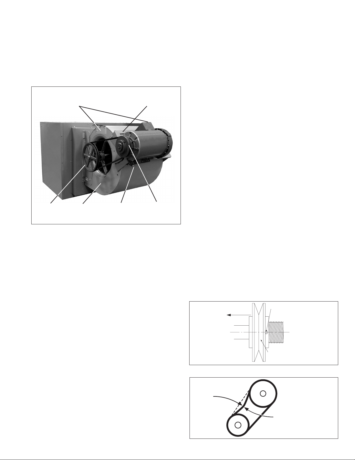
TOWARD MOTOR
SET SC REW
AD JUSTABLE HALF
OF SHEAVE
3/4" DEFLECTION
WITH 5 LBS. FORC
INSTALLATION
To Install
1. Remove and discard the motor tie down strap and the
shipping block beneath the motor adjustment screw (not used
on all models.)
2. For 3 and 5 HP motors, affix sheave to the motor shaft and
install motor on the motor mounting bracket. Install belt on
blower and motor sheaves.
Figure 19.1 - Blower Model
MOUNTING BRACKETS ON BLOWER
BLOWER
SHEAVE
ASSEMBLY
BLOWER
HOUSING
ADJUSTMENT
3. Adjust motor adjusting screw for a belt deflection of
approximately 3/4" with 5 pounds of force applied midway
between the sheaves (refer to Figure 19.3). Since the belt
tension will decrease dramatically after an initial run-in period,
it is necessary to periodically re-check the tension. Excessive
tension will cause bearing wear and noise.
4. The blower bearings are lubricated for life; however, before
initial unit operation the blower shaft should be lubricated at
the bearings with SAE 20 oil. This will reduce initial friction
and start the plastic lubricant flowing.
5. Make electrical connections according to the wiring diagram.
6. Check rotation of the blower. Motor should be in clockwise
rotation when facing motor pulley. If rotation is incorrect,
correction should be made by interchanging wiring within the
motor. See wiring diagram on the motor.
7. The actual current draw of the motor should be determined.
Under no condition should the current draw exceed that
shown on the motor rating plate.
8. It is the installer’s responsibility to adjust the motor sheave
to provide the specified blower performance as listed on
page 21 for blower settings different from the factory set
performance. The drive number on the unit may be identified
by referring to the Power Code number on the serial plate of
the unit (see page 31 for model number nomenclature) and
matching that number with those shown on page 20. From
the listing, the drive number can be determined.
MOTOR MOUNTING
MOTOR
SCREW
BRACKET
ADJUSTABLE
MOTOR SHEAVE
Blower Adjustments
Following electrical connections, check blower rotation to assure
blow-through heating. If necessary, interchange wiring to
reverse blower rotation. Start fan motor and check blower
sheave RPM with a hand-held or strobe-type tachometer. RPM
should check out with the speeds listed in Performance Data
shown on page 21. A single-speed motor with an adjustable
motor sheave is supplied with these units. If blower fan speed
changes are required, adjust motor sheave as follows:
NOTE: Do not fire unit until blower adjustment has been
made or unit may cycle on limit (overheat) control.
1. Shut-off power before making blower speed
adjustments. Refer to “Determining Blower Speed” on
page 18 and to “Performance Data” on page 21 to
determine proper blower RPM.
2. Loosen belt and take belt off of motor sheave.
3. Loosen set screw on outer side of adjustable motor sheave
(see Figure 19.2).
4. To reduce the speed of the blower, turn outer side of motor
sheave counterclockwise.
5. To increase the speed of the blower, turn outer side of motor
sheave clockwise.
6. Retighten motor sheave set screw, replace belt and
retighten motor base. Adjust motor adjusting screw such that
there is 3/4" belt deflection when pressed with 5 pounds of
force midway between the blower and motor sheaves
(see Figure 19.3). Since the belt tension will decrease
dramatically after an initial run-in period, it is necessary to
periodically re-check the tension to assure continual proper
belt adjustment.
7. Check to make certain motor sheave and blower sheave are
aligned. Re-align if necessary.
8. Re-check blower speed after adjustment.
9. Check motor amps. Do not exceed amps shown on motor
nameplate. Slow blower if necessary.
10. Check air temperature rise across unit. Check temperature
rise against values shown in Performance Tables on page 21
to assure actual desired air flow is being achieved.
11. If adjustments are required, recheck motor amps after final
blower speed adjustment.
Figure 19.2 - Motor Sheave Adjustment
Figure 19.3 - Belt Tension Adjustment
6-563.9
19
Page 20
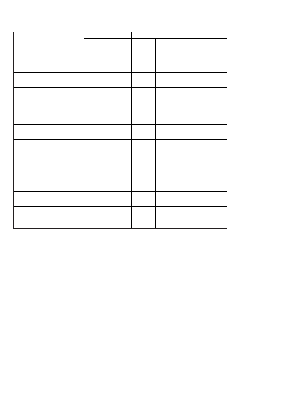
BLOWER PERFORMANCE DATA - MODEL BTC
Table 20.1 - Power Code Description - Blower Model BTC -
Power
Code
02 115/230 1 1 270 1-1/2 261 1-1/2 261
08 208-230/460 3 1 269 2 268 3 260
11 575 3 1 269 2 268 3 260
13 115/230 1 1-1/2 270 1-1/2 263 1-1/2 263
19 208-230/460 3 1-1/2 269 3 260 5 260
22 575 3 1-1/2 269 3 260 5 260
24 115/230 1 1 272 1-1/2 266 1-1/2 266
30 208-230/460 3 2 269 5 260 1-1/2 262
33 575 3 2 269 5 260 1-1/2 262
35 115/230 1 1-1/2 272 - - - -
41 208-230/460 3 3 271 1-1/2 262 2 262
44 575 3 3 271 1-1/2 262 2 262
46 115/230 1 1 274 - - - -
52 208-230/460 3 1 273 2 262 3 278
55 575 3 1 273 2 262 3 278
57 115/230 1 1 277 - - - -
63 208-230/460 3 1-1/2 273 3 278 1-1/2 264
66 575 3 1-1/2 273 3 278 1-1/2 264
74 208-230/460 3 2 273 1-1/2 264 2 264
77 575 3 2 273 1-1/2 264 2 264
80 575 3 1 275 2 264 3 265
83 575 3 1 276 1-1/2 267 1-1/2 267
84 208-230/460 3 1 275 2 264 3 265
85 208-230/460 3 1 276 1-1/2 267 1-1/2 267
For selection of correct power code, refer to the tables on page 21.
Voltage Phase
BTC215 BTC260 BTC310
HP Drive HP Drive HP Drive
Table 20.2 - Filter Static Pressure Drop
BTC215 BTC260 BTC310
Filter Static ("W.C.) 0.1 0.1 0.1
Calculatedat55°FATR,forblowerunitswithenclosureandlter,addlterstatic
to external static pressure
.
20
6-563.9
Page 21
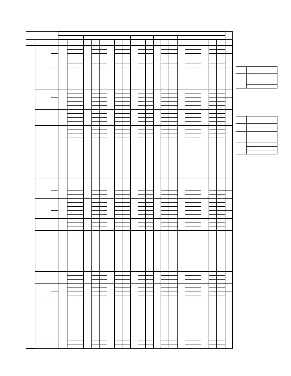
BLOWER PERFORMANCE DATA - MODEL BTC
Table 21.1 - Blower Model BTC215-310 -
Model
ATR CFM HP RPM Drive Turns RPM Drive Turns RPM Drive Turns RPM Drive Turns RPM Drive Turns RPM Drive Turns RPM Drive Turns HP
Size
40 4628
45 4114
50 3703
55 3366
215
60 3086 1 422
65 2848 1 392
70 2645 1 368
40 5597
45 4975 3 713
50 4478
260
55 4071
60 3731 1-1/2 543
65 3444 1-1/2 503
70 3198 1-1/2 469
40 6674 5 809 260 3.0 827 260 3.0 847 2.5 2.5 866 260 2.0 886 260 1.5 906 260 1.0 922 260 0.5 5
45 5932
50 5339 3 652
55 4854
310
60 4449
65 4107
70 3813 1-1/2 471
2
3 - - - - - - - - - - 271 1.0 271 0.5 3
1-1/2
2 - - - - - - - - - - 269 2.5 269 2.0 2
1
1-1/2
1
1-1/2
3
5 - - - - 260 2.5 260 2.0 260 1.5 260 1.0 260 0.5 5
2
3
1-1/2
2
3
5 - - - - - - 260 3.5 260 3.0 260 2.5 260 2.5 5
2
3
1-1/2
2
1-1/2
2
0.0 0.1 0.2 0.3 0.4 0.5 0.58
269 5.0
273 0.5 - - - - - - - - - - - -
618
- -
273 3.0 273 1.5 273 0.5 - - - - - - - -
552
273 4.5
275 1.5 275 0.5 - - - - - - - - - -
500
- - - - - - - - 269 4.5 269 3.5 269 3.0
- - - - - - 273 1.0 273 0.0 - - - -
275 3.5
276 1.0 - - - - - - - - - - - -
457
- - - - - - - - - - 269 4.5 269 3.0
- - - - - - - - - - 273 0.0 - -
- -
- - - - 273 4.5 273 3.0 273 2.0 273 0.5 - -
275 5.0 275 3.0 275 1.5 275 0.0 - - - - - -
276 2.5 276 0.5 - - - - - - - - - -
- -
- - 275 4.0 275 2.5 275 1.0 - - - - - -
276 4.0 276 1.5 - - - - - - - - - -
- -
- - - - - - 273 4.5 273 3.0 273 1.5 273 0.5
- - 275 5.0 275 3.0 275 1.5 275 0.0 - - - -
276 5.0 276 2.5 276 0.5 - - - - - - - -
260 3.5
797
278 0.0 - - - - - - - - - - - -
- -
278 2.5 278 1.5 278 1.0 278 0.5 - - - - - -
- -
646
264 1.5 264 0.5 - - - - - - - - - -
- - - - - - - - - - 260 4.0 260 3.5
- - - - - - - - - - 278 0.5 278 0.0
- -
267 0.0 - - - - - - - - - - - -
590
- - - - - - - - - - 268 5.0 268 4.5
- - - - - - - - 262 2.5 262 1.5 262 1.0
- -
267 1.5 267 0.5 - - - - - - - - - -
- -
267 3.0 267 1.5 267 0.5 - - - - - - - -
- -
267 4.5 267 3.0 267 1.5 267 0.0 - - - - - -
- -
278 2.0 278 1.5 278 1.0 278 0.5 - - - - - -
722
- -
265 1.0 265 0.5 - - - - - - - - - -
- -
264 3.0 264 2.0 264 1.5 264 0.5 - - - - - -
595
- - - - - - - - - - 260 5.0 260 4.5
- - - - - - - - - - 278 2.0 278 1.5
264 4.5
267 1.5 267 0.5 - - - - - - - - - -
547
- - - - - - 262 4.5 262 3.5 262 3.0 262 2.5
- - - - - - 264 1.5 264 1.0 264 0.0 - -
- -
506
267 3.0 267 2.0 267 0.5 - - - - - - - -
- - - - - - - - - - - - 262 3.0
- - - - - - - - - - - - 264 0.0
- -
267 4.0 267 3.0 267 1.5 267 0.5 - - - - - -
647
586
534
497
463
439
419
821
739
674
622
576
540
507
743
677
621
575
537
507
269 4.0
- -
273 3.5
275 2.0
- -
- -
- -
260 3.0
260 5.0
- -
262 5.0
- -
- -
- -
260 5.0
- -
262 5.0
264 3.5
- -
- -
External Static Pressure (“W.C.)
676
617
569
534
504
481
464
843
764
702
653
609
575
544
765
701
648
605
569
541
269 3.5
269 5.0
273 2.0
275 0.5
- -
- -
- -
- -
260 4.5
- -
262 4.0
- -
- -
- -
260 4.5
- -
262 4.0
264 2.5
- -
- -
269 2.5
703
269 4.0
648
602
570
541
273 4.0 273 2.5 273 1.5 273 0.5
521
506
866
260 3.5
789
268 5.0
729
262 3.0
682
262 4.5
641
609
580
788
260 5.0
726
262 3.5
676
635
601
575
- -
- -
- -
- -
- -
- -
- -
- -
- -
- -
- -
- -
730
677
634
604
578
559
546
888
813
755
710
671
641
614
810
751
703
664
632
608
269 2.0
269 3.5
- -
- -
- -
- -
- -
- -
260 3.0
268 4.5
- -
262 3.5
262 4.5
262 5.0
- -
260 4.5
262 2.5
- -
262 4.5
- -
757
706
665
636
612
596
584
910
837
781
738
701
672
647
833
776
729
692
662
640
- -
- -
- -
- -
269 5.0
- -
- -
- -
260 2.5
- -
- -
262 2.5
262 3.5
262 4.0
- -
260 4.0
- -
- -
262 3.5
262 4.5
777
727
690
685
640
624
614
927
856
801
760
724
697
673
850
795
750
714
686
663
- -
- -
- -
- -
269 4.5
269 5.0
269 5.0
- -
260 2.0
- -
- -
262 2.0
262 3.0
262 3.5
- -
260 3.5
- -
- -
- -
262 3.5
Table 21.2 -
2
Alternate Drives
for 115/230V 1 Ph,
1 HP Motors
1-1/2
1 HP Drive
Model
Listed
BTC215
269 = 270
273 = 272
275 = 274
276 = 277
1
1-1/2
1
Table 21.3 Alternate Drives
1-1/2- - 273 4.5 273 3.5 273 2.0 273 1.0 - - - -
for 115/230V 1 Ph,
1-1/2 HP Motors
1
1
1
3
3
2262 4.0 262 3.5 262 2.5 262 2.0 262 2.0 - - - -
3
1-1/2264 3.0 264 2.0 264 1.0 264 0.0 - - - - - -
2
1-1/2264 4.5 264 3.5 264 2.5 264 1.5 264 0.5 - - - -
1-1/2- - 264 5.0 264 3.5 264 2.5 264 1.5 264 0.5 - -
1-1/2- - - - 264 4.5 264 3.5 264 2.5 264 1.5 264 0.5
3
3278 4.0 278 3.5 278 2.5 278 2.0 278 1.5 278 0.5 278 0.0
2
3
1-1/2
2
1-1/2- - 264 5.0 264 4.0 264 3.0 264 2.0 264 1.0 - -
2
1-1/2- - - - 264 4.5 264 3.5 264 2.5 264 1.5 264 1.0
1-1/2 HP
Model
Drive Listed
269 = 270
BTC215
273 = 272
262 = 261
BTC260
264 = 263
267 = 266
262 = 261
BTC310
264 = 263
267 = 266
➀Outputs shown are for
elevations up to 2000'.
For elevations over
2000’, output needs to
be reduced 4% for
each 1000' above sea
level. (Does not apply in
Canada - see rating
plate).
➀Sheave turns open
are approximate.
For proper operation,
check blower rpm.
➀ For 115/230V (1 HP and
1-1/2 HP) selections, see
Tables 21.2 & 3 for the
corrected Drive Number.
1 HP Drive
for 115/230V
1-1/2 HP Drive
for 115/230V
6-563.9
21
Page 22

INSTALLATION - OPERATION
OPERATION
Prior to Operation
IMPORTANT
Start-up and adjustment procedures must be performed by
a qualified service agency.
Although this unit has been assembled and fire-tested at the
factory, the following pre-operational procedures should be
performed to assure proper on-site operation.
1. Turn off power to the unit at the disconnect switch. Check
that fuses or circuit breakers are in place and sized
correctly. Turn all hand gas valves to the OFF position.
2. Remove the side control access panel.
3. Check that the supply voltage matches the unit supply
voltage listed on the Model Identification plate. Verify that all
wiring is secure and properly protected. Trace circuits to
insure that the unit has been wired according to the wiring
diagram. If installed at altitudes above 2,000' and the high
altitude kit includes a combustion air proving switch, replace
the switch in the unit with the switch provided in the kit.
Take care to ensure that the tubing and electrical
connections are securely fastened.
4. Check to insure that the venting system is installed correctly
and is free from obstructions. Before starting the unit, use
the following steps to verify that the venting system is
adequately sized:
a. Inspect the venting system for proper size and horizontal
pitch, as required in these instructions. Determine that
there is no blockage or restriction, leakage, or other
deficiencies, which could cause an unsafe condition.
b. Follow the lighting instructions. Place the appliance being
inspected in operation. Adjust thermostat so that the
appliance will operate continuously.
c. If the vent pressure switch does not close during any of
the above tests, the venting system must be corrected.
5. Check to see that there are no obstructions to the intake
and discharge of the unit.
6. Check fan clearance. Fan should not contact casing when
spun by hand.
7. Perform a visual inspection of the unit to make sure no
damage has occurred during installation. Check to ensure
all fasteners are in place and the burner openings are
properly aligned with the heat exchanger tubes and that the
gas orifices are centered in the burner inspirator tube opening.
8. Check to make sure that all filters are in place and that
they are installed properly according to direction of air flow
(if applicable).
9. Check that all horizontal deflector blades are open a
minimum of 30° as measured from vertical.
10. Turn on power to the unit at the disconnect switch. Verify
that the green light on the unit junction box is on, which
confirms power is on.
11. With the gas turned off, check the thermostat, ignition
control, gas valve, and supply fan motor for electrical
operation by creating a call for heat from the thermostat.
If these do not function, recheck the wiring diagram. Verify
that the amber light on the unit junction box is on, confirming
that there is a call for heat.
12. For blower units, check the blower speed (rpm). Refer to
“Blower Adjustments” for modification.
13. Check the motor speed (rpm).
14. Check the motor voltage.
15. Check the motor amp draw to make sure it does not exceed
the motor nameplate rating.
16. Recheck the gas supply pressure at the field installed
manual shut-off valve. The minimum inlet pressure should
be 6" W.C. on natural gas and 11" W.C. on propane gas.
The maximum inlet pressure for either gas is 14" W.C. If
inlet pressure exceeds 14" W.C., a gas pressure regulator
must be added upstream of the combination gas valve.
17. Open the field installed manual gas shut-off valve.
18. Place the manual main gas valve on the combination gas
valve in the “On” position. Call for heat with the thermostat.
19. Check to make sure that the main gas valve opens. Check
the manifold gas pressure (see “Main Gas Adjustment”)
while the supply fan is operating. Verify that the blue light on
the unit junction box is on, confirming that the main gas
valve is open.
20. Check to insure that gas controls sequence properly (see
“Control Operating Sequence”). If unfamiliar with the unit’s
controls (i.e. combination gas control), refer to the control
manufacturer’s literature supplied with the unit.
21. Once proper operation of the unit has been verified,
remove any jumper wires that were required for testing.
22. Replace the side control access panel.
23. If installed at altitudes above 2,000', affix label included with
high altitude kit and fill in all fields with a permanent marker.
Main Gas Adjustment
The gas pressure regulator (integral to the combination gas
control) is adjusted at the factory for average gas conditions. It
is important that gas be supplied to the unit heater in accordance
with the input rating on the serial plate. Actual input should be
checked and necessary adjustments made after the unit heater
is installed. Over-firing, a result of too high an input, reduces
the life of the appliance and increases maintenance. Under no
circumstances should the input exceed that shown on the serial
plate.
Measuring the manifold pressure is done at the outlet pressure
tap of the gas valve.
To Adjust the Manifold Pressure
1. Move the field installed manual shut-off valve to the “OFF”
position.
2. Remove the 1/8" pipe plug from the outlet pressure tap on
the gas valve and attach a water manometer of “U” tube
type which is at least 12" high.
3. Move the field installed manual gas shut-off valve to the
“ON” position.
4. Create a call for heat from the thermostat.
5. Refer to Table 14.1 to determine the correct manifold
pressure for the gas type of the unit. Pressures at 0-2,000'
elevation are 3.5" W.C. for natural gas, 10" W.C. for propane
gas, for elevations above 2,000' refer to the instructions in
“Gas Connections - High Altitude Accessory Kit” on page 12.
Adjust the main gas pressure regulator spring to achieve the
proper manifold pressure (for location, see the combination
gas control literature supplied with unit).
6. After adjustment, move the field installed manual shut-off
valve to the “OFF” position and replace the 1/8" pipe plug.
7. After the plug is in place, move the field installed manual
shut-off valve to the “ON” position and recheck pipe plugs
for gas leaks with soap solution.
CONTROL OPERATING SEQUENCE
Upon a call for heat from the thermostat, power is supplied to
the power exhauster motor. The unit will go through a purge
period and then the direct spark igniter will be energized. At the
same time, the main valve in the combination control valve will
open to allow gas to flow to the burners. If the fan motor has not
already started it will start shortly. If a flame is not sensed within
7 seconds for any reason the main valve will close and there
will be a short purge period before ignition is tried again. If the
flame is not sensed after 4 tries there will be at least a 1 hour
wait before ignition is tried again.
22
6-563.9
Page 23
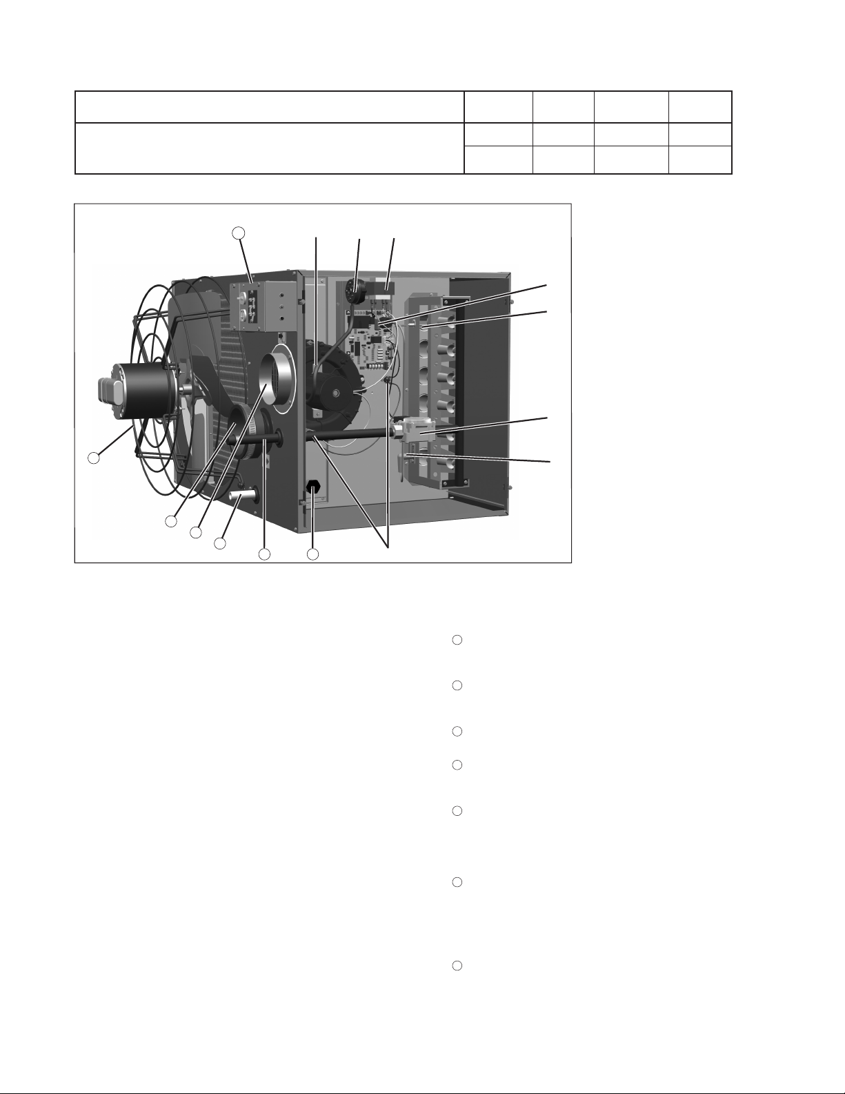
UNIT COMPONENTS
Table 23.1 - Control Options
Code No. Voltage Voltage Gas
Single-Stage, Direct Spark Ignition, 100% Shut-Off with Continuous Retry 11 115V 24V Natural
Utilizes a single-stage combination gas control with ignition control.
Gas is lit with a direct spark igniter on call for heat. 21 115V 24V Propane
Control Description
Control Service Thermostat Type of
Figure 23.1 - Factory Mounted Standard Features
o Single Stage Gas Valve
16
15
14
13
12
11 10
j
k
l
r
j Power Exhauster
All units are supplied with a round vent pipe and
combustion air inlet pipe connections.
k Pressure Switch
An automatic reset vent pressure switch is supplied on all
units and is designed to prevent operation of the main
burner in the event there is restricted venting of flue
products. This restriction may occur due to an improper vent
diameter, long vent runs, un-approved vent terminal, high
winds, high negative pressure within space, etc. After the
cause of the restriction has been corrected, the pressure
switch will reset automatically.
l Control Step Down Transformer
The control step down transformer is located in the electrical
junction box. The transformer is used to step the voltage
down from 115V to 24V for the gas controls, fan delay relay,
field supplied motor starter, etc. An additional field installed
transformer is required if the supply voltage is 208V, 230V,
460V, or 575V. To determine the control transformer
supplied as well as any required accessory transformers,
refer to Tables 17.1-17.2.
m Integrated Direct Spark Control Board
The integrated direct spark ignition control combines all
furnace control functions. The integrated board provides
digital control of the air mover, inducer, ignition, gas valve
and flame sensing as well as monitoring the safety circuit at
all times. The board includes LED diagnostics for trouble
shooting and a fused power supply. Ignition control is 100%
shut-off with continuous retry.
n Flame Sensor
Remote flame sensor verifies ignition of all burners,
monitors the flame signal and communicates with the
integrated circuit board.
m
n
o
q
10Condensate Drain Overflow Switch
Shuts down gas controls if condensate is not properly
draining from the unit.
11
Gas Pipe Connection
Easy access to factory installed gas pipe connection
stubbed to outside of unit casing.
12
Condensate Drain Connection
Easy access to factory installed condensate drain pipe
connection stubbed to outside of unit casing.
13
Combustion Air Inlet Pipe Connection
Simple connection for combustion air inlet piping.
14
Vent Pipe Connection
Rubber exhaust coupling with clamp for easy connection of
PVC vent system.
15
Fan Guard
Propeller units may be equipped with an optional (standard
on size 110 and smaller) finger proof fan guard for added
protection. If ordered, the finger proof fan guard is installed at
the factory in place of the standard fan guard.
16
Contractor Convenience Package
External junction box features simple connection of supply
power wiring internally, thermostat wiring to terminals
externally, an On/Off switch, a single 115V outlet for
connection of an external condensate pump, and status
indicator lights to display the operational state of the unit.
17
Horizontal Air Deflector Blades (not shown in Figure 23.1)
Factory mounted on the discharge of the unit, the blades can
be adjusted to provide horizontal (up and down) delivery
control of the heated air. Vertical deflector blades are
available as a field installed accessory.
6-563.9
The main gas valve is factory
installed on the unit heater gas
train. The main gas valve provides
regulator, main gas, and manual
shutoff functions. The valve is
redundant and provides 100% shut
off. Natural gas is Control Code 11,
propane gas is Control Code 21.
p Flame Roll Out Switch (size 110
and smaller only) (hidden)
Flame roll out switches are mounted
near the burners and will shut off
the gas supply in the event of an
unsafe flame roll out condition.
q Direct Spark Igniter
Provides spark for direct ignition of
the burners.
r High Limit Switches
One limit control is mounted in the
air stream and will shut off the gas
supply in the event of overheating.
The other limit control is mounted
on the power exhauster housing
and will shut off the gas supply in
the event of overheating flue gas
temperatures.
23
Page 24
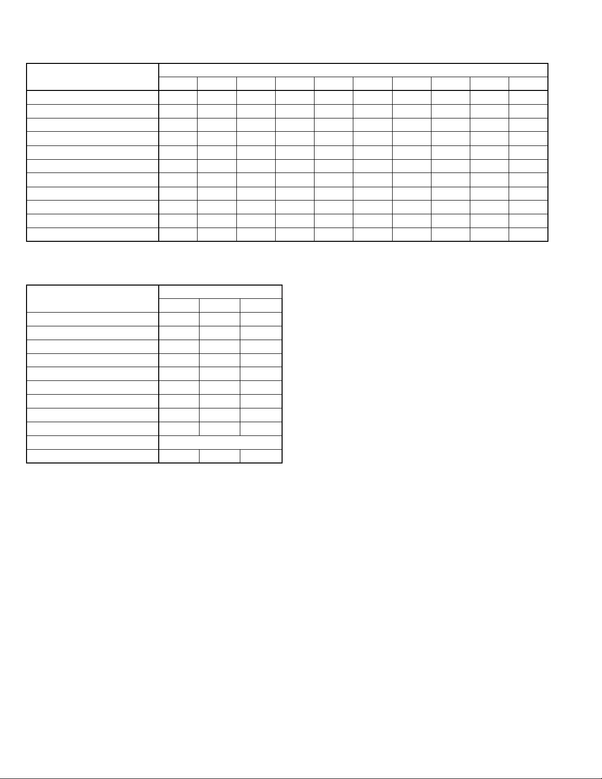
GENERAL PERFORMANCE DATA - MODELS PTC & BTC
Table 24.1 - Propeller Unit Heater Model PTC General Performance Data
Model PTC Sizes
55 65 85 110 135 156 180 215 260 310
Btu/Hr Input ➀ 55,000 65,000 85,000 110,000 135,000 155,000 180,000 215,000 260,000 310,000
Btu/Hr Output ➀ 51,150 61,100 79,900 102,300 125,550 145,080 169,200 202,100 249,600 291,400
Condensate Production (Gal./Hr.) 0.3 0.4 0.5 0.7 1.0 1.1 1.3 1.6 1.9 2.3
Entering Airflow (CFM) @ 70°F ➁ 1097 1141 1650 1750 2160 2600 3020 3865 4585 5400
Outlet Velocity (FPM) ➁ 618 650 619 668 719 862 676 699 831 765
Air Temp. Rise (°F) 43 49 44 54 54 51 51 48 49 49
Max. Mounting Height (Ft.) ➁ 12 12 13 13 14 18 15 17 20 19
Heat Throw (Ft.) @ Max. Mtg Ht 43 43 48 46 51 62 53 60 70 67
Motor Type ➂ PSC PSC PSC PSC PSC PSC PSC PSC PSC PSC
Motor HP 1/8 1/8 1/8 1/3 1/3 1/3 1/3 1/2 3/4 3/4
Motor RPM 1440 1440 1550 1075 1075 1075 1075 1075 1125 1125
Table 24.2 - Blower Unit Heater Model BTC
General Performance Data
Model BTC Sizes
215 260 310
Btu/Hr Input ➀ 215,000 260,000 310,000
Btu/Hr Output ➀ 204,250 252,200 294,500
Condensate Production (Gal./Hr.) 1.6 1.9 2.3
Entering Airflow Range (CFM) 2645-4628 3198-5597 3813-6674
Outlet Velocity (FPM) ➁ 497-826 601-999 559-930
Air Temp. Rise (°F) 40-70 40-70 40-70
Max. Mounting Height (Ft.) ➁ 9-22 11-26 11-26
Heat Throw (Ft.) @ Max. Mtg Ht 33-77 40-94 39-91
Motor Type ➂ TE TE TE
Motor HP See Table 20.1
Motor RPM 1725 1725 1725
j Ratings shown are for elevations up to 2,000'. For elevations above 2,000',
ratings should be reduced at the rate of 4% for each 1,000' above sea level.
(In Canada see rating plate.) Reduction of ratings requires use of a high
altitude kit.
kDatatakenat65°Fambientandunitredatfull-ratedinput.Mountingheight
asmeasuredfrombottomofunit,andwithoutdeectorhoods.
lAll motors used are produced, rated and tested by reputable manufacturers in
accordance with NEMA standards and carry the standard warranty of both the
motor manufacturer and Modine. All motors are totally enclosed and all single
phase motors have built-in thermal overload protection.
24
6-563.9
Page 25
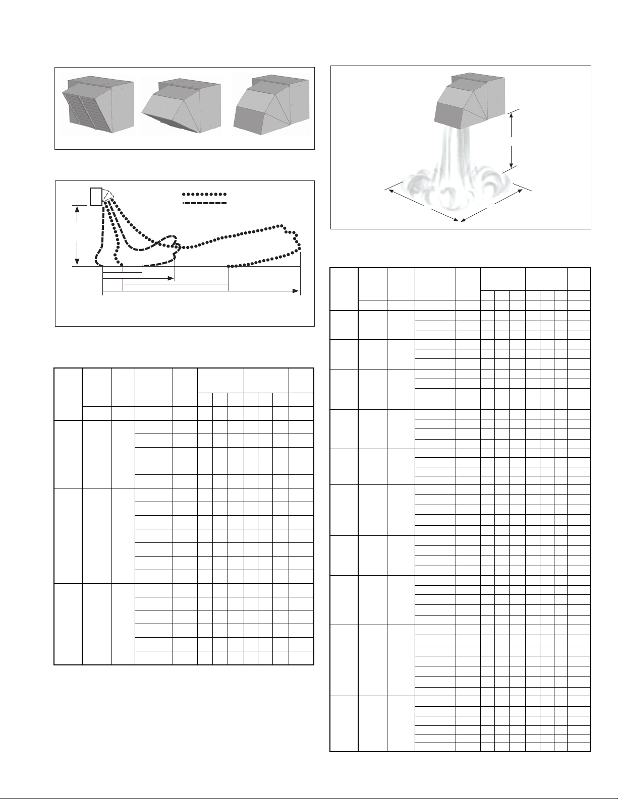
MOUNTING
HEIGHT
X
Y
Y
Z
Z
X
60 DO WNT URN
30 DO WNTU RN
Note:
X = Feet from H eater to Start of Floor C overage
Y = Feet to E nd of Floor C overage
Z = Feet to E nd of Throw
60
30
30 DOWNTU RN
60 DOWNTU RN
PERFORMANCE DATA - DEFLECTOR HOODS
Figure 25.1 - 30°, 60°, & 90° Deflector Hoods
30° HOOD 60° HOOD 90° HOOD
Figure 25.2 -
Table 25.1 - Deflector Hood General Performance
Data - Model BTC
Airflow
Model
Size
(CFM) (°F) (ft) (°) (ft) (ft) (ft) (ft) (ft) (ft) (ft)
215 3366 55
260 4071 55
310 4854 55
Note: Refer to Figures 25.2 and 25.3.
30° & 60° Hood Throw/Floor Coverage
Temp
Rise
Mounting
Height
8 59 14 31 42 27 32 44 22
10 50 13 29 40 36 30 41 20
12 40 11 27 37 40 27 37 18
14 27 9 24 33 35 22 31 17
15 17 7 21 30 28 18 25 16
8 65 18 38 52 34 40 55 29
10 58 17 37 50 48 39 53 26
12 51 15 35 49 59 36 50 24
14 42 14 33 46 64 33 46 22
16 33 12 30 42 61 29 40 21
18 18 9 26 37 42 23 32 19
19 2 6 20 30 52 23 32 19
8 64 17 37 51 33 39 54 28
10 57 16 36 49 47 37 51 21
12 50 15 34 47 56 35 48 16
14 41 13 32 44 61 32 44 13
16 30 11 29 41 56 27 38 11
18 14 8 23 33 30 20 28 9
30° Hood 60° Hood
Blade
Angle
X Y Z X Y Z S
90°
Hood
Figure 25.3 - 90° Hood Throw/Floor Coverage
H
S
S
Table 25.2 - Deflector Hood General Performance
Data - Model PTC
Airflow
Model
Size
(CFM) (°F) (ft) (°) (ft) (ft) (ft) (ft) (ft) (ft) (ft)
55 1097 43
65 1141 49
85 1650 44
110 1750 54
135 2160 53
156 2600 51
180 3020 51
215 3865 48
260 4585 49
310 5400 49
Note: Refer to Figures 25.2 and 25.3.
6-563.9
Temp
Rise
Mounting
Height
8 55 12 27 37 0 28 39 19
10 44 11 25 35 0 26 35 17
12 31 9 23 32 0 22 30 15
8 54 12 26 36 0 27 38 18
10 43 10 24 34 0 25 34 16
12 29 8 21 30 0 20 28 15
8 59 14 30 41 0 32 43 17
10 49 12 29 39 0 29 40 16
12 39 11 26 37 0 26 36 14
13 32 10 25 35 0 24 33 14
8 57 13 29 39 0 30 41 16
10 47 11 27 37 0 28 38 15
12 35 10 25 34 0 24 33 13
13 28 9 23 32 0 22 30 13
8 60 15 32 44 0 34 47 24
10 52 13 31 42 0 32 44 21
12 42 12 29 40 0 29 40 19
14 30 10 26 36 0 25 34 18
8 60 19 41 56 0 43 60 26
10 51 18 40 55 0 42 57 23
12 41 17 38 53 0 40 55 21
14 29 15 37 51 0 37 51 20
16 8 14 34 48 0 34 47 18
8 63 16 35 48 0 37 51 26
10 55 15 34 46 0 35 48 23
12 46 13 32 44 0 32 45 21
14 36 12 29 41 0 29 40 20
8 66 19 41 56 0 43 59 32
10 60 18 40 54 0 42 57 29
12 53 17 38 53 0 40 54 26
14 46 15 36 50 0 37 51 24
16 37 14 34 47 0 33 46 23
8 69 22 45 62 0 48 66 37
10 63 21 44 61 0 47 64 33
12 57 19 43 59 0 45 62 30
14 51 18 42 57 0 43 59 28
16 44 17 40 55 0 40 55 26
18 35 15 37 52 0 36 50 25
20 25 13 33 47 0 31 43 24
8 68 20 43 58 0 45 62 34
10 61 19 42 57 0 44 60 31
12 55 18 40 55 0 42 58 28
14 48 17 39 53 0 40 54 26
16 40 15 37 51 0 36 50 24
18 31 13 34 47 0 32 44 23
30° Hood 60° Hood
Blade
Angle
X Y Z X Y Z S
90°
Hood
25
Page 26
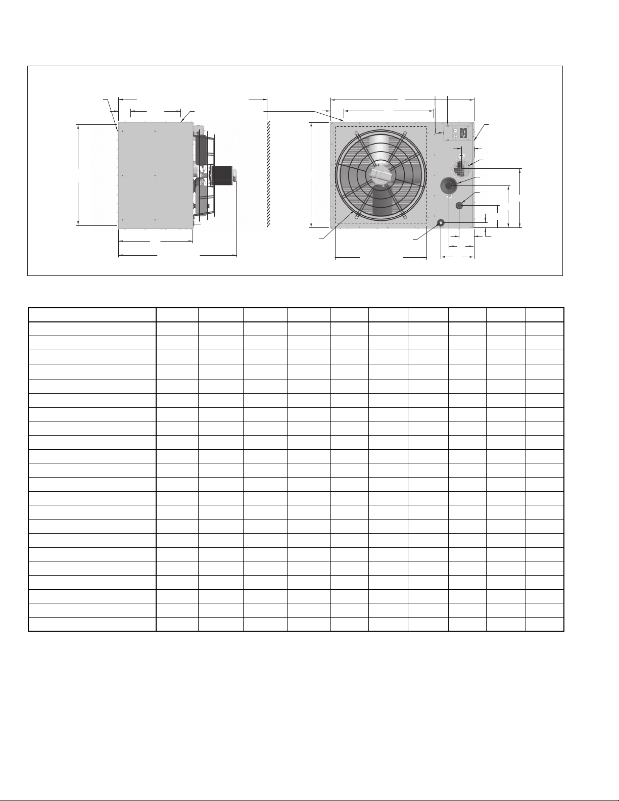
DIMENSIONAL DATA - MODEL PTC
Figure 26.1 - Dimensional Drawings - Model PTC
KNOCKOUTS FOR
SUPPLY POWER WIRING
ADJUSTABLE
LOUVERS
E
(OPENING)
Q (MINIMUM DISTANCE TO WALL)
3.56
14.90
C
R (APPROX.)
(4) 3/8"-16 MTG HOLES
B
FAN
N P
CONDENSATE DRAIN
3/4" PVC
D (OPENING)
Table 26.1 - Dimensions (inches) - PTC ➀
Models PTC 55 PTC 65 PTC 85 PTC110 PTC135 PTC156 PTC180 PTC 215 PTC260 PTC310
A 29.80 29.80 35.53 35.53 35.53 35.53 42.53 42.53 42.53 42.53
B 18.13 18.13 20.31 20.31 23.06 23.06 25.81 31.31 31.31 39.56
C 19.03 19.03 22.05 22.05 22.05 22.05 22.05 22.05 22.05 22.05
D 17.00 17.00 22.52 22.52 22.52 22.52 29.52 29.52 29.52 29.52
E 16.24 16.24 18.42 18.42 21.18 21.18 23.93 29.43 29.43 37.68
F 4.71 4.71 4.50 4.50 4.50 4.50 4.50 4.50 4.50 4.50
G 7.19 7.19 7.98 7.98 7.98 7.98 7.98 7.47 7.47 8.12
H 10.22 10.22 10.27 10.27 10.18 10.18 10.36 9.86 9.86 9.79
I 3.10 3.10 1.32 1.32 2.15 2.15 1.73 1.63 1.63 1.88
J 12.81 12.81 6.73 6.73 8.09 8.09 9.47 6.72 6.72 10.84
K 6.00 6.00 8.74 8.74 8.45 8.45 9.82 12.58 12.58 16.19
L 9.07 9.07 12.13 12.13 12.95 13.45 14.92 17.58 17.58 22.19
M 3.30 3.30 3.86 3.86 3.48 3.98 3.98 3.72 3.72 4.62
N 1.90 1.90 1.54 1.54 1.54 1.54 3.97 3.97 3.97 3.97
P 16.00 16.00 22.03 22.03 22.03 22.03 26.60 26.60 26.60 26.60
Q ➁ 40.19 40.19 45.83 45.83 45.83 45.83 45.83 45.83 46.83 46.83
R 28.19 28.19 33.83 33.83 33.83 33.83 33.83 33.83 34.83 34.83
Combustion Air Inlet Pipe 3 3 3 3 3 4 4 4 4 6
Vent Outlet Pipe 3 3 3 3 3 4 4 4 4 4
Gas Connection 1/2 1/2 1/2 1/2 1/2 1/2 1/2 3/4 3/4 3/4
Fan Diameter 14 14 18 18 20 20 22 24 24 26
Approx. Shipping Weight (lbs.) 93 103 125 128 165 165 215 265 265 310
CONDUIT ENTRANCE
A
G
H
F
ACCESS
PANEL
M
COMBUSTION
AIR INLET
VENT
OUTLET
GAS
CONN.
K
J
I
L
➀ Do not use propeller units with duct work.
➁ Dimension equals overall plus 12".
26
6-563.9
Page 27
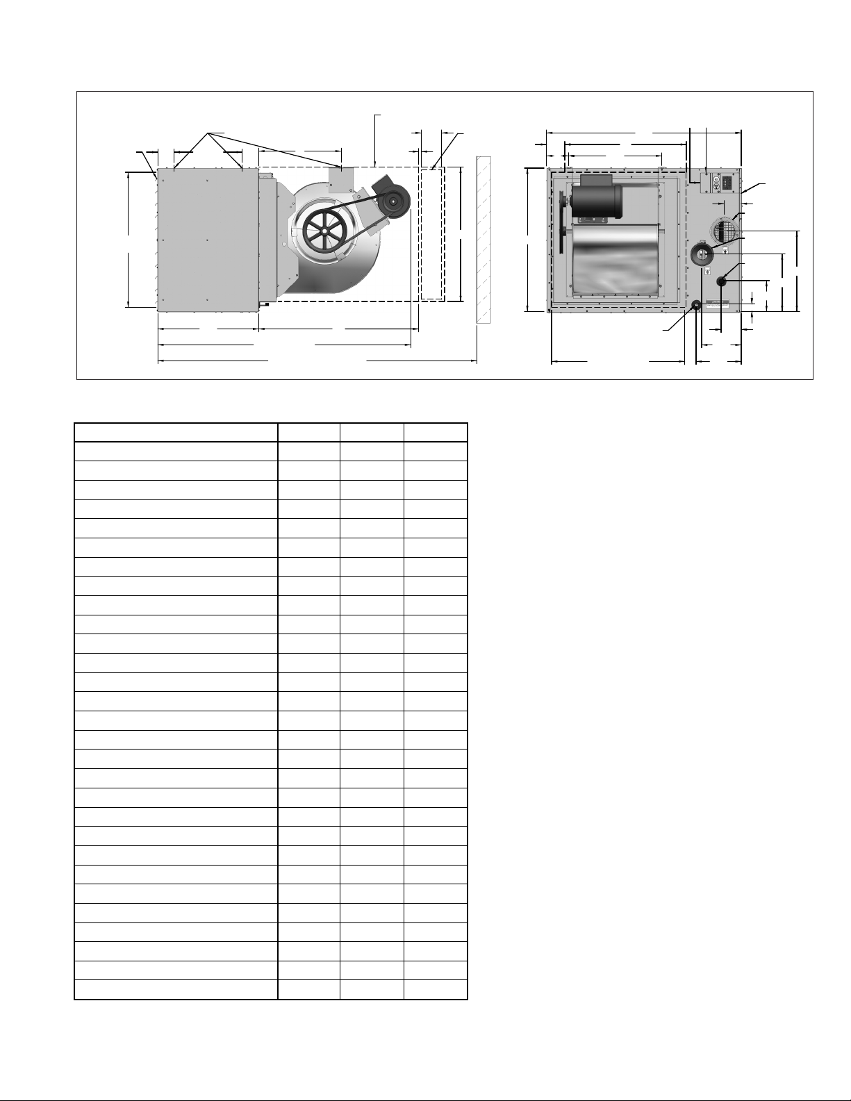
DIMENSIONAL DATA - MODEL BTC
Figure 27.1 - Dimensional Drawings - Model BTC
BLOWER ENCLOSURE
(OPTIONAL)
7/8"
ADJUSTABLE
LOUVERS
E
(OPENING)
(6) 3/8"-16 MTG HOLES
14.903.56
C
V
S
R (APPROX.)
Q (MIN DIST TO WALL)
Table 27.1 - Dimensions (inches) - BTC
Models BTC 215 BTC260 BTC310
A 42.53 42.53 42.53
B 31.31 31.31 39.56
C 22.05 22.05 22.05
D 29.52 29.52 29.52
E 29.43 29.43 37.68
F 4.50 4.50 4.50
G 7.47 7.47 8.12
H 9.86 9.86 9.79
I 1.63 1.63 1.88
J 6.72 6.72 10.84
K 12.58 12.58 16.19
L 17.58 17.58 22.19
M 3.72 3.72 4.62
N 3.97 3.97 3.97
P 26.60 26.60 26.60
Q (w/Blower Encl & Filter Rack) 79.68 79.68 79.68
Q (w/o Blower Encl & Filter Rack) 70.88 70.88 70.88
R ➀ 58.88 58.88 58.88
S 39.88 39.88 39.88
T 28.57 28.57 28.57
U 28.28 28.28 28.28
V 18.00 18.00 18.00
W 5.45 5.45 6.45
X 20.59 20.59 21.59
Combustion Air Inlet Pipe 4 4 6
Vent Outlet Pipe 4 4 4
Gas Connection 3/4 3/4 3/4
Blower 15-15 15-15 15-15
Approx. Shipping Weight (lbs.) 340 350 395
4.88
FILTER RACK
(OPTIONAL)
T x U
B
N P
W
X
CONDENSATE DRAIN
3/4" PVC
D (OPENING)
KNOCKOUTS FOR
SUPPLY POWER WIRING
CONDUIT ENTRANCE
A
G
H
M
F
F
ACCESS
ACCESS
PANEL
PANEL
COMBUSTION
COMBUSTION
AIR INLET
AIR INLET
VENT
VENT
OUTLET
OUTLET
GAS
GAS
CONN.
CONN.
I
I
L
K
J
➀ This is an approximate dimension for standard motors, allow 3" for sheave and
optional motors.
6-563.9
27
 Loading...