

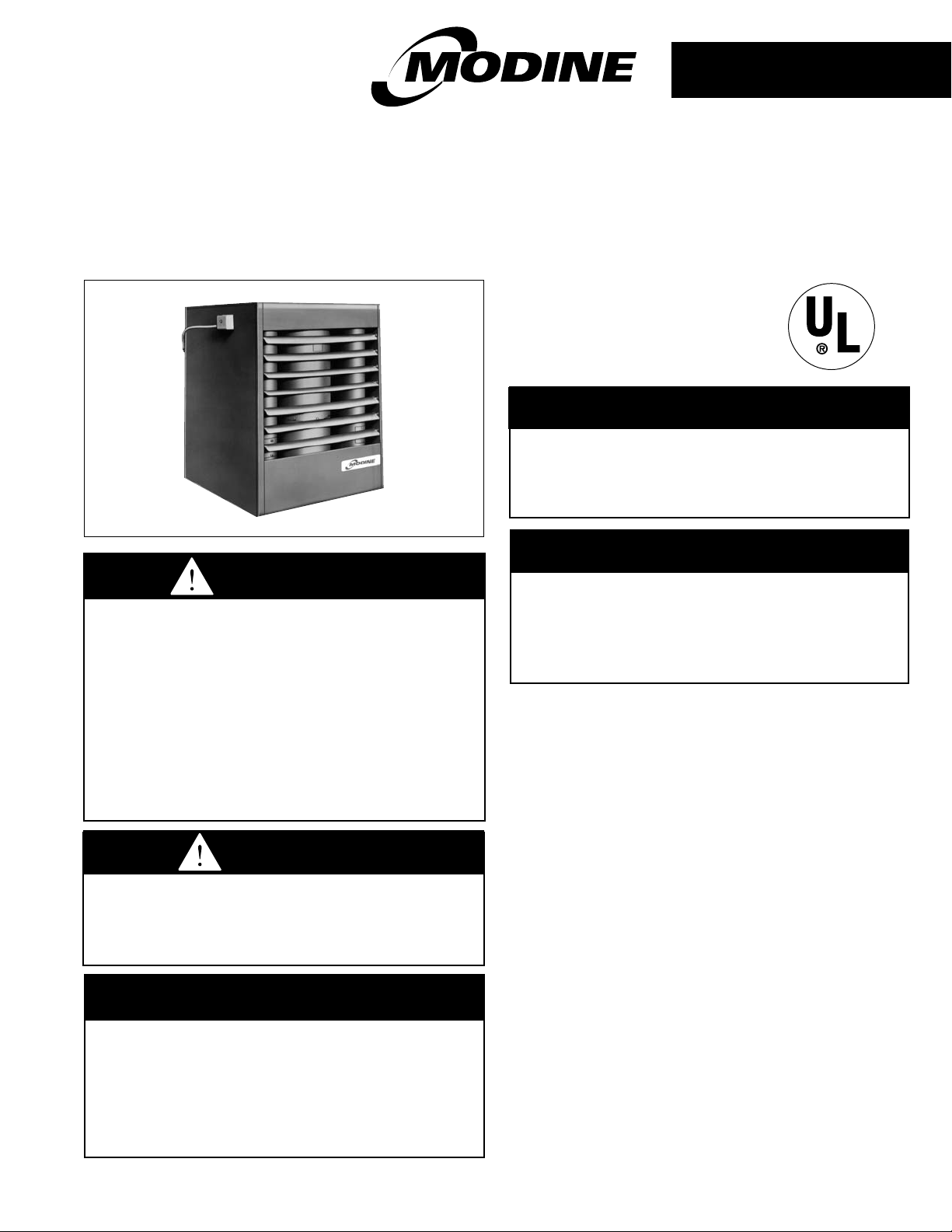
Modine POR 100, POR 145, POR 185 Installation Manual
INSTALLATION AND SERVICE MANUAL
oil-fired unit heaters
model POR
4-522.3
5H75804 Rev.C
Inspection on Arrival
1. Inspect unit upon arrival. In case of damage, report
immediately to transportation company and you local Modine
sales representative.
2. Check rating plate on unit and motor to verify that power
supply and motor specification requirements meet available
electric power at the point of installation.
3. Inspect unit received for conformance with description of
product ordered (including specifications where applicable).
November, 2003
THIS MANUAL IS THE PROPERTY OF THE OWNER.
PLEASE BE SURE TO LEAVE IT WITH THE OWNER WHEN YOU LEAVE THE JOB.
WARNING
Improper installation, adjustment,
alteration, service or maintenance can
cause property damage, injury or death,
and could cause exposure to substances
which have been determined by various
state agencies to cause cancer, birth
defects or other reproductive harm. Read
the installation, operating and maintenance
instructions thoroughly before installing or
servicing this equipment.
CAUTION
To prevent premature heat exchanger
failure do not locate ANY gas-fired units in
areas where chlorinated, halogenated or
acid vapors are present in the atmosphere.
FOR YOUR SAFETY
WHAT TO DO IF YOU SMELL GAS:
1. Open windows.
2. Do not try to light any appliance.
3. Do not touch any electrical switch; do
not use any phone in your building.
4. Immediately call your gas supplier.
FOR YOUR SAFETY
The use and storage of gasoline or other
flammable vapors and liquids in open
containers in the vicinity of this appliance
is hazardous.
IMPORTANT
The use of this manual is specifically
intended for a qualified installation and
service agency. All installation and service
of these units must be performed by a
qualified installation and service agency.
2
SPECIAL PRECAUTIONS / TABLE OF CONTENTS
SPECIAL PRECAUTIONS
THE INSTALLATION AND MAINTENANCE INSTRUCTIONS IN
THIS MANUAL MUST BE FOLLOWED TO PROVIDE SAFE,
EFFICIENT AND TROUBLE-FREE OPERATION. IN
ADDITION, PARTICULAR CARE MUST BE EXERCISED
REGARDING THE SPECIAL PRECAUTIONS LISTED BELOW.
FAILURE TO PROPERLY ADDRESS THESE CRITICAL
AREAS COULD RESULT IN PROPERTY DAMAGE OR LOSS,
PERSONAL INJURY, OR DEATH. THESE INSTRUCTIONS
ARE SUBJECT TO ANY MORE RESTRICTIVE LOCAL OR
NATIONAL CODES.
HAZARD INTENSITY LEVELS
1. DANGER: Indicates an imminently hazardous situation
which, if not avoided, WILL result in death or serious injury.
2. WARNING: Indicates a potentially hazardous situation
which, if not avoided, COULD result in death or serious injury.
3. CAUTION: Indicates a potentially hazardous situation
which, if not avoided, MAY result in minor or moderate
injury.
4. IMPORTANT: Indicates a situation which, if not avoided,
MAY result in a potential safety concern.
DANGER
Appliances must not be installed where they may be exposed
to a potentially explosive or flammable atmosphere.
WARNING
1. Disconnect power supply before making wiring connections to
prevent electrical shock and equipment damage.
2. All appliances must be wired strictly in accordance with wiring
diagram furnished with the appliance. Any wiring different
from the wiring diagram could result in a hazard to persons
and property.
3. Any original factory wiring that requires replacement must
be replaced with wiring material having a temperature
rating of at least 105°C.
4. When servicing or repairing this equipment, use only
factory-approved service replacement parts. A complete
replacement parts list may be obtained by contacting
Modine Manufacturing Company. Refer to the rating plate
on the appliance for complete appliance model number,
serial number, and company address. Any substitution of
parts or controls not approved by the factory will be at the
owner’s risk.
CAUTION
1. Do not locate units in tightly sealed rooms or small
compartments (commonly referred to as confined spaces)
without provisions for adequate combustion air and
venting. Combustion air must have access to the confined
space through a minimum of two permanent openings in
the enclosure, at least one near the bottom. They should
provide a free area of not less than one square inch per
1,000 BTU/Hr input rating of all units in the enclosure with
a minimum of 100 square inches for each opening,
whichever is greater.
2. When oil-fired unit heaters are to be installed in areas
having negative pressure (for example - a space with
exhaust fan(s)) a power venter is recommended.
3. Do not install units below 7 feet, measured from the
bottom of the unit to the floor, unless properly guarded to
provide protection from moving parts.
IMPORTANT
1. To prevent premature heat exchanger failure, do not locate
ANY gas-fired appliances in areas where corrosive vapors (i.e.
chlorinated, halogenated or acid) are present in the
atmosphere.
2. To check most of the Possible Remedies in the troubleshooting
guide listed in Table 18.1, refer to the applicable sections of the
manual.
Table of Contents
Inspection on Arrival . . . . . . . . . . . . . . . . . . . . . . . . 1
Special Precautions . . . . . . . . . . . . . . . . . . . . . . . . . 2
SI (Metric) Conversion Factors . . . . . . . . . . . . . . . . 3
Unit Location . . . . . . . . . . . . . . . . . . . . . . . . . . . . . . 3
Installation . . . . . . . . . . . . . . . . . . . . . . . . . . . . . . . . 4
Operation . . . . . . . . . . . . . . . . . . . . . . . . . . . . . . . . . 11
Service Instructions . . . . . . . . . . . . . . . . . . . . . . . . . 14
Dimensional/Performance Data . . . . . . . . . . . . . . . . 17
Service & Troubleshooting . . . . . . . . . . . . . . . . . . . . 18
Warranty . . . . . . . . . . . . . . . . . . . . . . . . . . . . . . . . . Back Page
CAUTION
4. Do not install unit heater or vent pipe closer than 18
inches to combustible materials in any direction, except
the front of the unit heater, which must be unobstructed.
5. A barometric draft control must be installed on each unit
heater, in the same space as the unit heater and as close
to the unit as possible. See Figure 5.1.
6. Remove bypass plug from fuel unit when unit is connected
to one pipe oil system. Failure to do so will permanently
damage fuel unit and void warranty.
7. Do not mount the OSV more than three feet above the
burner inlet or above the lowest point in fuel line pipings
between burner and OSV. In-line mounting is recommended.
8. Start-up and adjustment procedures should be performed
by a qualified oil serviceman.
9. Do not reset primary control if heat exchanger is hot. If
unit fails to operate properly after resetting twice, consult
qualified oil serviceman.
10. Never use a nozzle size or type other than specified in
Service Instructions.
11. Do not attempt to start the burner when excess oil has
accumulated in the combustion chamber, when the heat
exchanger is full of oil vapor or very hot.
12. Burner adjustments should only be performed by qualified
oil serviceman.
13. Do not reset primary control if heat exchanger is warm.
Wait till cool.
14. To prevent unusual thermal stress and eventual harm to
the heat exchanger, do not operate unit heater without fire pot
or with a damaged fire pot that does not enclose the flame.
15. Do not attempt to reuse any mechanical or electrical
controllers which have been wet. Replace defective controller.
3
GENERAL INFORMATION
Install and wiring of these oil-fired unit heaters must conform to all
applicable local codes, the National Electric Code, and NFPA No.
31 “Installation of Oil Burning Equipment” by the National Fire
Protection Association. Installation of these unit heaters should
only be performed by a qualified oil serviceman.
1. These unit heaters are listed by Underwriters Laboratories,
Inc., with components as furnished.
2. Fuel oil grade No. 1 or 2, with a flash point not less than
100°F, is approved for these unit heaters as specified by
(ASTM) D396-73 Standard Specification for Fuel Oils, or the
Canadian Government Specification Board, 3-GP-28,
(American Society for Testing and Materials).
SI (METRIC) CONVERSION FACTORS / UNIT LOCATION
CAUTION
1. Do not locate units in tightly sealed rooms or small
compartments (commonly referred to as confined spaces)
without provisions for adequate combustion air and
venting. Combustion air must have access to the confined
space through a minimum of two permanent openings in
the enclosure, at least one near the bottom. They should
provide a free area of not less than one square inch per
1,000 BTU/Hr input rating of all units in the enclosure with
a minimum of 100 square inches for each opening,
whichever is greater.
2. When oil-fired unit heaters are to be installed in areas
having negative pressure (for example - a space with
exhaust fan(s)) a power venter is recommended.
IMPORTANT
To prevent premature heat exchanger failure, do not locate ANY
gas-fired appliances in areas where corrosive vapors (i.e.
chlorinated, halogenated or acid) are present in the atmosphere.
DANGER
Appliances must not be installed where they may be exposed
to potentially explosive or flammable atmosphere.
To Convert Multiply By To Obtain
"W.C.
(inches water column)
0.24 kPa
psig 6.893 kpa
°F (°F-32) × 0.555 °C
inches 25.4 mm
feet 0.305 meters
CFM 0.028 m3/min
CFH 1.699 m3/min
btu/ft
3
0.0374 mJ/m
3
pound 0.453 kg
btu/hr 0.000293 kW/hr
gallons 3.785 liters
SI (METRIC) CONVERSION FACTORS
Table 3.1
UNIT LOCATION
Location Recommendations
1. When location the furnace, consider general space and
heating requirements, availability of gas and electrical
supply, and proximity to vent locations.
2. Unit heaters should be located so they discharge air nearly
parallel to exposed walls. Arrange units so they do not blow
directly at occupants. Interference of air streams by
columns, beams, partitions, or other obstructions should be
avoided as much as possible.
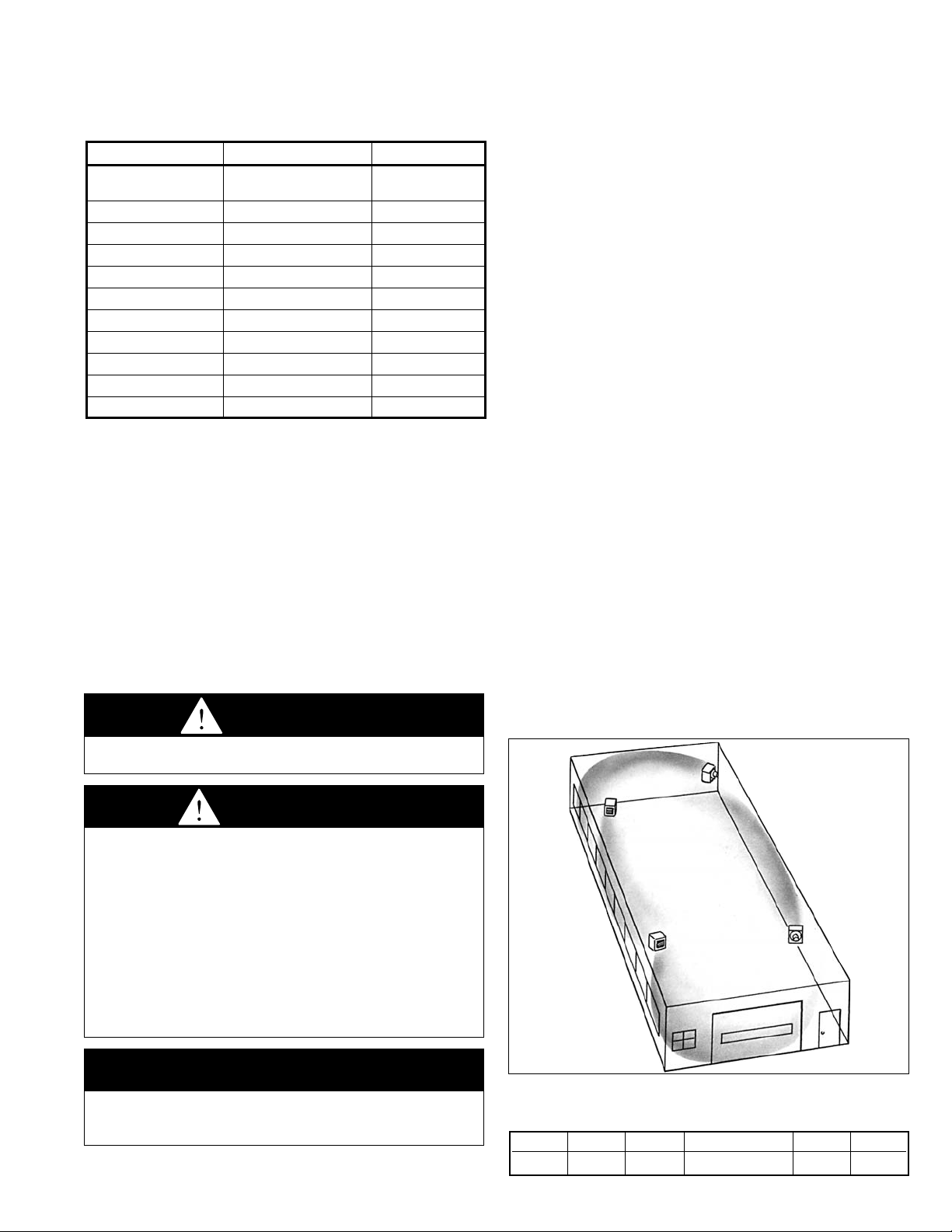
3. In multiple unit installations, arrange units so that each
supports the air stream of the next unit, thus creating
circulatory air movement in the area. See Figure 3.1. A
large portion of the heated air should be directed toward
the side of the building exposed to prevailing winds.
4. When locating units, it is important to consider that the
exhaust vent piping must be connected to the outside
atmosphere.
5. Be sure the structural support at the unit location site is
adequate to support the weight of the unit. For proper
operation the unit must be installed in a level horizontal
position.
6. Do not install units in locations where the flue products can
be drawn into the adjacent building openings such as
windows, fresh air intakes, etc.
7. Be sure that the minimum clearances to combustible
materials and recommended service clearances are
maintained. Units are designed for installation on with the
minimum clearances shown in Table 3.2.
8. Do not install units in locations where gas ignition system is
exposed to water spray, rain, or dripping water.
9. Mounting Height (measured from bottom of unit) at which
unit heaters are installed is critical. Refer to mounting
height information and heat throw data on page 17 of this
manual. The maximum mounting height for any unit is that
height above which the unit will not deliver heated air to the
floor.
Figure 3.1
Typical Unit Locations
Table 3.2
Combustible material and Service Clearances
All Model Sizes
Top Sides Back Front Bottom Flue
18” 18” 18” Unobstructed 18” 18”
4
INSTALLATION
Combustion Air Requirements
For complete combustion, 14-1/2 lbs. of air is required for each
pound of No. 2 fuel oil. Lack of combustion air can cause erratic
burner operation, noisy combustion, fuel odors and soot
deposits on heat exchanger walls resulting in lowered efficiency
and high fuel consumption.
Units installed in tightly sealed buildings or confined spaces
must be provided with two permanent openings, one near the
top of the confined space and one near the bottom. Each
opening should have a free area of not less than one square
inch per 1,000 BTU per hour of the total input rating of all units
in the enclosure with a minimum of 100 square inches for each
opening, whichever is greater, freely communicating with
interior areas having, in turn adequate infiltration from the
outside.
For further details on supplying combustion air to a confined
(tightly sealed) space or unconfined space, see the National
Fuel Gas Code ANSI Z223.1 of CAN/CGA B149.1 or .2
Installation Code, latest edition.
Confined of Unconfined Spaces
The National Fuel Gas Code defines an “unconfined space” as
a space whose volume is greater than 50 cubic feet per 1000
Btu/Hr input of the installed appliance(s). A confined space is 50
cubic feet or less per 1000 Btu/Hr input of the installed
appliance(s).
Unit Suspension
1. Be sure the means of suspension is adequate to support
the weight of the unit (see Table 17.1 for unit weights).
2. For proper operation, the unit must be installed in a level
horizontal position.
3. Clearances to combustibles as previously specified must
be strictly maintained.
4. It is recommended that adequate service access in access
of 18 inches be provided for the burner and fan limit switch.
5. Do not install unit heater above the maximum mounting
height shown in Table 17.2.
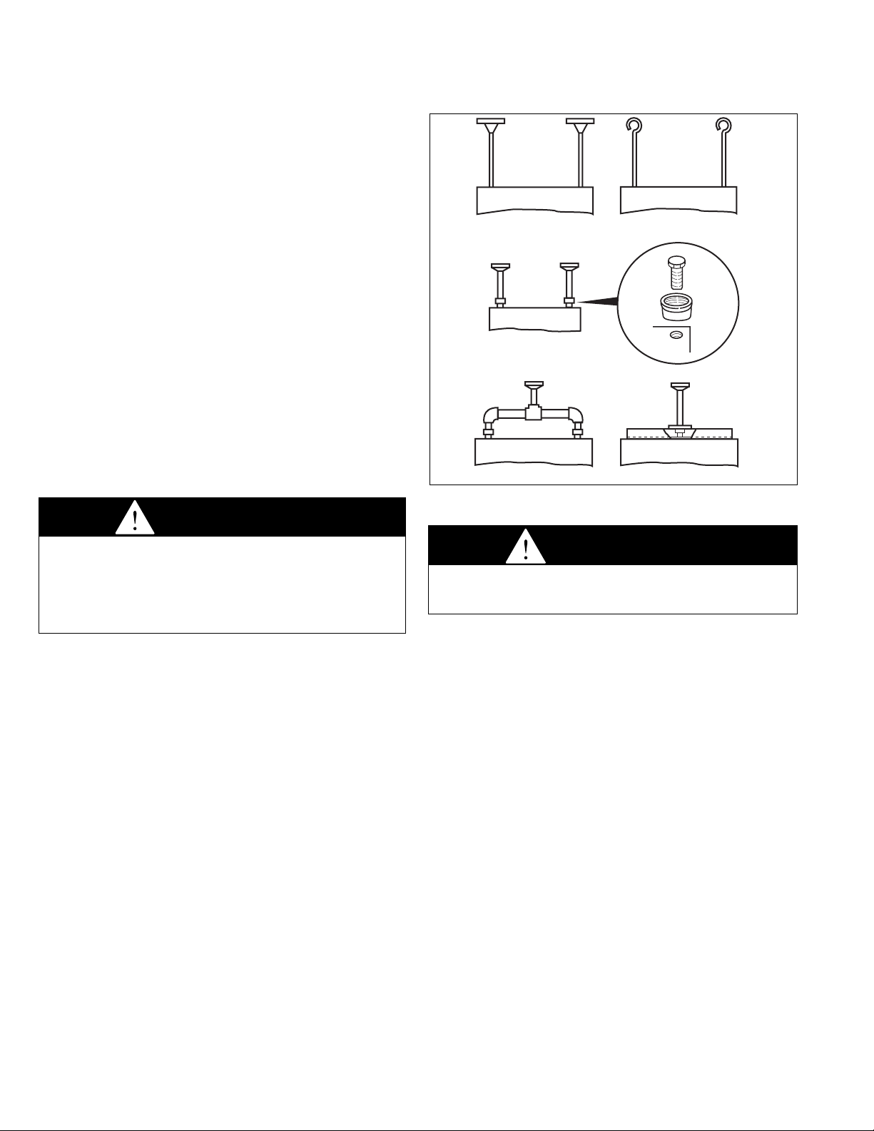
Four tapped holes (1/2" - 13) in the top of the unit are provided
for unit heater suspension. Suspension can be made with
threaded rods, pipes, or ceiling hanger brackets furnished by
others. See Figure 17.1 for hanger hole locations and Figure
4.1 for suspension methods.
NOTE: A pipe hanger adapter kit, shown in figure 4.1 is
available as an accessory from Modine, or can be selffabricated. Kit consists of two drilled 3/4" I.P.S. pipe caps and
two 1/2" - 13 x 1-3/4" capscrews to facilitate threaded-pipe
suspension. Two kits are required for mounting each unit.
Figure 4.1
Suspension Methods
Venting
1. To dispose of flue gasses, all oil-fired heaters must be
vented per NFPA No. 31 “Installation of Oil Burning
Equipment” and all local codes.
2. Do not install chimney connector closer than 18 inches to
combustible materials in any direction. Where chimney
connector passes through a wall or partition, a metal
ventilated thimble not less than 12 inches larger in diameter
than the connector must be used.
3. All Modine oil-fired heaters have an 8 inch vent connection.
Never use a chimney connector smaller than 8 inches,
except a 7 inch adapter may be used on Model POR100 to
accomodate a 7 inch vent.
4. Install a barometric draft control the same size and on the
vent pipe as close to the unit as possible. Installing a
barometric draft control is essential for proper operation of
the unit. Excessive over fire draft can cause unburned fuel
to accumulate in the stack creating a potentially explosive
condition. To install barometric draft control, refer to
instructions furnished by draft control manufacturer. The air
flow opening of the barometric draft control should face the
front of the unit heater or away from air currents in the
vicinity of the heater.
THE BAROMETRIC DRAFT CONTROL MUST BE ADHUSTED
TO PROVIDE MINUS 0.02 INCHES W.C. (WATER COLUMN)
OVERFIRE DRAFT AS MEASURED BETWEEN THE DRAFT
CONTROL AND THE UNIT AND AS CLOSE TO THE UNIT AS
POSSIBLE.
CAUTION
A barometric draft control must be installed on each unit
heater, in the same space as the unit heater and as close to
the unit as possible. See Figure 5.1.
CAUTION
1. Do not install units below 7 feet, measured from the
bottom of the unit to the floor, unless properly guarded to
provide protection from moving parts.
2. Do not install unit heater or vent pipe closer than 18
inches to combustible materials in any direction, except
the front of the unit heater, which must be unobstructed.
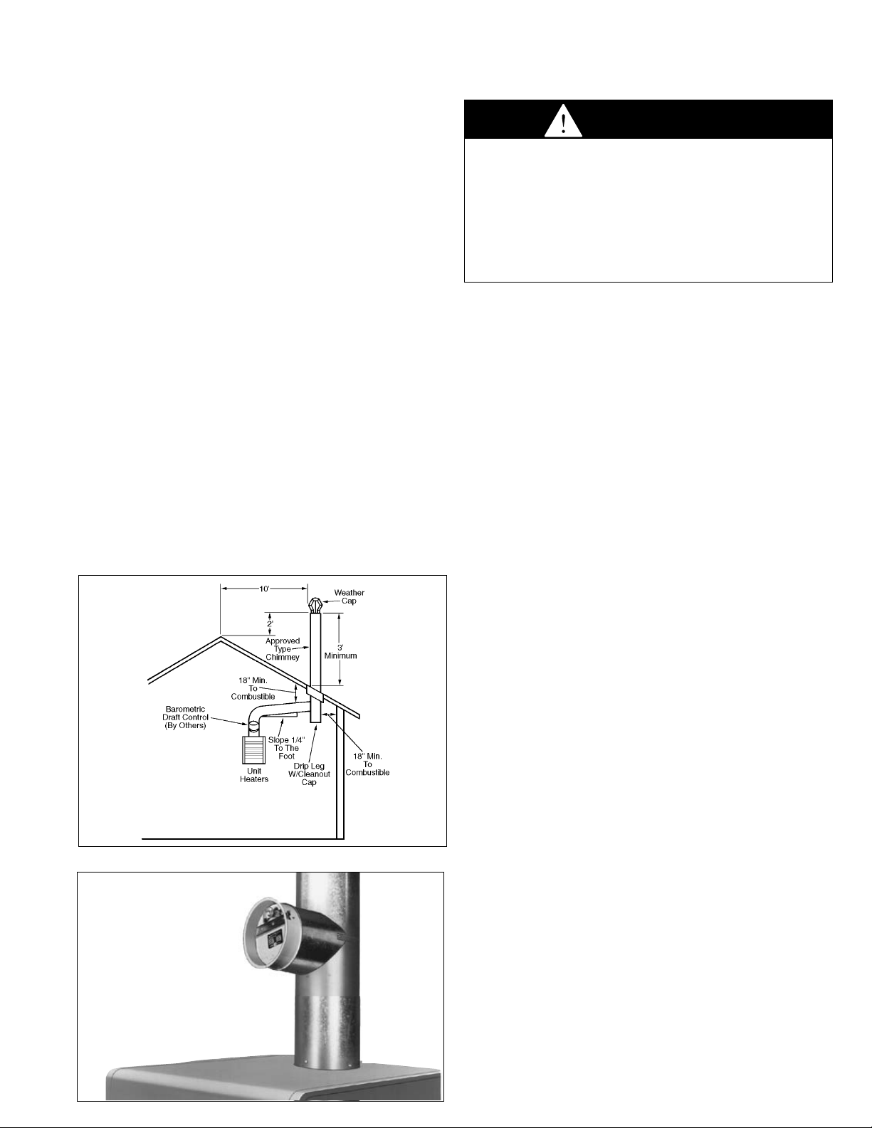
Venting - continued
5. If it is necessary to have an excessively high stack or if the
stack is located such that it is susceptible to updraft
conditions caused by wind, then oversized barometric
dampers should be installed. In extremely windy locations, a
Breidert type vent cap is recommended.
6. For the best venting, the chimney should be as close to the
unit as possible. Keep flue pipes as straight as possible,
avoiding sharp bends. Limit horizontal runs to 75% of
vertical height or a maximum of 10 feet. Horizontal runs in
excess of 10 feet require a draft booster. Chimney
connector must be pitched at a minimum upward slope of
1/4 inch per foot.
7. Condensed flue products will cause rapid corrosion of vent
pipes and heat exchanger. Where possible, avoid venting
through unheated or unoccupied spaces. When necessary,
insulate pipe from cold to maintain draft head and prevent
condensation. Provide a drip leg with a clean-out cap at
bottom of vertical pipe. See Figure 5.1.
8. The chimney must be high enough to provide a minus 0.02
inches W.C. (water column) overfire draft. The top of the
chimney must be at least 3 feet above the highest point
where it passes through the roof and at least 2 feet higher
than any portion of a building within 10 feet of the chimney.
See Figure 5.1.
9. When connecting vent to existing chimney, do not push vent
pipe beyond internal surface of chimney.
10. If making more than one connection into the same chimney,
the chimney connectors must enter at different levels and
the area of the chimney must be equal to or greater than the
combined areas of the individual connectors.
Figure 5.1 - Typical Venting Arrangement
Figure 5.2 - Barometric Draft Control Above Unit
Wiring
General
All wiring must be done in accordance with the National Electric
Code, latest edition, (NFPA No. 70). Canadian electrical code
C22.1 applies in Canada.
Unit Heater Wiring
All internal wiring to the burner motor, fan motor and the fan and
limit control has been completed at the factory. Provide 115-volt
electric service from a fused disconnect switch to the octagon
junction box on the rear of the unit heater. Wire must be
insulated to 60°C and must be a minimum of 14-gauge (AWG)
copper in at least 1/2 inch thin-wall or flexible metal conduit.
Thermostat Wiring
The proper wiring for a single thermostat for each unit heater is
shown in Figure 6.1. The multiple unit wiring diagram shown in
Figure 6.2 illustrates typical wiring and connections used with a
centralized oil distribution system for multiple unit installations.
This diagram is provided as a reference only, and is not
intended to satisfy any particular local code requirements.
System operation and compliance with local codes is the
responsibility of the installer.
As shown, this system includes a relay for low voltage control of
the booster pump, and the line voltage power supply to the
booster pump motor. Figure 6.2 also shows the proper
connections for multiple unit heaters, each controlled by a
thermostat. In this arrangement, a 25V power source is
connected to pressure switches on each unit. Upon demand for
heat, a thermostat energizes the controls which start each
burner. Meanwhile, separate pressure switches, on the fuel unit,
sense an increase in oil pressure, and close their contacts to
activate the booster pump switching relay, which in turn starts
the booster pump. Optional high and low pressure controllers
can supply line pressure. Location of a remote, low-voltage
thermostat should be determined by the heating requirements
and be mounted on an inside wall approximately 5 feet above
the floor. It must not be located where it would be affected by
direct heat from the unit or other sources or drafts from
frequently opened doors or windows. See instructions packed
with thermostat. The unit may also be controlled by a remote
U.L. listed manual on-off switch.
5
INSTALLATION
WARNING
1. Disconnect power supply before making wiring connections to
prevent electrical shock and equipment damage.
2. All appliances must be wired strictly in accordance with wiring
diagram furnished with the appliance. Any wiring different
from the wiring diagram could result in a hazard to persons
and property.
3. Any original factory wiring that requires replacement must
be replaced with wiring material having a temperature
rating of at least 105°C.

6
A
N
A
X
D
A
INSTALLATION
Figure 6.1
Single Unit Wiring Diagram
Figure 6.2
Typical Multiple Unit Installation and Booster Pump Wiring Diagram
WARNING
All appliances must be wired strictly in accordance
with wiring diagram furnished with the appliance.
Any wiring different from the wiring diagram could
result in a hazard to persons and property.
FIELD WIRING
CONNECTIONS
(WIRE NUTS
BY OTHERS)
W
BK
FAN
MOTOR
Wiring Legend
FACTORY
FIELD
WIRE NUT
FAN & LIMIT
CONTROL
FAN LIMIT
BL
BK
115V/60HZ/1∅
FUSED DISCONNECT
SWITCH (BY OTHERS)
FAN
SWITCH
LIMIT
R
CONTROL
FAN
MOTOR
BURNER
MOTOR
GROUN
IN J-BO
BURNER
MOTOR
W
BK
W
W
CAD
IGNITOR
CELL
BURNER HOUSING
LL WIRING MUST CONFORM TO
ATIONAL ELECTRIC CODE NFPA #70
ND APPLICABLE LOCAL CODES
JUNCTION BOX
ON BURNER
GR
BK
W
OR
BL
T
PRIMARY
T
CONTROL
F
F
Single-phase, intermittent ignition,
low voltage thermostat
GROUND
EQUIPMENT
GROUND
LOW
VOLT.
THERM.
(BY OTHERS)
FUSED DISCONNECT
SWITCH (BY OTHERS)
115V/60 HZ/1∅
FIELD WIRING
JUNCTION BOX
(ON HEATER)
USE COPPER
CONDUCTORS ONLY
W
BK
BK
OR
PRIMARY
CONTROL
IGNITOR
WBL
T
LOW VOLT.
THERMOSTAT
T
F
CAD CELL
F
5H70833B REV.
 Loading...