

Page 1
!
!
!
!
2-528
August 2023
INSTALLATION AND SERVICE MANUAL
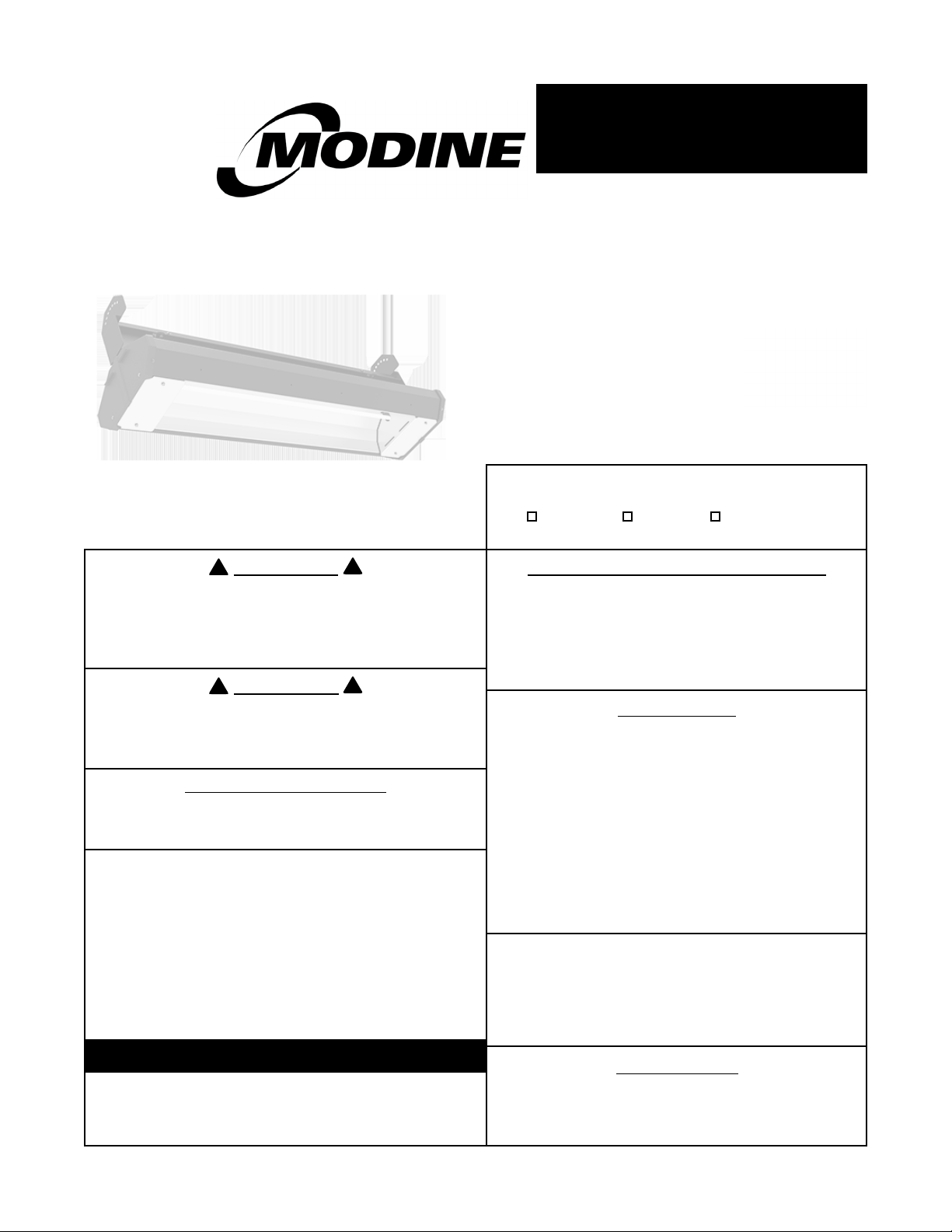
Overhead Electric Infrared Heaters
Models MEL
INSTRUCTIONS APPLY TO:
Installation Operation Maintenance
WARNING
Improper installation, adjustment, alteration, service or
maintenance can cause property damage, injury or
death. Read the installation, operating, and service/
maintenance instructions thoroughly before installing or
servicing this equipment.
WARNING
Outdoor residential use only. Installation of this infrared
heater system in residential indoor spaces, RVs, mobile
homes, etc. may result in property damage, re, serious
injury, or death.
FOR YOUR SAFETY
The use and storage of gasoline or other ammable
vapors and liquids in the vicinity of this appliance is
hazardous.
Inspection on Arrival
1. Inspect unit upon arrival. In case of damage, report it
immediately to transportation company and your local
Modine sales representative.
2. Check rating plate on unit to verify that power supply
and motor specication requirements meet available
electric power at the point of installation.
3. Inspect unit upon arrival for conformance with
description of product ordered (including specications
where applicable).
IMPORTANT
The use of this manual is specically intended for a
qualied installation and service agency. A qualied
installation and service agency must perform all
installation and service of these appliances.
HAZARD INTENSITY LEVELS
• DANGER: Failure to comply will result in severe
personal injury or death and property damage
• WARNING: Failure to comply could result in severe
personal injury or death and/or property damage.
• CAUTION: Failure to comply could result in minor
personal injury and/or property damage.
CONTENTS
Section Page
1. Safety ....................................................................3
2. Installation ........................................................... 11
3. Maintenance ....................................................... 18
4. Parts List .............................................................20
5. Limited Warranty ................................................. 23
These heaters must NOT be used in the
following applications:
• Enclosed swimming pool areas
• Areas with contaminated atmospheres.
• Areas requiring explosion-proof equipment.
• Process heating applications.
ATTENTION
Mount a copy of these instructions adjacent to
the heater and retain a copy for future reference.
Page 2
MEL Series
!
Contents
1.0 Safety .......................................................................... 3
Safety Symbols............................................................. 3
Applications ............................................................... 3
Model Number Designation Chart . . . . . . . . . . . . . . . . . . . . . . . . . . . . . . . . . . . . . . . . . . . . . 4
Available Models and Specifications ........................................... 4
Clearances to Combustibles .................................................. 7
Safety Labels and Their Locations . . . . . . . . . . . . . . . . . . . . . . . . . . . . . . . . . . . . . . . . . . . . . 9
Standards, Certifications, and Government Regulations .......................... 10
2.0 Installation . . . . . . . . . . . . . . . . . . . . . . . . . . . . . . . . . . . . . . . . . . . . . . . . . . . . . . . . . . . . . . . . . . . . . 11
Design .................................................................. 11
Heater Mounting .......................................................... 13
Lamp Installation .......................................................... 15
Outdoor Application........................................................ 16
Electrical Wiring ........................................................... 16
3.0 Maintenance . . . . . . . . . . . . . . . . . . . . . . . . . . . . . . . . . . . . . . . . . . . . . . . . . . . . . . . . . . . . . . . . . . . 18
Troubleshooting Guide . . . . . . . . . . . . . . . . . . . . . . . . . . . . . . . . . . . . . . . . . . . . . . . . . . . . . 19
Heater Assembly Components ................................................20
Parts List ................................................................. 21
4.0 Limited Warranty................................................................ 23
WARNING
California Proposition 65
This product can expose you to chemicals including lead, which is known to the State of California to cause
birth defects or other reproductive harm.
For more information, go to www.P65Warnings.ca.gov.
2
Page 3
MEL Series
!
!
!
!
!
!
1.0 Safety • Safety Symbols • Applications
1.0 Safety
WARNING
Improper installation, adjustment, alteration, service, or maintenance can cause property
damage, serious injury, or death. Read and understand the installation, operating, and
maintenance instructions thoroughly before installing or servicing this equipment. Only
trained, qualified personnel with proper electrical experience may install or service this
equipment.
Safety Symbols
Safety is the most important consideration during installation, operation, and maintenance of the infrared
heater. You will see the following symbols and signal words when there is a hazard related to safety or
property damage.
Warning indicates a potentially hazardous
WARNING
situation which, if not avoided, could result in
death or injury.
Caution indicates a potentially hazardous
CAUTION
NOTICE
situation which, if not avoided, could result in
minor or moderate injury.
Notice indicates a potentially hazardous situation
which, if not avoided, could result in property
damage.
Applications
This is not an explosion proof heater. No MEL series heater may be used in a Class 1 or Class 2 Explosive
Environment. Consult your local fire marshal, insurance carrier, and other authorities for approval if the
proposed installation is in question.
Commercial / Industrial (Indoors & Outdoors)
Infrared heaters are designed and certified for use in industrial and commercial buildings such as
warehouses, manufacturing plants, aircraft hangars, and vehicle maintenance shops. For maximum safety,
the building must be evaluated for potential hazards before installing the heater system. A critical safety
factor to consider before installation is the clearances to combustibles.
Outdoor Residential Only
This heater is NOT approved for use in an indoor residential application. This includes, but is not limited to,
attached garages, living quarters, solariums, etc. Consult the local fire marshal and/or insurance provider if
unsure of your application.
WARNING
Not For Residential Use.
Installation of this infrared heater system in residential indoor spaces, RVs,
mobile homes, etc. may result in property damage, fire, serious injury, or death.
3
Page 4
1.0 Safety • Model Number Designation Chart • Available Models
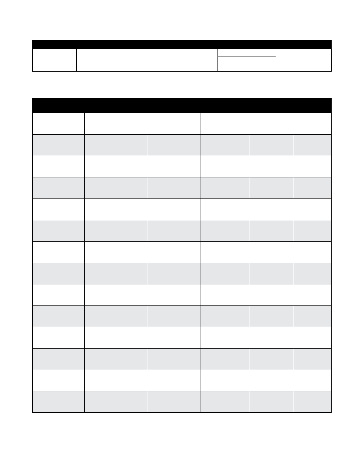
Chart 1.1 • Model Number Designation Chart
Series Material Type Lamp Quantity Voltage
MEL-24
MEL-33
MEL-46
Model Configuration Examples: MEL-24B1-120
B = Black Powder Coat with Black Nylon End Caps
1
2
3
Chart 1.2 • Available Models and Specifications - 24”
Series Lam p Typ e Voltage* Tota l A mp s Tota l Wa t ts BTU/h
MEL Series
120
208
240
277
480
575
MEL-24B1-120
MEL-24B1-208
H.O. Medium Wave 120 V 11.30 1,360 4,6 41
H.O. Medium Wave 208 V 6.53 1,360 4,6 41
MEL-24B1-240 H.O. Medium Wave 240 V 5.66 1,360 4,6 41
MEL-24B1-277 H.O. Medium Wave 277 V 4.90 1,360 4,6 41
MEL-24B1-480 H.O. Medium Wave 480 V 2.83 1,360 4,6 41
MEL-24B2-120 H.O. Medium Wave 120 V 22.60 2,720 9,281
MEL-24B2-208 H.O. Medium Wave 208 V 13.06 2,720 9,281
MEL-24B2-240 H.O. Medium Wave 240 V 11.32 2,720 9,281
MEL-24B2-277 H.O. Medium Wave 277 V 9.80 2,720 9,281
MEL-24B2-480 H.O. Medium Wave 480 V 5.66 2,720 9,281
MEL-24B3-208 H.O. Medium Wave 208 V 19.59 4,080 13,922
MEL-24B3-240 H.O. Medium Wave 240 V 16.9 8 4,080 13,922
MEL-24B3-277 H.O. Medium Wave 277 V 14.70 4,080 13,922
MEL-24B3-480 H.O. Medium Wave 480 V 8.49 4,080 13,922
4
Page 5
MEL Series
1.0 Safety • Available Models
Chart 1.3 • Available Models and Specifications - 33”
Series Lam p Type Voltage* Tota l A mp s Tota l Wa t ts BTU/h
MEL-33B1-208 H.O. Medium Wave 208 V 10.20 2,125 7, 251
MEL-33B1-24 0 H.O. Medium Wave 240 V 8.85 2,125 7, 2 51
MEL-33B1-277 H.O. Medium Wave 277 V 7.67 2,125 7, 251
MEL-33B1- 480 H.O. Medium Wave 480 V 4.42 2,125 7, 2 51
MEL-33B2-208 H.O. Medium Wave 208 V 20.40 4,250 14,502
MEL-33B2-240 H.O. Medium Wave 240 V 17.70 4,250 14,502
MEL-33B2-277 H.O. Medium Wave 277 V 15.34 4,250 14,502
MEL-33B2-480 H.O. Medium Wave 480 V 8.84 4,250 14,502
MEL-33B3-277 H.O. Medium Wave 277 V 23.01 6,375 21,752
MEL-33B3-480 H.O. Medium Wave 480 V 13.26 6,375 21,752
* Heaters are configured at the factory for single phase wiring. If three phase service is desired, it must be
wired as such in the field by a trained installer / electrical contractor.
5
Page 6

1.0 Safety • Available Models
MEL Series
Chart 1.4 • Available Models and Specifications - 46”
Series La mp Ty pe Voltage* Tot al Am ps Tot al Wat ts BTU/h
MEL- 46B1-277 H.O. Medium Wave 277 V 11.55 3,200 10,919
MEL-46B1-480 H.O. Medium Wave 480 V 6.66 3,200 10,919
MEL- 46B1-575 H.O. Medium Wave 575 V 5.56 3,200 10,919
MEL-46B2-277 H.O. Medium Wave 277 V 23.10 6,400 21,838
MEL-46B2-480 H.O. Medium Wave 480 V 13.32 6,400 21,838
MEL-46B2-575 H.O. Medium Wave 575 V 11.12 6,400 21,838
MEL-46B3-480 H.O. Medium Wave 480 V 19.98 9,600 32,757
MEL-46B3-575 H.O. Medium Wave 575 V 16.68 9,600 32,757
* Heaters are configured at the factory for single phase wiring. If three phase service is desired, it must be
wired as such in the field by a trained installer / electrical contractor.
6
Page 7
MEL Series
!
!
1.0 Safety • Clearances to Combustibles
Clearances to Combustibles
WARNING
Placement of explosive objects, flammable objects, liquids, and
vapors close to the heater may result in explosion, fire, property
damage, serious injury, or death. Do not store or use explosive
objects, liquids, or vapors in the vicinity of the heater.
Failure to comply with the published clearances to combustibles could result in personal injury, death, and/
or property damage.
The outside surfaces of the heater are hot during operation and after operation. If contact is made,
permanent skin damage may occur. Do not move, handle, or service the unit during operation or while hot.
CAUTION
Signs shall be posted specifying the maximum permissible stacking height in order to
maintain clearances to combustibles.
Hazards Include:
For maximum safety the building must be evaluated for hazards before installing the heater system. Examples
include, but are not limited to:
• Gas and electrical lines
• Combustible and explosive materials
• Chemical storage areas
• Areas of high chemical fume concentrations
• Provisions for accessibility to the heater
• Adequate clearances around air openings
• Vehicle parking areas
A critical safety factor to consider before installation is the clearances to combustibles. Clearance to
combustibles is defined as
combustible item
following is a partial list of items to maintain clearances from:
. Considerations must also be made for moving objects around the infrared heater. The
the minimum distance you must have between the indicated surface and the
• Vehicles with lifts or cranes
• Storage areas with stacked materials
• Lights
• Sprinkler heads
• Overhead doors and tracks
• Dirty, contaminated environment
Combustible Items Include: Moving Objects Include:
• Wood • Overhead doors
• Paper • Vehicles on lifts
• Fabric • Cranes
• Chemicals • Hoists
• Wall or roof insulation
• Plastics
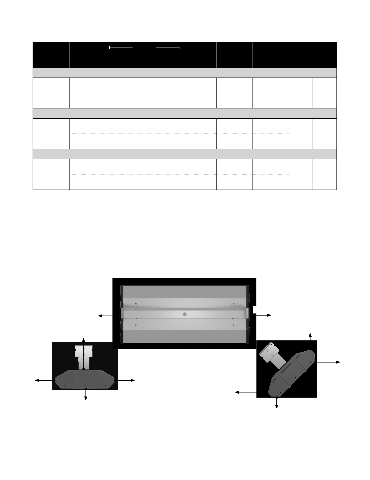
When installing the infrared heater system, the minimum clearances to combustibles must be maintained.
These distances are shown in Chart 1.5 and on the heater. If you are unsure of the potential hazards, consult
your local fire marshal, fire insurance carrier, or other qualified authorities on the installation of infrared
heaters for approval of the proposed installation.
7
Page 8
1.0 Safety • Clearances to Combustibles
Chart 1.5 • Clearances to Combustibles in Inches (Millimeters) - see Figure 1.1
MEL Series
Min. Mtg.
Height
US Canada
Length
Mounting
Angle
Side
Front Behind
End To p Below
Single Element
24’’
33’’
46’’
0° 16 (407) 16 (407) 12 (305) 6 (153) 56 (1423)
6 ft. 2.4 m
45° 47 (1194) 4 (102) 12 (305) 10 (254) 40 (1016)
Double Element
24’’
33’’
46’’
0° 28 (712) 28 (712) 26 (661) 6 (153) 86 (2185)
7.5 ft. 2.4 m
45° 86 (2185) 4 (102) 26 (661) 10 (254) 86 (2185)
Triple Element
24’’
33’’
46’’
0° 31 (788) 31 (788) 34 (864) 9 (229) 105 (2667)
9 ft. 2.8 m
45° 105 (2667) 4 (102) 34 (864) 10 (254) 105 (2667)
* Heaters mounted on an angle between 0° and 45° must maintain clearances posted for 0° or 45°,
whichever is greater.
** Clearances to combustibles must be maintained when using recessed mount kits (P/N: ELx-FRxx). For
additional information, refer to form # LSH123a - Recessed Mounting Frame Installation Instructions or
contact the factory.
NOTE: Ensure that building materials with a low heat tolerance (i.e, awnings, fabrics, plastics, sprinklers,
insulation, etc.) are protected against degradation. This may require the heater to be mounted at a distance
in excess of the published clearances to combustibles. Contact the material manufacturer for specific details.
Figure 1.1 • Clearances to Combustibles
END END
TOP
BELOW
END VIEW
0° Mounting Angle
TOP VIEW
0° Mounting Angle
SIDESIDE
BEHIND
BELOW
END VIEW
45° Mounting Angle
TOP
FRONT
8
Page 9
MEL Series
- INSTALLER: READ AND POST THIS NOTICE -
SAMPLE
1.0 Safety • Safety Labels and Their Locations
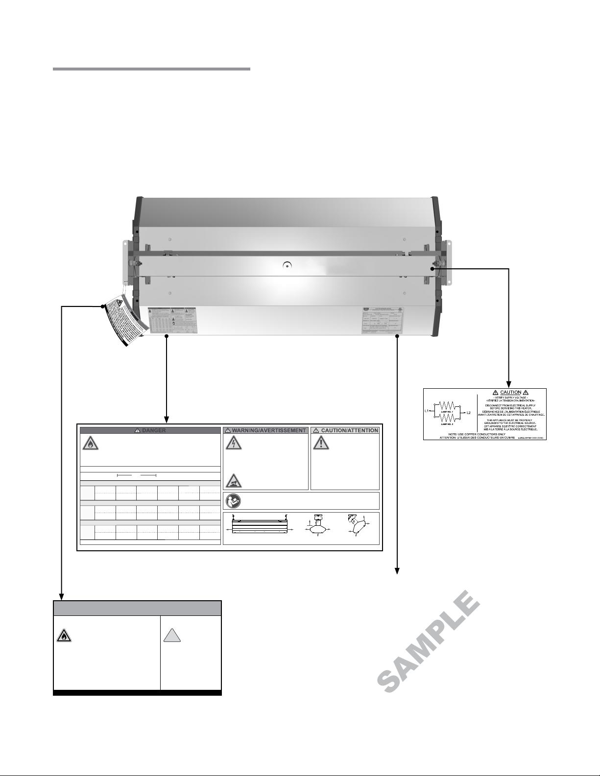
Safety Labels and Their Locations
It is important to provide warnings to alert individuals to potential hazards and safety actions. Signs should
state the hazards for the particular application and be legible to the building occupants. Consult the factory or
a factory representative for additional information on signage compliance.
Safety warning labels must be maintained on the infrared heater. Illustrations of the safety labels and their
locations are pictured below. When no longer legible, they must be replaced. Contact either your local
distributor or the product manufacturer for obtaining replacement signs or labels.
Top View
FIRE HAZARD. Always maintain published clearances to
combustibles. In locations used for the storage of combustible
materials, signs must be posted.
DANGER D’INCENDIE. Toujours maintenir un dégagement
publié à combustibles. Dans les endroits utilisés pour le stockage
de matériaux combustibles, panneaux doivent être installés.
CLEARANCES TO COMBUSTIBLES - Inches (Millimeters)
Mounting Side
Length Angle Front Behind End Top Below
Single Element
24”
0°
16 (407)
16 (407)
12 (305)
33”
45°
47 (1194)
28 (712)
86 (2185)
31 (788)
105 (2667)
4 (102)
28 (712)
4 (102)
31 (788)
4 (102)
46”
Double Element
24”
0°
33”
45°
46”
Triple Element
24”
0°
33”
45°
46”
Heaters mounted on an angle between 0° and 45° must maintain clearances posted for 0° or 45°, whichever is greater.
12 (305)
26 (661)
26 (661)
34 (864)
34 (864)
6 (153)
10 (254)
6 (153)
10 (254)
9 (229)
10 (254)
F/N: LLECL001a - Clearances to Combustibles Label
WARNING
Avoid Serious Injury, Death, or Property Damage.
Maintain Clearances to Combustible to Prevent the Risk of Fire.
Clearances to combustibles must be maintained at
all times in order to prevent the ignition of
combustible materials. In locations used for the
storage of combustible materials, signs must be
posted to specify the maximum permissible stacking height to
maintain the required clearances from the heater to the
combustibles. Signs must either be posted adjacent to the
heater’s thermostats or, in the absence of such thermostats, in a
conspicuous location. Clearances are provided on the heater’s
safety label and in the heater’s Installation, Operation, and
Maintenance manual. Product installation and operation must
comply with applicable standards, codes, and regulations. Post
this tag adjacent to the heater’s thermostat or controls before
operating the heater.
California Proposition 65
This product can
expose you to
chemicals including
!
lead and carbon
monoxide, which are known to the
State of California to cause birth
defects or other reproductive harm.
For more information go to
www.P65Warnings.ca.gov.
F/N: LL001 - Clearance Safety Tag
(Ax adjacent to heater’s controller)
SHOCK HAZARD. Disconnect all
supplies before working on any
circuit.
RISQUE D’ÉLECTROCUTION. Débrancher
toutes les alimentations avant d'exécuter des
travaux sur un circuit quelconque.
Heater MUST be properly
grounded prior to operation.
HOT. Do not touch any part of
56 (1423)
40 (1016)
86 (2185)
86 (2185)
105 (2667)
105 (2667)
LL001-XM-07/18 (CDS)
the heater while in operation.
Read and understand the installation, operating, and maintenance
instructions thoroughly before installing or servicing this equipment. Failure
to properly apply product may result in property damage, injury, or death.
ÉVITEZ LES PANNES
D'ÉQUIPEMENT. Employer des fils
d'alimentation adéquats pour
200°C.
Apply proper voltage.
Top
EndEnd
Side
Below
END VIEW - 0°SIDE VIEW - 0°
AVOID EQUIPMENT
FAILURE. Use supply
wires suitable for 200°C
or equivalent.
Behind
Side
Below
END VIEW - 45°
LLECL001a-1x-07/20 (XXX)
Electrical Label
(Located inside the raceway)
Top
Front
Rating Plate
9
Page 10

1.0 Safety • Standards, Certifications, and Government Regulations
MEL Series
Standards, Certifications, and Government Regulations
Installation of this infrared heater must comply with all applicable local, state, and national specifications,
regulations, and building codes. Contact the local building inspector and/or fire marshal for guidance.
The heater must be electrically grounded in accordance with the following codes:
®
United States: Refer to National Electrical Code
Wiring must conform to the latest edition of National Electrical Code
ordinances, and any special diagrams from the manufacturer.
Canada: Refer to Canadian Electrical Code CSA C22.1 Part 1 (latest edition).
Modine units comply with or are certified by one or more of the following organizations or
standards:
• UL 2021
• CSA 22.2 #46 - M1988
, ANSI/NFPA 70 (latest edition).
®
, local
10
Page 11
MEL Series
!
!
2.0 Installation • Design
2.0 Installation
WARNING
Read and understand the installation, operation, and maintenance instructions thoroughly
before installing or servicing this equipment.
Design
To ensure a safe, properly designed heating system, a layout should be developed for the correct placement
of the infrared heater(s).
Aside from safety factors such as clearances to combustibles (see Chart 1.5 on page 8), consideration should
also be given to factors such as the environment (e.g., cold/drafty, average, protected), heat coverage (sq. ft.)
needed, heater centers, the distance behind a person or work station(s), etc. Also, the eective infrared
surface temperature of a person or object may be diminished with wind above 5 mph. Wind barrier(s) may be
required. Most importantly, clearances to combustibles must always be maintained! Refer to hazards on page
7.
When positioning the heaters, keep in mind the location of combustible materials, lights, sprinkler heads,
overhead doors, storage areas with stacked materials, gas and electrical lines, parked vehicles, cranes, etc.
Refer to page 6 for minimum clearances to verify that a safe installation exists.
This installation manual, along with national, state, provincial, and local codes, addresses these issues. It is
critical that you read, understand, and follow all guidelines and instructions. Always inspect and evaluate the
mounting conditions, application, and wiring.
When heated, materials high in hydrocarbons (solvents, paint thinner, mineral spirits, formaldehydes, etc.)
can evaporate and/or degrade. This may result in odors or fumes being emitted into the environment. To
correct this problem, clean the area and/or introduce additional ventilation. Heaters installed and serviced in
accordance with the installation manual do not emit foul odors into the environment.
IMPORTANT: Fire sprinkler heads must be located at an appropriate distance from the heater to avoid an
inadvertent discharge. This distance may exceed the published clearances to combustibles. Certain
applications may require the use of high temperature sprinkler heads or relocation of the heaters.
CAUTION
Fire sprinkler systems containing propylene glycol, antifreeze, or other potentially flammable substances
shall not be used in conjunction with this heater without careful consideration for, and avoidance of,
inadvertent discharge hazards. For further information consult applicable NFPA codes. Always observe
applicable state and local codes.
11
Page 12
2.0 Installation • Design
MEL Series
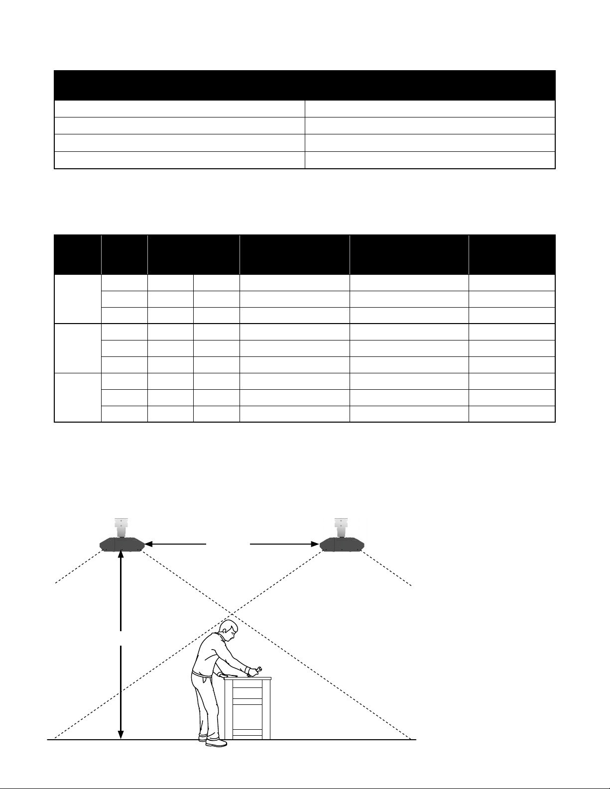
Chart 2.1 • Estimating Required Heat Load
Watts Required per Square
Type of Building
Foot at Floor Level*
Insulated 5 to 10
Uninsulated 10 to 15
Outdoor Sheltered 20 to 30
Outdoor Unsheltered 25 to 40
* For load purposes only, not for determining coverage.
When comfort heating people, two heaters should be used to heat both sides of the individual. Heater
installation shall comply with all IOPM, NEC, ANSI/NFPA-70, CEC, and local restrictions.
Chart 2.2 • Heating Application Chart
Series
Lamp
Quantity
Minimum Mounting
Height (Ft.)
US Canada
Recommended
Mounting Height (Ft.)**
[Dim. A]
Recommended Distance
Between Heaters (Ft.)
[Dim. B]
Approximate†
Square Foot
Coverage
1 6 ft. 2.4 m 10 to 12 5 to 10 100 to 200
MEL-24
2 7.5 ft. 2.4 m 10 to 12 6 to 12 150 to 250
3 9 ft. 2.8 m 12 to 14 7 to 14 200 to 300
1 6 ft. 2.4 m 10 to 12 6 to 12 200 to 300
MEL-33
2 7.5 ft. 2.4 m 12 to 14 7 to 14 250 to 350
3 9 ft. 2.8 m 12 to 14 8 to 16 300 to 400
1 6 ft. 2.4 m 12 to 14 7 to 14 300 to 400
MEL-46
2 7.5 ft. 2.4 m 14 to 16 8 to 16 350 to 450
3 9 ft. 2.8 m 14 to 16 9 to 18 400 to 500
** Clearances to combustibles published in this manual and on safety labels must be maintained at all times.
Factory recommended mounting heights are listed as a guideline. If infrared heaters are mounted too low or
too high, they may result in discomfort or lack of heat.
†
Approximation only. Mounting height and environmental conditions will impact performance.
Figure 2.1 • Heating Application
Dim A
Dim B
NOTE: Typical height above
patrons is 2 to 6 ft. (minimum
required mounting height must
always be maintained).
Heat loads estimated are to
achieve a perceived 10° to 15°F
outdoor temperature rise.
12
Page 13
MEL Series
!
2.0 Installation • Heater Mounting
Heater Mounting
WARNING
Improper suspension of the infrared heater may result in collapse and being crushed. Always
suspend from a permanent part of the building structure that can support the total force and
weight of the heater.
Failure to maintain minimum clearance to combustibles may result in fire and/or explosion,
property damage, serious injury, or death. Always maintain minimum clearances and post
signs or provided tags (F/N: LL001) adjacent to heater’s controller. Signs should state the
hazards for the particular application and be legible to the building occupants. Consult the
factory or a factory representative for additional information on signage compliance.
The heater can be suspended with chains or rigid threaded rod. Local codes, or conditions that would cause
the unit to move (e.g., wind drafts, blowers, crane rails, etc.), may require rigid threaded rod. Consult all
applicable codes before installation.
Clearances to combustibles must be maintained when using recessed mount kits (P/N: ELx-FRxx). For
additional information, refer to form # LSH123a - Recessed Mounting Frame Installation Instructions or
contact the factory.
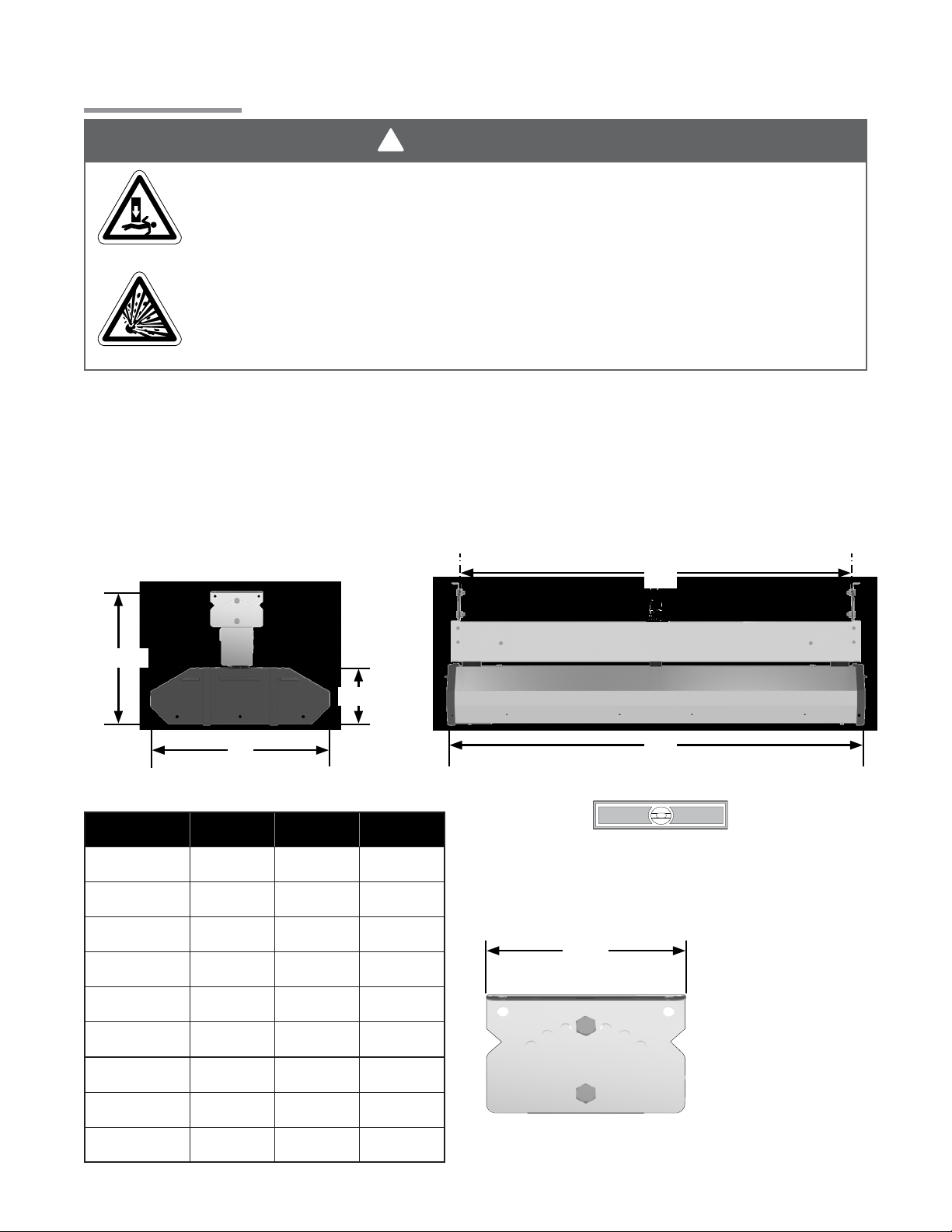
The heater must be level from end to end and may be 0° to 45° on horizontal. Refer to Figures 2.2 and 2.3.
Figure 2.2 • Heater Dimensions
11.625”
4.75”
B
Chart 2.3 • Physical Dimensions (inches)
Model No. A B C
MEL-24B1 23.50 9.625 24.50
MEL-24B2 23.50 15.25 24.50
MEL-24B3 23.50 21.00 24.50
MEL-33B1 32.50 9.625 33.50
(Center of Mounts)
Mount Heater Level
Figure 2.3 • Mounting Centers
3.75”
A
C
- End to End -
MEL-33B2 32.50 15.25 33.50
MEL-33B3 32.50 21.00 33.50
MEL-46B1 45.50 9.625 46.50
MEL-46B2 45.50 15.25 46.50
MEL-46B3 45.50 21.00 46.50
13
Page 14
2.0 Installation • Top Channel Assembly
MEL Series
Top Channel Assembly
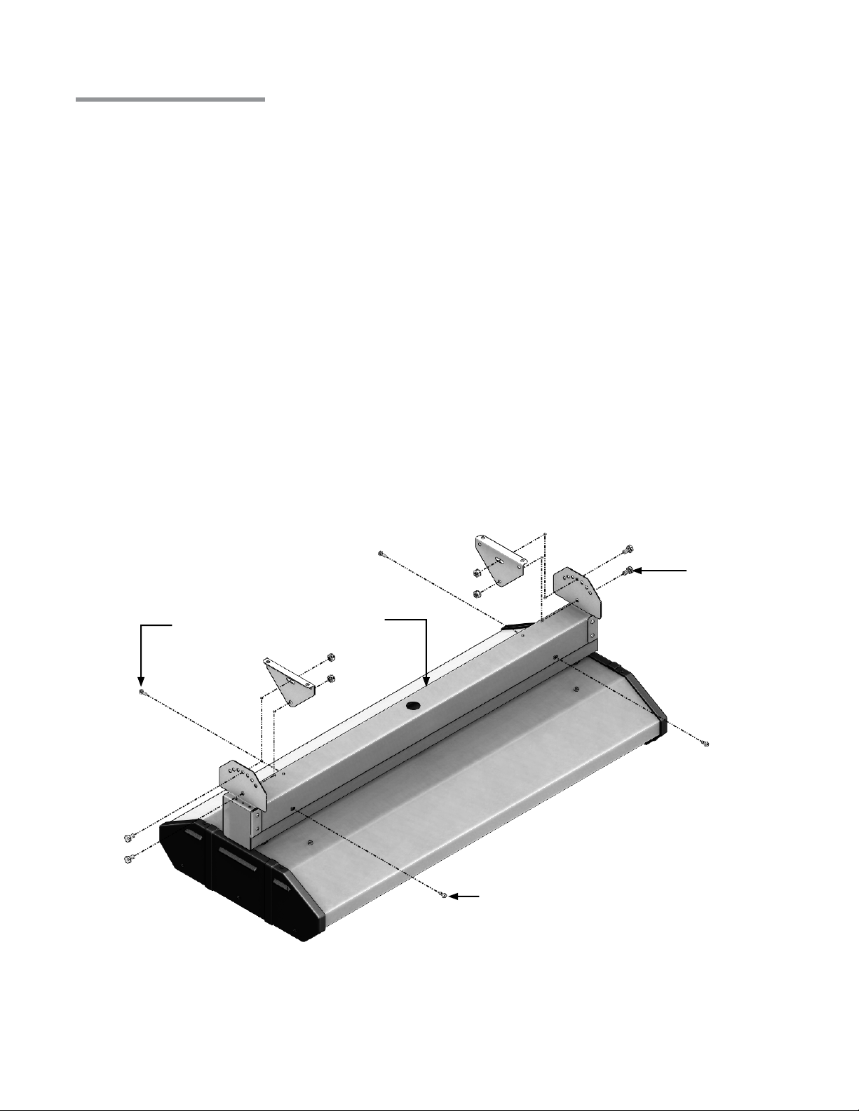
Attach the mounting brackets to the top wire raceway. On each end, place (1) ⁄” x ⁄” bolt through the
1
bottom hole of the mounting bracket and through the bottom hole of the top wire raceway. Place (1) ⁄”
lock nut on each bolt. Do not tighten completely. Refer to Figure 2.4.
NOTE: The mounting brackets are NOT required for chain suspension.
Adjust wire raceway to desired mounting angle.
2
On each side, place (1) ⁄” x ⁄” bolt through slot in the mounting bracket and the hole in the top wire
3
raceway. Place (1) ⁄” lock nut on each bolt and tighten.
Tighten lock nuts from Step 1.
4
Hook heater body into mounted wire raceway. Unit will hang freely by the “T” hinge, leaving both hands
5
free to wire unit. Refer to Figure 2.4.
Run supplied high temperature wires out to field supplied junction box. DO NOT make connections inside
6
the wire raceway.
Close wire raceway using the (4) #8-32 x ⁄” grounding screws provided in hardware pack.
7
Figure 2.4 • Top Channel Assembly
#8-32 x ⁄”
Screw
Wire Raceway
⁄” x ⁄” Bolt
14
#8-32 x ⁄” Grounding Screw
Page 15
MEL Series
!
2.0 Installation • Lamp Installation
Lamp Installation
CAUTION
Disconnect power prior to installing or replacing supplied quartz lamp(s). The elements can and should be
installed prior to mounting the heater.
Ensure appliance is OFF and is cool to the touch.
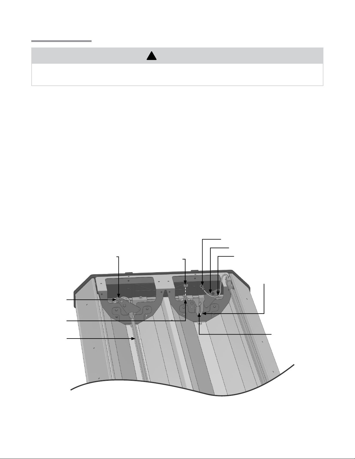
1
Remove both service access panels using a ⁄” nut driver.
2
Open lamp retainers by rotating the retainers on both sides of the unit (see Figure 2.5).
3
Position heating elements in “U” slots and firmly press the ceramic connector end into the clip(s), one
4
end at a time. Avoid handling the quartz glass as much as possible.
Remove the top element wire retaining nut. Slide the ring terminal over the bolt until it meets the bottom
5
retaining nut. Replace top retaining nut and torque to 15 in.-lbs. Do not overtighten.
Rotate the lamp retainer into closed position.
6
Repeat steps 3 through 6 until all heating elements have been installed.
7
After heating elements have been installed, the quartz glass should be wiped down with alcohol using a
8
clean cloth.
Reinstall the service access panels.
9
Figure 2.5 • Lamp Installation
Bolt
Top
Retaining Nut
Bottom
Retaining Nut
Element
Top Retaining
Nut
Ring Terminal
Lamp Retainer
Element Wire
“U” Slots
Ceramic lamp clips
must be secure in
holder.
NOTE: MEL series heaters are designed for use with quartz lamp infrared heating elements only. They are
NOT intended to be used with straight metal rod heating elements. Replace lamps with parts from Modine
only!
15
Page 16
2.0 Installation • Outdoor Applications • Electrical
!
!
MEL Series
Outdoor Applications
CAUTION
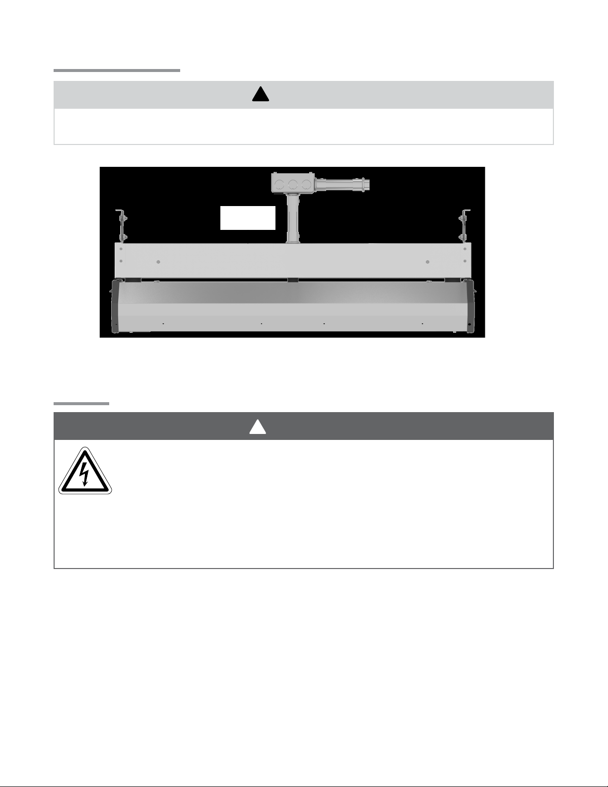
For totally exposed outdoor applications (not ceiling protected) ensure connections are made as illustrated
in Figure 2.6.
Figure 2.6 • Outdoor Application
6”
Minimum
NOTE: All conduit, conduit fittings, and junction boxes are field supplied. Must be NEMA Type 4X or
equivalent. Heater must be suspended from mounting brackets.
Electrical
WARNING
Electric Shock
Field wiring to the heater must be connected and grounded in accordance with national, state,
provincial, and local codes, and to the guidelines in the this manual. In the United States, refer
to the most current revisions to the ANSI/NFPA 70 Standard and in Canada, refer to the most
current revisions the CSA C22.1 Part I Standard.
Disconnect power to heater before servicing.
Failure to follow these instructions can result in death or electrical shock.
This fixture is equipped with high temperature silicone lead wires to make connections to branch circuit.
Remove the wire ties prior to making electrical connections.
Wiring connections should always be through one of the knockouts in the top wire raceway. Wire connections
must also be made outside of the top of the wire raceway. Consult the factory or a qualified electrician for
details on staging.
Supply wires must be a copper conductor type with a minimum size of 10 AWG suitable for at least 200°C.
The heater must be connected to the earthing conductor (green wire) installed by the factory.
Reference top of page 16 for use in outdoor applications.
16
Page 17
MEL Series
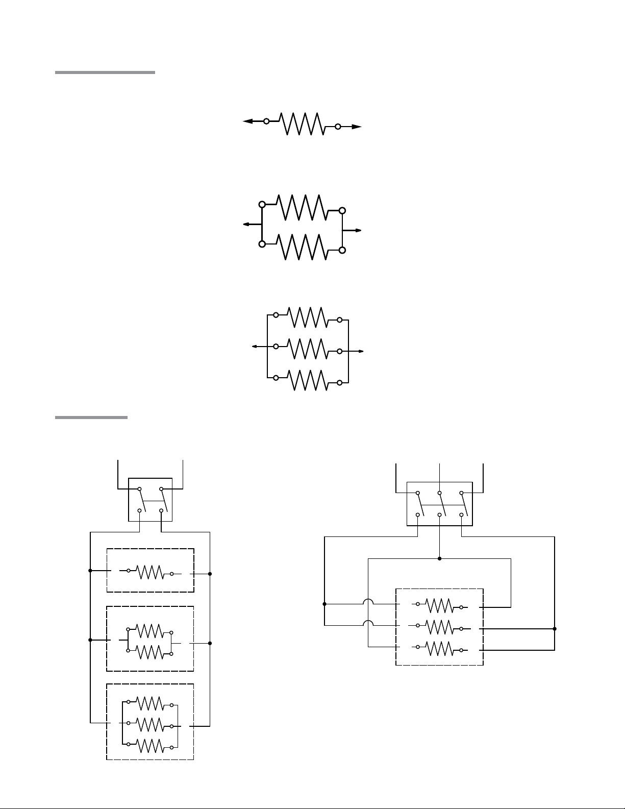
LAMP NO. 1
L1
L2
SINGLE LAMP UNIT
DOUBLE LAMP UNIT
TRIPLE LAMP UNIT
CONTROL
DEVICE
L1 L2
L1
L1
L1
L2/
N*
L2/
N*
L2/
N*
Wiring Diagrams
Figure 2.7 • Wiring Diagram for Units with 1 Lamp
Figure 2.8 • Wiring Diagram for Units with 2 Lamps
2.0 Installation • Wiring Diagrams
L1
Figure 2.9 • Wiring Diagram for Units with 3 Lamps
L1
Field Wiring
Figure 2.10 • Single Phase Service
Heaters are built as single phase.
LAMP NO. 1
LAMP NO. 2
LAMP NO. 1
LAMP NO. 2
LAMP NO. 3
L2
L2
Figure 2.11 • Three Phase Service
Field configured.
L1 L3
CONTROL
L2
DEVICE
TRIPLE LAMP UNIT
L1
*N for 120 V
L1
L2
L2
L3
L3
and 277 V
17
Page 18
3.0 Maintenance • Maintenance Log
MEL Series
3.0 Maintenance
The following should become a standard yearly procedure to obtain maximum operating eciency and
trouble-free operation.
During long periods of non-usage, remove or cover heater with a polyethylene bag and disconnect from power
supply. If further service to the heater is desired, contact your representative or the factory.
Clean reflector surface with a damp cloth.
1
Ensure heater is secure on all hanging points.
2
Maintain clearances to combustibles at all times. Immediately remove objects in violation of any of the
3
published clearances to combustibles.
Check electrical wires and connections for wear or any kind of damage.
4
Maintenance Log
Date Maintenance Performed Replacement Parts Required
18
Page 19
MEL Series
3.0 Maintenance • Troubleshooting Guide
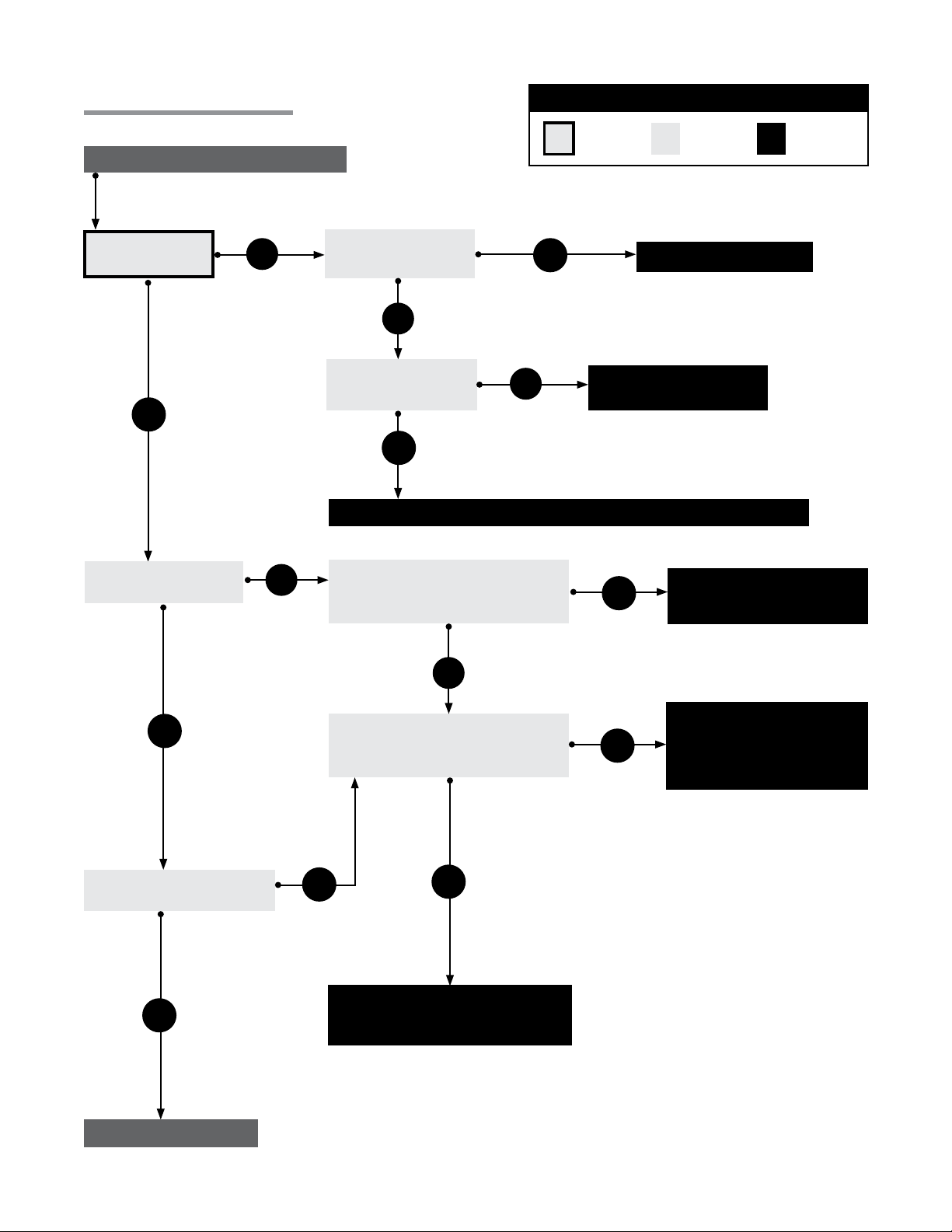
Troubleshooting Guide
Turn Heater on from power source.
Does the heating
lamp(s) turn on?
Yes
No
Key
Process
Question
Replace heating lamp(s).
Are the heating lamps
physically damaged?
Start
Question
Yes
No
Are the heating lamps
wired as indicated in
the manual?
No
Rewire lamps as indicated
in this manual.
Yes
Find the source of the electrical problem between panel and heater.
Corrective
Action
Is there a sucient
amount of heat?
Yes
Is there too much heat?
No
No
Is the supply voltage correct for the
model type on the rating label?
Yes
Is the heater mounted within the
recommended height?
Yes
Mount heater within the
recommended mounting heights.
No
No
Yes
Supply correct voltage.
Heater size and/or quantity of
heaters, may be incorrect for
application.
Troubleshooting ends.
19
Page 20
3.0 Maintenance • Heater Assembly Components
Heater Assembly Components
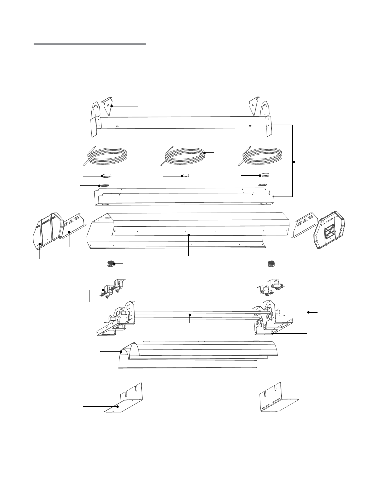
For complete information on MEL series replacement parts, contact your installation contractor.
Figure 3.1 • Components
80128
80129
80130
80131
80132 80133
80134
80132
MEL Series
80136
80137
80138
80147
80148
80158
80168
80141, 80142, 80143
80151, 80152, 80153
80161, 80162, 80163
80157
80167
80135
80140
80150
80160
80134
80144, 80145, 80146
80154, 80155, 80156
80164, 80165, 80166
80116–80127
80139
80149
80159
20
Page 21
MEL Series
3.0 Maintenance • Parts List
Parts List
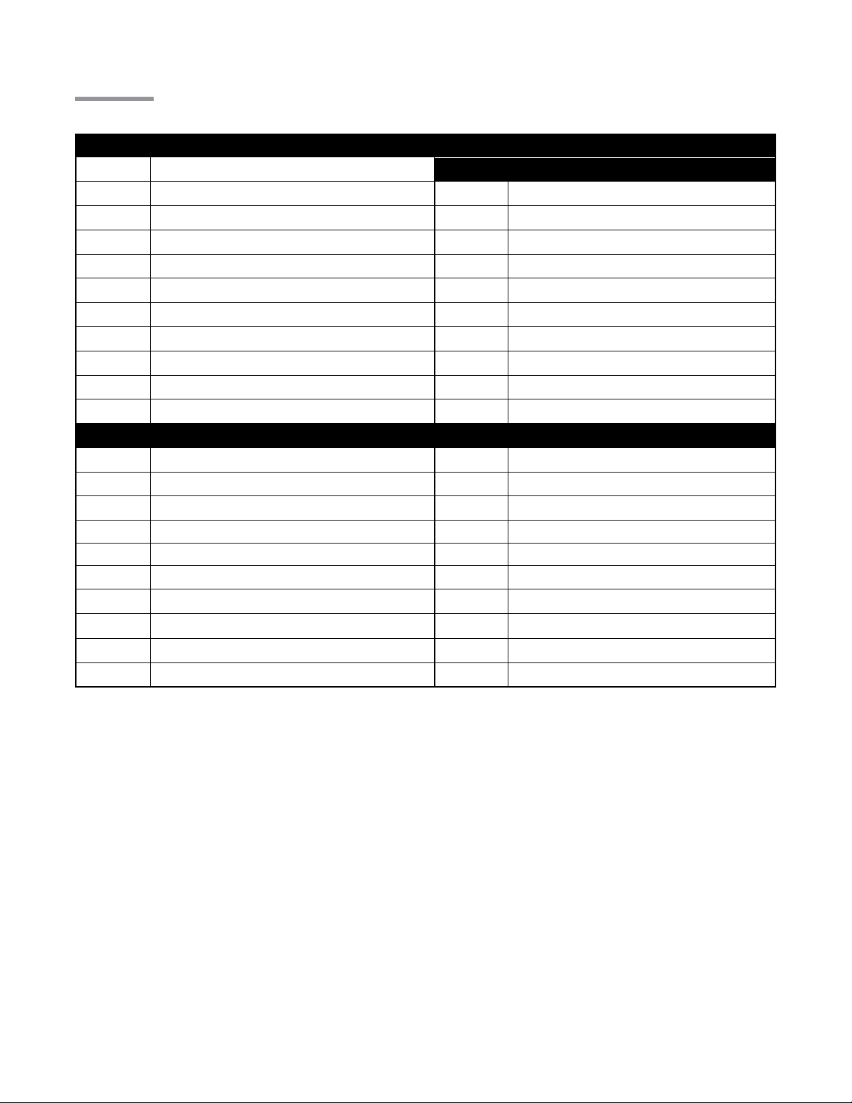
Chart 3.1 • General Parts
Part No. Description Part No. Description
80128 Mounting Brackets (set of 2) Double Element Model-Specific Parts
80129 12 Gauge Wire Length for 33” (specify color) 80149 Chassis Assembly with Lamp Stopper
80130 12 Gauge Wire Length for 24” (specify color) 80150 Service Access Panel - Vented
80131 12 Gauge Wire Length for 46” (specify color) 80151 Reflector, 24” Model
80132 Large Rubber Spacer (End - 2 per heater) 80152 Reflector, 33” Model
80133 Small Rubber Spacer (Center) 80153 Reflector, 46” Model
80134 Wire Bushing 80154 Shell Assembly, 24” Model
80135 Element Connector Assembly 80155 Shell Assembly, 33” Model
80136 Wire Raceway Assembly, 24” Model 80156 Shell Assembly, 46” Model
80137 Wire Raceway Assembly, 33” Model 80157 Rain Shield - Vented
80138 Wire Raceway Assembly, 46” Model 80158 Nylon End Panel
Single Element Model-Specific Parts Triple Element Model-Specific Parts
80139 Chassis Assembly with Lamp Stopper 80159 Chassis Assembly with Lamp Stopper
80140 Service Access Panel - Vented 80160 Service Access Panel - Vented
80141 Reflector, 24” Model 80161 Reflector, 24” Model
80142 Reflector, 33” Model 80162 Reflector, 33” Model
80143 Reflector, 46” Model 80163 Reflector, 46” Model
80144 Shell Assembly, 24” Model 80164 Shell Assembly, 24” Model
80145 Shell Assembly, 33” Model 80165 Shell Assembly, 33” Model
80146 Shell Assembly, 46” Model 80166 Shell Assembly, 46” Model
80147 Rain Shield - Vented 80167 Rain Shield - Vented
80148 Nylon End Panel 80168 Nylon End Panel
21
Page 22
3.0 Maintenance • Parts List
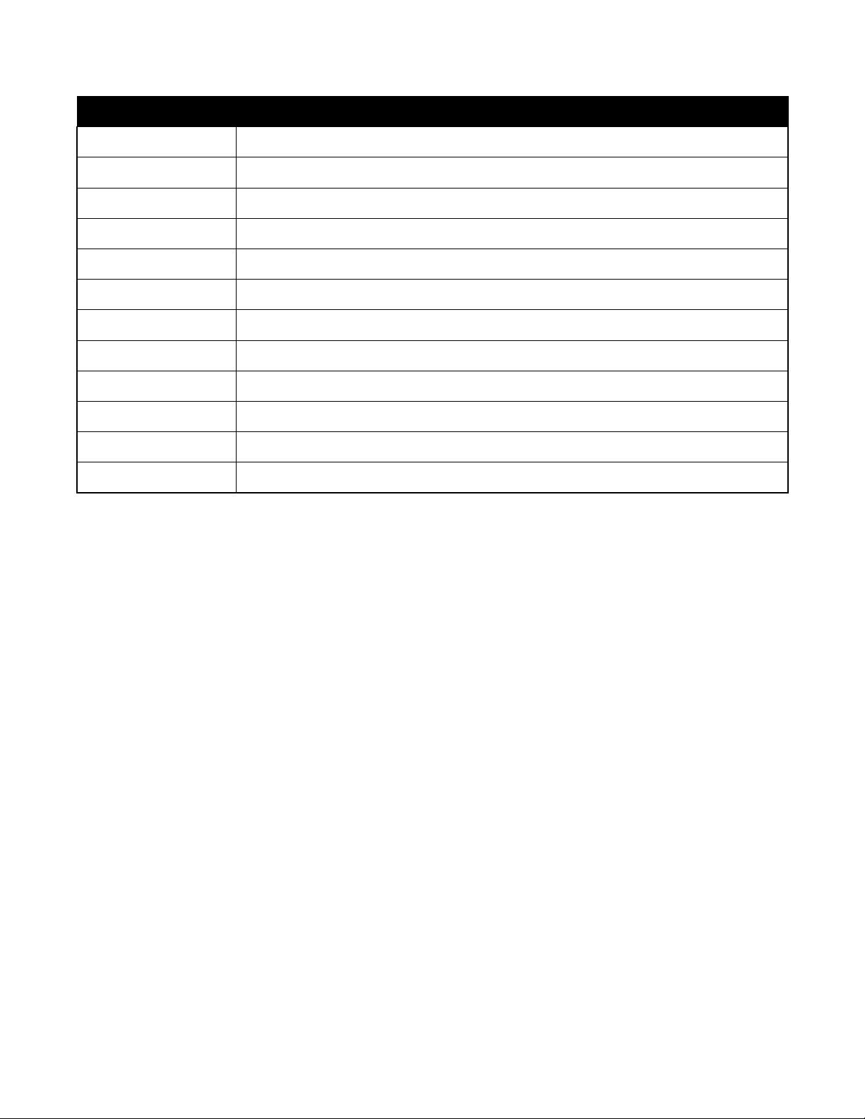
Chart 3.2 • Elements
Part No. Description
80116 120 V, 1360 W, 24” Long
80117 208 V, 1360 W, 24” Long
80118 240 V, 1360 W, 24” Long
80119 277 V, 1360 W, 24” Long
80120 480 V, 1360 W, 24” Long
80121 208 V, 2125 W, 33” Long
80122 240 V, 2125 W, 33” Long
80123 277 V, 2125 W, 33” Long
80124 480 V, 2125 W, 33” Long
80125 277 V, 3200 W, 46” Long
80126 480 V, 3200 W, 46” Long
MEL Series
80127 575 V, 3200 W, 46” Long
22
Page 23

MEL Series
WARRANTY
Heating and Indoor Air Quality Products
This Warranty (the “Warranty”) shall apply to Products (as
dened below) sold by Modine Manufacturing Company, a
Wisconsin corporation (“Seller”) to you (“Buyer”).
Seller hereby warrants that during the Applicable Warranty
Period (as dened below) its Products shall be free from
defects in material and factory workmanship under normal
use and service, subject to the EXCLUSIONS described
below and according to the terms outlined in this Warranty.
If Seller receives written notice of a breach of this Warranty
prior to the end of the Applicable Warranty Period (which
such notice shall include the model and serial numbers of
the Product, as well as the date and a reasonably detailed
description of the Product’s alleged failure), Buyer shall with
Seller’s prior written approval, return the applicable Product or
component thereof to Seller with shipping charges prepaid; if
upon examination by Seller such Product or component
thereof is disclosed to have been defective, then Seller will,
without charge to Buyer, at Seller’s option, either repair the
Product, replace defective parts in the Product, or oer an
entire replacement unit of the Product; provided that the
warranty period for a Product that has been repaired or
provided with replacement parts shall not extend beyond the
original Applicable Warranty Period, nor shall any replacement
parts provided for a Product be under any warranty beyond
the original Applicable Warranty Period for the Product;
similarly, if Seller provides an entire replacement unit of the
Product, the warranty period for the replacement unit is limited
to the remainder of the original Applicable Warranty Period.
Seller shall have no responsibility for installation, service, eld
labor, shipping, handling, or other costs or charges, except
as expressly provided in this Warranty. Buyer shall have no
remedy hereunder for any defective part returned without
proper written authorization from Seller, as described
above.
For purposes of this Warranty and subject to the exclusions
described below, the term “Products” shall mean parts or
equipment manufactured by Seller, sold to Buyer pursuant to a
purchase contract between Buyer and Seller (most often
initiated by a purchase order issued by Buyer and accepted by
Seller), and expressly described in such contract. The term
“Products” shall not include third-party parts or equipment
furnished by Seller, except that, to the extent assignable,
Seller will assign to Buyer the benets (together with all
limitations and exclusions) of the thirdparty manufacturer’s
warranty for such parts or equipment. This Warranty extends
only to the original purchase contract between Buyer and
Seller and is nontransferable, except that this Warranty may
be assigned to an Authorized End User (as dened below). All
replaced parts or equipment shall become Seller’s property.
For purposes of this Warranty, the term “Applicable Warranty
Period” shall mean the warranty period set forth in the table
below for each type or class of Product described on the table;
provided that, when the Product is to be used as a component
part of equipment manufactured by Buyer, the Applicable
Warranty Period shall be limited to one (1) year after the date
of shipment from Seller, notwithstanding anything in the table
below to the contrary. For purposes of this Warranty, the term
“Authorized End User” shall mean any third-party that
purchases the Product directly or indirectly from Buyer for the
Authorized End User’s own use upon the rst installation of
the Product and not for resale.
BUYER HEREBY ACKNOWLEDGES THAT ITS REMEDIES
FOR BREACH OF THIS WARRANTY, EXCLUSIVE OF ALL
OTHER REMEDIES PROVIDED BY LAW, ARE LIMITED AS
DESCRIBED ABOVE.
EXCLUSIONS AND LIMITATIONS: This Warranty is subject to
the following exclusions and limitations:
The term “Products” shall not include and this Warranty shall not
apply to any of the following items: refrigerant gas, belts, lters,
fuses and other items consumed or worn out by normal wear and
tear.
In addition, this Warranty shall not apply to:
(1) Products or components thereof that are damaged or adversely
aected by conditions beyond Seller’s control, including but not
limited to polluted or contaminated or foreign matter contained in the
air or water utilized for heat exchanger (condenser) cooling or if the
failure of the part is caused by improper air or water supply, or
improper or incorrect sizing of power supply;
(2) Any Products or components thereof which have been repaired or
altered outside the factory of Seller in any way, or otherwise subject
to unauthorized repairs or alterations, so as, in the judgment of
Seller, to aect the Product’s durability or performance;
(3) Materials or labor of any kind not furnished by Seller, or any charges
for any such labor or materials, whether such labor, materials or
charges thereon are due to replacement of parts, adjustments,
repairs, or any other work done by any party other than Seller;
(4) Labor or other costs incurred for diagnosing, repairing, removing,
installing, shipping, servicing, or handling of either defective or
replacement parts;
(5) Any Products removed from their original location for reinstallation in
another location;
(6) Any Products or components thereof which have been operated,
maintained, or serviced contrary to Seller’s written installation,
operation, and/or servicing instructions or owner’s manual;
(7) Damages resulting from operation with an inadequate or interrupted
supply of air or water;
(8) Any Products or components thereof which have been subjected to
misuse, negligence, faulty installation, improper servicing, accident,
excessive thermal shock, excessive humidity, physical damage,
impact, abrasion, improper operation, or other operating conditions
in excess of or contrary to those for which such equipment was
designed;
(9) With respect to gas-red or oil-red units, any Products or
components thereof if the input to the Product exceeds the rated
input (as indicated on the Product’s serial plate) by more than ve
percent (5%);
(10) Any Products or components thereof which, in the judgment of
Seller, have been installed in a corrosive atmosphere, marine, or
coastal application, subjected to corrosive uids or gases, or
damaged or adversely aected by the eects of the physical or
chemical properties of water or steam or other liquids or gases used
in the Products or any component thereof;
(11) Damage or failure to start resulting from improper voltage
conditions, blown fuses, open circuit breakers, or other inadequacy
or interruption of electrical service or fuel supply; or
(12) Any Products or components thereof from which the serial number
has been altered, defaced or removed.
23
Page 24
MEL Series
BUYER AGREES THAT THE WARRANTIES AND
REMEDIES DESCRIBED HEREIN ARE THE ONLY
WARRANTIES AND REMEDIES PROVIDED BY SELLER
WITH RESPECT TO THE PRODUCTS AND TO THE
MAXIMUM EXTENT PERMITTED UNDER APPLICABLE
LAW SHALL BE IN LIEU OF AND EXCLUSIVE OF ALL
OTHER WARRANTIES AND REMEDIES WHATSOEVER,
EITHER EXPRESS OR IMPLIED, WHETHER ARISING
FROM LAW, COURSE OF DEALING, USAGE OF TRADE,
OR OTHERWISE, INCLUDING BUT NOT LIMITED TO
WARRANTIES OF MERCHANTABILITY, FITNESS FOR A
PARTICULAR PURPOSE, AND NON-INFRINGEMENT,
EACH OF WHICH SELLER HEREBY EXPRESSLY
DISCLAIMS. SELLER NEITHER ASSUMES (NOR HAS
AUTHORIZED ANY PERSON TO ASSUME) ANY OTHER
WARRANTY OR LIABILITY IN CONNECTION WITH ANY
PRODUCTS. REPRESENATATIONS AND CONDITIONS,
EXPRESS OR IMPLIED BY STATUTE, TRADE USAGE, OR
OTHERWISE, ARE EXCLUDED AND WILL NOT APPLY TO
THE PRODUCTS UNDER THIS WARRANTY, EXCEPT FOR
WARRANTIES WHICH BY LAW CANNOT BE EXCLUDED
OR LIMITED. Without limiting the foregoing, Seller makes no
and specically disclaims all representations and/or warranties
COMPONENT APPLICABLE MODELS
Gas Fired Unit Heaters with
Tubular Style Heat Exchangers
(e.g. HD, HDS, PTS, BTS, etc.)
Gas Fired Unit Heaters with
Clam-Shell Style Heat
Heat Exchangers
and/or Coils
Exchangers
(e.g. PDP, BDP, etc.)
that the Products will detect the presence of, or eliminate, prevent, treat,
or mitigate the spread, transmission, or outbreak of any pathogen,
disease, virus, or other contagion, including but not limited to COVID19.
BUYER AGREES THAT IN NO EVENT WILL SELLER BE LIABLE FOR
COSTS OF PROCESSING, LOST REVENUES OR PROFITS, INJURY
TO GOODWILL, OR ANY OTHER SPECIAL, CONSEQUENTIAL, OR
INCIDENTAL DAMAGES OF ANY KIND RESULTING FROM THE
PURCHASE OF THE PRODUCTS, OR FROM BUYER’S USE OF ANY
PRODUCT, WHETHER ARISING FROM BREACH OF WARRANTY,
NONCONFORMITY TO ORDERED SPECIFICATIONS, DELAY IN
DELIVERY, OR ANY OTHER LOSS SUSTAINED BY THE BUYER.
OPTIONAL SUPPLEMENTAL WARRANTY
Buyer may purchase from Seller a supplemental warranty with respect to
Products which shall extend the Applicable Warranty Period as set forth
in the express terms and conditions described in the supplemental
warranty agreement. Such supplemental warranty terms may include an
additional four (4) years on certain compressors, an additional ve (5)
years “all parts” warranty, an additional four (4) or nine (9) years on
certain heat exchangers, and/or such additional supplemental warranty
terms as Seller chooses to make available to its customers from time to
time.
APPLICABLE WARRANTY PERIOD
(WHICHEVER OCCURS FIRST)
Aluminized or
Stainless Steel
Aluminized Steel
(not in high-humidity
applications)
Aluminized Steel
(in high-humidity
applications)
Time from Date of First
Benecial Use by
Buyer or Authorized
End User
10 YEARS 126 MONTHS
10 YEARS
(must be Stainless Steel in
high-humidity applications)
1 YEAR 18 MONTHS
Time from Date of
Shipment from
Seller
126 MONTHS
Stainless Steel 10 YEARS 126 MONTHS
Low Intensity Infrared Units 5 YEARS 66 MONTHS
Indoor and Outdoor Duct Furnaces and System Units,
Steam/Hot Water Units, Oil-Fired Units, Electric Units,
Cassettes, Vertical Unit Ventilators, Geothermal Units
Burners and Elements
High Intensity Infrared and Electric Infrared Units 1 YEAR 18 MONTHS
Compressors
Sheet Metal Parts All Products 1 YEAR 18 MONTHS
Components excluding
Heat Exchangers, Coils,
Condensers, Burners,
Sheet Metal
As Modine Manufacturing C ompany has a continuous product improvement program, it reser ves the right to change design and specications without notic e.
© Modine Manufacturin g Compa ny 2023
Low Intensity Infrared Units 2 YEARS 30 MONTHS
Condensing Units for Cassettes 5 YEARS 66 MONTHS
Vertical Unit Ventilators, Geothermal Units 1 YEAR 18 MONTHS
All Products 2 YEARS 30 MONTHS
24
1 YEAR 18 MONTHS
Modine Manufacturing Company
1500 DeKoven Avenue
Racine, WI 53403
Phone: 1.800.828.4328 (HEAT)
www.modinehvac.com
 Loading...