

GAS-FIRED SEPARATED
COMBUSTION UNIT HEATERS
MODEL HDS MODEL HDC
6-175.9 • APRIL, 2018
MODEL PTS / BTS

TABLE OF CONTENTS
!
!
Modine’s separated combustion unit heaters are designed for
the heating requirements of commercial and industrial buildings
with select models available for residential garage heating as
well. The separated combustion units draw combustion air from
outside to ensure that the unit will always have plenty of fresh,
clean air for combustion, reducing common concerns about
dusty, dirty, humid, or negative space pressure applications.
In addition, by drawing the combustion air from the outside,
the overall heating efficiency is increased.
With 13 propeller and 11 blower model sizes available, the
units cover a wide variety of applications with input ranges
from 30,000 to 400,000 Btu/Hr in either natural or propane
gas. This catalog describes the design benefits, construction
features, performance data, unit selection procedure, and
the optional and accessory devices available.
Table of Contents Page
Design Features - All Models................................................................................3-5
General Performance Data - Propeller Models HDS/PTS ........................................................... 6
General Performance Data - Blower Models HDC/BTS ............................................................ 7
Blower Performance Data - Blower Model HDC .................................................................. 8
Blower Performance Data - Blower Model BTS.................................................................9-11
Gas Control Data - All Models ...............................................................................12
Field Installed Accessories .................................................................................. 13
Downturn Hood Performance Data - Propeller Models HDS/PTS.................................................... 14
Downturn Hood Performance Data - Blower Model HDC/BTS ...................................................... 15
Unit Selection ..........................................................................................16-17
Dimensional Data - Models HDS/HDC......................................................................... 18
Dimensional Data - Model PTS .............................................................................. 19
Dimensional Data - Model BTS .............................................................................. 20
Specifications - All Models ................................................................................21-22
Model Nomenclature - All Models ............................................................................23
WARNING
Do not locate ANY gas-fired unit in areas where chlorinated,
halogenated or acid vapors are present in the atmosphere.
As Modine Manufacturing Company has a continuous product improvement program, it reserves the right to change design and specifications without notice.
The Modine Breeze® AccuSpec is the fastest way to generate performance data based
on actual job conditions. The Breeze® AccuSpec program is a web-based sizing and selection
program. The program provides a series of step-by-step questions that allow for the easy
configuration of Modine products. After a model has been configured, the program can
generate Submittal Schedules, Submittal Data (including performance and dimensional
drawings), and Specifications.
2
WARNING
Appliances must not be installed where they may be exposed
to a potentially explosive or flammable atmosphere.
6-175.9

DESIGN FEATURES - ALL MODELS
Separated Combustion Unit Heaters, 30-125MBH
For residential, commercial or industrial applications that require
a low profile unit, Modine offers the Hot Dawg®. Capable of
being installed just one inch below the ceiling, the superior
quality of the Hot Dawg makes it a preferred choice for a
variety of applications, including garages and workshops.
Figure 3.1 - Hot Dawg
Propeller Unit Heater
Model HDS Model HDC
Figure 3.2 - Hot Dawg
Blower Unit Heater
Table 3.1 - Standard Features and Factory Options j
Feature
Aluminized steel cabinet (gauge indicated) 22 ga. 22 ga. 20 ga. 20 ga.
Low profile casing design • •
Baked-on polyester powder paint for durability and corrosion resistence • • • •
Adjustable air-deflector blades • • • •
Fans engineered for quiet operation • • • •
Totally enclosed fan/blower motors for maximum durability (model sizes 100 and above)
Fingerproof fan guard (optional on PTS units) • • •
Two L-shaped mounting brackets (optional on sizes 100/125) • •
Cabinet and Air Mover
Multi-tap 3-speed motors, certified to 0.8” W.C. external static pressure •
Adjustable motor sheaves, certified to 0.7” W.C. external static pressure •
82% thermally efficient • • • •
Aluminized steel heat exchanger (409 stainless steel optional) • • • •
Heat
j See page 13 for Field Installed Accessories
Tubular heat exchanger for superior durability • • • •
Exchanger
and Burner
In-shot burner on each heat exchanger tube for reliable performance, ease of
serviceability and low sound level on flame ignition/extinction
ETL certification for commericial and industrial use in the US and Canada • • • •
ETL certification for residential use in the US and Canada • •
Factory-installed power exhauster • • • •
Controls for natural gas (propane optional) • • • •
Single stage gas controls (two stage optional) • • • •
High limit safety control • • • •
Differential pressure switch for proof of venting • • • •
Flame roll-out safety switch • •
Controls
Direct spark ignition with continuous retry control system • • • •
Control terminal board and low voltage terminal connections • • • •
Gas control step down transformer with 24V gas controls • • • •
Fan delay timer • • • •
Factory installed on/off toggle switch • • • •
Separated Combustion Unit Heaters, 150-400MBH
For commercial or industrial applications that require higher input
ratings, the PTS/BTS is available in ratings that range from
150,000 to 400,000 Btu/Hr in either natural or propane gas.
Figure 3.3 Propeller Unit Heater
Model PTS Model BTS
HDS HDC PTS BTS
• • •
• • • •
Figure 3.4 Blower Unit Heater
Model
6-175.9
3

DESIGN FEATURES - ALL MODELS
Figure 4.1 - Factory Mounted Standard and Optional Features
6
4
10
11
1
2
3
5
Models HDS/HDC (30-125MBH) Models PTS/BTS (150-400MBH)
9
6
7
j Power Exhauster (STD)
All units are supplied with a round vent pipe and
combustion air inlet pipe connections.
k Pressure Switch (STD)
An automatic reset vent pressure switch is supplied on
all units and is designed to prevent operation of the main
burner in the event there is restricted venting of flue
products. This restriction may occur due to an improper vent
diameter, long vent runs, un-approved vent terminal, high
winds, high negative pressure within space, etc. After the
cause of the restriction has been corrected, the pressure
switch will reset automatically.
l Integrated Direct Spark Control Board (STD)
The integrated direct spark ignition control combines all
furnace control functions. The integrated board provides
digital control of the air mover, inducer, ignition, gas valve
and flame sense as well as monitoring the safety circuit at
all times. The board includes LED diagnostics for trouble
shooting and a fused power supply.
m Gas Valve - (See Table 12.2)
a) Single Stage Gas Valve - (STD)
The main gas valve is factory installed on the unit
heater gas train. The main gas valve provides regulator,
main gas, and manual shutoff functions. The valve is
redundant and provides 100% shut off.
b) Two Stage Gas Valve - (OPT)
The two-stage gas valve is factory installed on the unit
heater gas train. The two stage gas valve provides the
regulator, main gas (100% and 50% fire), and manual
shutoff functions. The valve is redundant and provides
100% shut off.
8
11
1
10
8
2
5
4
3
9
8
13
n Control Step Down Transformer - (STD)
The control step down transformer is located in the
electrical junction box. The transformer is used to step
down from 115V to 24V for the gas controls, fan delay
relay, field supplied motor starter, etc. An additional field
installed transformer is required if the supply voltage
is 208V, 230V, 460V, or 575V. To determine the control
transformer supplied as well as any accessory/field supplied
transformers required, refer to Table 12.1
o Flame Sensor (hidden) - (STD)
Remote flame sensor verifies ignition of all burners,
monitors the flame signal and communicates with the
integrated circuit board.
p Flame Roll Out Switch (HDS/HDC models only) - (STD)
Flame roll out switches are mounted near the burners and
will shut off the gas supply in the event of an unsafe flame
roll out condition.
q High Limit Switch (hidden) - (STD)
The limit control is mounted in the air stream and will shut
off the gas supply in the event of overheating.
r Direct Spark Igniter (hidden) - (STD)
Provides spark for direct ignition of the burners.
s Gas Pipe Connection - (STD)
Easy access to factory installed gas pipe connection
stubbed to outside of unit casing.
On/Off Toggle Switch - (STD)
Factory installed on/off toggle swicth mounted to outside of
unit casing.
4
6-175.9

DESIGN FEATURES - ALL MODELS
Figure 5.1 - Factory Mounted Standard and Optional Features
1
17
11
Finger Proof Fan Guard (STD thru 125, OPT 150-400)
Propeller units may be equipped with an optional finger
proof fan guard for added protection. The finger proof
fan guard is installed at the factory in place of the standard
fan guard.
Blower Motor - (STD for HDC/BTS Models)
The blower motor is factory installed on the blower housing.
Blower motors smaller than 3 HP are factory installed on the
blower housing. Motors 3 HP and above are shipped loose
for field installation to prevent damage during shipment.
For blower models 60-125, the blower is direct driven by a
3-speed motor. For blower models 150-400, the blower motor
is supplied with an adjustable sheave that can be used to
increase/decrease the blower RPM, and the blower motor
can be provided in a variety of supply voltages and motor
horsepowers.
181(outlet) (inlet)
19
Horizontal Air Deflector Blades (STD)
Factory mounted on the discharge of the unit, the blades can
be adjusted to provide horizontal (up and down) delivery control
of the heated air. Vertical deflector blades are available as a
field installed accessory.
Blower Enclosure (OPT for HDC/BTS Models)
Filter Rack (OPT for HDC/BTS Models)
Provides filtration of air to be heated. Must include Blower
Enclosure accessory.
20
6-175.9
5

GENERAL PERFORMANCE DATA - MODELS HDS & PTS
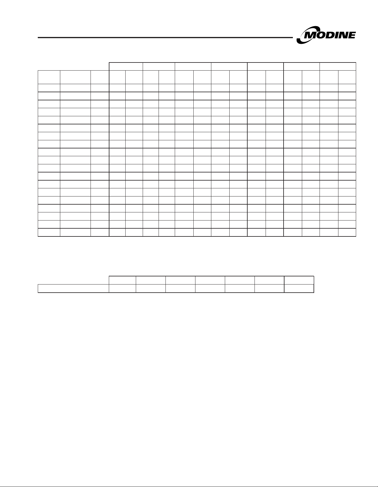
Table 6.1 - Propeller Unit Model HDS and PTS General Performance Data
Model HDS Sizes Model PTS Sizes
30 45 60 75 100 125 150 175 200 250 300 350 400
Btu/Hr Input j
Btu/Hr Ouput j
Entering Airflow (CFM)
@ 70°F
Outlet Velocity (FPM) 523 725 653 769 565 747 711 607 643 721 824 748 851
Air Temp. Rise (°F) 44 46 45 48 50 47 53 48 52 47 50 50 51
Max. Mounting
Height (Ft.) k
Heat Throw (Ft.) @
Max Mtg Ht k
Motor Type l
Motor HP 1/15 1/15 1/12 1/12 1/6 1/8 1/6 1/6 1/3 1/3 1/2 1/2 3/4
Motor RPM 1550 1550 1625 1625 1050 1625 1075 1075 1075 1075 1075 1125 1125
j Ratings shown are for elevations up to 2,000 ft. For elevations above 2,000 feet, ratings should be reduced at the rate of 4% for each 1,000 feet above sea level. (In
Canada see rating plate.) Reduction of ratings requires use of a high altitude kit.
k Data taken at 55°F air temperature rise. At 65°F ambient and unit fired at full-rated input. Mounting height as measured from bottom of unit, and without deflector
hoods.
l All motors used are produced, rated and tested by reputable manufacturers in accordance with NEMA standards and carry the standard warranty of both the motor
manufacturer and Modine. Motors on model sizes 100 and above are totally enclosed (Model size 75 and below are open drip proof) and all single phase motors have
built in thermal overload protection.
30,000 45,000 60,000 75,000 100,000 125,000 150,000 175,000 200,000 250,000 300,000 350,000 400,000
24,600 36,900 49,200 61,500 82,000 102,500 123,000 143,500 164,000 205,000 246,000 287,000 328,000
505 720 990 1160 1490 1980 2140 2725 2870 3995 4545 5280 5995
10 10 12 14 12 16 15 14 15 18 19 18 21
25 27 36 38 42 56 51 50 53 62 69 65 74
SP SP PSC PSC PSC PSC PSC PSC PSC PSC PSC PSC PSC
Table 6.2 - Propeller Unit Model HDS and PTS Operating Electrical Data m
Supply
Voltage
115V
1 Phase
208V
1 Phase
230V
1 Phase
208V
3 Phase
230V
3 Phase
460V
3 Phase
575V
3 Phase
m Amp draw data shown is operating amp draw at incoming power. For units that use a field installed accessory step-down transformer as noted, the amp draw shown is
the primary side operating amp draw. For sizing of circuit protection for equipment with transformers, please refer to the National Electric Code.
Power Code
01 (115V)
01 (115V) with
Transformer
01 (115V) with
Transformer
01 (115V) with
Transformer
01 (115V) with
Transformer
01 (115V) with
Transformer
01 (115V) with
Transformer
30 45 60 75 100 125 150 175 200 250 300 350 400
Motor Amps 2.40 2.40 1.95 1.95 2.50 2.20 2.50 2.50 4.60 4.60 7.00 7.00 8.80
Total Amps 3.75 3.75 3.3 3.3 5.05 4.75 5.05 5.05 7.15 7.15 8.11 8.65 10.45
Transformer kVA n/a n/a n/a n/a n/a n/a n/a n/a n/a n/a n/a n/a n/a
Transformer kVA 0.50 0.50 0.50 0.50 1.00 1.00 1.00 1.00 1.00 1.00 1.00 1.00 1.50
208V Total Amps 2.05 2.05 1.80 1.80 2.79 2.63 2.79 2.79 4.20 3.95 4.48 4.78 5.78
Transformer kVA 0.50 0.50 0.50 0.50 0.75 0.75 0.75 0.75 1.00 1.00 1.00 1.00 1.50
230V Total Amps 1.85 1.85 1.63 1.63 2.53 2.38 2.53 2.53 3.80 3.58 4.06 4.33 5.23
Transformer kVA 0.50 0.50 0.50 0.50 0.75 0.75 0.75 0.75 1.00 1.00 1.00 1.00 1.50
460V Total Amps 0.93 0.93 0.81 0.81 1.26 1.19 1.26 1.26 1.90 1.79 2.03 2.16 2.61
Transformer kVA 0.50 0.50 0.50 0.50 0.50 0.50 0.50 0.50 0.50 0.50 0.50 0.50 0.50
575V Total Amps 0.74 0.74 0.65 0.65 1.01 0.95 1.01 1.01 1.52 1.43 1.62 1.73 2.09
Model HDS Sizes Model PTS Sizes
6
6-175.9

GENERAL PERFORMANCE DATA - MODELS HDC & BTS
Table 7.1 - Blower Unit Model HDC and BTS General Performance Data
Model HDC Sizes Model BTS Sizes
60 75 100 125 150 175 200 250 300 350 400
Btu/Hr Input j
Btu/Hr Ouput j
Entering Airflow
Range (CFM)
Outlet Velocity
(FPM)
Air Temp. Rise
(°F)
Max. Mounting
Height (Ft.) k
Heat Throw (Ft.)
@ Max Mtg Ht k
Motor Type l
Motor HP 1/4 1/3 1/2 1/2 See Table 9.1
Motor RPM Max 1100
Table 7.2 - Blower Unit Model HDC and BTS Operating Electrical Data
Supply
Voltage
115V
115V
1 Phase Total Amps 7.05 8.45 12.05 12.05
1 Phase
208V
1 Phase
230V
1 Phase
208V
208V
3 Phase 208V Total Amps 3.87 4.64 6.66 6.66
3 Phase
230V
230V
3 Phase 230V Total Amps 3.50 4.20 6.03 6.03
3 Phase
460V
460V
3 Phase 460V Total Amps 1.75 2.10 3.01 3.01
3 Phase
575V
3 Phase
Power Code
01 (115V)
01 (115V) with
Transformer
01 (115V) with
Transformer
01 (115V) with
Transformer
01 (115V) with
Transformer
01 (115V) with
Transformer
01 (115V) with
Transformer
60,000 75,000 100,000 125,000 150,000 175,000 200,000 250,000 300,000 350,000 400,000
49,200 61,500 82,000 102,500 123,000 143,500 164,000 205,000 246,000 287,000 328,000
6351111
437-726
7941389
546-
908
1140-
2116
443-
781
1235-
2058
488-
773
1587-
2778
543-
903
1852-
3241
2116-
3704
2646-
4630
428-711 489-813 497-826 596-991 543-903 621-1032
40-70 40-70 35-65 45-75 40-70 40-70 40-70 40-70 40-70 40-70 40-70
7-13 7-16 8-19 8-17 9-21 8-18 9-21 10-22 11-26 11-26 13-29
20-45 24-57 27-68 27-59 33-75 28-65 32-74 34-78 40-94 39-90 44-102
P.S.C. P.S.C. P.S.C. P.S.C. T. E T. E T.E T.E T.E T. E T. E
Max
1100
Max
1100
Max
1100
1725 1725 1725 1725 1725 1725 1725
Model HDC Sizes Model BTS Sizes
60 75 100 125 150 175 200 250 300 350 400
Motor Amps 5.70 7.10 9.50 9.50
Transformer kVA n/a n/a n/a n/a
Transformer kVA 1.00 1.00 1.50 1.50
208V Total Amps 3.87 4.64 6.66 6.66
Transformer kVA 1.00 1.00 1.50 1.50
230V Total Amps 3.50 4.20 6.03 6.03
Transformer kVA 1.00 1.00 1.50 1.50
See Tables 7.3 through 7.5
Transformer kVA 1.00 1.00 1.50 1.50
Transformer kVA 1.00 1.00 1.50 1.50
Transformer kVA 1.00 1.00 1.50 1.50
575V Total Amps 1.40 1.68 2.41 2.41
3175-
5556
3704-
6481
4233-
7407
Table 7.3 - Blower Model BTS Motor Amp Draw m n
Supply Voltage
Motor HP 115V/1ph 230V/1ph 208V/3ph 230V/3ph 460V/3ph 575V/3ph
1/4 3.70 - - - - -
1/3 5.00 2.50 1.10 1.10 0.60 0.60
1/2 7.20 3.60 2.10 2.20 1.10 0.80
1 12.00 6.00 3.20 3.20 1.60 1.30
1-1/2 15.00 7.50 4.60 4.80 2.40 1.90
2 - - 6.00 5.80 2.90 2.30
3 - - 8.40 7.80 3.90 3.20
5 - - 13.60 12.30 6.20 5.10
Table 7.4 - Blower Model BTS Control Circuit Amp Draw m n
Supply Voltage
Model Size 115V/1ph 230V/1ph 208V/3ph 230V/3ph 460V/3ph 575V/3ph
150-250 2.55 1.28 1.41 1.28 0.64 0.51
300 1.11 0.56 0.61 0.56 0.28 0.22
350-400 1.65 0.83 0.91 0.83 0.41 0.33
6-175.9
Table 7.5 - Blower Model BTS
Accessory Transformer Size (kVA) o
Supply Voltage
208V 230V 460V 575V
Model Size 3 ph 1 or 3 ph 3 ph 3 ph
150-250 0.50 0.50 0.50 0.50
300-400 0.50 0.25 0.25 0.25
j Ratings shown are for elevations up to 2,000 ft. For elevations
above 2,000 feet, ratings should be reduced at the rate of 4% for
each 1,000 feet above sea level. (In Canada see rating plate.)
Reduction of ratings requires use of a high altitude kit.
k Data taken at 55°F air temperature rise. At 65°F ambient and unit
fired at full-rated input. Mounting height as measured from bottom
of unit, and without deflector hoods.
l All motors used are produced, rated and tested by reputable
manufacturers in accordance with NEMA standards and carry the
standard warranty of both the motor manufacturer and Modine.
Model HDC motors are open drip proof, while model BTS motors
are totally enclosed and all single phase motors have built-in
thermal overload protection.
m Amp draw data shown is operating amp draw at incoming power.
For units that use a field installed accessory step-down transformer
as noted, the amp draw shown is the primary side operating amp
draw. For sizing of circuit protection for equipment with
transformers, please refer to the National Electric Code.
n For BTS models, add the Motor Amp Draw and Control Circuit
Amp Draw to get the Total Unit Amp Draw.
o Transformers for blower models are typically smaller than those
used for propeller models, as the transformer is not needed for
the blower motor. Size 300-400 use a PSC power exhauster motor,
further reducing the required transformer size.
7

BLOWER PERFORMANCE DATA - MODEL HDC
Low Medium High
External Static Pressure (IN. WC)
Table 8.1 - Power Code Description - HDC Models
Power Code Unit Voltage HDC60 HDC75 HDC100 HDC125
01 115/60/1 1/4 HP 1/3 HP 1/2 HP 1/2 HP
Blower Speed Curves
Models (HDC 60-125)
70
65
60
55
50
45
Temperature Rise (Deg. F)
40
35
0.00
70
65
60
55
50
45
Temperature Rise (Deg. F)
40
35
0.00
0.20
0.10
External Static Pressure (IN. WC)
0.20
0.10
External Static Pressure (IN. WC)
HDC 60
0.30
0.40
HDC 75
0.30
0.40
0.50
0.50
0.60
0.60
0.70
0.70
635
684
741
808
889
988
1111
1270
794
855
926
1010
1111
1235
1389
1587
CFM
CFM
HDC 100
65
60
55
50
45
40
Temperature Rise (Deg. F)
35
0.00 0.10 0.20 0.30 0.40 0.50 0.60 0.70 0.80
HDC 125
75
70
65
60
55
50
Temperature Rise (Deg. F)
45
40
0.00 0.10 0.20 0.30 0.40 0.50 0.60 0.70 0.80
External Static Pressure (IN. WC)
1235
1323
1425
1543
1684
1852
2058
2315
1140
1235
1347
CFM
1481
1646
1852
2116
CFM
8
6-175.9
BLOWER PERFORMANCE DATA - MODEL BTS
Table 9.1 - Power Code Description - Blower Model BTS j
BTS150 BTS175 BTS200 BTS250 BTS300 BTS350 BTS400
Power
Code Voltage Phase HP Drive HP Drive HP Drive HP Drive HP Drive HP Drive HP Drive
01 115 1 1/4 230 - - - - - - - - - - - -
02 115/230 1 1/3 230 1/3 238 1/2 233 1/2 204 1 240 1 1/2 250 1 1/2 247
08 208-230/460 3 1/3 230 1/3 238 1/2 233 1/2 204 1 257 1 1/2 251 1 1/2 248
11 575 3 1/3 231 1/3 239 1/2 233 1/2 204 1 257 1 1/2 251 1 1/2 248
13 115/230 1 1/3 232 1/2 229 1 229 1 241 1 241 1 1/2 247 - -
19 208-230/460 3 1/3 232 1/2 229 1 259 1 258 1 258 1 1/2 248 2 177
22 575 3 1/3 233 1/2 229 1 259 1 258 1 258 1 1/2 248 2 177
24 115/230 1 1/2 229 1 175 1 175 1.5 23 1 1/2 243 1 1/2 252 - -
30 208-230/460 3 1/2 229 1 253 1 253 1.5 177 1 1/2 244 1 1/2 180 3 246
33 575 3 1/2 229 1 253 1 253 1.5 177 1 1/2 244 1 1/2 180 3 246
35 115/230 1 1 175 1 1/2 237 1 1/2 235 - - 1 1/2 23 - - - -
41 208-230/460 3 1 253 1 1/2 234 1 1/2 236 2 180 1 1/2 177 2 177 5 245
44 575 3 1 253 1 1/2 234 1 1/2 236 2 180 1 1/2 177 2 177 5 245
52 208-230/460 3 - - - - - - - - 2 177 2 180 - -
55 575 3 - - - - - - - - 2 177 2 180 - -
63 208-230/460 3 - - - - - - - - 3 112 3 246 - -
66 575 3 - - - - - - - - 3 11 2 3 246 - -
74 208-230/460 3 - - - - - - - - - - 5 245 - -
77 575 3 - - - - - - - - - - 5 245 - -
j For selection of correct Power Code, refer to the Tables on pages 10-11.
Table 9.2 - Filter Static Pressure Drop k
BTS150 BTS175 BTS200 BTS250 BTS300 BTS350 BTS400
Filter Static (“W.C.) 0.1 0.2 0.1 0.2 0.2 0.2 0.2
k For blower units with enclosure and filter, add the following static pressures to the static pressure determined by the system designer for total
external static pressure.
6-175.9
9

BLOWER PERFORMANCE DATA - MODEL BTS
Table 10.1 - Blower Model BTS 150-250 (40-55°F temp rise for 250 size unit) j k l
Model
ATR CFM HP RPM Drive Turns RPM Drive Turns RPM Drive Turns RPM Drive Turns RPM Drive Turns RPM Drive Turns RPM Drive Turns RPM Drive Turns HP
Size
40 2778 1 573 175 4.5 615 175 4.0 658 175 3.0 699 175 2.5 738 175 1.5 775 175 1.0 810 175 0.5 - - - 1
1/2
45 2469
1/3
50 2222
1/2 229 5.0 229 4.0 229 3.0 229 2.0 - - - - - - - - 1/2
1/4
1/3
55 2020
1/2 - - 229 5.0 229 3.5 229 2.5 229 1.5 229 1.0 - - - - 1/2
150
175
200
250
1/4
1/3
60 1852
1/2 - - - - 229 4.0 229 3.0 229 2.0 229 1.0 229 0.5 - - 1/2
1/4
1/3 230 4.0 232 4.5 232 3.0 232 2.0 232 1.0 - - - - - - 1/3
65 1709
1/2 - - - - 229 4.5 229 3.5 229 2.5 229 1.5 229 0.5 - - 1/2
1/4
1/3 230 5.0 232 5.0 232 3.5 232 2.5 232 1.0 232 0.0 - - - - 1/3
70 1587
1/2 - - - - 229 5.0 229 4.0 229 2.5 229 1.5 229 0.5 229 0.0 1/2
40 3241
1-1/2 - - - - - - 237 5.0 237 4.5 237 3.5 237 2.5 237 2.0 1-1/2
45 2881
1-1/2 - - - - - - - - - - 237 4.5 237 4.0 237 3.0 1-1/2
1/2
50 2593
1-1/2 - - - - - - - - - - - - 237 4.5 237 4.0 1-1/2
1/3
1/2 229 5.0 229 4.5 229 3.5 229 2.5 - - - - - - - - 1/2
55 2357
1-1/2 - - - - - - - - - - - - 237 5.0 237 4.5 1-1/2
1/3
1/2 - - 229 5.0 229 4.0 229 3.0 229 2.0 229 1.0 - - - - 1/2
60 2160
1-1/2 - - - - - - - - - - - - - - 237 4.5 1-1/2
1/3
1/2 - - - - 229 4.5 229 3.5 229 2.5 229 1.5 229 0.5 - - 1/2
65 1994
1-1/2 - - - - - - - - - - - - - - 237 5.0 1-1/2
1/3
70 1852
1/2 - - - - 229 5.0 229 3.5 229 2.5 229 1.5 229 1.0 - - 1/2
40 3704 1-1/2 715 235 3.5 741 235 2.5 770 235 2.0 - - - - - - - - - - - - - - - 1-1/2
45 3292
1-1/2 235 5.0 235 3.0 235 4.0 235 3.0 235 2.0 235 1.0 235 0.0 - - 1-1/2
50 2963
1-1/2 - - - - 235 5.0 235 4.0 235 3.0 235 2.0 235 1.5 235 0.5 1-1/2
1/2
55 2694
1-1/2 - - - - - - 235 5.0 235 4.0 235 3.0 235 2.0 235 1.0 1-1/2
1/2
60 2469
1-1/2 - - - - - - - - 235 5.0 235 4.0 235 3.0 235 2.0 1-1/2
1/2
65 2279
1-1/2 - - - - - - - - - - 235 4.5 235 3.5 235 2.5 1-1/2
1/2
70 2116
1-1/2 - - - - - - - - - - 235 5.0 235 3.5 235 2.5 1-1/2
1-1/2
40 4630
1-1/2 - - - - 23 4.5 23 3.5 23 2.5 23 1.5 23 0.5 - - 1-1/2
45 4115
1-1/2 - - - - - - 23 4.5 23 3.5 23 2.5 23 1.5 23 0.5 1-1/2
50 3704
1/2
55 3367
1-1/2 - - - - - - - - 23 4.5 23 3.5 23 2.0 23 1.0 1-1/2
0.0 0.1 0.2 0.3 0.4 0.5 0.6 0.7
229 4.0
510
1 - - 175 4.5 175 4.0 175 3.0 175 2.5 175 2.0 175 1.0 175 0.5 1
232 4.0
230 1.0 - - - - - - - - - - - - - -
460
1 - - - - 175 4.5 175 4.0 175 3.0 175 2.5 175 1.5 175 1.0 1
230 2.5
232 5.0 232 3.5 232 2.0 - - - - - - - - - -
230 2.5 230 0.5 - - - - - - - - - - - -
418
1 - - - - 175 5.0 175 4.5 175 3.5 175 3.0 175 2.0 175 1.0 1
230 3.5
- - 232 4.0 232 2.5 232 1.5 - - - - - - - -
384
230 3.5 230 1.5 230 0.0 - - - - - - - - - -
1 - - - - - - 175 5.0 175 4.0 175 3.0 175 2.5 175 1.5 1
230 4.0
354
1 - - - - - - 175 5.0 175 4.0 175 3.5 175 2.5 175 1.5 1
230 5.0
329
1 - - - - - - - - 175 4.5 175 3.5 175 2.5 175 2.0 1
1
175 3.5
625
1
175 5.0
555
229 4.5
500
1 - - 175 5.0 175 4.5 175 3.5 175 3.0 175 2.0 175 1.5 175 0.5 1
238 2.5
454
1 - - - - 175 5.0 175 4.0 175 3.5 175 2.5 175 2.0 175 1.0 1
238 4.0
416
1 - - - - - - 175 4.5 175 4.0 175 3.0 175 2.0 175 1.5 1
238 4.5
384
1 - - - - - - 175 5.0 175 4.0 175 3.5 175 2.5 175 1.5 1
238 5.0
356
1 - - - - - - - - 175 4.5 175 3.5 175 3.0 175 2.0 1
175 3.5
1
635
229 1.5 229 1.0 - - - - - - - - - - - -
175 4.5
1
571
229 3.0 229 2.5 229 1.5 229 0.5 229 0.0 - - - - - -
233 2.5
- - 175 5.0 175 4.0 175 3.5 175 2.5 175 2.0 175 1.0 175 0.5
519
1
229 4.0 229 3.0 229 2.5 229 1.5 229 0.5 229 0.0 - - - -
233 2.5
- - - - 175 4.5 175 4.0 175 3.0 175 2.5 175 1.5 175 1.0
475
1
229 5.0 229 4.0 229 3.0 229 2.0 229 1.0 229 0.5 - - - -
233 4.5
1
1
2 - - - - 180 4.5 180 4.0 180 3.0 180 2.0 180 1.5 180 0.5 2
1
2 - - - - - - 180 5.0 180 4.5 180 3.5 180 2.5 180 1.5 2
1
2 - - - - - - - - 180 5.0 180 4.5 180 3.5 180 2.5 2
1 241 5.0 241 4.5 241 3.5 241 2.5 241 1.5 241 1.0 241 0.0 - - 1
2 - - - - - - - - - - 180 5.0 180 4.0 180 3.0 2
- - - - 175 5.0 175 4.5 175 3.5 175 2.5 175 2.0 175 1.5
439
- - 229 4.5 229 3.5 229 2.5 229 1.5 229 1.0 229 0.0 - -
233 5.0
- - - - - - 175 4.5 175 4.0 175 3.0 175 2.5 175 1.5
407
- - 229 5.0 229 4.0 229 3.0 229 2.0 229 1.0 229 0.5 - -
23 4.5
542
241 3.5
482
241 4.5
433
204 3.0
394
229 3.0
558
513
477
448
423
403
655
589
538
497
464
438
415
665
604
556
516
484
457
569
513
468
432
- -
- -
230 1.5
230 2.0
230 3.0
175 3.0
175 4.5
229 3.5
- -
238 2.5
238 3.0
238 3.5
175 3.0
175 4.0
- -
233 2.5
233 3.5
233 4.0
23 4.0
241 2.5
241 3.5
- -
606
565
532
506
230 0.5
485
230 1.0
467
175 2.5
690
175 3.5
630
584
548
520
238 1.5
497
238 2.0
477
698
175 3.5
643
600
233 1.5
565
233 2.0
537
233 2.5
513
23 3.0
599
546
241 3.0
506
474
External Static Pressure (“W.C.)
- 650
- -
612
- -
582
- -
559
540
525
727
672
- -
630
- -
597
- -
571
550
533
- -
735
684
- -
644
612
586
565
629
- -
580
543
- -
513
- -
- -
- -
- -
- -
- -
- -
175 3.0
- -
- -
- -
238 0.0
238 0.5
- -
175 2.5
- -
- -
233 1.0
233 1.5
- -
- -
241 2.0
- -
- -
692
- -
656
- -
629
- -
609
- -
592
- -
580
- -
764
175 2.0
712
- -
673
- -
642
- -
618
- -
599
- -
584
- -
772
175 2.0
723
- -
686
- -
656
233 0.0
632
233 0.5
612
- -
658
- -
613
241 1.0
578
- -
551
731
699
674
656
642
635
799
750
713
684
662
645
632
807
761
725
697
675
657
688
645
612
586
- -
- -
- -
- -
- -
- -
- -
175 1.5
- -
- -
- -
- -
- -
- -
175 1.5
- -
- -
- -
- -
- -
- -
- -
- -
- -
769
- -
739
- -
717
- -
701
- -
690
- -
680
- -
834
- -
786
- -
751
- -
724
- -
705
- -
690
- -
678
- -
841
- -
797
- -
763
- -
736
- -
716
- -
700
- -
716
- -
675
- -
644
- -
620
806
779
759
741
735
722
866
821
788
763
745
733
728
873
831
799
774
756
742
744
704
674
652
- - 1/2
- -
- - 1/4
- - 1/4
- - 1/4
- - 1/4
- - 1
- - 1
- - 1/2
- - 1/3
- - 1/3
- - 1/3
- - 1/3
- -
- -
- - 1/2
- - 1/2
- - 1/2
- - 1/2
- - 1-1/2
- - 1
- - 1
- - 1/2
Table 10.2 Alternate Drives
for 208-230/460V
1/3
3 Ph, 1 HP Motors
1 HP Drive
Model
Listed
BTS150 175 = 253
BTS175 175 = 253
1/3
1/3
Table 10.3 -
175 = 253
BTS200
229 = 259
BTS250 241 = 258
Alternate Drives
for 208-230/460V
3 Ph, 1-1/2 HP
Motors
1-1/2 HP
Model
Drive Listed
BTS150 - = -
BTS175 237 = 234
BTS200 235 = 236
BTS250 23 = 177
1-1/2 HP Drive
Table 10.4 Alternate Drives
for 575V
Drive for
Model
Under 575V Drive for 575V
175 = 253
BTS150
230 = 231
232 = 233
175 = 253
BTS175
237 = 234
238 = 239
229 = 259
BTS200
235 = 236
BTS250
j Outputs shown are for
1
1
k Sheave turns open
1
l For 208-230/460V (1 HP
1
1
1
23 = 177
241 = 258
elevations up to 2000'.
For elevations over
2000’, output needs to
be reduced 4% for
each 1000' above sea
level. (Does not apply in
Canada - see rating plate).
are approximate.
For proper operation,
check blower rpm.
and 1-1/2 HP) or 575V
selections, see Tables
10.2, 3, & 4 for the
corrected Drive Number.
1 HP Drive
for 230/460V
for 230/460V
10
6-175.9

BLOWER PERFORMANCE DATA - MODEL BTS
Table 11.1 - Blower Model BTS 250-400 (60-70°F temp rise for 250 size unit) j k l
Model Size AT R CFM HP RPM Drive Turns RPM Drive Turns RPM Drive Turns RPM Drive Turns RPM Drive Turns RPM Drive Turns RPM Drive Turns RPM Drive Turns HP
60 3086
1-1/2 - - - - - - - - 23 5.0 23 4.0 23 3.0 23 2.0 1-1/2
65 2849
250
300
350
400
1-1/2 - - - - - - - - - - 23 4.5 23 3.5 23 2.0 1-1/2
70 2646
1-1/2 - - - - - - - - - - 23 5.0 23 3.5 23 2.5 1-1/2
40 5556 3 650
45 49382578
1-1/2
50 4444
55 40401473
1-1/2
60 37041433
1-1/2
65 34191400
1-1/2
70 3175
1-1/2
40 6481 5 721 245 3.0 739 245 3.0 757 245 2.5 777 245 2.0 797 245 1.0 817 245 0.5 838 245 0.0 860 245 0.0 5
45 57613643
50 51852579
1-1/2
55 4714
1-1/2
60 4321
1-1/2
65 3989
1-1/2
70 3704
40 7407 5 823 245 0.5 838 245 0.0 - - - - - - - - - - - - - - - - - - 5
45 6584 5 733 245 3.0 750 245 2.5 768 245 2.0 787 245 1.5 807 245 1.0 827 245 0.5 847 245 0.0 868 245 0.0 5
50 59263660
55 53872601
1-1/2
60 4938
1-1/2
65 4558
1-1/2
70 4233
0.0 0.1 0.2 0.3 0.4 0.5 0.6 0.7
1/2
204 4.0
1 - - 241 5.0 241 4.0 241 3.0 241 2.0 241 1.5 241 0.5 241 0.0 1
360
2 - - - - - - - - - - - - 180 4.5 180 2.5 2
1/2
204 4.5
1 - - - - 241 4.5 241 3.5 241 2.5 241 1.5 241 1.0 241 0.0 1
332
2 - - - - - - - - - - - - 180 5.0 180 4.0 2
1/2
204 5.0
1 - - - - 241 5.0 241 4.0 241 3.0 241 2.0 241 1.0 241 0.5 1
308
2 - - - - - - - - - - - - 180 5.0 180 4.5 2
112 3.0
177 1.5 177 0.5 177 0.0 - - - - - - - - - - - -
177 3.5
3 11 2 5.0 11 2 4.5 112 3.5 11 2 3.0 11 2 2.0 112 1.5 11 2 0.5 11 2 0.0 3
23 5.0
520
243 2.5 243 1.5 243 0.0 - - - - - - - - - -
3 - - - - 112 5.0 112 4.5 11 2 3.5 112 2.5 112 1.5 11 2 1.0 3
241 3.5
240 2.0 240 1.5 240 0.5 - - - - - - - - - -
- - - - 23 5.0 23 3.5 23 2.5 23 1.5 23 0.5 23 0.0
243 4.0 243 3.0 243 1.5 243 0.5 243 0.0 - - - - - -
3 - - - - - - - - 112 4.5 112 3.5 112 2.5 11 2 2.0 3
241 4.5
240 3.0 240 2.5 240 1.5 - - - - - - - - - -
- - - - - - 23 4.5 23 3.5 23 2.5 23 1.5 23 0.5
243 5.0 243 4.5 243 3.0 243 1.5 243 0.5 - - - - - -
3 - - - - - - - - 112 5.0 112 4.5 112 3.5 11 2 2.5 3
241 5.0
240 4.0 240 3.0 240 2.0 240 1.0 240 0.0 - - - - - -
- - - - - - - - 23 4.0 23 3.0 23 2.0 23 1.0
- - 243 5.0 243 4.0 243 2.5 243 1.0 243 0.0 - - - -
3 - - - - - - - - - - 11 2 5.0 112 4.0 112 3.0 3
- - -
1
371 240 5.0 240 4.0 240 2.5 240 1.5 240 0.5 - - - - - -
- - - - - - - - - 23 5.0 23 4.0 23 2.5 23 1.5
- - - - - 243 5.0 243 3.5 243 2.0 243 0.5 243 0.0 - -
3 - - - - - - - - - - - - - 112 4.5 11 2 3.5 3
246 3.5
5 245 5.0 245 5.0 245 4.0 245 3.5 245 3.0 245 2.5 245 2.0 245 1.0 5
180 5.0
177 3.5 177 3.0 177 2.0 177 1.0 - - - - - - - -
3 - - - - - - - - 246 2.5 246 1.5 246 1.0 246 0.0 3
5 - - - - - - 245 5.0 245 4.5 245 3.5 245 3.0 245 2.5 5
247 3.5
250 0.5 250 0.0 252 5.0 - - - - - - - - - -
528
- - - - - - 180 4.5 180 3.5 180 2.5 180 2.0 180 1.0
2
177 5.0 177 4.5 177 3.5 177 2.5 177 1.5 177 1.0 177 0.0 177 0.0
5 - - - - - - - - 245 5.0 245 4.5 245 4.0 245 3.0 5
247 5.0
250 2.5 250 1.0 250 0.0 252 5.0 252 4.5 252 3.5 252 2.5 - -
484
- - - - - - - - - - - - - - 180 2.0
2
- - - - 177 4.5 177 3.5 177 2.5 177 1.5 177 0.5 177 0.0
5 - - - - - - - - - - 245 5.0 245 4.5 245 4.0 5
250 4.0
- - 247 5.0 247 4.0 247 3.0 247 2.0 247 0.5 247 0.0 - -
448
2 - - - - - - 177 4.5 177 3.5 177 2.5 177 1.5 177 0.5 2
5 - - - - - - - - - - - - 245 5.0 245 4.5 5
250 5.0
- - - - 247 5.0 247 4.0 247 2.5 247 1.5 247 0.0 - -
416
2 - - - - - - - - 177 4.0 177 3.0 177 2.0 177 1.0 2
5 - - - - - - - - - - - - - - 245 5.0 5
246 3.0
5 245 5.0 245 4.5 245 3.5 245 3.0 245 2.5 245 2.0 245 1.5 245 0.5 5
177 3.0
3 246 4.5 246 4.0 246 3.5 246 2.5 246 2.0 246 1.0 246 0.5 - - 3
5 - - - - 245 5.0 245 4.5 245 4.0 245 3.0 245 2.5 245 2.0 5
247 3.0
2 177 4.5 177 3.5 177 3.0 177 2.0 177 1.0 177 0.0 - - - - 2
552
3 - - 246 5.0 246 4.5 246 4.0 246 3.0 246 2.0 246 1.5 246 0.5 3
5 - - - - - - - - 245 5.0 245 4.0 245 3.5 245 2.5 5
247 4.5
2 - - 177 5.0 177 4.0 177 3.0 177 2.0 177 1.0 177 0.0 177 0.0 2
510
3 - - - - - - 246 5.0 246 4.0 246 3.0 246 2.0 246 1.5 3
5 - - - - - - - - - - 245 5.0 245 4.0 245 3.5 5
247 5.0
2 - - - - 177 5.0 177 4.0 177 3.0 177 2.0 177 1.0 177 0.0 2
475
3 - - - - - - - - 246 4.5 246 3.5 246 3.0 246 2.0 3
5 - - - - - - - - - - - - 245 4.5 245 4.0 5
204 3.0
403
204 3.5
379
204 4.5
359
112 2.5
673
177 3.0
604
23 4.5
549
241 3.0
505
241 3.5
468
241 4.5
438
241 5.0
412
246 1.0
662
180 4.5
602
247 3.0
553
247 4.0
512
250 2.5
478
250 4.0
449
246 2.5
680
177 2.0
623
- -
576
247 3.5
536
247 4.5
503
204 1.5
448
204 2.0
427
204 2.5
410
112 2.0
697
177 2.0
631
23 3.5
580
241 2.0
538
241 3.0
506
241 3.5
478
241 4.0
456
246 2.5
684
180 4.0
626
247 2.0
580
247 3.0
542
250 1.0
511
250 2.5
485
246 1.5
700
- -
646
- -
601
247 2.5
565
247 3.5
534
External Static Pressure ("W.C.)
- -
490
471
456
721
659
611
573
543
518
497
706
651
608
574
546
523
722
670
629
594
566
204 1.0
204 1.5
112 1.0
177 1.0
23 2.5
- -
241 2.0
241 2.5
241 3.0
246 1.5
180 3.0
- -
247 2.0
250 0.0
250 1.0
246 1.0
- -
- -
247 1.0
247 2.5
530
512
498
746
687
642
606
578
555
536
729
678
638
606
580
559
744
696
656
625
599
- -
- -
204 0.5
112 0.5
177 0.0
23 1.5
- -
241 1.0
241 1.5
241 2.0
246 1.0
- -
- -
247 1.0
252 5.0
- -
246 0.5
- -
- -
247 0.5
247 1.0
- -
566
- -
550
- -
538
112 0.0 - - - - - -
771
- -
715
177 0.5
672
- -
638
- -
612
241 0.5
590
241 1.0
572
246 0.0
753
- -
705
- -
667
247 0.0
637
252 4.5
614
252 5.0
594
- -
767
- -
721
- -
685
- -
655
247 0.0
631
- -
601
- -
587
- -
576
- -
742
177 0.0
701
- -
669
- -
644
241 0.0
623
241 0.5
607
777 801
- -
731
- -
696
- -
668
252 3.5
645
252 4.0
627
- -
791
- -
747
- -
712
- -
684
- -
662
635
622
613
768
729
698
674
655
640
757
724
697
676
658
814
772
740
713
691
- - 1/2
- - 1/2
- - 1/2
- - 2
177 0.0
- -
- -
- -
- -
- -
- -
- -
252 2.5
252 3.0
- - 3
- - 2
- - 1-1/2
- - 1-1/2
- - 1-1/2
Table 11.2 Alternate Drives
for 208-230/460V
3 Ph, 1 HP Motors
1 HP Drive
Model
Listed
BTS300
BTS350 - = -
BTS400 - = -
3
240 = 257
241 = 258
Table 11.3 Alternate Drives
1-1/2
for 208-230/460V
3 Ph, 1-1/2 HP
1
Motors
1-1/2
1
1-1/2
1
1-1/2
1
1-1/2
3
2
1-1/2
2
1-1/2
2
1-1/2
1-1/2
1-1/2 HP
Model
Drive Listed
BTS300
BTS350
BTS400
23 = 177
243 = 244
247 = 248
250 = 251
252 = 180
247 = 248
250 = 251
252 = 180
Table 11.4 Alternate Drives
for 575V
Drive for
Model
Under 575V Drive for 575V
23 = 177
BTS300
BTS350
BTS400 247 = 248
j Outputs shown are for
k Sheave turns open
l For 208-230/460V (1 HP
240 = 257
241 = 258
243 = 244
247 = 248
250 = 251
252 = 180
elevations up to 2000'.
For elevations over
2000’, output needs to
be reduced 4% for
each 1000' above sea
level. (Does not apply in
Canada - see rating plate).
are approximate.
For proper operation,
check blower rpm.
and 1-1/2 HP) or 575V
selections, see Tables
11.2, 3, & 4 for the
corrected Drive Number.
1 HP Drive
for 230/460V
1-1/2 HP Drive
for 230/460V
6-175.9
11

GAS CONTROL DATA - ALL MODELS
Table 12.1 - Electrical Selection Details - All Models
Model
HDS/HDC
& PTS
BTS
j For accessory transformer sizing, refer to Table 6.2 for HDS, HDC, and PTS models and Table 7.5 for model BTS.
Supply
Voltage
115 1
208
230 230V to 115V
460
575 575V to 115V
115 1 115V/1ph
208
230 230V/1ph
208
230 230V/3ph
460
575
Phase Motor Voltage
1 or 3
3
1
3
3
115V/1ph 115V/1ph
208V/1ph
208V/3ph
460V/3ph
575V/3ph
Power Exhaust
& Gas Control
Circuit Voltage
115V/1ph
Accessory
Transformer
Required j
none
208V to 115V
460V to 115V
none
208V to 115V
230V to 115V
208V to 115V
230V to 115V
460V to 115V
575V to 115V
Table 12.2 - Gas Controls – All Models k
Model
Size Control System Description
Single-Stage, Direct Spark Ignition Natural 11
30-400
75-400
k All ignition controls are 100% Shut-Off with Continuous Retry.
Utilizes a single-stage combination gas control and an ignition control.
Gas is automatically lit with the direct spark igniter on call for heat.
Two-Stage, Direct Spark Ignition Natural 12
Utilizes a two-stage combination gas control (fires at 50% or 100% of full
rated input) and an ignition control. Gas is automatically lit with the direct
spark igniter on call for heat.
Gas
Type
Propane 21
Propane 22
Factory
Installed
Transformer
115V to 24V none
115 to 24V
Control
Code
Control
Voltage
24V
Motor Starter
Coil Voltage
none
115V
12
6-175.9

ACCESSORIES - ALL MODELS
Table 13.1 - Field Installed Accessories
Vertical Deflector Blades - Allows directional discharge air control in the left and right directions. • • • •
Downward Air Deflector Hoods - Available in 30°, 60°, and 90° configurations these deflector hoods enable
the unit to be mounted higher while still providing heat to the building occupants. Refer to page 14 for further
details.
Vibration Isolation Kit - Minimizes unit vibration transmission to the building structure. • •
Horizontal Concentric Vent Kit - Enables horizontal concentric venting. Kit consists of one concentric
adapter, one vent terminal, and one bird screen. (See Figure 13.1.)
Vertical Concentric Vent Kit - Enables vertical concentric venting. Kit consists of one concentric adaptor, one
combustion air inlet cap, and one vent terminal cap. (See Figure 13.2.)
Pipe Hanger Adapter Kits - Allows the unit to be suspended by 3/4" pipe from the standard 3/8" holes found
in the top of the unit.
Discharge Transition for Polytube - Allows for the connection of polytube (not included) to the discharge of
Cabinet and Air Mover
the unit.
Blower Enclosure with or without Filter Rack - Totally encases the motor and blower assembly. Optional
filters provide filtering of the air prior to entering the heater.
Belt Guard - Provides protection for building occupants as well as service people from the drive belt and
sheaves.
Natural Gas to Propane Gas Conversion Kit - Provides all required parts as well as instructions to convert a
natural gas unit to propane gas.
Single or Two-Stage Room Thermostats - See Table 13.2 for details. • • • •
Room Thermostat Guard - Clear plastic for room thermostats. Guard is locking type and comes with two keys. • • • •
Feature
Model
HD HDB PTS BTS
• • • •
• • • •
• • • •
• •
• •
• •
•
• • • •
Stepdown Transformers - Used to operate propeller units on 208/230/460/575V/3Ph supply voltage. Also
may be required for control circuits for blower units. Refer to Table 12.1 for further selection details.
Controls
Control Relays - This single pole single throw relay consists of a 24V coil with a maximum contact rating of
18 amps at 115V.
Gas Pressure Regulator - Fisher Type S-100, 3/4 inch pressure regulator for 1/2 to 50 psi inlet pressure
capacity, 30 MBH to 400 MBH.
Figure 13.1 - Horizontal
FROM UNIT VENT
CONNECTION
TO UNIT COMBUSTION
AIR INTAKE CONNECTION
Concentric Vent Kit
CONCENTRIC VENT ADAPTER
(WITH FIELD SUPPLIED
MOUNTING BRACKETS)
Table 13.2 - Field Installed Thermostats
Single-Stage
Thermostats
Two-Stage
Thermostats
Type Description
Room
Thermostat
Room - Digital Honeywell TH5220D1003: 40° - 90°F, 1.0A @ 24VAC, System Heat/Cool/Auto/Off, Fan On/Auto
Duct
White Rodgers 1C20-101: 50° - 90°F, 1.0A @ 24VAC
White Rodgers 1C26-101: 50° - 90°F, 1.0A @ 24VAC, Heat/Off & Fan On/Auto Switches
Johnson Controls A350 Electronic Temp Control with Sensor and S350 Stage Adder (Blower units only)
Honeywell T678A1015: 0° - 100°F, 20' capillary tube (Blower units only)
VENT CAP
INLET GUARD
ASSEMBLY
Figure 13.2 - Vertical
VENT
CAP
INLET
TERMINAL
FROM UNIT VENT
CONNECTION
• • • •
• • • •
• • • •
Concentric Vent Kit
CONCENTRIC VENT ADAPTER (WITH
FIELD SUPPLIED
MOUNTING BRACKETS)
TO UNIT COMBUSTION AIR
INTAKE CONNECTION
6-175.9
13

PERFORMANCE DATA - HOODS FOR PROPELLER MODELS
H
S
S
MOUNTING
HEIGHT
X
Y
Y
Z
Z
X
60 DOWNTURN
30 DOWNTURN
Note:
X = Feet from Heater to Start of Floor Coverage
Y = Feet to End of Floor Coverage
Z = Feet to End of Throw
60
30
30 DOWNTURN
60 DOWNTURN
Figure 14.1 - 30°, 60°, and 90° Downward
Deflector Hoods
30° HOOD 60° HOOD
Figure 14.2 - 30° and 60° Throw/Floor Coverage
Figure 14.3 - 90° Hood Throw/Floor Coverage
Table 14.1 - D
Data - Model HDS
Model
Size
30 505 44
45 720 46
60 990 45
75 1160 48
100 1490 50
125 1980 47
Note: Refer to Figures 14.2 through 14.3.
14
90° HOOD
eflector Hood General Performance
Temp
Airflow
(cfm) (°F) (ft) (°) (ft) (ft) (ft) (ft) (ft) (ft) (ft)
Rise
Mounting
Height
8 31 6 15 21 0 14 20 10
9 15 4 12 18 0 11 15 10
8 52 11 25 34 0 25 35 17
10 39 9 23 31 0 22 31 15
12 22 7 19 27 0 17 24 14
8 49 10 23 31 0 23 32 15
10 35 8 20 28 0 20 28 14
12 10 5 15 22 0 13 18 13
8 55 12 27 37 0 28 38 19
10 44 10 25 34 0 25 35 17
12 30 9 22 31 0 21 29 15
14 13 6 18 26 0 15 22 14
8 52 11 25 34 0 26 35 17
10 40 9 23 32 0 23 31 15
12 23 7 19 27 0 18 25 14
13 10 5 15 22 0 13 18 13
8 63 17 36 49 0 38 52 27
10 56 15 35 48 0 36 50 24
12 48 14 33 46 0 34 46 22
14 38 13 31 43 0 31 42 21
16 26 11 27 39 0 26 36 19
18 18 9 25 35 0 15 21 18
30° Hood 60° Hood 90° Hood
Blade
Angle
X Y Z X Y Z S
Table 14.2 - Deflector Hood General Performance
Data - Model PTS
Temp
Airflow
Model
Size
(cfm) (°F) (ft) (°) (ft) (ft) (ft) (ft) (ft) (ft) (ft)
150 2139 53
175 2726 48
200 2780 54
250 3994 47
300 4543 50
350 5278 50
400 5995 51
Rise
Mounting
Height
8 60 15 32 44 0 34 47 24
10 52 13 31 42 0 32 44 21
12 42 12 29 40 0 29 40 19
14 30 10 26 36 0 25 34 18
16 9 7 20 29 0 17 24 17
8 60 14 32 43 0 33 46 23
10 51 13 30 42 0 31 43 21
12 41 12 28 39 0 28 39 19
14 29 10 25 35 0 24 33 17
16 8 6 17 26 0 15 21 16
8 59 14 30 42 0 32 44 22
10 49 12 29 40 0 30 41 19
12 39 11 27 37 0 26 36 18
14 24 9 23 33 0 21 30 16
15 13 7 20 29 0 17 24 16
17 12 8 22 32 0 19 27 18
8 66 19 41 56 0 43 59 32
10 60 18 40 54 0 42 57 29
12 53 17 38 53 0 40 54 26
14 46 15 36 50 0 37 51 24
16 37 14 34 47 0 33 46 23
18 26 12 31 43 0 28 40 21
20 8 7 22 32 0 19 26 20
8 69 22 45 62 0 48 66 37
10 63 21 44 61 0 47 64 33
12 57 19 43 59 0 45 62 30
14 51 18 42 57 0 43 59 28
16 44 17 40 55 0 40 55 26
18 35 15 37 52 0 36 50 25
20 25 13 33 47 0 31 43 24
22 9 8 25 37 0 21 30 23
8 68 20 43 58 0 45 62 34
10 61 19 42 57 0 44 60 31
12 55 18 40 55 0 42 58 28
14 48 17 39 53 0 40 54 26
16 40 15 37 51 0 36 50 24
18 31 13 34 47 0 32 44 23
20 17 10 29 41 0 25 35 22
21 2 7 23 34 0 18 26 21
8 70 24 49 66 0 52 71 41
10 65 22 48 65 0 51 69 37
12 59 21 47 64 0 49 67 34
14 54 20 45 62 0 47 64 31
16 47 19 44 60 0 44 61 29
18 40 17 41 57 0 41 57 28
20 32 15 38 54 0 37 51 26
22 21 13 34 48 0 31 43 25
23 13 11 31 44 0 26 37 24
Note: Refer to Figures 14.2 through 14.3.
6-175.9
30° Hood 60° Hood 90° Hood
Blade
Angle
X Y Z X Y Z S

PERFORMANCE DATA - HOODS FOR BLOWER MODELS
Table 15.1 - D
eflector Hood General Performance
Data - Model HDC
Temp
Airflow
Model
Size
(cfm) (°F) (ft) (°) (ft) (ft) (ft) (ft) (ft) (ft) (ft)
60 808 55
75 1010 55
100 1347 55
125 1543 60
Rise
Mounting
Height
8 27 5 14 20 0 13 18 10
9 8 4 11 16 0 8 12 9
8 45 9 20 28 0 21 28 14
10 27 7 17 24 0 16 23 12
11 13 5 14 21 0 12 17 12
8 44 9 20 28 0 21 28 14
10 27 7 17 24 0 16 23 12
11 12 5 14 20 0 12 17 12
8 49 10 23 32 0 24 32 16
10 35 8 21 29 0 20 28 14
12 13 6 16 23 0 14 19 13
Note: Refer to Figures 14.2 through 14.3 on page 14.
30° Hood 60° Hood 90° Hood
Blade
Angle
X Y Z X Y Z S
Table 15.2 - Deflector Hood General Performance
Data - Model BTS
Airflow
Model
Size
(cfm) (°F) (ft) (°) (ft) (ft) (ft) (ft) (ft) (ft) (ft)
150 2020 55
175 2357 55
200 2694 55
250 3367 55
300 4040 55
350 4714 55
400 5387 55
Temp
Rise
Mounting
Height
8 57 13 29 40 0 31 42 21
10 48 12 28 38 0 28 39 19
12 37 10 25 35 0 25 34 17
14 21 8 21 30 0 19 27 16
15 10 7 19 27 0 12 18 15
8 51 11 24 33 0 25 34 17
10 39 9 22 31 0 22 30 15
12 22 7 19 26 0 17 23 14
13 2 5 14 21 0 10 14 13
8 57 13 29 39 0 30 41 20
10 47 12 27 37 0 28 38 18
12 35 10 25 34 0 24 33 17
14 18 7 20 29 0 18 25 15
15 2 5 16 24 0 11 16 15
8 59 14 31 42 0 32 44 22
10 50 13 29 40 0 30 41 20
12 39 11 27 37 0 27 37 18
14 25 9 23 33 0 22 30 17
15 15 7 20 29 0 18 25 16
8 64 17 37 51 0 40 54 29
10 57 16 36 50 0 38 52 26
12 50 15 35 48 0 36 49 23
14 41 13 33 45 0 33 45 22
16 30 12 30 41 0 28 39 20
18 14 9 24 35 0 21 29 19
8 63 16 36 49 0 37 51 27
10 55 15 34 47 0 36 49 24
12 47 14 33 45 0 33 46 22
14 37 12 30 42 0 30 41 20
16 25 10 27 38 0 25 34 19
18 2 6 20 29 0 13 19 18
8 67 19 41 56 0 44 60 32
10 60 18 40 55 0 42 58 29
12 53 17 39 53 0 40 55 26
14 46 15 37 51 0 37 51 25
16 37 14 34 48 0 34 47 23
18 26 12 31 43 0 29 40 22
20 8 8 23 34 0 20 28 21
30° Hood 60° Hood 90° Hood
Blade
Angle
X Y Z X Y Z S
6-175.9
Note: Refer to Figures 14.2 through 14.3 on page 14.
15

UNIT SELECTION
Selection Procedure
In order to properly select a unit heater it is necessary to have
the following basic information.
1. Heating output capacity
Model size output is to be matched against the heat loss to
be replaced.
2. External static pressure (blower units only)
The external static pressure (E.S.P.) is determined using the
ASHRAE Guide for duct losses or provided by the design
engineer.
3. Accessory internal static pressure (transitions, filters,
etc.) (blower units only)
The critical accessories are those that add internal static
pressure (I.S.P.) to the unit. Once these items are
determined, the total pressure drop can be determined
(if applicable).
4. Heat exchanger material
The heat exchanger type is determined by the application.
The standard heat exchanger material is aluminized steel.
A 409 stainless steel heat exchanger is recommended when
the combined entering/return air to the unit is below 40°F
or in high humidity applications.
5. Type of fuel
Either natural or propane gas determined by the design
engineer.
6. Gas controls
Either single stage or two stage, as determined by the
design engineer.
7. Main power supply voltage to unit
Selection Example (Propeller Unit)
Selection Example Conditions (Propeller Unit)
Select a unit heater to meet the following conditions:
1. Heating output capacity = 156,000 Btu/Hr per design
engineer
2. External Static Pressure = 0.0
3. Internal Static Pressure = 0.0. No static producing
accessories are required
4. Heat exchanger and burner = 409 Stainless Steel
5. Gas Type = Natural
6. Gas Controls = Single Stage
7. Supply Voltage: 460V/60Hz/3Ph
With the information listed above, the basic model, using the
information in this catalog and the Model Nomenclature shown
on page 23, can be selected as shown:
1. Determine the Model and Input Rating (MBH):
Using the Heating output capacity, the Furnace Input Rating
is determined from Table 6.1. The closest model to 156,000
Btu/Hr output has an Btu/Hr Input rating of 200,000 Btu/Hr so
the Furnace Input Rating = 200. The corresponding model for
a 200 size, propeller, separated combustion unit heater is
PTS. The model and size are a PTS200.
2. Determination of Heat Exchanger Material:
From item #4 in the example, the Heat Exchanger required is
409 Stainless Steel. Thus, the Heat Exchanger Material = S
from the Model Nomenclature on page 23.
3. Determine the Ignition Type:
The Ignition Type = S from the Model Nomenclature on page 23.
4. Determine Power Code Required:
Referring to Table 6.2, it can be seen that the supply
voltage from the example conditions is not available (460V).
A transformer kit selected later in this example must be used.
In this instance, from Table 6.2 select the 115V/60Hz/1Ph
power code (PC) = 01 unit.
5. Determine the control type:
From items #5 and #6 in the example conditions, the gas type
is Natural Gas and controls are Single Stage. From Table
12.2, we are directed to use Control Code (CC) of 11.
6. Determine the fan guard type:
No specific type of fan guard was specified, so select Fan
Guard = S from the Model Nomenclature on page 23.
At this point we have a full model number of:
PTS200SS0111SBAN
7. Determination of transformer:
To operate a 115V/60Hz/1Ph unit on 460V/60Hz/3Ph supply
power a unit step down transformer must be selected. By
referring to Table 12.1 we see that a 460V to 115V step down
transformer is required. As noted in the footnote for Table 12.1,
the size can be determined to be 0.75kVA from Table 6.2.
16
6-175.9

UNIT SELECTION
Selection Example (Blower Unit)
Selection Example Conditions (Blower Unit)
In the following example, select a unit heater to meet the
following conditions:
1. Heating output capacity = 156,000 Btu/Hr per design
engineer
2. External Static Pressure = 0.2.
3. Internal Static Pressure = 0.0. No static producing
accessories are required at this point, but filters may be
added later.
4. Heat exchanger and burner = Aluminized Steel
5. Gas Type = Propane
6. Gas Controls = Two Stage
7. Supply Voltage: 230V/60Hz/3Ph
8. CFM = 2,400
With the information listed above, the basic model, using the
information in this catalog and the Model Nomenclature shown
on page 23, can be selected as shown:
1. Determine the Model and Input Rating (MBH):
Using the Heating output capacity, the Furnace Input Rating
is determined from Table 7.1. The closest model to 156,000
Btu/Hr output has an Btu/Hr Input rating of 200,000 Btu/Hr so
the Furnace Input Rating = 200. The corresponding model
for a 200 size, blower, separated combustion unit heater is
BTS. The model and size are a BTS200.
2. Determination of Heat Exchanger Material:
From item #4 in the example, the Heat Exchanger required
is aluminized steel. Thus, the Heat Exchanger Material = A
from the Model Nomenclature on page 23.
3. Determine the Ignition Type:
The Ignition Type = S from the Model Nomenclature on page 23.
4. Determine Power Code Required:
From page 10 we see that a unit requiring a static of 0.2 and
a cfm of 2400 requires a 1/2 horsepower motor with a -233
drive that is turned open 1.5 turns. Referring to Table 9.1 it
can be determined that for a BTS200 with a 1/2 HP motor
and a -233 drive operating on 230V/60Hz/3Ph that it will
have a power code = 08. However, note that if filters are
added later, that drive/motor combination will not be
sufficient. Two alternate drive selections could have been
made with a 1hp motor with either a -253 or -229 drive.
The power code would be 30 or 19 respectively. Note that
the 229 drive would likely be the best choice, as the turns
open is near the center of the range.
5. Determine the control type:
From items #5 and #6 in the example, the gas type is
Propane Gas and controls are Two Stage. From Table 12.2,
we are directed to use Control Code (CC) = 22.
At this point we have a full model number of:
BTS200AS1922NBAN
6. Determination of Transformer:
To operate the BTS200AS1922NBAN on 230V/60Hz/3ph
supply voltage, we need to review Table 12.1 to determine if
any field installed transformers are required. The table
indicates that we need a 230V to 115V step down transformer
for the power exhaust and gas control circuit voltage. As
indicated in the footnote for that table, Table 7.5 directs us to
the correct size for this model, which is 0.5kVA. Transformers
for blower models are typically smaller than those used for
propeller models, as the transformer is not needed for the
blower motor.
6-175.9
17

DIMENSIONAL DATA - HDS/HDC
Recommended Service
Clearance
HD HDB HD/HDB
Top and Boom 1" 6" 18"
Access Side 1" 6" 18"
Non-Access Side 1" 6" 18"
Rear 18" 18" 18"
Vent Connecto
r
4" 4" 18"
Clearance to Combusble
MaterialUnit Side
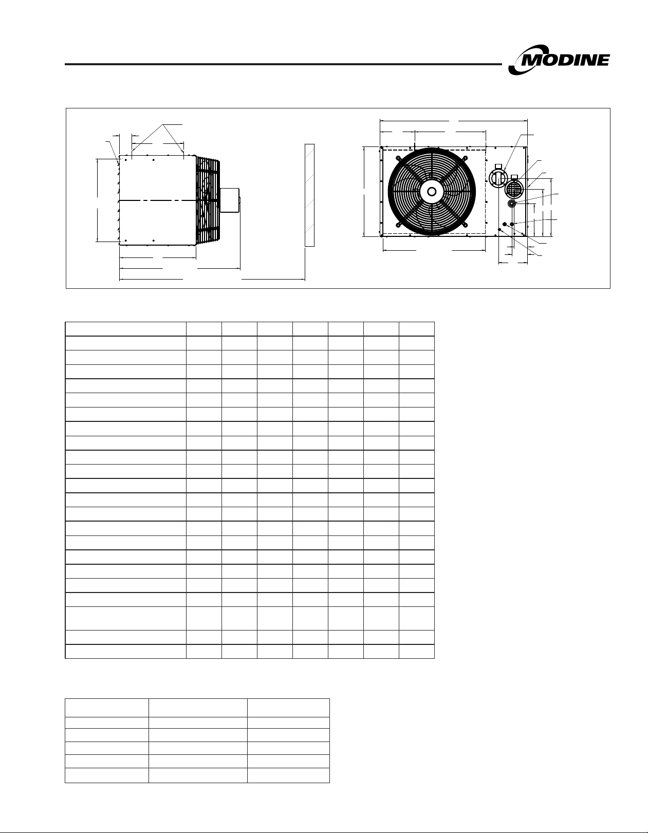
Figure 18.1 - Dimensional Drawings - Models HDS/HDC
13.5" BETWEEN 3/8"-16 MOUNTING HOLES
(MODEL SIZES 100 AND 125 ONLY)
10.0"
BLOWER
(MODEL HDC ONLY)
D OPENING
MOUNTING HOLES TYP
3/8" X 1" LONG
BLOWER
(MODEL HDC ONLY)
14.9" BETWEEN 3/8"-16 MOUNTING HOLES
(MODEL SIZES 100 AND 125 ONLY)
G
SIGHT GLASS
C
J (PROPELLER MODEL HDS)
J - (BLOWER MODEL HDC)
I
3.5"
ADJUSTABLE
LOUVERS
E
OPENING
1.0"
B
ACCESS VIEW
Table 18.1 - Dimensions (inches) j
Propeller Model Size - HDS Blower Model Size - HDC
Dimension 30 45 60 75 100/125 60 75 100/125
A 26.8 26.8 26.8 26.8 35.5 26.8 26.8 35.5
B 12.2 12.2 18 18 20.5 18 18 20.5
C 16.5 16.5 16.5 16.5 22 16.5 16.5 22
D 14.9 14.9 14.9 14.9 22.5 14.9 14.9 22.5
E 10.1 10.1 15.9 15.9 18.4 15.9 15.9 18.4
F 7.25 7.25 10.75 10.75 14 10.75 10.75 14
G 18.5 18.5 18.5 18.5 - 18.5 18.5 -
H 7.6 7.6 7.835 7.835 8.4 7.835 7.835 8.4
I 34.5 34.5 34.5 34.5 43 35.5 35.5 44.5
J 22 22 25 25 31 32.5 32.5 41.5
K 2.74 2.74 3.15 3.15 3.87 3.15 3.15 3.87
L 3.19 3.19 5.55 5.55 10.73 5.55 5.55 10.73
Gas Connecton 1/2" 1/2" 1/2" 1/2" 1/2" 1/2" 1/2" 1/2"
Vent and Combustion
Air Connector Size
Fan or Blower Diameter 10 10 14 14 18 9 - 7 9 - 7 10 - 10
Approx. Weight (lbs.) 55 60 80 85 125 92 97 125
3 3 4 4 4 4 4 4
A
REAR VIEW
K
ELECTRICAL
CONNECTION
H
MOUNTING
BRACKETS
POWER VENTER
VENT PIPE CONNECTION
GAS
CONNECTION
ACCESS
PANEL
F
L
COMBUSTION AIR
INTAKE PIPE
CONNECTION
j Do not use propeller units with duct work.
Figure 18.2 - Mounting Bracket Slot Locations
Mounting brackets are slotted to accomodate
joists on 16" or 24" centerlines.
HDS/HDC
.00
1.10
.00
1.50
5.50
3.50
3.10
7.50
5.10
9.50
7.10
18
30-75
9.10
HDS/HDC
100/125
(Accessory)
19.10
17.10
21.10
25.50
23.10
27.50
25.10
29.50
26.20
31.50
33.50
Table 18.2 - Clearances
35.00
6-175.9
DIMENSIONAL DATA - MODEL PTS
Figure 19.1 - Dimensional Drawings - Model PTS
G
ADJUSTABLE
LOUVERS
E
OPENING
4 MOUNTING
R
HOLES
S
B
C
M (APPROX)
Q (MIN DIST TO WALL)
T
Table 19.1 - Dimensions (inches) - PTS j
Models PTS150 PTS175 PTS200 PTS250 PTS300 PTS350 PTS400
A 35.53 42.53 42.53 42.53 42.53 42.53 42.53
B 23.06 25.81 25.81 31.31 31.31 39.56 39.56
C 22.05 22.05 22.05 22.05 22.05 22.05 22.05
D 22.52 29.52 29.52 29.52 29.52 29.52 29.52
E 21.18 23.93 23.93 29.43 29.43 32.17 32.17
F 15.33 16.70 16.70 19.45 19.45 23.58 23.58
G (Mounting Hole) k
H 8.37 8.37 8.37 8.37 8.37 8.37 8.37
I 4.50 4.50 4.50 4.50 4.50 4.50 4.50
J 8.09 9.47 9.47 6.72 6.72 10.84 10.84
K 3.87 3.87 3.87 5.20 5.20 5.20 5.20
L 12.17 13.55 13.55 12.66 12.66 16.78 16.78
M 31.79 32.83 34.43 33.83 33.83 34.83 34.83
Q l
R 3.56 3.56 3.56 3.56 3.56 3.56 3.56
S 14.90 14.90 14.90 14.90 14.90 14.90 14.90
T 10.00 10.00 10.00 10.00 10.00 10.00 10.00
U 13.54 20.53 20.53 20.53 20.53 20.53 20.53
Gas Connection 1/2 1/2 1/2 3/4 3/4 3/4 3/4
Vent and Combustion
Air Connector Size
Fan Diameter 20.00 22.00 22.00 22.00 22.00 24.00 26.00
Approx. Shipping Weight (lbs.) 165 210 220 265 270 310 320
3/8-16 3/8-16 3/8-16 3/8-16 3/8-16 3/8-16 3/8-16
43.79 44.83 46.43 45.83 45.83 46.83 46.83
4" 4"` 4" 6" 6" 6" 6"
A
U
J
D OPENING
K
I
H
j Do not use propeller units with duct work.
k Listed is the hole diameter and threads per
inch to accept threaded rod.
l Dimension equals overall plus 12".
POWER VENTER
VENT PIPE CONNECTION
COMBUSTION
AIR INLET
ACCESS PANEL
GAS
CONNECTION
F
L
T-STAT
CONNECTION
ELECTRICAL
CONNECTION
MOTOR CORD
STRAIN RELIEF
Table 19.2 - Clearances to Combustible Materials
Unit Side
Combustible Materials Service Clearance
Top and Bottom 6" 6"
Access Side 6" 18"
Non-Access Side 6" 6"
Rear 18" 18"
Vent Connector 6" 6"
Clearance To Recommended
6-175.9
19
DIMENSIONAL DATA - MODEL BTS
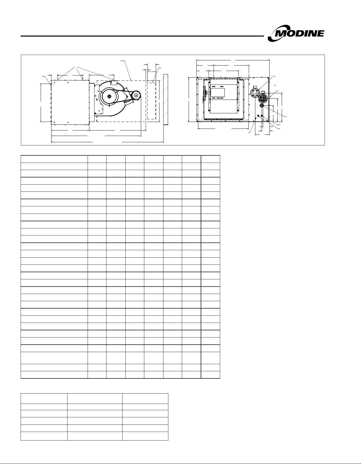
Figure 20.1 - Dimensional Drawings - Model BTS
BLOWER ENCLOSURE
(OPTIONAL)
V
M (APPROX.)
Q (MIN DIST TO WALL)
4 7/8"
4.88
O x P
FILTER RACK
(OPTIONAL)
7/8"
N
T
W
B
ADJUSTABLE
LOUVERS
OPENING
6 MOUNTING
HOLES
G
R
S
E
C
Table 20.1 - Dimensions (inches) — BTS
Models BTS150 BTS175 BTS200 BTS250 BTS300 BTS350 BTS400
A 35.53 42.53 42.53 42.53 42.53 42.53 42.53
B 23.06 25.81 25.81 31.31 31.31 39.56 39.56
C 22.05 22.05 22.05 22.05 22.05 22.05 22.05
D 22.52 29.52 29.52 29.52 29.52 29.52 29.52
E 21.18 23.93 23.93 29.43 29.43 32.17 32.17
F 15.33 16.70 16.70 19.45 19.45 23.58 23.58
G (Mounting Hole) j
H 8.37 8.37 8.37 8.37 8.37 8.37 8.37
I 4.50 4.50 4.50 4.50 4.50 4.50 4.50
J 8.09 9.47 9.47 6.72 6.72 10.84 10.84
K 3.87 3.87 3.87 5.20 5.20 5.20 5.20
L 12.17 13.55 13.55 12.66 12.66 16.78 16.78
M k
N 33.18 33.90 33.90 39.88 39.88 39.88 39.88
O 23.90 24.13 24.13 27.04 27.04 28.57 28.57
P 24.77 24.52 24.52 27.19 27.19 28.28 28.28
Q (w/Blower Encl & Filter Rack) 73.04 73.70 73.70 79.68 79.68 79.68 79.68
Q (w/o Blower Encl & Filter Rack) 64.25 64.19 64.19 70.88 70.88 70.88 70.88
R 3.56 3.56 3.56 3.56 3.56 3.56 3.56
S 14.90 14.90 14.90 14.90 14.90 14.90 14.90
T 10.00 10.00 10.00 10.00 10.00 10.00 10.00
U 13.54 20.53 20.53 20.53 20.53 20.53 20.53
V 14.52 14.52 14.52 18.04 18.04 18.00 18.00
W 3.27 7.15 7.15 4.77 4.77 5.24 5.24
X 17.38 17.38 17.38 20.38 20.38 20.38 20.38
Gas Connection 1/2 1/2 1/2 3/4 3/4 3/4 3/4
Vent and Combustion
Air Connector Size
Blower 12-12 12-12 12-12 15-15 15-15 15-15 15-15
Approx. Shipping Weight (lbs.) 220 275 280 340 345 395 405
3/8-16 3/8-16 3/8-16 3/8-16 3/8-16 3/8-16 3/8-16
52.25 52.19 52.19 58.88 58.88 58.88 58.88
4" 4" 4" 6" 6" 6" 6"
A
U
X
D OPENING
20.53
MOTOR CORD
STRAIN RELIEF
H
K
I
POWER VENTER
VENT PIPE
CONNECTION
ACCESS PANEL
F
L
J
T-STAT CONNECTION
ELECTRICAL
CONNECTION
GAS
CONNECTION
j Listed is the hole diameter and threads per inch to
accept threaded rod.
k This is an approximate dimension for standard
motors, allow 3" for sheave and optional motors.
Table 20.2 - Clearances to Combustible Materials
Unit Side
Combustible Materials Service Clearance
Top and Bottom 6" 6"
Access Side 6" 18"
Non-Access Side 6" 6"
Rear 18" 18"
Vent Connector 6" 6"
20
Clearance To Recommended
6-175.9

SPECIFICATIONS - ALL MODELS
General
A. Standards
All unit(s) shall include:
A.1. ETL design certification for use in both the US and
Canada to the ANSI Z83.8 - latest revision, standard for
“Gas Unit Heater and Gas-Fired Duct Furnaces” for safe
operation, construction, and performance.
B. Mechanical Configuration
B.2. Furnace(s) section with 82% minimum efficiency
provided by an indirect-fired tubular heat exchanger
with individually fired tubes.
C. Venting Arrangement
C.3. The unit shall be separated combustion. The venting
shall be a power exhausted arrangement with a
separate combustion air intake pipe connection to allow
for fresh combustion air from outside the conditioned
space. The unit shall be tested to insure proper ignition
when the unit is subjected to 40 mile per hour wind
velocities. The unit shall also include a factory mounted
differential pressure switch designed to prevent main
burner ignition until positive venting has been proven.
D. Unit Casing
D.1 The unit heater(s) casing shall be constructed of not
less than 20 gauge aluminized steel with minimization
of exposed fasteners. (PTS/BTS models)
D.1.a. The unit heater(s) casing shall be constructed of not
less than 22 gauge aluminized steel with minimization
of exposed fasteners. (HDS/HDC models)
D.2. All exterior casing parts casing parts shall be cleaned of
all oils and a phosphate coating applied prior to
painting. All exterior casing parts shall be painted with a
electrostatically applied baked-on gray-green polyester
powder paint (7-mil thickness) for corrosion resistance.
D.3. The unit shall be furnished with horizontal air deflectors.
The deflectors are adjustable to provide for horizontal
directional airflow control (up or down).
E. Furnace Section
E.1.c. The heat exchanger(s) shall be made of 18 gauge
aluminized steel tubes and headers (opt 409 stainless
steel). The thermal efficiency of the unit(s) shall be a
minimum of 82% efficient for all air flow ranges. Each
heat exchanger tube shall be individually and directly
flame-fired. The heat exchanger tube shall be crimped
to allow for thermal expansion and contraction. The flue
collector box shall be made of 20 gauge aluminized
steel (opt 409 stainless).
E.2. The heat exchanger(s) seams and duct connections
shall be certified to withstand 0.9" W.C. external static
pressure without burner flame disturbance.
E.3.a. The burner(s) shall be in-shot type, directly firing each
heat exchanger tube individually and is (are) designed
for good lighting characteristics without noise of
extinction for both natural and propane gas.
E.5. The ignition controller(s) shall be 100% shut-off with
continuous retry.
E.6. The gas pressure shall be between 6-7" W.C for natural
gas. (opt) The gas pressure shall be 11-14" W.C. for
propane gas.
6-175.9
E.7.a. The solid state ignition system shall directly light the gas
by means of a direct spark igniter each time the system
is energized.
E.8. The unit gas controls shall be provided with the
following:
E.8.d. (opt) Single-stage gas controls with a single-stage
combination gas control, an ignition control, and a
single-stage low voltage thermostat. The unit fires at
100% full fire based on a call for heat from a room
thermostat.
E.8.e. (opt) Two-stage gas controls with a two-stage
combination gas control, an ignition control, and a twostage low voltage thermostat. The unit fires at 50% fire
on low stage or 100% fire on high stage of the unit
based on the call for heat from either a room or duct
thermostat.
E.9. An automatic reset high limit switch mounted in the air
stream to shut off the gas supply in the event of
overheating.
E.10. A time delay relay that delays the start of the air mover
to allow the heat exchanger a warm-up period after a
call for heat. The time delay relay shall also continue the
air mover operation after the thermostat has been
satisfied to remove any residual heat in the heat
exchanger.
E.11. The unit shall be orificed for up to 2000' elevation above
sea level. (opt) The unit shall be orificed for _____
elevation above sea level.
F. Electrical
F.1. All electrical components shall carry UL, ETL, or CSA
listing.
F.2. A low voltage terminal board shall be provided for direct
wiring connection to an external thermostat.
F.3. A single 115V to 24V step down transformer shall be
provided for all unit controls.
G. Air Mover
G.1. The motor horsepower shall be ____.
G.2. The motor wiring shall be in flexible metal BX conduit.
G.3. (opt) The motor shall be controlled by a time delay relay.
G.4. Propeller models shall meet the following requirements.
G.4.a. The motor type shall be single-speed, totally enclosed (TE)
(open drip proof (ODP) on HDS units 75MBH and smaller).
G.4.b. The motor shall be rated for:
(a) 115V/60Hz/1Ph
G.5. Blower models shall meet the following requirements.
G.5.a. The motor type shall be single-speed, totally enclosed (TE)
(open drip proof (ODP) on all HDC models).
G.5.b. The motor shall be rated for:
(a) 115V/60Hz/1Ph
(b) 208V/60Hz/1Ph (BTS model)
(c) 230V/60Hz/1Ph (BTS model)
(d) 208V/60Hz/3Ph (BTS model)
(e) 230V/60Hz/3Ph (BTS model)
(f) 460V/60Hz/3Ph (BTS model)
(g) 575V/60Hz/3Ph (BTS model)
21

SPECIFICATIONS - ALL MODELS
G.5.c. The motor shall be provided with an adjustable motor
sheave to allow for minor adjustment of the blower rpm
at the job site. (BTS model)
G.5.d. The blower shall be a double width, double inlet (DWDI),
forward curved, belt driven, assembly with spider ball
bearings. (BTS model)
G.5.e. The motor shall be provided with three speed taps to
allow for adjustment of the blower rpm at the job site.
(HDC model)
G.5.f. The blower shall be a double width, double inlet (DWDI),
forward curved, direct motor drive assembly with spider
ball bearings. (HDC model)
H. Mounting
H.1. The unit shall be equipped with tapped holes to accept
3/8-16 threaded rod for suspension. (HDS/HDC size
100/125 and PTS/BTS models).
H.1.a. The unit shall be equipped with mounting brackets to
allow for threaded rod suspension or to be bolted
directly to the ceiling support structure allowing 1" of
top clearance. (HDS/HDC models - opt on sizes
100/125)
H.3. Propeller unit (Sizes 30-400) and blower units
(Sizes 60-125) to have 4 suspension points.
H.4. Blower unit (Sizes 150-400) to have 6 suspension
points.
J. Accessories
The following field installed accessory control devices shall be
provided with the unit:
J.1. A 5-50 psi gas pressure regulator to reduce the inlet gas
pressure for the operating controls.
J.2. A clear plastic thermostat guard with two keys for room
thermostats.
J.4. Pipe Hanger Adapter Kit to facilitate threaded pipe
suspension. (HDS/HDC size 100/125 and PTS/BTS
models)
J.7. Vertical Deflector Kit to enable side distribution of
airflow.
J.8. A blower enclosure fully encloses blower to enable the
attachment of filter racks and/or duct.
J.9. A combination filter rack/duct connector containing a 1"
thick, cleanable filter.
J.11. A belt guard enclosing the belts and sheaves (pulleys)
on a blower type unit heater. (BTS model)
J.12. Propane conversion kit for converting natural gas units
to propane gas.
J.17. Discharge Transition from unit to polytube. (HDC/BTS
models)
J.18. 30° non-velocity generating downward air deflector hood
constructed of 20 ga. cold rolled steel with baked-on
gray-green polyester powder paint.
J.19. 60° non-velocity generating downward air deflector hood
constructed of 20 ga. cold rolled steel with baked-on
gray-green polyester powder paint.
J.20. 90° non-velocity generating downward air deflector hood
constructed of 20 ga. cold rolled steel with baked-on
gray-green polyester powder paint.
J.21. (opt) A 208V to 115V step down shall be provided for
operation of the 115V unit (HDS/HDC/PTS models).
J.22. (opt) A 230V to 115V step down shall be provided for
operation of the 115V unit (HDS/HDC/PTS models).
J.23 (opt) A 460V to 115V step down shall be provided for
operation of the 115V unit (HDS/HDC/PTS models).
J.24. (opt) A 575V to 115V step down shall be provided for
operation of the 115V unit (HDS/HDC/PTS models).
J.25. A 208V to 115V step down shall be provided for
operation of the 115V power exhauster and control
circuit. (BTS model)
J.26. A 230V to 115V step down shall be provided for
operation of the 115V power exhauster and control
circuit. (BTS model)
J.27. A 460V to 115V step down shall be provided for
operation of the 115V power exhauster and control
circuit. (BTS model)
J.28. A 575V to 115V step down shall be provided for
operation of the 115V power exhauster and control
circuit. (BTS model)
J.29. A horizontal concentric vent kit shall be provided to allow
the vent outlet and combustion air inlet pipes to
penetrate the building wall through one opening.
J.30. A vertical concentric vent kit shall be provided to allow
the vent outlet and combustion air inlet pipes to
penetrate the building roof through one opening.
K. Thermostats
The unit shall be provided with the following thermostat:
K.2. A single stage room thermostat with a 50°-90°F range.
K.3. A field installed single stage room thermostat with a
50°-90°F temperature set point range. The stat shall
also include switching for Heat/Off and Fan On/Auto
control.
K.4. Honeywell TH5220D1029 digital non-programmable
room stat with switching - range 40-90°F.
K.5. A field installed two-stage duct thermostat with a
0°-100°F range and 20-foot capillary.
K.6. A two-stage electronic duct thermostat with field installed
temperature sensor, temperature selector and one stage
adder.
22
6-175.9
MODEL NOMENCLATURE
Figure 23.1 - Model Number Designations
PTS 200 A S 1101 S B A N
Separated Combustion Unit Configuration
HDS - Propeller Unit, 30-125MBH
HDC - Blower Unit, 60-125MBH
PTS - Propeller Unit, 150-400MBH
BTS - Blower Unit, 150-400MBH
MBH Input (refer to pages 6 & 7)
100 - 100,000 Btu/hr input
200 - 200,000 Btu/hr input
250 - 250,000 Btu/hr input
etc.
Heat Exchanger Type
A - Aluminized
S - Stainless Steel
Ignition Type
S - Direct Spark
Future
A = All
Dev Digit
Fanguard Digit
N = None (All blower models)
S = Standard
F = Fingerproof
Control Code Type (refer to page 12)
11 - Natural gas, single stage
12 - Natural gas, two-stage
21 - Propane, single stage
22 - Propane, two-stage
Power Code (refer to pages 8 & 9)
01 - 115V/60Hz/1ph
02 - 230V/60Hz/1ph
etc.
Factory Installed
Option Digit
N = None
6-175.9
23

The Modine brand has been the
industry standard since Arthur B.
Modine invented and patented
the first lightweight, suspended
hydronic unit heater in 1923.
No other manufacturer can
provide the combined application
flexibility, technical expertise and
fast delivery found at Modine.
Consult your local Modine
distributor for help in solving your
indoor air problems.
Products from Modine are designed to provide indoor air-comfort and ventilation
solutions for residential, commercial, institutional and industrial applications.
Whatever your heating, ventilating and air conditioning requirements, Modine
has the product to satisfy your needs, including:
HVAC
• Unit Heaters:
– Gas
– Hydronic
– Electric
– Oil
• Ceiling Cassettes
• Duct Furnaces
• Hydronic Cabinet Unit Heaters, Fin Tube, Convectors
• Infrared Heaters
• Make-up Air Systems
• Unit Ventilators
Ventilation
• Packaged Rooftop Ventilation
School Products
• Vertical Packaged Classroom HVAC:
– DX Cooling/Heat Pump
– Water/Ground Source Heat Pump
– Horizontal/Vertical Unit Ventilators
Geothermal
• Water-to-Water
• Water-to-Air
• Combination
Specific catalogs are available for each product. Catalogs 75-136 and 75-137
provide details on all Modine HVAC equipment.
Modine Manufacturing Company
1500 DeKoven Avenue
Racine, Wisconsin 53403-2552
Phone: 1.800.828.4328 (HEAT)
www.modinehvac.com
© Modine Manufacturing Company 2018
 Loading...