

Page 1
2-529.0
5H0916060000
October, 2023
INSTALLATION AND SERVICE MANUAL
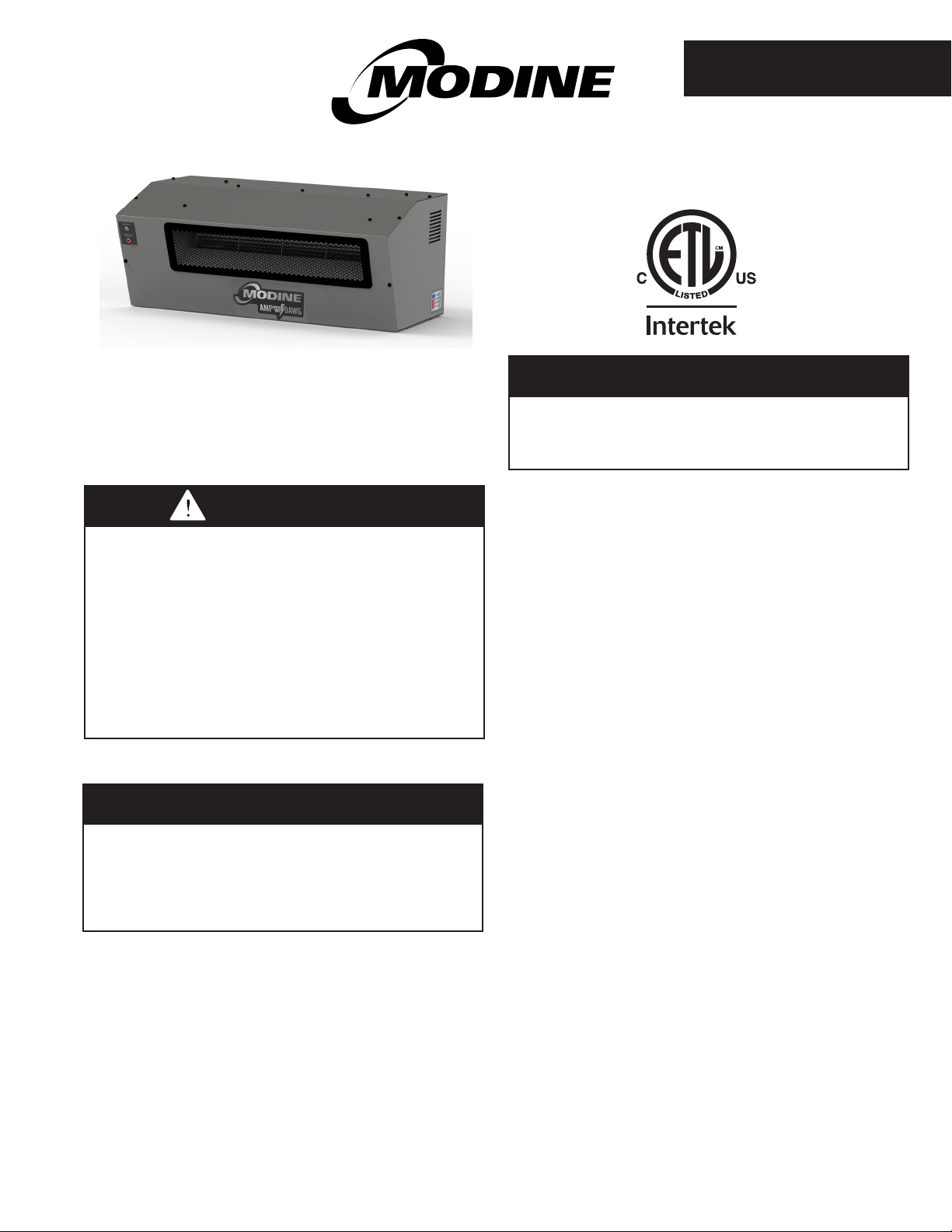
Residential Electric Unit Heater
Model AMP
FOR YOUR SAFETY
The use and storage of gasoline or other
flammable vapors and liquids in open containers in
the vicinity of this appliance is hazardous.
W ARNING
W ARNING
Improper installation, adjustment, alteration,
service, or maintenance can cause property
damage, injury, or death, and could cause
exposure to substances which have been
determined by various state agencies to cause
cancer, birth defects, or other reproductive
harm. Read the installation, operating, and
maintenance instructions thoroughly before
installing or servicing this equipment.
IMPOR T ANT
The use of this manual is specifically intended for
a qualified installation and service agency. All
installation and service of these units must be
performed by a qualified installation and service
agency.
Inspection on Arrival
1. Inspect unit upon arrival. In case of damage, report it
immediately to transportation company and your local
Modine sales representative.
2. Check rating plate on unit to verify that power supply and
motor specification requirements meets available electric
power at the point of installation.
3. Inspect unit upon arrival for conformance with description of
product ordered (including specifications where applicable).
General Information
Installation and wiring of these electric unit heaters must
conform to all applicable local codes and the National Electric
Code. Wiring of these electric unit heaters should only be
performed by a qualified electrician.
Table of Contents
General Information ................................................................... 1
Special Precautions / Important Information.............................. 2
Unit Location ............................................................................. 3
Unit Mounting .........................................................................3-4
Installation ................................................................................. 4
Electrical Connections .......................................................... 5
Operation ................................................................................... 6
Operating Sequence ............................................................. 6
Dimensional Data ..................................................................... .7
Performance Data ..................................................................... 7
Motor Specifications .................................................................. 7
General Maintenance & Troubleshooting. ................................. 8
Warranty ................................................................Back 2 Pages
THIS MANUAL IS THE PROPERTY OF THE OWNER.
PLEASE BE SURE TO LEAVE IT WITH THE OWNER WHEN YOU LEAVE THE JOB.
Page 2
SPECIAL PRECAUTIONS / IMPORTANT INSTRUCTIONS
SPECIAL PRECAUTIONS / IMPORTANT
INSTRUCTIONS
THE INSTALLATION AND MAINTENANCE INSTRUCTIONS
IN THIS MANUAL MUST BE FOLLOWED TO PROVIDE SAFE,
EFFICIENT AND TROUBLE-FREE OPERATION. IN ADDITION,
PARTICULAR CARE MUST BE EXERCISED REGARDING
THE SPECIAL PRECAUTIONS LISTED BELOW. FAILURE
TO PROPERLY ADDRESS THESE CRITICAL AREAS COULD
RESULT IN PROPERTY DAMAGE OR LOSS, PERSONAL
INJURY, OR DEATH. THESE INSTRUCTIONS ARE SUBJECT
TO ANY MORE RESTRICTIVE LOCAL OR NATIONAL CODES.
HAZARD INTENSITY LEVELS
1. DANGER: Indicates an imminently hazardous situation
which, if not avoided, WILL result in death or serious injury.
2. WARNING: Indicates a potentially hazardous situation which,
if not avoided, COULD result in death or serious injury.
3. CAUTION: Indicates a potentially hazardous situation which,
if not avoided, MAY result in minor or moderate injury.
4. IMPORTANT: Indicates a situation which, if not avoided,
MAY result in a potential safety concern.
DANGER
Appliances must not be installed where they may be exposed
to a potentially explosive or flammable atmosphere.
WARNING
1. Disconnect power supply before making wiring connections
to prevent electrical shock and equipment damage.
2. All appliances must be wired strictly in accordance with
wiring diagram furnished with the appliance. Any wiring
different from the wiring diagram could result in a hazard
to persons and property.
3. Ensure that the supply voltage to the appliance, as
indicated on the serial plate, is not 5% greater than rated
voltage.
4. When servicing or repairing this equipment, use only
factory-approved service replacement parts. A complete
replacement parts list may be obtained by contacting
Modine Manufacturing Company. Refer to the rating
plate on the appliance for complete appliance model
number, serial number, and company address. Any
substitution of parts or controls not approved by the
factory will be at the owner's risk.
5. Do not operate any heater if it malfunctions. Disconnect
power at service panel and have heater inspected by a
qualified installation and service agency.
6. Do not insert or allow foreign objects to enter any intake
or exhaust opening.
7. Use this heater only as described in this manual.
8. Components of the heater are hot when in use. To avoid
burn, do not let bare skin touch hot surfaces.
9. Extreme caution is necessary when any heater is used
by or near chidren or invalids and whenever the heater is
left operating and unattended.
10.The heater must be installed properly before use.
1. All literature shipped with this unit should be kept for
future use for servicing or service diagnostics. Do not
discard any literature shipped with this unit.
2. Be sure no obstructions block air intake or discharge of
the appliance.
3. Do not install applicane in outdoor, wet or moist
locations.
4. Do not install appliance outdoors.
5. Clearances to combustible materials are critical. Be
sure to follow all listed requirements. See Table 3.1.
6. The bottom of the appliance must be at least - 6ft from
the finished floor in the USA and 8ft in Canada.
7. Do not attach duct work, air filters, or polytubes to any
appliance.
8. Ensure that the supply voltage to the appliance, as
indicated on the serial plate, is not 5% less than the rated
voltage.
9. Do not reuse any electrical component which has been
wet. Such component must be replaced.
10. When servicing or repairing this equipment, use only
factory approved service replacement parts. A complete
replacement parts list may be obtained by contacting
Modine Manufacturing Company. Parts not approved by
the factory will be at the owner’s risk.
11. Do not operate any heater if it malfunctions. Disconnect
power at service panel and have heater inspected by a
qualied installation and service agency.
12. Do not reuse any electrical component which has been
wet. Such component must be replaced.
13.
SAVE THESE INSTRUCTIONS.
1. To check most of the Possible Remedies in the trouble shooting guide listed in Table 8.1, refer to the applicable
sections of the manual.
2. Start-up and adjustment procedures must be performed by
a qualified service agent.
CAUTION
IMPORTANT
2
2-529.0
Page 3
INSTALLATION
DANGER
Appliances must not be installed where they may be exposed
to a potentially explosive or flammable atmosphere.
CAUTION
1. Be sure no obstructions block air intake or discharge of
the appliance.
2. Do not install appliance in outdoor, wet, or moist
locations.
In locating units, consider general space-heating requirements
of the area. Unit heaters should be located so they discharge
air nearly parallel to exposed walls. Arrange units so they do
not blow directly at occupants. Interference of air streams by
columns, beams, partitions, or other obstructions should be
avoided as much as possible.
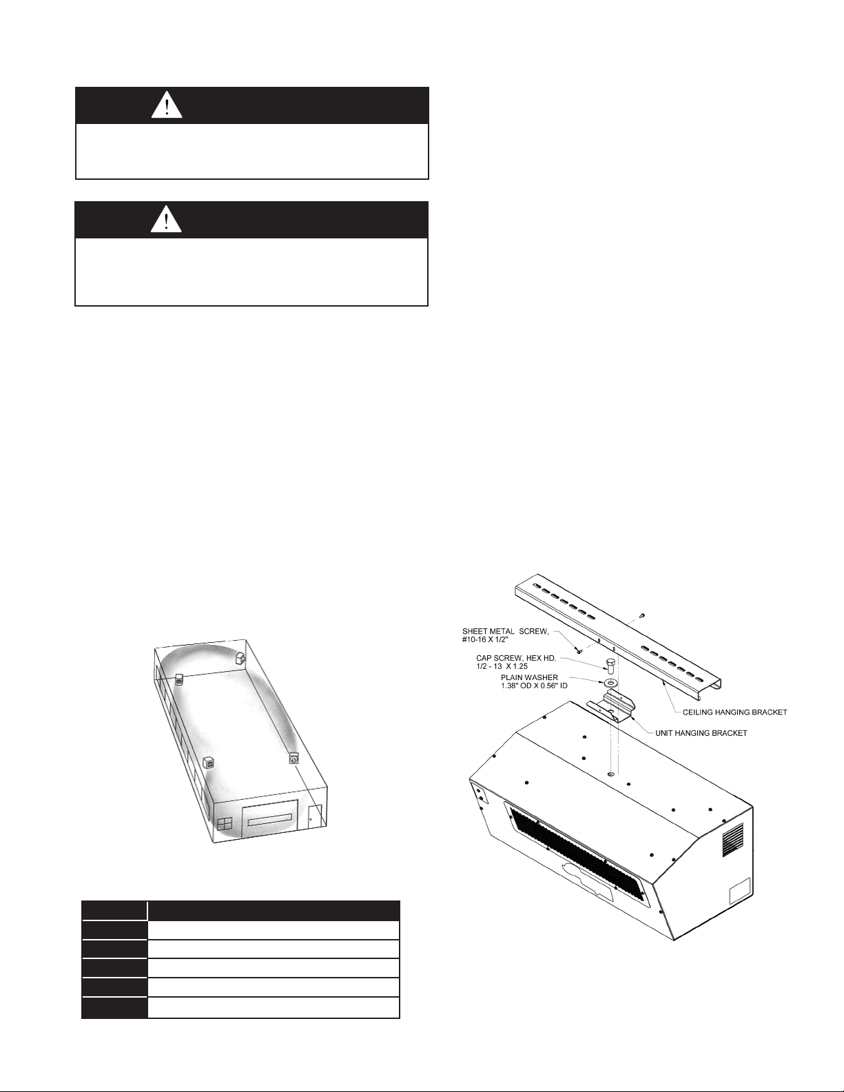
In multiple unit installations, arrange units so that each supports
the air stream of the next unit, thus creating circulatory air
movement in the area. See Figure 3.1. A large portion of the
heated air should be directed toward the side of the building
exposed to prevailing winds.
Height at which unit heaters are installed is critical. Maximum
mounting heights for all units are listed in Table 7.1. The
maximum mounting height for any unit is that height above
which the unit will not deliver heated air to the floor. The
maximum mounting heights must not be exceeded in order
to assure maximum comfort. It is critical that the unit has
adequate clearance from combustible materials as listed in
Table 3.1.
UNIT MOUNTING
For best performance do not install the unit heater above the
maximum suggested mounting height shown in Table 7.1. Do
not install the unit below 6ft in the USA, or 8ft in Canada shown
in Table 7.1. The bottom of the unit must be unobstructed, and
may not be used on a shelf or platform. The unit is provided
with a mounting rail, hanging bracket, and hardware to install in
a ceiling-mounted application, shown in Figure 3.2. Be sure the
means of suspension is adequate to support the weight of the
unit (see table 7.1 for unit weights). For proper operation, the unit
must be installed in a level horizontal position.
Standard ceiling mounting (Figure 3.2):
Secure the mounting rail to the ceiling joists or truss, using
¼” lag screws with minimum ½”OD washers furnished by the
installer. Insure clearance for unit installation and removal.
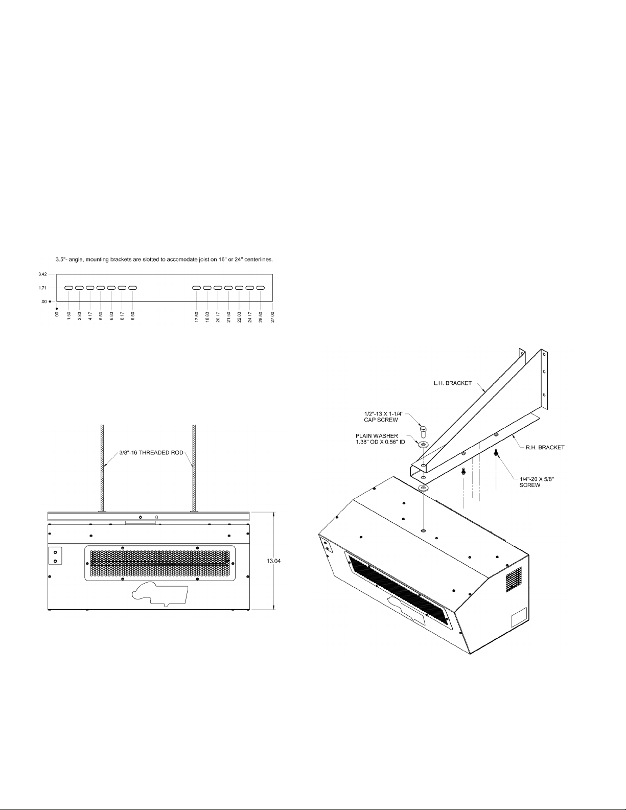
The mounting rail is slotted to accommodate joists on 16” or 24”
centerlines, and can be installed across joists or on the same joist
depending on desired unit position and access.
One tapped hole (1/2”-13) is provided in the top of the casing for
unit heater suspension. A hanging bracket is supplied with the
unit, and should be installed with the provided 1/2" -13 x 1-1/4"
cap screw and washer. This bolt should be secured to the unit
to a minimum of 24 ft-lbs of torque . This bracket can be installed
at an angle if required for insertion to the mounting rail. Once
installed, slide the hanging bracket into the mounting rail, and
secure from the front with the provided #10-16 screw to prevent
movement of the heater in the rail, see Figure 3.2.
Figure 3.2 - Standard Ceiling Mount
Figure 3.1 - Typical Unit Locations
Table 3.1 - Clearance to Combustibles
Unit Side Clearance to Combustible Material
Top 1"
Sides 1"
Bottom 12" min for adequate air flow
Rear 12" min / 18" preferred for servicability
Front Avoid obstructions as much as possible.
2-529.0
3
3
Page 4
INSTALLATION
Ceiling suspension by threaded rod (Figure
4.2):
The unit can also be hung with threaded rod utilizing the
same mounting brackets. Refer to Figure 4.1. Two 3/8” rods
should be secured to an appropriate field-provided structural
member such as a steel angle or channel. The rods should
be spaced a minimum of 16” apart, equally located from
the center line of the bracket. The threaded rods should be
secured with washers and lock nuts, lock washers and nuts,
or a washer with a double nut arrangement (all field-provided).
The mounting rail should be level after securing the rods. The
hanging bracket can then be installed on the unit and slid
and secured into the rail as defined in the standard ceiling
mounting section.
Figure 4.1 - Mounting Bracket Detail
Wall-Mounting Bracket (Figure 4.3)
For installations where ceiling suspension is not feasible, a wallmounting bracket kit is available as a factory provided accessory
kit. The bracket has a built-in wall clearance, and provides a
convenient wall mounting method. The one-point suspension
permits swiveling the unit prior to securing to orient the heater in
the most effective air direction.
1. Assemble L.H. side bracket to R H. side bracket and
fasten with 1/4"-20 x 5/8" screws (provided) to weldnuts
inside R.H. bracket.
2. Secure the mounting bracket to the wall using ¼” lag
screws with minimum ½”OD washers furnished by the
installer.
3. Raise the unit into position and fasten to the wall
bracket with one 1/2" -13 x 1-1/4" cap screw and
washer (provided). Swivel unit to desired position
before tightening capscrew.
Figure 4.3 Wall-Mounting Bracket
Figure 4.2 - Threaded Rod Mount
44
2-529.0
Page 5
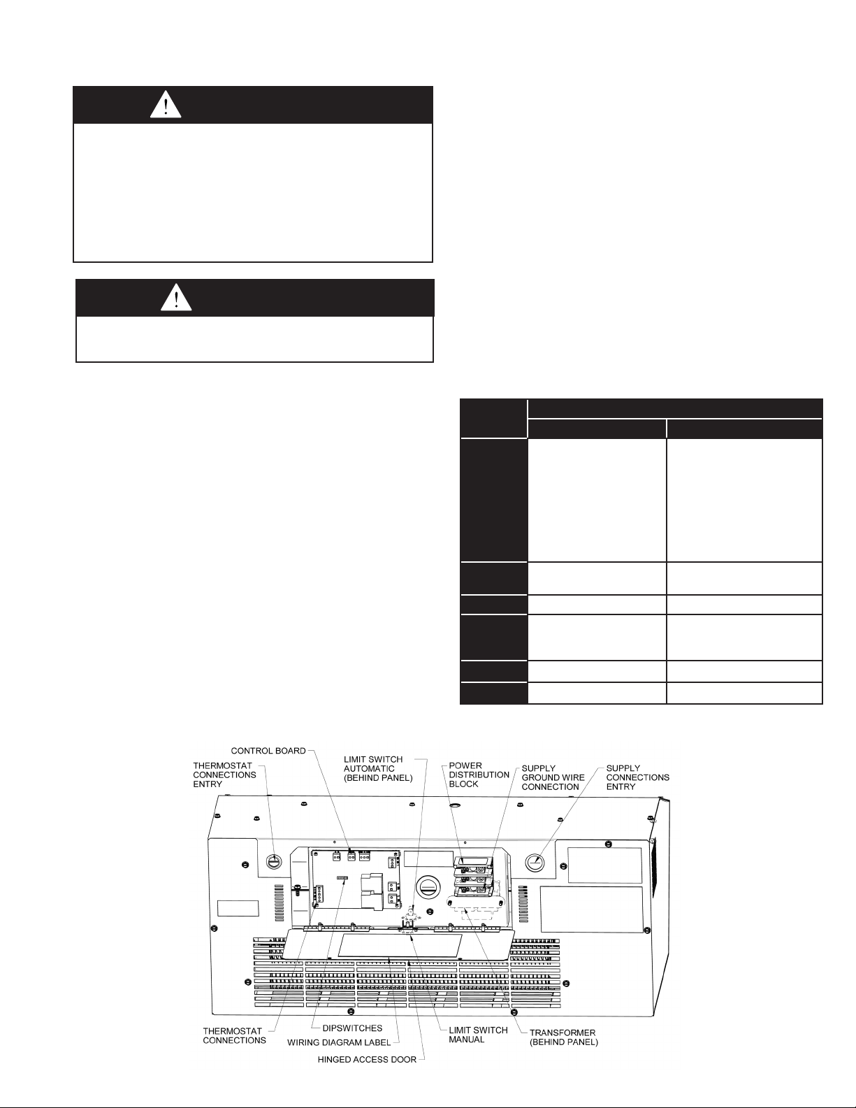
INSTALLATION
Electrical Connections
W ARNING
1. Disconnect power supply before making wiring connections to
prevent electrical shock and equipment damage.
2. All appliances must be wired strictly in accordance with wiring
diagram furnished with the appliance. Any wiring different
from the wiring diagram could result in a hazard to persons
and property.
3. Ensure that the supply voltage to the appliance, as indicated on the
serial plate, is not 5% greater than rated voltage.
CAUTION
Ensure that the supply voltage to the appliance, as indicated
on the serial plate, is not 5% greater than rated voltage
1. Installation of wiring must conform with local building
codes, or in the absence of local codes, with the National
Electric Code ANSI/NFPA 70 - Latest Edition. Unit must
be electrically grounded in conformance to this code.
In Canada, wiring must comply with CSA C22.1, Part 1,
Electrical Code.
2. Two copies of the unit wiring diagram are provided with each
unit. One is located inside the control panel access door and
the other is supplied in the literature packet. Refer to this
diagram for all wiring connections.
3. The power supply to the unit must be protected with a fused
or circuit breaker switch.
4. The power supply must be within 5% of the voltage rating
and each phase must be balanced within 2% of each other. If
not, advise the utility company.
5. External electrical service connections that must be installed include:
a. Supply power connection (208-240 volts). Remove the
two screws holding the control panel access cover. The
heater is provided with a 7/8" hole on the right side of the
access panel for use with 1/2" conduit, or a 1-1/8"
knockout for 3/4" conduit. Appropriate conduit and fittings
Figure 5.1 - Control Board
must be provided for safe installation. Allow for
approximately 6" of wire inside the unit for connections.
Connect the power supply wire to the terminals of the
power distribution block marked L1 and L2. Torque
terminal screw to 40 in-lbs. Connect the power supply
ground wire to the termination. Torque screw to 40
in-lbs.
b. Connection of thermostats, or any other accessory
control devices that may be supplied (24 volts). A split
grommet is located on the left side of the back panel
to pass the thermostat cable through. Wire thermostat
leads to the appropriate corresponding thermostat
terminal blocks on the left side of control board. If the
thermostat is single-stage (W only), or the unit is a
AMP057 model, wire the W signal to the W1 terminal of
the control board.
6. On the control board, there is a bank of dipswitches that
allow for modified operation based on application. Set
control board dipswitches to desired function if different
than standard. See Figure 5.1 and Table 5.1.
Table 5.1 - Dipswitch settings
Dipswtich
Number
1
2
3 Unused Unused
j
4
5 Unused Unused
6 Unused Unused
j Enabling high fan speed at low stage will allow the unit to have the Airflow, Air Throw,
and Max Mounting Height shown for the AMP090 in table 7.1. Air temp rise for the AM057
performance table 7.1 will be reduced by 10°F.
Off (default) On
AMP057 UNUSED
AMP090 - Enables unit
for 2-stage thermostat.
On a fan-only (G) call,
unit will run at low speed.
On a low-stage heat (W/
W1) call, unit will run at
low fan speed.
Dipswitch Position
AMP057 UNUSED
AMP090 - Enables unit for
single stage thermostat. Unit
will start in low stage and call
for high stage if after running
for 10 minutes it doesn't
meet call for heat.
On a fan-only (G) call, unit
will run at high speed.
On a low-stage heat (W/W1)
call, unit will run at high fan
speed.
2-529.0
5
Page 6
OPERATION
WARNING
The heater must be properly installed before use.
IMPOR T ANT
Start-up and adjustment procedures must be performed by a
qualified service agency.
Prior to Operation
Although this unit has been inspected and tested at the factory,
the following procedures should be performed to assure proper
on-site operation:
1. Check all electrical connections to be sure they are secure,
and in accordance with the wiring diagram.
2. Check firmness of unit suspension. Tighten all fasteners, if
necessary.
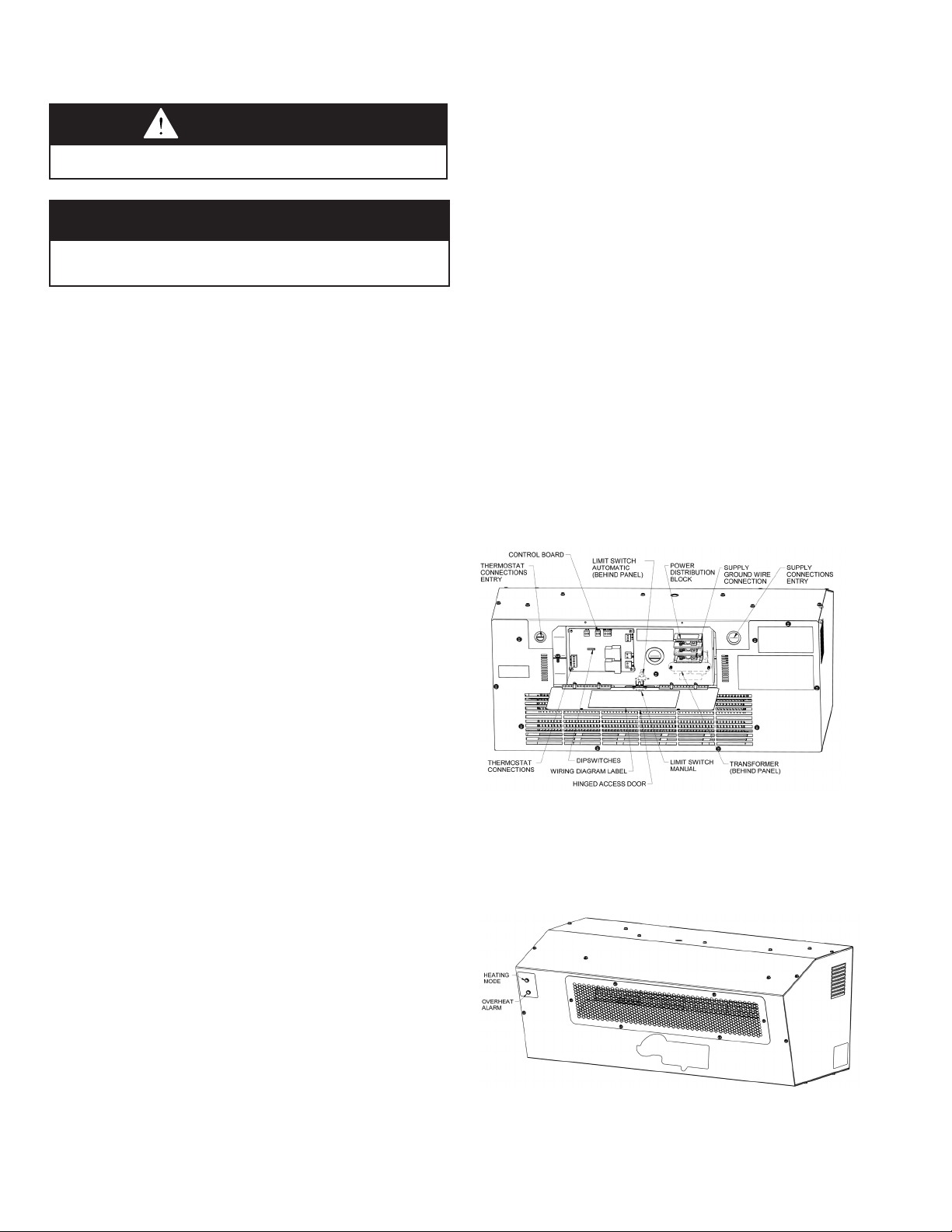
Safety Devices
The overheat controls, mounted on the bottom of the control
section (See Figure 6.1), will interrupt power to the unit
contactor in the event of overheating. The limit nearest the fan
scroll is a single-pole, single-throw switch, with an automatic
reset. The limit nearest the control panel opening is a singlepole, single-throw switch, with a manual reset. If either of
these limits is tripped, the red overheat alarm indicator on the
front of the unit will illuminate (See Figure 6.2). During this
state, power to the elements will be disrupted, but the controls
will permit the motor to continue operation and cool the
heater. The overheat controls should operate only when
something is wrong with the unit or space temperature.
When this control operates, correct the difficulty
immediately or serious and permanent damage may
result. If the Overheat Alarm indicator light is illuminated, it is
recommended that the unit be disconnected from power at the
breaker until the unit can be inspected and the issue resolved.
Do not continue to use heater if it repeatedly overheats to cycle
the safety thermal limit.
The motor for the blower wheel has internal thermal overload
protection. If for any reason the motor overheats, the thermal
protector will shut it off. The motor will restart automatically
when it has cooled. In the event of a complete motor failure,
the manual limit will trip and prevent the elements from heating/
cycling. Following motor servicing/replacement, the manual
reset button must be pressed to reset the switch prior to the
elements functioning again.
Initial Start-Up
1. Set thermostat above room temperature.
2. Turn on power to the unit.
3. Run the unit through several cycles by raising and lowering
the thermostat setting to assure proper sequence of
operation.
Operating Sequence
The operation of this electric unit heater is governed by
a microprocessor control board which is controlled by a
thermostat. The board completes the electric circuit to the
heating elements when the thermostat “calls” for heat. The
green ‘Heating Mode’ indictor light on the front of the unit will
illuminate when this occurs. The fan motor is also activated
shortly after the thermostat “calls” for heat. When the thermostat
is satisfied, the control board opens the circuit to the heating
elements. There is a cooldown period where the fan will
continue to operate after the elements are de-energized to
dissipate the remaining heat from the elements before fully
shutting off.
Figure 6.1 - Control Board
Figure 6.2 - Indicator Lights
66
2-529.0
Page 7
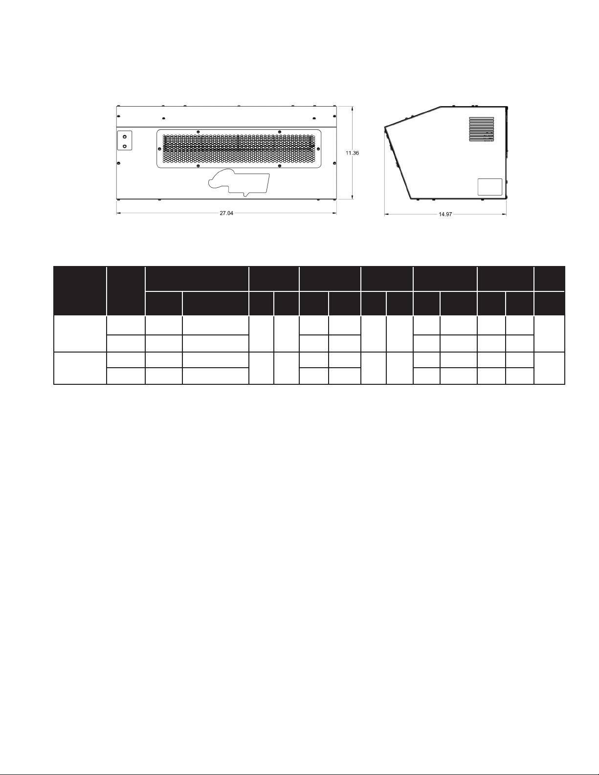
DIMENSIONAL / PERFORMANCE DATA
Figure 7.1 - Unit Dimensions (inches)
Table 7.1 - Performance Data / Mounting Height
Heating Capacity Airflow Temp Rise Heat Throw
Model Size Voltage
kw BTU/HR CFM m3hr °F °C ft m ft m ft m lbs
240V 5.7 19,437
AMP057
j Capacity, airflow, temperature rise and throw values also correspond to low stage of AMP090
j
208V 4.3 14,578 31.8 17.6 6/8 1.8/2.4 8 2.4
240V 9.0 30,690
AMP090
208V 6.8 23,018 38.8 21.5 6/8 1.8/2.4 10 3
425 722
550 934
42.3 23.5
20 6.1
51.7 28.7
26 7.9
Min. Height
(USA/Canada)
6/8 1.8/2.4 8 2.4
6/8 1.8/2.4 10 3
Suggested
Max. Height
Weight
48
52
2-529.0
7
Page 8
GENERAL MAINTENANCE / TROUBLESHOOTING
Routine Unit Maintenance
CAUTION
WARNING
1. When servicing or repairing this equipment, use only
factory approved service replacement parts. A complete
replacement parts list may be obtained by contacting
Modine Manufacturing Company. Parts not approved by the
factory will be at the owner’s risk.
2. Do not operate any heater if it malfunctions. Disconnect
power at service panel and have heater inspected by a
qualified installation and service agency.
3. Do not reuse any electrical component which has been wet.
Such component must be replaced.
Replacement parts can be obtained from Modine by submitting
the model number, power code, control code and serial number
shown on the rating plate attached to the unit, along with a
description of the part.
Under average conditions, it is recommended that unit heaters
be serviced at least once a year and checked out prior to the
heating season. In excessively dirty atmospheres, service
should be performed more often.
1. Disconnect power supply to the unit before performing any
of the following maintenance or inspection procedures & allow
heating elements of heater to cool.
2. Check all components and wiring inside the unit for firm
connections and/or wear.
NOTE: To check most of the Possible Remedies in the
trouble-shooting guide listed in Table 8.1, refer to the
applicable sections of the manual.
3. Verify unit mounting is secure, and tighten any hardware that
seems loose.
4. Fan motor is permanently lubricated for normal operation.
Under severe conditions, lubricate with non-detergent
SAE 20 motor oil.
5. Routine cleaning of the unit casing and outlet screen is
recommended to remove dirt, grease, or corrosive substances
that may damage the finish. Rusted or corroded spots on the
outlet screen or casing should be sanded and repainted.
6. Check entire electrical system before every heating season.
Table 8.1 - Troubleshooting
PROBLEM POSSIBLE CAUSE(S) REMEDY
Unit does not operate 1. Electric circuit in open position.
2. Tripped breaker or fuse of circuit.
3. Defective or incorrect wiring.
4. Defective thermostat or switch.
5. Defective or burned out control transformer
6. Defective control board
1. Power interrupted by overheat control.
Fan operates but
element does not heat
Elements heat but fan
does not operate
2. Unit receiving fan only call.
3. Defective or incorrect wiring.
1. Blown motor fuse
2. Fan motor failure
3. Summer-winter switch defective or
improperly wired.
4. Defective or incorrect wiring.
1. a. Turn on switch or thermostat
b. Move thermostat to higher setting.
c. Replace fuse or reset disconnect
2. Replace fuses or reset breaker
3. Check wiring and connections. Refer to diagram inside
control panel.
4. Check continuity with volt-ohmmeter. Replace defective part
if necessary.
5. Check secondary voltage with voltmeter. Replace if
necessary.
6. Replace if necessary
1. Defective limit control. Check wiring and connections. Check
continuity through control. Replace if necessary.
2. Check thermostat settings, wiring and connections.
3. Check all wiring and connections. See diagram inside access
panel.
1. Check fuse on control board, replace if necessary
2. a. Check for loose electrical connetions. Check wiring with
diagram in control compartment.
b. Repair or replace defective motor.
c. Voltage too high or too low. Check voltage with voltmeter.
3. Check for continuity with volt-ohmmeter. Replace if
necessary.
4. Check all wiring and connections. See diagram inside contol
compartment.
Insufficient heat
8
1. Too few units or under sized unit(s) for heat
loss.
2. Unit(s) mounted too high.
3. Airflow too low.
4. Burned out element.
2-529.0
1. Add more units or increase size of unit(s)
2. Lower unit(s)
3. Check motor rpm against namplate rating. Replace motor if
speed is too slow
4. Disconnect internal wiring and check individual element
resistance with ohmmeter (50.5 ohms +/- 5%).
Page 9

Page Left Intentionally Blank
2-529.0
9
Page 10

Page Left Intentionally Blank
10
2-529.0
Page 11

WARRANTY
This Warranty (the “Warranty”) shall apply to Products
(as defined below) sold by Modine Manufacturing Company,
a Wisconsin corporation (“Seller”) to you (“Buyer”).
Seller hereby warrants that during the Applicable Warranty
Period (as defined below) its Products shall be free from
defects in material and factory workmanship under normal
use and service, subject to the EXCLUSIONS described
below and according to the terms outlined in this Warranty.
If Seller receives written notice of a breach of this Warranty
prior to the end of the Applicable Warranty Period (which
such notice shall include the model and serial numbers of
the Product, as well as the date and a reasonably detailed
description of the Product’s alleged failure), Buyer shall with
Seller’s prior written approval, return the applicable Product
or component thereof to Seller with shipping charges prepaid;
if upon examination by Seller such Product or component
thereof is disclosed to have been defective, then Seller will,
without charge to Buyer, at Seller’s option, either repair the
Product, replace defective parts in the Product, or offer an
entire replacement unit of the Product; provided that the
warranty period for a Product that has been repaired or
provided with replacement parts shall not extend beyond
the original Applicable Warranty Period, nor shall any
replacement parts provided for a Product be under any
warranty beyond the original Applicable Warranty Period for
the Product; similarly, if Seller provides an entire replacement
unit of the Product, the warranty period for the replacement
unit is limited to the remainder of the original Applicable
Warranty Period. Seller shall have no responsibility for
installation, service, field labor, shipping, handling, or other
costs or charges, except as expressly provided in this
Warranty. Buyer shall have no remedy hereunder for any
defective part returned without proper written authorization
from Seller, as described above.
For purposes of this Warranty and subject to the exclusions
described below, the term “Products” shall mean parts or
equipment manufactured by Seller, sold to Buyer pursuant
to a purchase contract between Buyer and Seller (most
often initiated by a purchase order issued by Buyer and
accepted by Seller), and expressly described in such
contract. The term “Products” shall not include third-party
parts or equipment furnished by Seller, except that, to the
extent assignable, Seller will assign to Buyer the benefits
(together with all limitations and exclusions) of the thirdparty manufacturer’s warranty for such parts or equipment.
This Warranty extends only to the original purchase contract
between Buyer and Seller and is nontransferable, except that
this Warranty may be assigned to an Authorized End User (as
defined below). All replaced parts or equipment shall become
Seller’s property. For purposes of this Warranty, the term
“Applicable Warranty Period” shall mean the warranty period
set forth in the table below for each type or class of Product
described on the table; provided that, when the Product is
to be used as a component part of equipment manufactured
by Buyer, the Applicable Warranty Period shall be limited
to one (1) year after the date of shipment from Seller,
notwithstanding anything in the table below to the contrary.
For purposes of this Warranty, the term “Authorized End
User” shall mean any third-party that purchases the Product
directly or indirectly from Buyer for the Authorized End User’s
own use upon the first installation of the Product and not for
resale.
BUYER HEREBY ACKNOWLEDGES THAT ITS REMEDIES
FOR BREACH OF THIS WARRANTY, EXCLUSIVE OF ALL
OTHER REMEDIES PROVIDED BY LAW, ARE LIMITED AS
DESCRIBED ABOVE.
EXCLUSIONS AND LIMITATIONS: This Warranty is subject to
the following exclusions and limitations:
The term “Products” shall not include and this Warranty shall not
apply to any of the following items: refrigerant gas, belts, filters,
fuses and other items consumed or worn out by normal wear and
tear.
In addition, this Warranty shall not apply to:
(1) Products or components thereof that are damaged or
adversely affected by conditions beyond Seller’s control,
including but not limited to polluted or contaminated or foreign
matter contained in the air or water utilized for heat exchanger
(condenser) cooling or if the failure of the part is caused by
improper air or water supply, or improper or incorrect sizing of
power supply;
(2) Any Products or components thereof which have been
repaired or altered outside the factory of Seller in any way, or
otherwise subject to unauthorized repairs or alterations, so as,
in the judgment of Seller, to affect the Product’s durability or
performance;
(3) Materials or labor of any kind not furnished by Seller, or
any charges for any such labor or materials, whether such labor,
materials or charges thereon are due to replacement of parts,
adjustments, repairs, or any other work done by any party other
than Seller;
(4) Labor or other costs incurred for diagnosing, repairing,
removing, installing, shipping, servicing, or handling of either
defective or replacement parts;
(5) Any Products removed from their original location for
reinstallation in another location;
(6) Any Products or components thereof which have been
operated, maintained, or serviced contrary to Seller’s written
installation, operation, and/or servicing instructions or owner’s
manual;
(7) Damages resulting from operation with an inadequate or
interrupted supply of air or water;
(8) Any Products or components thereof which have been
subjected to misuse, negligence, faulty installation, improper
servicing, accident, excessive thermal shock, excessive humidity,
physical damage, impact, abrasion, improper operation, or other
operating conditions in excess of or contrary to those for which
such equipment was designed;
(9) With respect to gas-fired or oil-fired units, any Products or
components thereof if the input to the Product exceeds the rated
input (as indicated on the Product’s serial plate) by more than five
percent (5%);
(10) Any Products or components thereof which, in the judgment
of Seller, have been installed in a corrosive atmosphere, marine,
or coastal application, subjected to corrosive fluids or gases, or
damaged or adversely affected by the effects of the physical or
chemical properties of water or steam or other liquids or gases
used in the Products or any component thereof;
(11) Damage or failure to start resulting from improper voltage
conditions, blown fuses, open circuit breakers, or other
2-529.0
11
Page 12
inadequacy or interruption of electrical service or fuel supply; or
(12) Any Products or components thereof from which the serial
number has been altered, defaced or removed.
BUYER AGREES THAT THE WARRANTIES AND REMEDIES
DESCRIBED HEREIN ARE THE ONLY WARRANTIES AND
REMEDIES PROVIDED BY SELLER WITH RESPECT TO THE
PRODUCTS AND TO THE MAXIMUM EXTENT PERMITTED
UNDER APPLICABLE LAW SHALL BE IN LIEU OF AND
EXCLUSIVE OF ALL OTHER WARRANTIES AND REMEDIES
WHATSOEVER, EITHER EXPRESS OR IMPLIED, WHETHER
ARISING FROM LAW, COURSE OF DEALING, USAGE OF
TRADE, OR OTHERWISE, INCLUDING BUT NOT LIMITED
TO WARRANTIES OF MERCHANTABILITY, FITNESS FOR A
PARTICULAR PURPOSE, AND NON-INFRINGEMENT, EACH OF
WHICH SELLER HEREBY EXPRESSLY DISCLAIMS. SELLER
NEITHER ASSUMES (NOR HAS AUTHORIZED ANY PERSON
TO ASSUME) ANY OTHER WARRANTY OR LIABILITY IN
CONNECTION WITH ANY PRODUCTS. REPRESENATATIONS
AND CONDITIONS, EXPRESS OR IMPLIED BY STATUTE,
TRADE USAGE, OR OTHERWISE, ARE EXCLUDED AND WILL
NOT APPLY TO THE PRODUCTS UNDER THIS WARRANTY,
EXCEPT FOR WARRANTIES WHICH BY LAW CANNOT BE
EXCLUDED
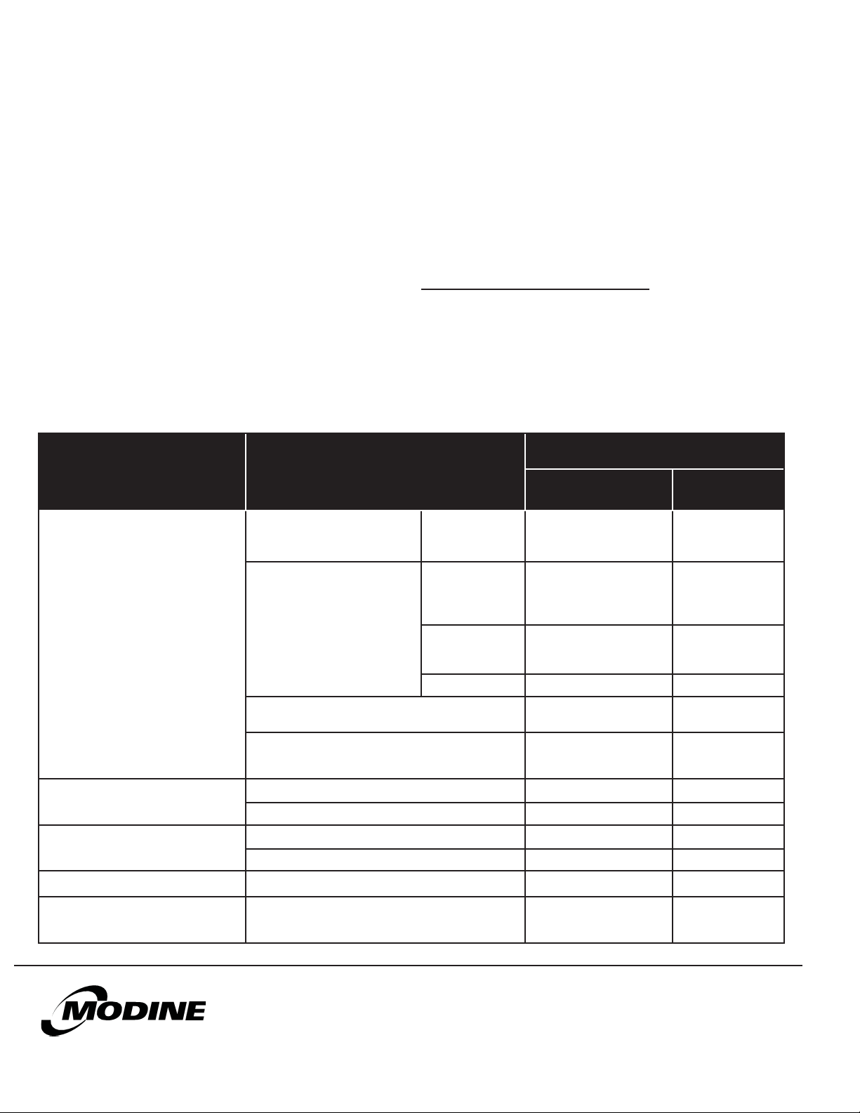
COMPONENT APPLICABLE MODELS
Gas Fired Unit Heaters with
Tubular Style Heat Exchangers
(e.g. HD, HDS, PTX, BTX, etc)
Gas Fired Unit Heaters
with Clam-Shell Style Heat
Heat Exchangers and/or Coils
Exchangers
(e.g. PDP, BDP, etc.)
OR LIMITED. Without limiting the
foregoing, Seller makes no and specifically disclaims all
representations and/or warranties that the Products will detect the
presence of, or eliminate, prevent, treat, or mitigate the spread,
transmission, or outbreak of any pathogen, disease, virus, or other
contagion, including but not limited to COVID 19.
BUYER AGREES THAT IN NO EVENT WILL SELLER BE
LIABLE FOR COSTS OF PROCESSING, LOST REVENUES OR
PROFITS, INJURY TO GOODWILL, OR ANY OTHER SPECIAL,
CONSEQUENTIAL, OR INCIDENTAL DAMAGES OF ANY KIND
RESULTING FROM THE PURCHASE OF THE PRODUCTS, OR
FROM BUYER’S USE OF ANY PRODUCT, WHETHER ARISING
FROM BREACH OF WARRANTY, NONCONFORMITY TO
ORDERED SPECIFICATIONS, DELAY IN DELIVERY, OR ANY
OTHER LOSS SUSTAINED BY THE BUYER.
OPTIONAL SUPPLEMENTAL WARRANTY
Buyer may purchase from Seller a supplemental warranty with
respect to Products which shall extend the Applicable Warranty
Period as set forth in the express terms and conditions described
in the supplemental warranty agreement. Such supplemental
warranty terms may include an additional four (4) years on certain
compressors, an additional five (5) years “all parts” warranty, an
additional four (4) or nine (9) years on certain heat exchangers, and/
or such additional supplemental warranty terms as Seller chooses to
make available to its customers from time to time.
APPLICABLE WARRANTY PERIOD
(WHICHEVER OCCURS FIRST)
Time from Date of First
Beneficial Use by Buyer or
Authorized End User
Aluminized or
Stainless Steel
Aluminized Steel
(not in highhumidity
applications)
Aluminized Steel
(in high-humidity
applications)
Stainless Steel 10 YEARS 126 MONTHS
10 YEARS 126 MONTHS
10 YEARS
(must be Stainless Steel in
high-humidity applications)
1 YEAR 18 MONTHS
Time from Date of
Shipment from Seller
126 MONTHS
Low Intensity Infrared Units 5 YEARS 66 MONTHS
Indoor and Outdoor Duct Furnaces and System Units,
Steam/Hot Water Units, Oil-Fired Units, Electric Units,
Cassettes, Vertical Unit Ventilators, Geothermal Units
Burners and Elements
High Intensity Infrared and Electric Infrared Units 1 YEAR 18 MONTHS
Compressors
Sheet Metal Parts All Products 1 YEAR 18 MONTHS
Components, excluding Heat
Exchangers, Coils, Condensers,
Burners, Sheet Metal
As Modine Manufacturing Company has a continuous product improvement program, it reserves the right to change design and specifications without notice.
© Modine Manufacturing Company 2023
12
Low Intensity Infrared Units 2 YEARS 30 MONTHS
Condensing Units for Cassettes 5 YEARS 66 MONTHS
Vertical Unit Ventilators, Geothermal Units 1 YEAR 18 MONTHS
All Products 2 YEARS 30 MONTHS
2-529.0
1 YEAR 18 MONTHS
Modine Manufacturing Company
1500 DeKoven Avenue
Racine, WI 53403
Phone: 1.800.828.4328 (HEAT)
www.modinehvac.com
 Loading...