

Page 1
WARNING
6-583.9
5H8000400000
July, 2016
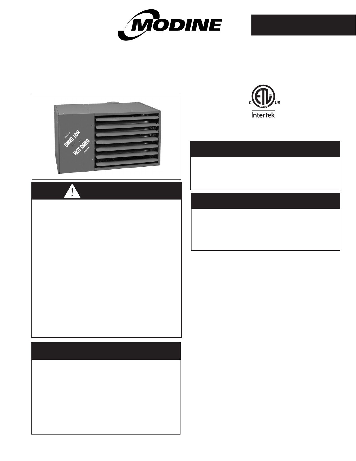
INSTALLATION AND SERVICE MANUAL
gas-fired unit heaters
model HD and HDB
All models approved for use in California by the CEC and
in Massachusetts. Unit heater is certified for residential and
commercial applications.
FOR YOUR SAFETY
The use and storage of gasoline or other
flammable vapors and liquids in open
containers in the vicinity of this appliance
is hazardous.
1. Improper installation, adjustment,
alteration, service, or maintenance can
cause property damage, injury, or death,
and could cause exposure to substances
which have been determined by various
state agencies to cause cancer, birth
defects, or other reproductive harm. Read
the installation, operating, and maintenance
instructions thoroughly before installing or
servicing this equipment.
2. Do not locate ANY gas-fired units in areas
where chlorinated, halogenated, or acid
vapors are present in the atmosphere.
These substances can cause premature
heat exchanger failure due to corrosion,
which can cause property damage, serious
injury, or death.
FOR YOUR SAFETY
WHAT TO DO IF YOU SMELL GAS:
1. Open windows.
2. Do not try to light any appliance.
3. Do not touch any electrical switch; do
not use any phone in your building.
4. Immediately call your gas supplier
from a neighbor’s phone. Follow the gas
supplier’s instructions. If you can not reach
your gas supplier, call your fire department.
THIS MANUAL IS THE PROPERTY OF THE OWNER.
PLEASE BE SURE TO LEAVE IT WITH THE OWNER WHEN YOU LEAVE THE JOB.
IMPORTANT
The use of this manual is specifically
intended for a qualified installation and
service agency. All installation and service
of these units must be performed by a
qualified installation and service agency.
Inspection on Arrival
1. Inspect unit upon arrival. In case of damage, report it
immediately to the transportation company and your local
Modine sales representative.
2.
Check rating plate on unit to verify that power supply meets
available electric power at the point of installation.
3. Inspect unit upon arrival for conformance with description of
product ordered (including specifications where applicable).
Table of Contents
Inspection on Arrival ................................. 1
Special Precautions ................................. 2
SI (Metric) Conversion Factors......................... 3
Before You Begin ................................... 3
Unit Location....................................... 4
Combustible Material and Service Clearances ......... 4
Unit Mounting .................................. 5
Unit Installation ................................. 5
Venting ....................................... 6
Gas Connections............................... 12
High-Altitude Accessory Kit ....................... 13
Electrical ..................................... 15
Wiring/Blower Speed Adjustment .................. 16
Operation ........................................ 17
Unit Components .................................. 18
Dimensions....................................... 19
Service/Troubleshooting............................. 20
Unit Wiring Diagram ................................ 21
Model/Serial Number/Replacement Parts ............... 22
Commercial Warranty........................Back Cover
Page 2
SPECIAL PRECAUTIONS
SPECIAL PRECAUTIONS
THE INSTALLATION AND MAINTENANCE INSTRUCTIONS IN THIS
MANUAL MUST BE FOLLOWED TO PROVIDE SAFE, EFFICIENT, AND
TROUBLE-FREE OPERATION. IN ADDITION, PARTICULAR CARE
MUST BE EXERCISED REGARDING THE SPECIAL PRECAUTIONS
LISTED BELOW. FAILURE TO PROPERLY ADDRESS THESE
CRITICAL AREAS COULD RESULT IN PROPERTY DAMAGE OR
LOSS, PERSONAL INJURY, OR DEATH. THESE INSTRUCTIONS
SUBJECT TO ANY MORE RESTRICTIVE LOCAL OR NATIONAL
CODES.
HAZARD INTENSITY LEVELS
1. DANGER: Indicates an imminently hazardous situation
which, if not avoided, WILL result in death or serious injury.
2. WARNING: Indicates a potentially hazardous situation
which, if not avoided, COULD result in death or serious injury.
3. CAUTION: Indicates a potentially hazardous situation which,
if not avoided, MAY result in minor or moderate injury.
4. IMPORTANT: Indicates a situation which, if not avoided,
MAY result in a potential safety concern.
DANGER
Appliances must not be installed where they may be exposed
to a potentially explosive or flammable atmosphere.
WARNING
1. Gas fired heating equipment must be vented - do not
operate unvented.
2. A built-in power exhauster is provided - additional external
power exhausters are not required or permitted.
3. If an existing heater is being replaced, it may be necessary
to resize the venting systems. Improperly sized venting
systems can result in vent gas leakage or the formation of
condensate. Refer to the National Fuel Gas Code ANSI
Z223.1 (NFPA 54) or CSA-B149.1 - latest edition. Failure to
follow these instructions can result in injury or death.
4. Under no circumstances should two sections of double wall
vent pipe be joined together within one horizontal vent system
due to the inability to verify complete seal of inner pipes.
5. All field gas piping must be pressure/leak tested prior to
operation. Never use an open flame. Use a soap solution
or equivalent for testing.
6. Gas pressure to appliance controls must never exceed
14" W.C. (1/2 psi).
7. To reduce the opportunity for condensation, the minimum
sea level input to the appliance, as indicated on the serial
plate, must not be less than 5% below the rated input,
or 5% below the minimum rated input of dual rated units.
8. Disconnect power supply before making wiring connections
to prevent electrical shock and equipment damage.
9. All appliances must be wired strictly in accordance with
wiring diagram furnished with the appliance. Any wiring
different from the wiring diagram could result in a hazard to
persons and property.
10. Any original factory wiring that requires replacement must
be replaced with wiring material having a temperature
rating of at least 105°C.
11. Ensure that the supply voltage to the appliance, as indicated
on the serial plate, is not 5% greater than the rated voltage.
12. When servicing or repairing this equipment, use only
factory-approved service replacement parts. A complete
replacements parts list may be obtained by contacting
the factory. Refer to the rating plate on the appliance for
complete appliance model number, serial number, and
company address. Any substitution of parts or controls not
approved by the factory will be at the owner's risk.
2
6-583.9
CAUTION
1. All literature shipped with this unit should be kept for
future use for servicing or service diagnostics. Do not
discard any literature shipped with this unit.
2. Consult piping, electrical, and venting instructions in this
manual before final installation.
3. Do not attach ductwork, air filters, or polytubes to any
propeller unit heater.
4. Clearances to combustible materials are critical. Be sure to
follow all listed requirements.
5. Do not locate units in tightly sealed rooms or small
compartments (commonly referred to as confined spaces)
without provisions for adequate combustion air and venting.
Combustion air must have access to the confined space
through a minimum of two permanent openings in the
enclosure, at least one near the bottom. They should
provide a free area of one square inch per 1,000 BTU/Hr
input rating of the unit with a minimum of 100 square inches
for each opening, whichever is greater.
6. Low profile heaters are designed for use in heating
applications with ambient startup temperatures between
-40°F and 90°F, and ambient operating temperatures
between 40°F and 90°F.
7. Do not install unit outdoors.
8. In garages or other sections of aircraft hangars, such
as offices and shops that communicate with areas used for
servicing or storage, keep the bottom of the unit at least
7' above the floor unless the unit is properly guarded
to provide user protection from moving parts. In parking
garages, the unit must be installed in accordance with
the standard for parking structures ANSI/NFPA 88A latest
edition, and in repair garages the standard for repair garages
NFPA 30A - latest edition (Formerly NFPA 88B). In Canada,
installation of heaters in airplane hangars must be in
accordance with the requirements of the enforcing authority,
and in public garages in accordance with the current
CSA-B149 codes.
9. In aircraft hangars, keep the bottom of the unit at least 10'
from the highest surface of the wings or engine enclosure
of the highest aircraft housed in the hangars and in
accordance with the requirements of the enforcing authority
and/or NFPA 409 - latest edition.
10. Installation of units in high humidity or salt water
atmospheres will cause accelerated corrosion, resulting in
a reduction of the normal life of the units.
11. Do not install units below 7' measured from the bottom of
the unit to the floor in commercial applications (unless
unit is properly guarded to provide user protection from
moving parts) and 5' measured from the bottom of the unit
to the floor in residential applications.
12. Be sure no obstructions block air intake and discharge of
unit heaters.
13. The minimum distance from combustible material is based
on the combustible material surface not exceeding 160°F.
Clearance from the top of the unit may be required to be
greater than the minimum specified if heat damage, other
than fire, may occur to materials above the unit heater at
the temperature described.
14. Allow 18" of clearance at rear (or 6" beyond end of motor at
rear of unit, whichever is greater) and access side to provide
ample air for combustion and proper operation of fan.
15. Installation must conform with local building codes or in the
absence of local codes, with the National Fuel Gas Code,
ANSI Z223.1 (NFPA 54) - latest edition. In Canada,
installation must be in accordance with CSA-B149.1.
16. Purging of air from gas supply line should be performed as
described in the National Fuel Gas Code, ANSI Z223.1
(NFPA 54) - latest edition. In Canada, installation must be in
accordance with CSA-B149.1.
Page 3
SPECIAL PRECAUTIONS / SI (METRIC) CONVERSION FACTORS
BEFORE YOU BEGIN
CAUTION
17. When leak testing the gas supply piping system, the
appliance and its combination gas control must be isolated
during any pressure testing in excess of 14" W.C. (1/2 psi).
18. The unit should be isolated from the gas supply piping
system by closing its field installed manual shut-off valve.
This manual shut-off valve should be located within 6' of
the heater.
19. Turn off all gas before installing appliance.
20. Ensure that the supply voltage to the appliance, as
indicated on the serial plate, is less than 5% below the
rated voltage.
21. Check the gas inlet pressure at the unit upstream of the
combination gas control. The inlet pressure should be
6-7" W.C. on natural gas or 12-14" W.C. on propane. If
inlet pressure is too high, install an additional pressure
regulator upstream of the combination gas control.
22. Service or repair of this equipment must be performed
by a qualified service agency.
23. Do not attempt to reuse any mechanical or electronic
ignition controllers which has been wet. Replace defective
controller.
IMPORTANT
1. To prevent premature heat exchanger failure, do not locate
ANY gas-fired appliances in areas where corrosive vapors
(i.e. chlorinated, halogenated, or acidic) are present in the
atmosphere.
2. To prevent premature heat exchanger failure, the input to
the appliance as indicated on the serial plate must not
exceed the rated input by more than 5%.
3. To check most of the Possible Remedies in the trouble-
shooting guide listed in Table 19.1, refer to the applicable
sections of the manual.
CAUTION
1. All literature shipped with this unit should be kept for future
use for servicing or service diagnostics. Leave manual with
the owner. Do not discard any literature shipped with this unit.
2. Consult piping, electrical, and venting instructions in this
manual before final installation.
3. Do not attach ductwork, air filters, or polytubes to any
propeller unit heater.
In the U.S., the installation of these units must comply with the
National Fuel Gas Code, ANSI Z223.1 - latest edition (also
known as NFPA 54) and other applicable local building codes.
In Canada, the installation of these units must comply with local
plumbing or waste water codes and other applicable codes and
with the current code CSA-B149.1.
1. All installation and service of these units must be performed
by a qualified installation and service agency only as defined
in ANSI Z223.1 (NFPA 54) - latest edition, or in Canada by a
licensed gas fitter.
2. This unit is certified with the controls furnished. For
replacements parts, please order according to the
replacement parts list on serial plate. Always know your
model and serial numbers. Modine reserves the right to
substitute other authorized controls as replacements.
3. Unit is balanced for correct performance. Do not alter fan or
operate motors at reduced speed.
4. Information on controls is supplied separately.
5. The same burner is used for natural and propane gas.
SI (METRIC) CONVERSION FACTORS
To Convert Multiply By To Obtain
"W.C. 0.249 kPa
°F (°F-32) x 5/9 °C
Btu 1.06 kJ
Btu/ft3 37.3 kJ/m
Btu/hr 0.000293 kW
CFH (ft3/hr) 0.000472 m3/min
CFH (ft3/hr) 0.00000787 m3/s
CFM (ft3/min) 0.0283 m3/min
CFM (ft3/min) 0.000472 m3/s
To Convert Multiply By To Obtain
feet 0.305 m
Gal/Hr. 0.00379 m3/hr
Gal/Hr. 3.79 l/hr
3
gallons 3.79 l
Horsepower 746 W
inches 25.4 mm
pound 0.454 kg
psig 6.89 kPa
psig 27.7 "W.C.
6-583.9
3
Page 4
UNIT LOCATION
UNIT LOCATION
DANGER
Appliances must not be installed where they may be exposed
to a potentially explosive or flammable atmosphere.
CAUTION
1. Clearances to combustible materials are critical. Be sure to
follow all listed requirements.
2. Do not locate units in tightly sealed rooms or small
compartments (commonly referred to as confined spaces)
without provisions for adequate combustion air and
venting. Combustion air must have access to the confined
space through a minimum of two permanent openings in
the enclosure, at least one near the bottom. They should
provide a free area of one square inch per 1,000 BTU/Hr
input rating of the unit with a minimum of 100 square
inches for each opening, whichever is greater.
3. Low profile heaters are designed for use in heating
applications with ambient startup temperatures between
-40°F and 90°F, and ambient operating temperatures
between 40°F and 90°F.
4. Do not install unit outdoors.
5. In garages or other sections of aircraft hangars such
as offices and shops that communicate with areas used for
servicing or storage, keep the bottom of the unit at least
7' above the floor unless the unit is properly guarded. In
parking garages, the unit must be installed in accordance
with the standard for parking structures ANSI/NFPA
88A-latest edition, and in repair garages the standard for
repair garages NFPA 30A - latest edition (Formerly NFPA
88B). In Canada, installation of heaters in airplane hangars
must be in accordance with the requirements of the
enforcing authority, and in public garages in accordance
with the current CSA-B149 codes.
6. In aircraft hangars, keep the bottom of the unit at least 10'
from the highest surface of the wings or engine enclosure
of the highest aircraft housed in the hangars and in
accordance with the requirements of the enforcing authority
and/or NFPA 409 - latest edition.
7. Installation of units in high humidity or salt water atmospheres
will cause accelerated corrosion, resulting in a reduction of
the normal life of the units.
IMPORTANT
To prevent premature heat exchanger failure, do not locate
ANY gas-fired appliances in areas where corrosive vapors
(i.e. chlorinated, halogenated or acid) are present in the
atmosphere.
Location Recommendations
1. When locating the heater, consider general space and
heating requirements, availability of gas and electrical
supply, and proximity to vent locations.
2. When locating units, it is important to consider that the exhaust
vent piping must be connected to the outside atmosphere.
3. Be sure the structural support at the unit location site is
adequate to support the unit's weight. For proper operation
the unit must be installed in a level horizontal position.
4. Do not install units in locations where the flue products
can be drawn into the adjacent building openings such as
windows, fresh air intakes, etc.
Table 4.1 Clearances
Unit Side Clearance To Recommended
Combustible Materials Service Clearance
Top and Bottom 1" 1"
Access Side 18" 18"
Non-Access Side 1" 1"
Rear 18" 18"
Vent Connector 4" 4"
5. Be sure that the minimum clearances to combustible
materials and recommended service clearances are
maintained. Units are designed for installation with the
minimum clearances as shown in Table 4.1.
6. Do not install units in locations where the gas ignition system
is exposed to water spray, rain, or dripping water.
7. Mounting height (measured from bottom of unit) at which
unit heaters are installed is critical. Refer to mounting
height and heat throw data on page 17 of this manual. The
maximum mounting height for any unit is that height above
which the unit will not deliver heated air to the floor.
Combustion Air Requirements
The National Fuel Gas Code defines an “unconfined space”
as a space whose volume is greater than 50 cubic feet per
1,000 Btu/Hr input of the installed appliance(s). A confined
space is 50 cubic feet or less per 1,000 Btu/Hr input of the
installed appliance(s).
It is not recommended to install these unit heaters into
residential confined spaces. This recommendation is due to the
concern that at some point in time, the combustion air openings
provided by the installer may become blocked or eliminated by
the owner, either intentionally or unintentionally. Despite this
recommendation, if these units are installed into a residential
confined space, see National Fuel Gas Code ANSI Z223.1
(NFPA 54) or CSA-B149.1 Installation Code - latest edition, for
detailed combustion air provisions. The installation must adhere
to these requirements.
Units installed in confined spaces in industrial/commercial
installations must be provided with two permanent openings
- one near the top and one near the bottom of the confined
space. Each opening should have a free area of not less than
one square inch per 1,000 Btu/Hr of the total input rating of all
units in the confined space, freely communicating with interior
areas that have adequate infiltration from the outside.
For further details on supplying combustion air to a confined
(tightly sealed) space or unconfined space, see the National Fuel
Gas Code ANSI Z223.1 (NFPA 54) or CSA-B149.1 Installation
Code - latest edition.
Turning The Unit 180° (Model Sizes 30-75 Only)
All units are produced at the factory with left-side controls (when
looking at the unit). If the installation requires the controls to be
on the right side, all heaters - with the exception of the HD/HDB
100 and 125 - can be turned over by following the instructions
below.
• Byturningtheunit180°fromthewayitwasreceivedfrom
the factory, the sides become opposite, but the front and
back remain in the same relative position. The bottom
panel now becomes the top panel and vice-versa.
• Removetheaccesspanel,turnit180°,andre-attachitto
the unit so that all the information labels can be read.
• Removethespringloadeddeflectorblades,turnthemover,
replace, and adjust so they are open and in a position to
direct the heated air down to the floor.
4
6-583.9
Page 5
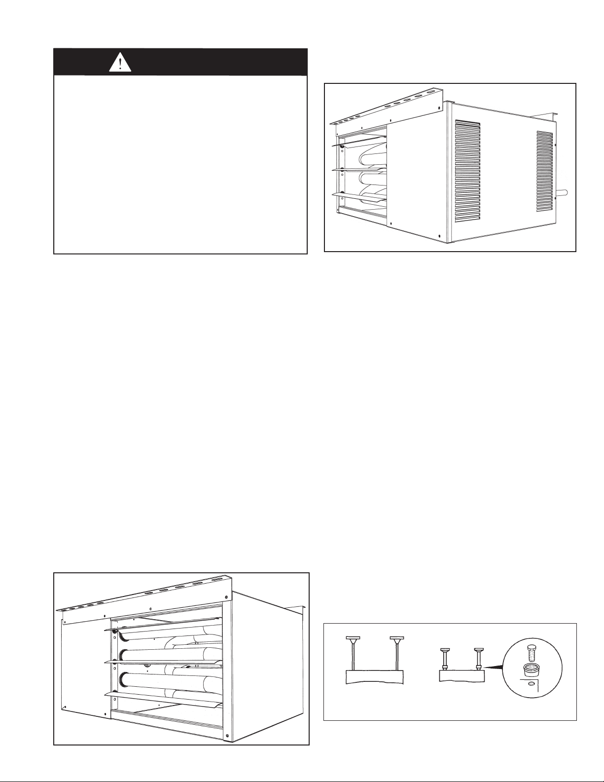
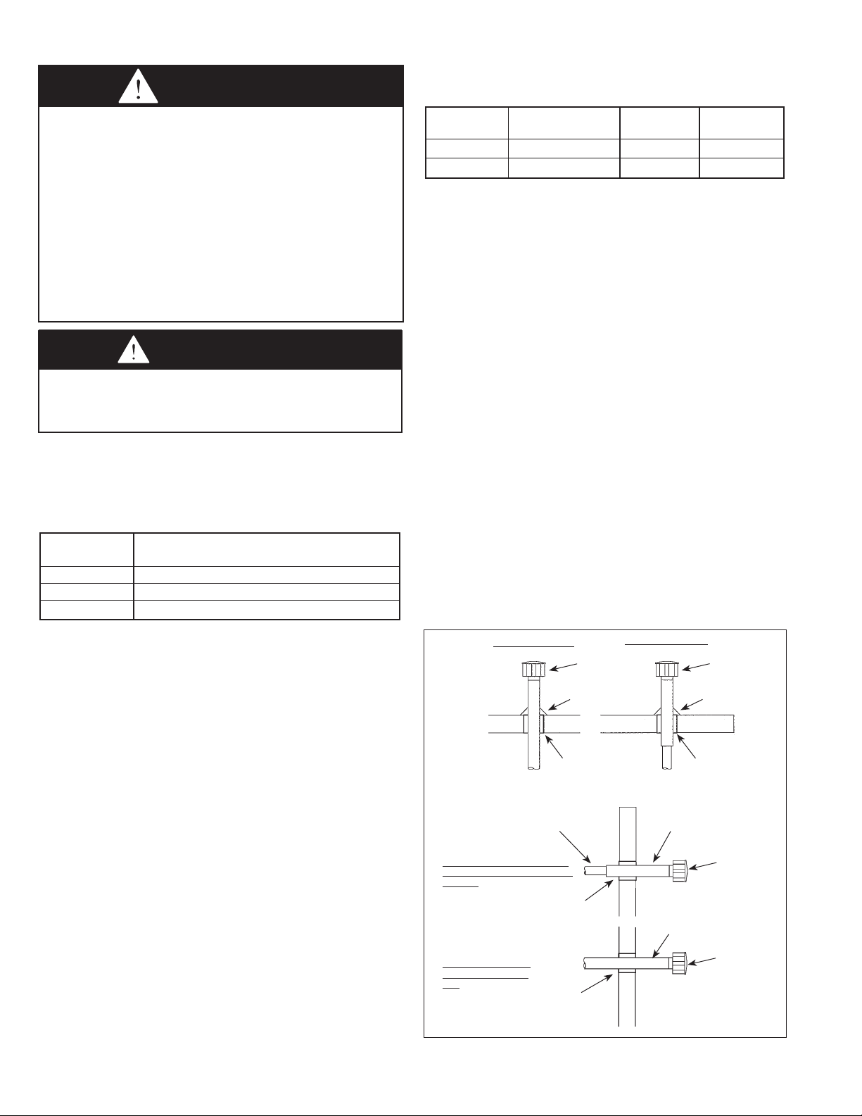
UNIT MOUNTING
CAUTION
1. Do not install units below 7' measured from the bottom of
the unit to the floor in commercial applications (unless
unit is properly guarded to provide user protection from
moving parts) and 5' measured from the bottom of the unit
to the floor in residential applications.
2. Be sure no obstructions block air intake and discharge
of unit heaters.
3. The minimum distance from combustible material is
based on the combustible material surface not exceeding
160°F. Clearance from the top of the unit may be required
to be greater than the minimum specified if heat damage,
other than fire, may occur to materials above the unit
heater at the temperature described.
4. Allow 18" clearance at rear (or 6" beyond end of motor
at rear of unit, whichever is greater) and access side to
provide ample air for combustion and proper operation
of fan.
Figure 5.2 - Unit Heater Turned 180°
(30-75 units only) (Access panel and heated air
outlet change sides)
1. Be sure the means of suspension is adequate to support
the weight of the unit (see page 18 for unit weights).
2. For proper operation, the unit must be installed in a level
horizontal position.
3. Clearances to combustibles as previously specified must be
strictly maintained.
4. For model sizes 30-75, before lifting the heater for
suspension, the mounting brackets must be installed as
follows (for bracket accessory installation on model sizes
100-125, see the latest revision of literature 6-594):
• For standard (left side) control access, remove the 3 screws
and mounting bracket along the top edge of both the front
and back of the unit. Install the front bracket as shown in
Figure 5.1 by aligning the screw holes on the bracket with
the screw holes on the top edge of the unit. Repeat for the
bracket on the back of the unit.
• For right side control access, remove the 3 screws and
mounting bracket along the top edge of both the front and
back of the unit. Turn the unit over and install the front
bracket as shown in Figure 5.2 by aligning the screw holes
on the bracket with the screw holes on the top edge of the
unit (originally the bottom edge). Repeat for the bracket on
the back of the unit.
5a. Suspension by screws/lag bolts: Secure the mounting
brackets to the ceiling joists or truss, using 1/4" screws with
1/2" washers. These unit mounting brackets are slotted to
accommodate joists on 16" or 24" centerlines.
Figure 5.1 - Unit Heater in Standard Mounting
Configuration (30-75 Units Only)
5b. Suspension by threaded rod: The unit can also be hung
with threaded rod utilizing the same mounting brackets.
Attach the threaded rod to the unit mounting brackets,
securing with a top and bottom nut. For model sizes 100125, the units are designed to be suspended by threaded
rod without the use of brackets. On each piece of 3/8"
threaded rod used, screw a nut a distance of about one
inch onto the end of the threaded rods that will be screwed
into the unit heater. Place a washer over the end of the
threaded rod and screw the threaded rod into the unit heater
weld nuts on the top of the heater at least 5 turns, and no
more than 10 turns. Tighten the nut first installed onto the
threaded rod to prevent the rod from turning.
Next, drill holes into a steel channel or angle iron at the
same centerline dimensions as those chosen for the heater
being installed. The steel channels or angle iron pieces need
to span and be fastened to appropriate structural members.
Cut the threaded rods to the preferred length, push them
through the holes in the steel channel or angle iron and
secure with washers and lock nuts, lock washers and nuts,
or a washer with double nut arrangement.
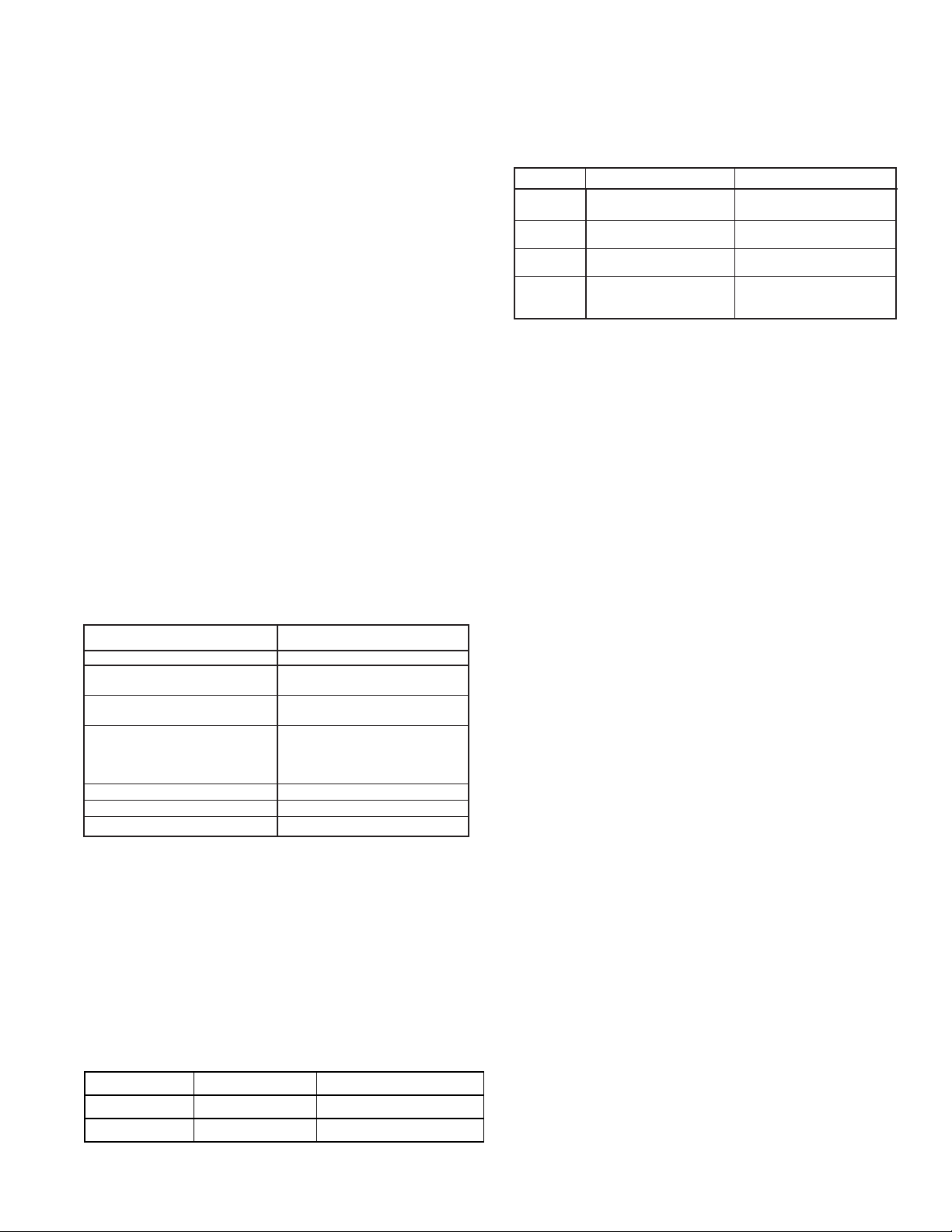
NOTE: A pipe hanger adapter kit, shown in Figure 5.3, is
available as an accessory. One kit consists of two drilled
3/4" IPS pipe caps and two 3/8" - 16 x 1-3/4" capscrews
to facilitate threaded pipe suspension. Two kits would be
required to install one unit.
5c. Shelf mounted units: The unit heater can also be installed
on a shelf. The mounting brackets will need to be attached
to the heater the same manner as explained in note #4,
however, to mount on a shelf the brackets must go on the
bottom of the heater. The brackets must be affixed to the
shelf using similar screws (1/4" screw with 1/2" washer) as
overhead joist or truss mounting. Be sure all clearance to
combustible requirements are met.
Figure 5.3 - Unit Heater Suspension Methods
(Threaded Rod) (Pipe Adaptor Kit)
6-583.9
5
Page 6
INSTALLATION - VENTING
WARNING
1. Gas fired heating equipment must be vented - do not
operate unvented.
2. A built-in power exhauster is provided - additional external
power exhausters are not required or permitted.
3. If an existing heater is being replaced, it may be necessary
to resize the venting systems. Improperly sized venting
systems can result in vent gas leakage or the formation of
condensate. Refer to the National Fuel Gas Code ANSI
Z223.1 (NFPA 54) or CSA-B149.1 Installation Code - latest
edition. Failure to follow these instructions can result in
serious injury or death.
4. Under no circumstances should two sections of double wall
vent pipe be joined together within one horizontal vent system
due to the inability to verify complete seal of inner pipes.
CAUTION
Installation must conform with local building codes or in the
absence of local codes, with the National Fuel Gas Code,
ANSI Z223.1 (NFPA 54) - latest edition. In Canada, installation
must be in accordance with CSA B149.1.
Model HD/HDB unit heaters must be vented with the proper
passageway as described in these instructions to convey
flue gases from the unit or the vent connector to the outside
atmosphere.
The venting instructions are organized in sections, based on
installation type. The sections are identified as follows:
Instructions Applicable Installation Instructions
Section by Vent System Type
A General instructions for ALL installations
B VERTICAL Category I vent systems ➀
C HORIZONTAL Category III vent systems ➀
➀ The difference between Vertical Category I and Horizontal Category III will be
identified in "Section A - General Instructions - All Units".
Section A – General Instructions – All Units
A1. If the unit heater being installed is replacing existing
equipment and using the existing vent system from that
equipment, inspect the venting system for proper size and
horizontal pitch, as required in the National Fuel Gas Code
ANSI Z223.1 (NFPA 54) or CSA-B149.1 Installation Codelatest edition and these instructions. Determine that there
is no blockage or restriction, leakage, corrosion and other
deficiencies which could cause an unsafe condition.
A2. The vent pipe should be galvanized steel or other suitable
corrosion resistant material (except for Horizontal Category
III vent systems, which will be covered in “Section C –
Horizontal, Category III Vent System Installation”). Follow
the National Fuel Gas Code for minimum thickness of vent
material. The minimum thickness for connectors varies
depending on the pipe diameter. Do not vent unit with PVC
or other forms of plastic venting material.
A3. All heaters come with a factory installed vent adapter for
attaching the vent pipe to the heater. Attach the vent pipe
to the adapter with 3 non-corrosive screws. (Drill pilot holes
through the vent pipe and adapter prior to screwing in
place).
A4. Refer to Table 6.1 for total equivalent vent pipe lengths,
making the vent system as straight as possible. The
equivalent length of a 3" elbow is 1' and for a 4" elbow is 5'.
Table 6.1 - Vent Pipe Diameters and Total Equivalent
Vent Pipe Lengths For Horizontal Venting Systems
Model Size Vent Pipe Diameter
30-75 3" 3' 30'
100-125 4" 3' 30'
Minimum
Eqv. Length
A5. A minimum of 12" straight pipe is recommended from the
flue outlet before turns in the vent pipe.
A6. Horizontal sections of vent pipe are to be installed with a
minimum downward slope from the appliance of 1/4 inch
per foot and suspended securely from overhead structures
at points not greater than 3' apart.
A7. Fasten individual lengths of vent together with at least 3
corrosion-resistant sheet metal screws.
A8. Keep single wall vent pipe at least 6" from combustible
materials. For double wall vent pipe, follow the vent
pipe manufacturer’s clearances to combustibles. The
minimum distance from combustible materials is based
on the combustible material surface not exceeding 160°F.
Clearance from the vent pipe (or the top of the unit) may be
required to be greater than 6" if heat damage other than fire
could result (such as material distortion or discoloration).
A9. Avoid venting through unheated space when possible.
When venting does pass through an unheated space or
if the unit is installed in an environment that promotes
condensation, insulate runs greater than 5' to minimize
condensation. Inspect for leakage prior to insulating and
use insulation that is noncombustible with a rating of not
less than 400°F. Install a tee fitting at the low point of the
vent system and provide a drip leg with a clean out cap as
shown in Figure 8.1.
A10. When the vent passes through a combustible INTERIOR
wall or floor, a metal thimble 4" greater than the vent
Maximum
Eqv. Length
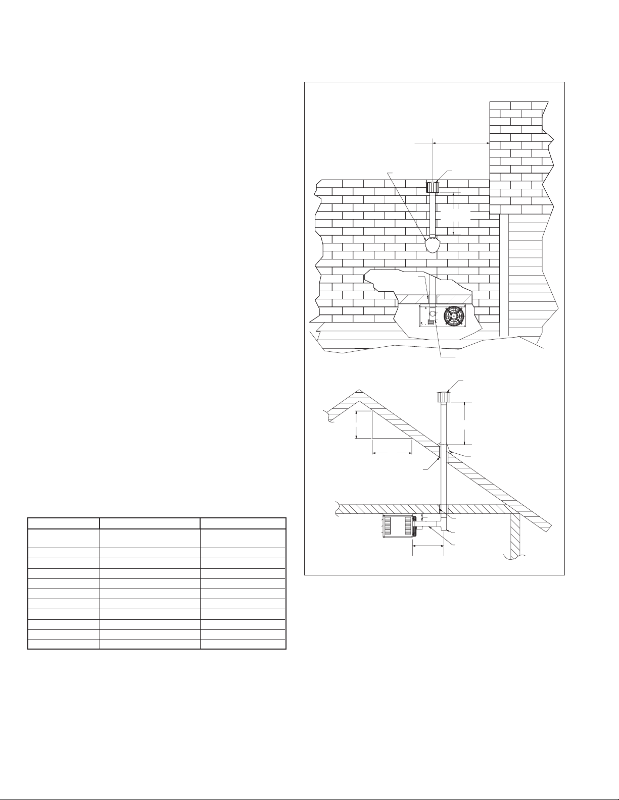
Figure 6.1 - Venting Through Combustible Roof
or Wall
Single Wall Vent Pipe
Flashing
Listed
Thimble
Single
Wall
Non-Residential Single Wall Vent
Pipe Terminating with Double Wall
Vent Pipe ➀
Clearance Specified
by Type B Vent Mfg.
Agency Approved Vent
Kit or Single Wall Vent
Pipe
➀ See Instruction A10 for attaching single wall pipe to double wall pipe
Listed
Thimble
Listed
Terminal
Double Wall Vent Pipe ➀
Flashing
Clearance Specified
by Type B Vent Mfg.
Double
Wall
Single
Wall
Listed
Terminal
Listed
Terminal
Listed
Terminal
6
6-583.9
Page 7
INSTALLATION - VENTING
diameter is necessary. If there is 6' or more of vent pipe in
the open space between the appliance and where the vent
pipe passes through the wall or floor, the thimble need only
be 2" greater than the diameter of the vent pipe. If a
thimble is not used, all combustible material must be cut
away to provide 6" of clearance. Where authorities have
jurisdiction, type B vent may be used for the last section
of vent pipe to maintain clearance to combustibles while
passing through wall or floor (see Figure 6.1). Any material
used to close the opening must be noncombustible.
A11. The following are general instructions for double wall
(type B) terminal pipe installation:
How to attach a single wall vent terminal to double wall
(type B) vent pipe:
1. Look for the “flow” arrow on the vent pipe.
2. Slide the vent terminal inside the exhaust end of the
double wall vent pipe.
3. Drill 3 holes through the pipe and the vent terminal.
Using 3/4" long sheet metal screws, attach the cap to
the pipe. Do not over tighten.
How to connect a single wall vent system to double
wall (type B) vent pipe:
1. Slide the single wall pipe inside the inner wall of the
double wall pipe.
2. Drill 3 holes through both walls of the single and double
wall vent pipes. Using 3/4" sheet metal screws, attach
the two pieces of pipe. Do not over tighten.
3. The gap between the single and double wall pipe must
be sealed, but it is not necessary to fill the full volume
of the annular area. To seal, run a large bead of 400°F
silastic around the gap.
A12. Vent termination clearances must be maintained:
Table 7.1 - Vent Termination Clearances
Minimum Clearances for
Structure Vent Terminal Location
Forced air inlet within 10 feet 3 feet above
Combustion air inlet of another
appliance 6 feet all directions
Door, window, gravity air inlet, 4 feet horizontal and below
or any building opening 1 foot above
Electric meter, gas meter, gas 4 feet horizontal (U.S.)
regulator, and relief equipment ➀ 6 feet horizontal (Canada)
Gas regulator ➀ 3 feet horizontal (U.S.)
6 feet horizontal (Canada)
Adjoining building or parapet wall 6 feet all directions
Adjacent public walkways 7 feet all directions
Grade (ground level) 3 feet above
➀
Do not terminate the vent directly above a gas meter or regulator.
A18. In addition to following these general instructions, specific
instructions for Vertical Category I or Horizontal Category III
vent systems must also be followed. Table 7.3 outlines the
differences:
Table 7.3 - ANSI Unit Heater Venting Requirements
Category Description Venting Requirements
I Negative vent pressure Follow standard
Non-condensing venting requirements.
II Negative vent pressure Condensate must
Condensing be drained.
III Positive vent pressure Vent must be gas tight.
Non-condensing
IV Positive vent pressure Vent must be liquid and
Condensing gastight. Condensate
must be drained.
Note: Vent connectors serving Category I appliances shall not be connected into
any portion of mechanical draft systems operating under positive pressure.
Vertical Category I Vent System Determination
• Verticalventsystemsterminatevertically(up).
• Thehorizontalportionoftheventruncannotexceed75%
of the vertical rise (Example: If the vent height is 10', the
horizontal portion of the vent system cannot exceed 7.5').
• Theventterminatesaminimumof5’abovetheventconnector
on the unit.
• IftheventsystemtobeinstalledmeetsALLthesecriteria
(an example is shown in Figure 9.1), proceed to “Section B –
Vertical Vent System Installation”. For all other cases, proceed
to the next section for Horizontal Category III Vent System
Determination:
Horizontal Category III Vent System Determination
•Horizontalventsystemsterminatehorizontally(sideways).
•Aventsystemthatterminatesverticallybuthasahorizontal
run that exceeds 75% of the vertical rise is considered
horizontal.
Horizontal vent configurations are Category III. For residential
installations, this requires the use of an agency approved
(UL1738) Category III vent system. Additional requirements,
including those for commercial and industrial installations are
covered in “Section C – Horizontal, Category III Vent System
Installation”.
A13. Do NOT use dampers or other devices in the vent or
combustion air pipes.
A14. Precautions must be taken to prevent degradation of
building materials by flue products.
A15. Single wall vent pipe must not pass through any
unoccupied attic, inside wall, concealed space, or floor.
A16. Uninsulated single wall vent pipe must not be used
outdoors for venting appliances in regions where the 99%
winter design temperature is below 32°F.
A17. The vent terminal must be:
Table 7.2 - Vent Terminals
Model Size Modine PN Other Listed Terminals
30-75 5H0722850005 Gary Steel 1092
100-125 5H0722850001 Gary Steel 1092
6-583.9
7
Page 8
INSTALLATION - VENTING
Section B – Vertical Vent System Installation
B1. This section applies to vertically vented Category I
vent systems and is in addition to “Section A – General
Instructions – All Units”.
B2. Vertical vent systems terminate vertically, and must be
sized in accordance with the National Fuel Gas Code, ANSI
Z223.1 (NFPA 54) - latest edition.
B3. The horizontal portion of the vent run cannot exceed 75%
of the vertical rise (Example: If the vent height is 10', the
horizontal portion of the vent system cannot exceed 7.5').
B4. It is recommended to install a tee with drip leg and clean out
cap as shown in Figure 8.1.
B5. The vent terminates a minimum of 5’ above the vent
connector on the unit.
B6. All vertically vented heaters that are Category I must be
connected to a chimney or vent complying with a recognized
standard, or a lined masonry (or concrete) chimney with
a material acceptable to the authority having jurisdiction.
Venting into an unlined masonry chimney is not permitted.
Refer to the National Fuel Gas Code for common venting
and pages 11-12 of this manual.
B7. Use a listed vent terminal to reduce down drafts and
moisture in the vent.
B8. Double wall vent pipe is recommended, although single wall
can be used if the requirements of the National Fuel Gas
Code are followed.
B9. Vertical vents must terminate a minimum horizontal and
vertical distance from roof lines and adjacent walls or
obstructions. These minimum distances are outlined as
follows (based on National Fuel Gas Code requirements for
vents with diameters less than 12”):
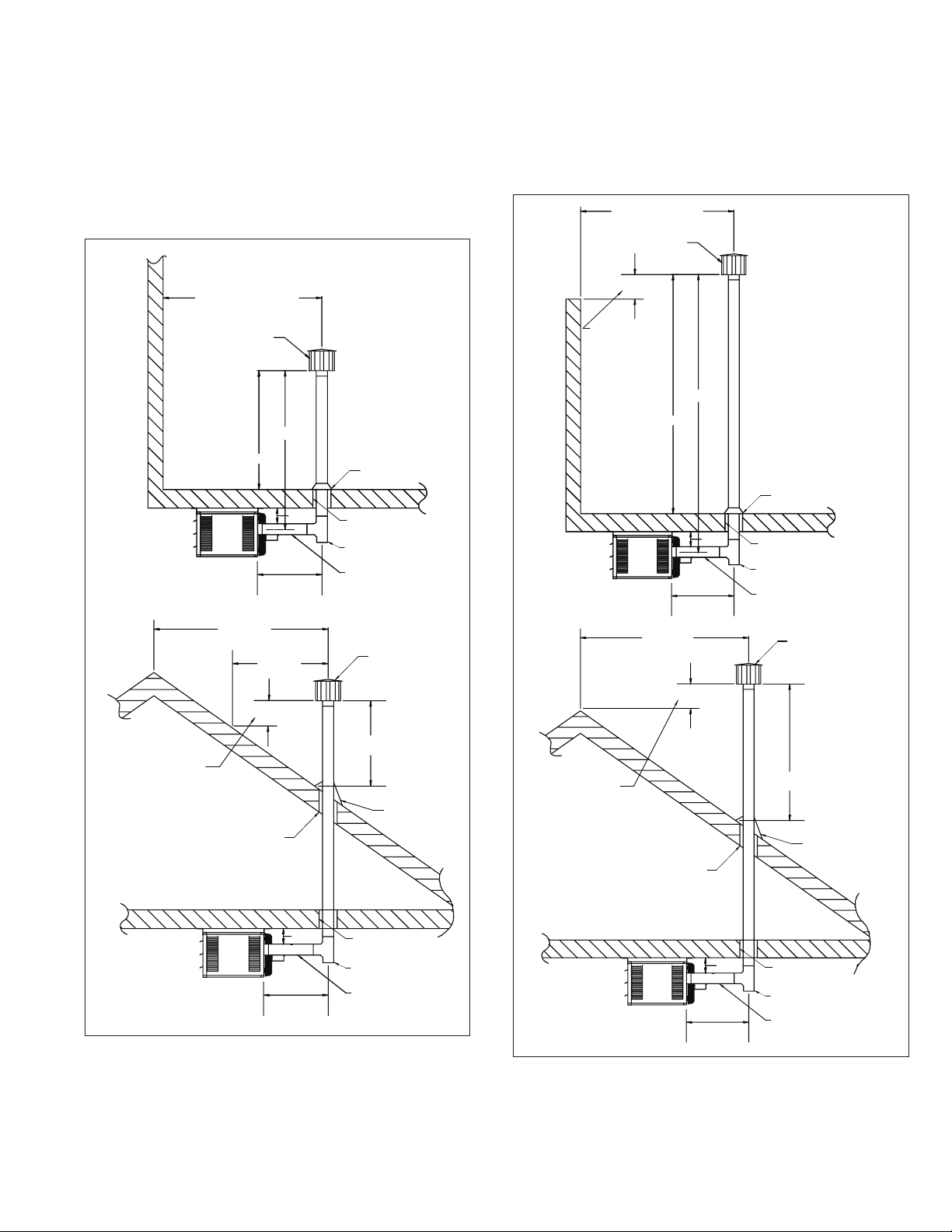
•Fordouble wall vent pipe and 8' or greater horizontal
distance to any vertical wall or similar obstruction, the vent
must terminate above the roof in accordance with Figure
8.1 and Table 8.1.
•Fordouble wall vent pipe and less than 8' horizontal
distance to any vertical wall or similar obstruction, the vent
must terminate at least 2' above the highest point where it
passes through a roof of a building and at least 2' higher
than any portion of a building within a horizontal distance of
10' (see Figure 8.1).
Figure 8.1 - Vertical Vent Termination for Double
Wall Vent Pipe and Greater Than or Less Than 8’
Horizontally From a Vertical Wall or Obstruction
IF DISTANCE TO ADJACENT WALL IS
LESS THAN 8 FEET, THEN VENT MUST
TERMINATE AT LEAST 2 FEET ABOVE
THE HIGHEST POINT OF THE WALL
THAT IS WITHIN 8 FEET HORIZONTAL.
OTHERWISE, REFER TO TABLE 8.1 FOR
"H" DIMENSION.
LISTED TERMINAL
"H" MIN*
(SEE TABLE 8.1)
TEE WITH DRIP LEG
AND CLEANOUT CAP
"H" MIN*
(SEE TABLE 8.1)
LISTED TERMINAL
ROOF FLASHING
X
ROOF PITCH IS:
X / 12
ROOF FLASHING
USE LISTED THIMBLE
THROUGH CEILING
AND ROOF
12
USE LISTED THIMBLE
THROUGH ROOF
Table 8.1 - Minimum Height from Roof to Lowest
Discharge Opening
Rise X (in) Roof Pitch Min Height H (ft) ➀
0-6 Flat to 6/12 1.00
6-7 6/12 to 7/12 1.25
7-8 7/12 to 8/12 1.50
8-9 8/12 to 9/12 2.00
9-10 9/12 to 10/12 2.50
10-11 10/12 to 11/12 3.25
11-12 11/12 to 12/12 4.00
12-14 12/12 to 14/12 5.00
14-16 14/12 to 16/12 6.00
16-18 16/12 to 18/12 7.00
18-20 18/12 to 20/12 7.50
20-21 20/12 to 21/12 8.00
➀ Size according to expected snow depth.
8
6-583.9
BACK VIEW
4" MIN
USE LISTED THIMBLE
THROUGH CEILING
TEE WITH DRIP LEG
AND CLEANOUT CAP
12" MIN
RECOMMENDED
DOWNWARD SLOPE
1/4" PER FOOT
TOWARD DRIP LEG
Page 9
INSTALLATION - VENTING
•Forsingle wall vent pipe and 10' or greater horizontal
distance to any portion of a building, the vent must terminate at
least 3' (2' for non-residential installations) above the highest
point where it passes through a roof of a building and at least 2'
higher than any portion of a building within a horizontal distance
of 10' (see Figure 9.1).
Figure 9.1 - Vertical Vent Termination for Single Wall
Vent Pipe and Greater Than 10’ Horizontally From
Adjacent Wall or Building
•Forsingle wall vent pipe and less than 10' horizontal distance
to any portion of a building, the vent must terminate 2' higher
than any portion of that building (see Figure 9.2).
Figure 9.2 - Vertical Vent Termination for Single Wall
Vent Pipe and 10’ or Less Horizontally From Adjacent
Building or Building
10 FEET OR LESS TO
WALL OR ADJOINING
BUILDING
LISTED
TERMINAL
GREATER THAN 10 FEET
TO WALL OR ADJOINING
BUILDING
LISTED
TERMINAL
5 FEET MIN
3 FEET MIN*
12" MIN
RECOMMENDED
GREATER
THAN 10 FEET
10 FEET
2 FEET MIN*
4" MIN
ROOF FLASHING
USE LISTED THIMBLE
THROUGH CEILING
TEE WITH DRIP LEG
AND CLEANOUT CAP
DOWNWARD SLOPE
1/4" PER FOOT
TOWARD DRIP LEG
LISTED TERMINAL
2 FEET MIN*
HEIGHT ABOVE ANY
PORTION OF WALL OR
ADJOINING BUILDING
WITHIN 10 FEET
3 FEET MIN*
10 FEET OR
LESS
5 FEET MIN
4" MIN
12" MIN
RECOMMENDED
2 FEET MIN*
ROOF FLASHING
USE LISTED THIMBLE
THROUGH CEILING
TEE WITH DRIP LEG
AND CLEANOUT CAP
DOWNWARD SLOPE
1/4" PER FOOT
TOWARD DRIP LEG
LISTED TERMINAL
HEIGHT ABOVE
ANY ROOF SURFACE
WITHIN 10 FEET
* 2 FEET MINIMUM FOR
NON-RESIDENTIAL
INSTALLATIONS, BUT
SIZE ACCORDING TO
EXPECTED SNOW DEPTH
USE LISTED THIMBLE
THROUGH ROOF
4" MIN
12" MIN
RECOMMENDED
3 FEET MIN*
ROOF FLASHING
USE LISTED THIMBLE
THROUGH CEILING
TEE WITH DRIP LEG
AND CLEANOUT CAP
DOWNWARD SLOPE
1/4" PER FOOT
TOWARD DRIP LEG
HEIGHT ABOVE
ANY ROOF SURFACE
WITHIN 10 FEET
* 2 FEET MINIMUM FOR
NON-RESIDENTIAL
INSTALLATIONS, BUT
SIZE ACCORDING TO
EXPECTED SNOW DEPTH
USE LISTED THIMBLE
THROUGH ROOF
RECOMMENDED
4" MIN
12" MIN
3 FEET MIN*
ROOF FLASHING
USE LISTED THIMBLE
THROUGH CEILING
TEE WITH DRIP LEG
AND CLEANOUT CAP
DOWNWARD SLOPE
1/4" PER FOOT
TOWARD DRIP LEG
B10. Once venting is complete, proceed to the section titled
“Installation – Gas Connections”.
6-583.9
9
Page 10
INSTALLATION - VENTING
Section C – Horizontal, Category III Vent System
Installation
C1. This section applies to horizontally vented Category III
vent systems and is in addition to “Section A – General
Instructions – All Units”.
C2. All heaters that are horizontally vented perform as a
Category III appliance. Category III venting has special
venting requirements as follows:
•Allresidential, horizontally vented Category III heaters
must be vented with an agency certified (UL1738)
Category III venting system. Agency certified Category
III venting systems are available from your local vent pipe
distributor. Follow the agency certified Category III vent
manufacturer's instructions for installation.
•Forcommercial and industrial horizontally vented
heaters you may use either agency certified Category III
venting systems as noted above, or single wall galvanized
or stainless steel vent pipe. For single wall vent systems,
one continuous section of double wall vent pipe may be
used within the vent system to pass through the wall to
the listed terminal. Refer to instruction A10 in “Section
A – General Instructions – All Units” for attaching double
wall pipe to single wall pipe. If single wall vent pipe is used,
all seams and joints must be sealed with metallic tape or
silastic suitable for temperatures up to 400°F. Wrap the
tape 2 full turns around the vent pipe.
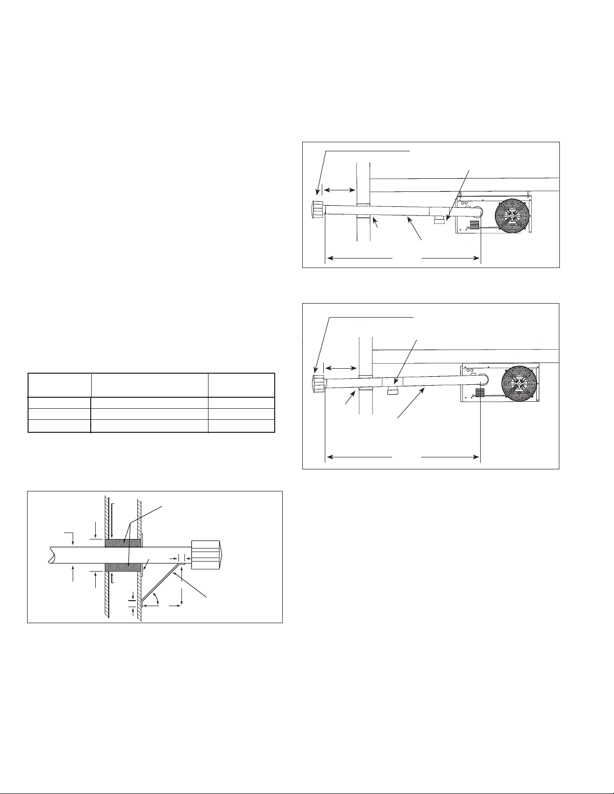
C3. All horizontal Category III vents must be terminated with a
listed vent cap. The cap must terminate a minimum distance
from the external wall, as summarized in Table 10.1.
Table 10.1 - Minimum Length Between External
Wall and Vent
Model Min. Length
Size Application A ➀
30-75 Residential & Commercial 11"
100, 125 Residential 12"
100, 125 Commercial 24"
➀
Refer to Figure 10.2 and 10.3.
C4. The vent must be supported as shown in Figure 10.1.
Figure 10.1 - Exhaust Vent Construction Through
Combustible Walls and Support Bracket
PLATE
FIBER GLASS
INSULATION
MIN. 2"
1"
VENT PIPE
DIAMETER
2" MIN.
METAL
SLEEVE
METAL FACE
C7. When vented horizontally, maintain a 1/4" per foot rise away
from the heater and place a drip leg with clean out near the
unit as shown in Figure 10.2. Where local authorities have
jurisdiction, a 1/4" per foot downward slope is acceptable
with a drip leg and clean out near the exit of the vent as
shown in Figure 10.3, or allow the condensate to drip out
the end.
Figure 10.2 - Horizontal Category III Venting with
Upward Pitch
Listed Terminal
Drip leg / Clean out cap
A
6" Above
snow
grade
Listed Thimble
1
/4" Slope per foot up towards termination
3' Min
30' Max
Figure 10.3 - Horizontal Category III Venting with
Downward Pitch (with drip leg)
Listed Terminal
Drip leg / Clean out cap
A
Listed
Thimble
1
/4" Slope per foot down towards termination
3' Min
30' Max
C8. For a vent termination located under an eave, the distance
of the overhang must not exceed 24". The clearance to
combustibles above the exterior vent must be maintained
at a minimum of 12". Consult the National Fuel Gas Code
for additional requirements for eaves that have ventilation
openings.
C9. Once venting is complete, proceed to the section titled
“Installation – Gas Connections”.
2" MIN.
METAL
SLEEVE
45
1"
9"
VENT TERMINATION
SUPPORT BRACKET
9"
(where required)
(Make from 1" x 1" steel angle)
C5. When condensation may be a problem, the vent system
shall not terminate over public walkways or over an area
where condensate or vapor could create a nuisance or
hazard or could be detrimental to the operation of regulators,
relief openings, or other equipment.
C6. The venting system must be exclusive to a single unit, and
no other unit is allowed to be vented into it.
10
6-583.9
Page 11
INSTALLATION - VENTING
USE THIMBLE
THROUGH CELLING
TEE WITH DRIP
LEG AND
CLEANOUT CAP
RECOMENDED
LISTED TERMINAL
UPWARD SLOPE VENT
1/4" PER FOOT TOWARDS DRIP LEG
USE LISTED
THIMBLE
FLASHING
CATEGORY I APPLIANCE
TYPE B DOUBLE WALL
VENT CONNECTOR
TYPE B DOUBLE WALL
COMMON VENT
12" MIN.
REC.
3' MAX
VENT HEIGHT
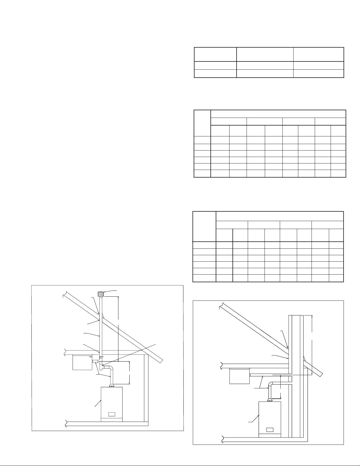
Additional Requirements for Common Venting:
1. The common vent system and all attached appliances must
be Category I.
2. The vent connector should be routed in the most direct
route from the units to the common vent.
3. Where 2 or more vent connectors enter a common gas
vent or chimney flue, the smaller connector shall enter at
the highest level consistent with the available head room or
clearance to combustible material.
4. Restrictions within the common vent such as elbows should
be minimized. Each elbow installed within the common
portion of the venting system reduces maximum common
vent capacity by 10% (refer to Tables 11.2 and 11.3 for
capacity).
5. The vent connector capacities included in these tables allow
for the use of two 90° elbows (or turns). For each additional
elbow, the vent connector capacity shall be reduced by
10%. Refer to NFPA54/ IFEC tables for capacity ratings.
6. The common vent cross sectional area must be equal to or
greater than the largest vent connector cross-sectional area.
7. If all appliances are located on one level of the building, the
vent height shall be measured from the highest draft hood
or vent connector to be installed within the common vent
system (refer to Figures 11.1 and 11.2).
8. All units must be vented in strict accordance of the common
venting Tables 11.1 through 11.3.
9. All masonry chimneys must comply with all applicable local
and national codes.
10. When combining multiple vent connectors into a manifold
prior to the vertical portion of the common vent, the size of
the common vent manifold and the common vent shall be
determined by applying a 10% reduction (.90 x maximum
vent capacity from Table 11.2 or 11.3) to the common vent
capacity part of the common vent tables. The length of the
common vent manifold (Lm) may not exceed 18 inches per
inch of manifold diameter.
11. Refer to the National Fuel Gas Code for instructions on
multi-level common venting and exterior masonry chimneys
as well as additional installation of the listed applications.
Figure 11.1 - Common Venting into Double Wall B Vent
Table 11.1 - Maximum Vent Connector Horizontal
Run (ft) - Type B Vent Connector
Connector
Dia.
3" 30,45,60,75 4.5
4" 100, 125 6
Based on ANSI Z223.1 (NFPA 54)-2009. For reference only.
Model Max Horiz. Run
Table 11.2 - Maximum Total Appliance Input Capacities
(MBh) - Type B Vent Connector and Type B Common
Vent
Diameter of Common Vent
Vent
4 in. 5 in. 6 in. 7 in.
Height
Fan+ Fan+ Fan+ Fan+ Fan+ Fan+ Fan+ Fan+
(ft)
Fan Nat Fan Nat Fan Nat Fan Nat
6 92 81 140 116 204 161 309 248
8 101 90 155 129 224 178 339 275
10 110 97 169 141 243 194 367 299
15 125 112 195 164 283 228 427 352
20 136 123 215 183 314 255 475 394
30 152 138 244 210 361 297 547 459
Based on ANSI Z223.1 (NFPA 54)-2009. For reference only.
Table 11.3 - Maximum Total Appliance Input
Capacities (MBh) - Type B Vent Connector with
Common Vent into Masonry Chimney
Vent
Height
(ft.)
12 in
Fan+
Fan
2
Fan+
Nat
6 NA 74 NA 119 NA 178 NA 257
8 NA 80 NA 130 NA 193 NA 279
10 NA 84 NA 138 NA 207 NA 299
15 NA NA NA 152 NA 233 NA 334
20 NA NA NA NA NA 250 NA 368
30 NA NA NA NA NA 270 NA 404
Based on ANSI Z223.1 (NFPA 54)-2009. For reference only.
Area of Common Vent
2
19 in
Fan+
Fan
Fan+
Nat
28 in
Fan+
Fan
2
Fan+
Nat
38 in
Fan+
Fan
2
Fan+
Nat
Figure 11.2 - Common Venting into Masonry Chimney
6-583.9
MASONRY CHIMNEY
(COMMON VENT)
TYPE B DOUBLE WALL
VENT CONNECTOR
UPWARD SLOPE VENT
1/4" PER FOOT TOWARDS CHIMNEY
CATEGORY I APPLIANCE
FLASHING
3' MAX
CHIMNEY
HEIGHT
11
Page 12
INSTALLATION - GAS CONNECTIONS
WARNING
1. All field gas piping must be pressure/leak tested prior to
operation. Never use an open flame. Use a soap solution or
equivalent for testing.
2. Gas pressure to appliance controls must never exceed
14" W.C. (1/2 psi).
3. To reduce the opportunity for condensation, the minimum
sea level input to the appliance, as indicated on the serial
plate, must not be less than 5% below the rated input, or
5% below the minimum rated input of dual rated units.
CAUTION
1. Purging of air from gas lines should be performed as
described in the National Fuel Gas Code, ANSI Z223.1
(NFPA 54) - latest edition or in Canada CSA-B149 codes.
2. When leak testing the gas supply piping system, the
appliance and its combination gas control must be isolated
during any pressure testing in excess of 14" W.C. (1/2 psi).
3. The unit should be isolated from the gas supply piping
system by closing its field installed manual shut-off valve.
This manual shut-off valve should be located within 6' of
the heater.
4. Turn off all gas before installing appliance.
IMPORTANT
To prevent premature heat exchanger failure, the input to the
appliance, as indicated on the serial plate, must not exceed
the rated input by more than 5%.
1. Installation of piping must conform with local building codes,
or in the absence of local codes, with the National Fuel Gas
Code, ANSI Z223.1 (NFPA 54) - latest edition. In Canada,
installation must be in accordance with CSA-B149.1.
2. Piping to units should conform with local and national
requirements for type and volume of gas handled and
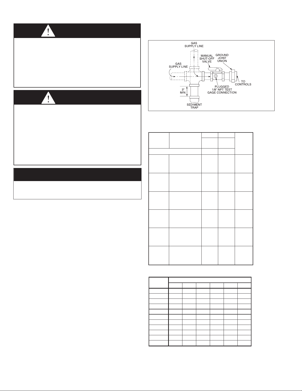
pressure drop allowed in the line. Refer to Table 12.1 to
determine the cubic feet per hour (CFH) for the type of gas
and size of unit to be installed. Using this CFH value and the
length of pipe necessary, determine the pipe diameter from
Table 12.2. Where several units are served by the same
main, the total capacity, CFH, and length of main must be
considered. Avoid pipe sizes smaller than 1/2". Table 12.2
allows for a 0.3" W.C. pressure drop in the supply pressure
from the building main to the unit. The inlet pressure to the unit
must be 6-7" W.C. for natural gas and 11-14" W.C. for propane
gas. When sizing the inlet gas pipe diameter, make sure that
the unit supply pressure can be met after the 0.3" W.C. has
been subtracted. If the 0.3" W.C. pressure drop is too high,
refer to the Gas Engineer’s Handbook for other gas pipe
capacities.
3. Install a ground joint union with brass seat and a manual shutoff valve adjacent to the unit for emergency shut-off and easy
servicing of controls, including a 1/8" NPT plugged tapping
accessible for test gauge connection (see Figure 12.1).
4. Use 2 wrenches when connecting field piping to units.
5. Provide a sediment trap before each unit in the line where low
spots cannot be avoided (see Figure 12.1).
6. When pressure/leak testing, pressures above 14" W.C.
(1/2 psi), close the field installed shut-off valve, disconnect the
appliance and its combination gas control from the gas supply
line, and plug the supply line before testing. When testing
pressures 14" W.C. (1/2 psi) or below, close the manual
shut-off valve on the appliance before testing.
12
Figure 12.1 - Recommended Sediment Trap/Manual
Shut-off Valve Installation - Side or Bottom Gas
Connection
➀ Manual shut-off valve is in the “OFF” position when handle is perpendicular to pipe.
➀
Table 12.1 - Sea Level Manifold Pressure & Gas
Consumption
Natural Propane
Model BTU/Cu. Ft. 1050 2500 No. of
Size Specific Gravity 0.60 1.53 Orifices
Manifold Pressure In. W.C. 3.5 10.0
CFH 28.6 12.0 2
Gal/Hr. Propane .33
30
Sec/cu. ft. 126 300
Orifice Drill Size 49 56
CFH 42.9 18.0 3
Gal/Hr. Propane .50
45
Sec/cu. ft. 84 200
Orifice Drill Size 49 56
CFH 57.1 24.0 4
Gal/Hr. Propane .66
60
Sec/cu. ft. 63 150
Orifice Drill Size 49 56
CFH 71.4 30.0 5
Gal/Hr. Propane .83
75
Sec/cu. ft. 50 180
Orifice Drill Size 49 56
CFH 95.2 40 5
Gal/Hr.Propane 1.09
100
Sec/cu.ft. 38 90
Orifice Drill Size 45 55
CFH 119 50 5
Gal/Hr.Propane 1.37
125
Sec/cu.ft. 30 72
Orifice Drill Size 42 53
Table 12.2 - Gas Pipe Capacities - Natural Gas ➀ ➁
Pipe
Length (ft)
10 132 278 520 1050 1600 3050
20 92 190 350 730 1100 2100
30 73 152 285 590 890 1650
40 63 130 245 500 760 1450
50 56 115 215 440 670 1270
60 50 105 195 400 610 1150
70 46 96 180 370 560 1050
80 43 90 170 350 530 930
100 38 79 150 305 460 870
125 34 72 130 275 410 780
150 31 64 120 250 380 710
➀ Capacities in cubic feet per hour through Schedule 40 pipe with maximum
0.3"W.C. pressure drop with up to 14"W.C. gas pressure. Specific gravity is 0.60 for
natural gas and 1.50 for propane gas.
➁ For pipe capacity with propane gas, divide natural gas capacity by 1.6.
Example: What is the propane gas pipe capacity for 60 feet of 1-1/4" pipe?
The natural gas capacity is 400 CFH. Divide by 1.6 to get 250 CFH for propane gas.
1/2" 3/4" 1" 1-1/4" 1-1/2" 2"
Natural Gas
6-583.9
Page 13
INSTALLATION - HIGH ALTITUDE ACCESSORY KIT
HIGH ALTITUDE ACCESSORY KIT
Modine’s gas-fired equipment standard input ratings are
certified by ETL. For elevations above 2,000', ANSI Z223.1
requires ratings be reduced 4 percent for each 1000'. above sea
level. For units in Canada, CSA requires that ratings be reduced
10 percent at elevations above 2,000'. The high altitude
adjustment instructions and pressure switch kits listed in this
manual are for use with units that will be installed over 2,000'
These methods and kits comply with both ANSI Z223.1 and
CSA requirements.
If a unit is to be installed at higher elevations AND converted from
natural gas to propane gas operation, a propane conversion kit
Manifold Pressure Adjustment
The inlet pressure to the unit must be confirmed to be within
acceptable limits (6-7" W.C. for natural gas and 11-14" W.C.
for propane gas) before opening the shutoff valve or the
combination gas valve may be damaged.
Heaters for use with natural gas have gas valves factory set at
3.5" W.C. manifold pressure at 7.0" W.C. inlet pressure.
Units for use with propane gas are set for 10.0" W.C. manifold
pressure at 14.0" W.C. inlet pressure.
Installation above 2,000' elevation requires adjustment of the
manifold pressure as described.
must be used in conjunction with the pressure adjustment
methods and pressure switch kits listed herein. For the selection
and installation instructions for propane conversion kits, please
see the latest revision of Modine Manual 75-515.
Derated BTU Content Gas and Manifold Pressure
Calculation
Some utility companies may derate the BTU content (heating
value) of the gas provided at altitude to a value other than 1,050
Selection of the Proper Pressure and Kit
To determine the proper manifold pressure at altitude and if
required, the proper combustion air pressure switch kit, the full
model number of the heater, the fuel to be used, and the
altitude the unit will be installed at must be known. Refer to the
unit serial plate or carton label to obtain the necessary
information about the unit.
After obtaining this information, refer to the gas pressure and
selection charts shown in Tables 13.1 through 13.3. The pressure
charts are differentiated by elevation, fuel type, and country
the product is being installed in. The selection charts are
differentiated by product type, altitude and fuel type. If
converting from natural gas to propane gas and operation
at high altitude, both a propane conversion kit and a
pressure switch kit must be used (if applicable). Selection
BTU/ft3 for natural gas or 2,500 BTU/ft3 for propane gas to
allow certain heating appliances to be used with no manifold
pressure adjustments. For this reason it is necessary that the
supplying utility be contacted for detailed information about the
gas type and BTU content (heating value) before operating any
heater. Tables 13.1 and 13.2 show the standard derated heating
values (4% per 1,000' of elevation in the USA and 10% between
2,001' and 4,500' elevation in Canada) of natural and propane
gases at various altitudes. If the utility is supplying gas with
heating values as shown in Tables 13.1 and 13.2, the manifold
pressure should be set to 3.5" W.C for natural gas and 10.0"
W.C. for propane gas.
NOTE: Only the high fire gas pressure need be adjusted, low
fire gas pressure should remain the same.
charts include the proper kit suffix, when required.
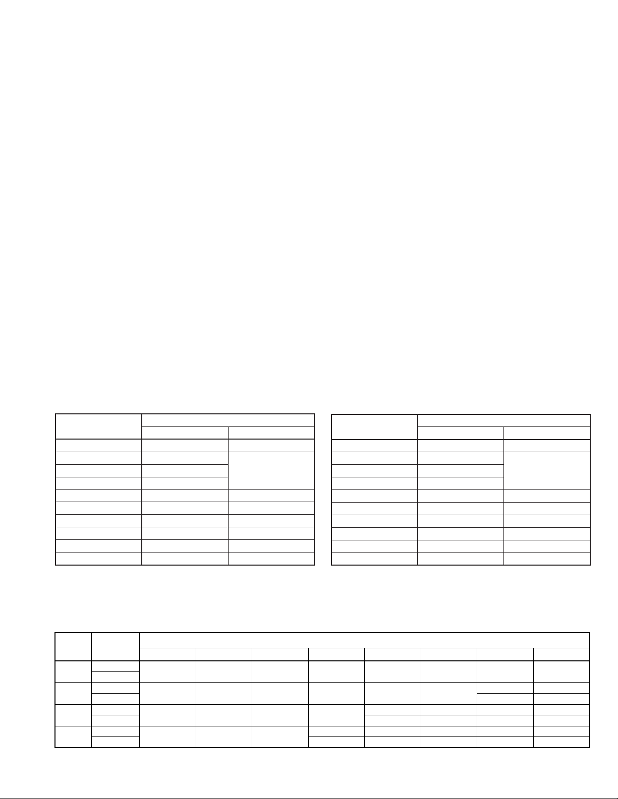
Table 13.1 - Natural Gas Heating Values at
Altitude ➀ ➂ ➃
Altitude (ft)
0-2,000 1,050 1,050
2,001-3,000 929
4,001-4,500 874
4,501-5,000 856 856
5,001-6,000 822 822
6,001-7,000 789 789
7,001-8,000 757 757
8,001-9,000 727 727
9,001-10,000 698 698
➀ Values shown are for 3.5" W.C. manifold pressure, for other BTU content values (available from local utility) use Equation 14.1 to calculate manifold pressure.
➁ Values shown are for 10.0" W.C. manifold pressure, for other BTU content values (available from local utility) use Equation 14.1 to calculate manifold pressure.
➂ When installed at altitudes above 2,000', a pressure switch may need to be changed. Refer to Table 13.3 to determine if a switch change is required.
➃ Gas heating values are derated 4% per 1,000' of elevation in the USA and 10% between 2,000' and 4,500' elevation in Canada in accordance with ANSI Z223.1
and CSA-B149, respectively.
Gas Heating Values at Altitude (BTU/ft3)
USA Canada
9453,001-4,000 892
Table 13.2 - Propane Gas Heating Values at
Altitude ➁ ➂ ➃
Altitude (ft)
0-2,000 2,500 2,500
2,001-3,000 2,212
4,001-4,500 2,080
4,501-5,000 2,038 2,038
5,001-6,000 1,957 1,957
6,001-7,000 1,879 1,879
7,001-8,000 1,803 1,803
8,001-9,000 1,731 1,731
9,001-10,000 1,662 1,662
Gas Heating Values at Altitude (BTU/ft3)
USA Canada
2,2503,001-4,000 2,123
Table 13.3 - High Altitude Kits for HD/HDB ➀
Model
Size
30-60
75
100
125
➀ ForLabelOnlykits,Modinepartnumber5H0807146005isrequiredtobelledoutandattachedtotheunitbytheinstaller.
Please contact the local Modine representative at 1.866.828.4328 (HEAT).
Details
Kit Sufx
Item Code
Kit Sufx
Item Code 68405 68405
Kit Sufx
Item Code 68408 68408 68408 68408
Kit Sufx
Item Code 68408 68408 68408 68408 68408
0-2,000 ft 2,001-4,500 ft 4,501-5,500 ft 5,501-6,500 ft 6,501-7,500 ft 7,501-8,500 ft
Not Required Label Only Label Only Label Only Label Only Label Only Label Only Label Only
Not Required Label Only Label Only Label Only Label Only Label Only
Not Required Label Only Label Only Label Only
Not Required Label Only Label Only
U.S.A and Canada
8,501 - 9,500 ft 9,501-10,000 ft
0001 0001
0004 0004 0004 0004
0004 0004 0004 0004 0004
6-583.9
13
Page 14
INSTALLATION - HIGH ALTITUDE ACCESSORY KIT
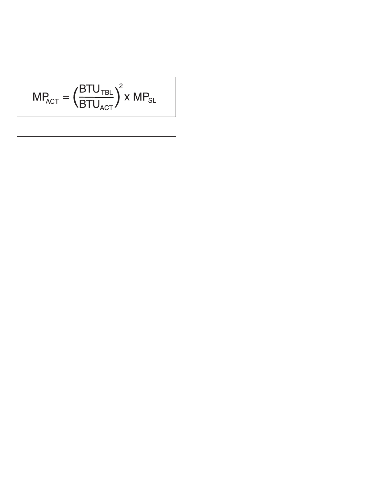
If the heating value of the gas being supplied is different than
the values shown in Tables 13.1 and 13.2, use the following
equation to determine the appropriate manifold pressure for the
altitude and gas heating value being supplied.
Equation 14.1 - Manifold Pressure for Derated Gas
WHERE:
MP
= Manifold Pressure (in. W.C.) at Altitude –
ACT
BTU
BTU
MPSL = Manifold Pressure (in. W.C.), at Sea Level –
NOTE: Only the primary manifold pressure should be adjusted
on units equipped with two-stage or modulating gas controls.
No adjustments to the low fire manifold pressure are necessary
on these units.
Manifold pressure setting for the heater being
installed
= BTU/ft3 Content of Gas –
TBL
Obtained from Tables 13.1 or 13.2 (whichever is
applicable)
= BTU/ft3 Content of Gas –
ACT
Obtained from the local utility company
Use 3.5" W.C. for natural gas and 10.0" W.C. for
propane gas
14
6-583.9
Page 15
INSTALLATION - ELECTRICAL CONNECTIONS
ELECTRICAL CONNECTIONS
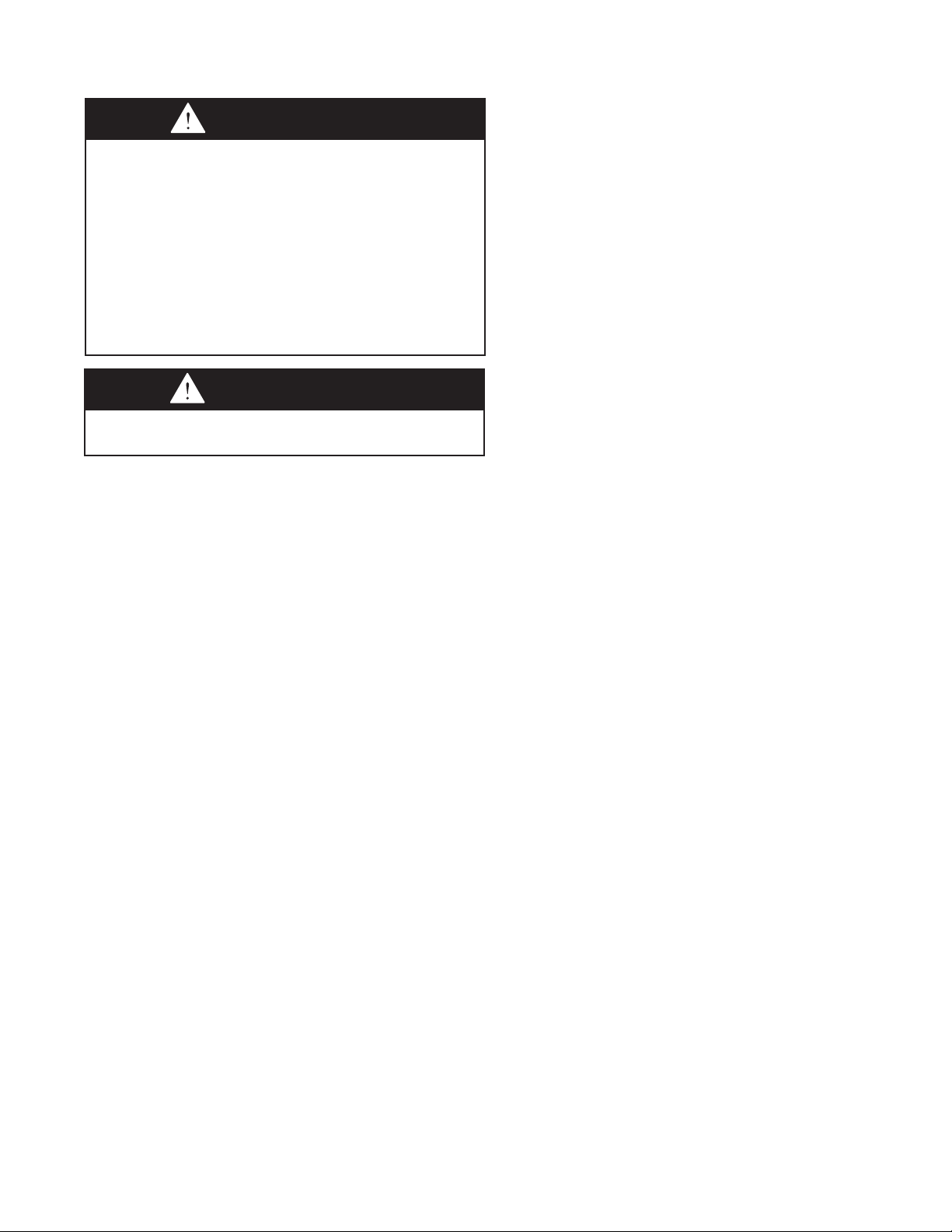
W ARNING
1. Disconnect power supply before making wiring connections
to prevent electrical shock and equipment damage.
2. All appliances must be wired strictly in accordance with
wiring diagram furnished with the appliance. Any wiring
different from the wiring diagram could result in a hazard
to persons and property.
3. Any original factory wiring that requires replacement must
be replaced with wiring material having a temperature
rating of at least 105°C.
4. Ensure that the supply voltage to the appliance, as
indicated on the serial plate, is not 5% greater than rated
voltage.
CAUTION
Ensure that the supply voltage to the appliance, as indicated
on the serial plate, is not 5% less than the rated voltage.
1. Installation of wiring must conform with local building codes,
or in the absence of local codes, with the National Electric
Code ANSI/NFPA 70 - Latest Edition. Unit must be electri cally
grounded in conformance to this code. In Canada, wiring
must comply with CSA C22.1, Part 1, Electrical Code.
2. Two copies of the unit wiring diagram are provided with each
unit. One is located in the side access control compartment
and the other is supplied in the literature packet. Refer to this
diagram for all wiring connections.
3. Make sure all multi-voltage components (motors, transformers, etc.) are wired in accordance with the power supply
voltage.
4. The power supply to the unit must be protected with a fused
or circuit breaker switch.
5. The power supply must be within 5 percent of the voltage
rating and each phase must be balanced within 2 percent of
each other. If not, advise the utility company.
6. External electrical service connections that must be installed
include:
a. Supply power connection (115, 208, 230, 460, or 575 volts).
b. Connection of thermostats, or any other accessory control
devices that may be supplied (24 volts).
NOTE: All units with supply voltage 208V and greater must use
a field installed step-down transformer, available as a separate
accessory. Refer to Table 15.1 for additional information on the
required transformer.
7. Refer to Figures 18.1 and 18.2 for the side access control
compartment location.
8. All supply power electrical connections are made in the side
access control compartment of the unit. The low voltage
(thermostat and accessory control devices) can be wired to
the terminals in the side access control compartment. Refer
to the wiring diagram for the terminal location of all low
voltage wiring.
6-583.9
15
Page 16
INSTALLATION - ELECTRICAL CONNECTIONS
Low Medium High
External Static Pressure (IN. WC)
ELECTRICAL CONNECTIONS
Location of thermostat should be determined by heating
requirements and be mounted on an inside wall about 5' above
floor level where it will not be affected by heat from the unit
or other sources, or drafts from frequently opened doors. See
instructions packed with thermostat.
Wiring Adjustments for Blower Motors
The blowers used on Modine HDB units are direct drive and
equipped with three speed motors. Air temperature rise of the
unit is determined by the speed setting and the amount of static
pressure in the system. Units are normally shipped with motors
set at high speed. Motor speed is changed by connecting the
motor lead for the desired fan speed to the “EAC” or “BLO”
terminal of the control board. Unused motor leads for other
speeds are placed on the “PARK” terminals of the board (see
the wiring diagram on page 21).
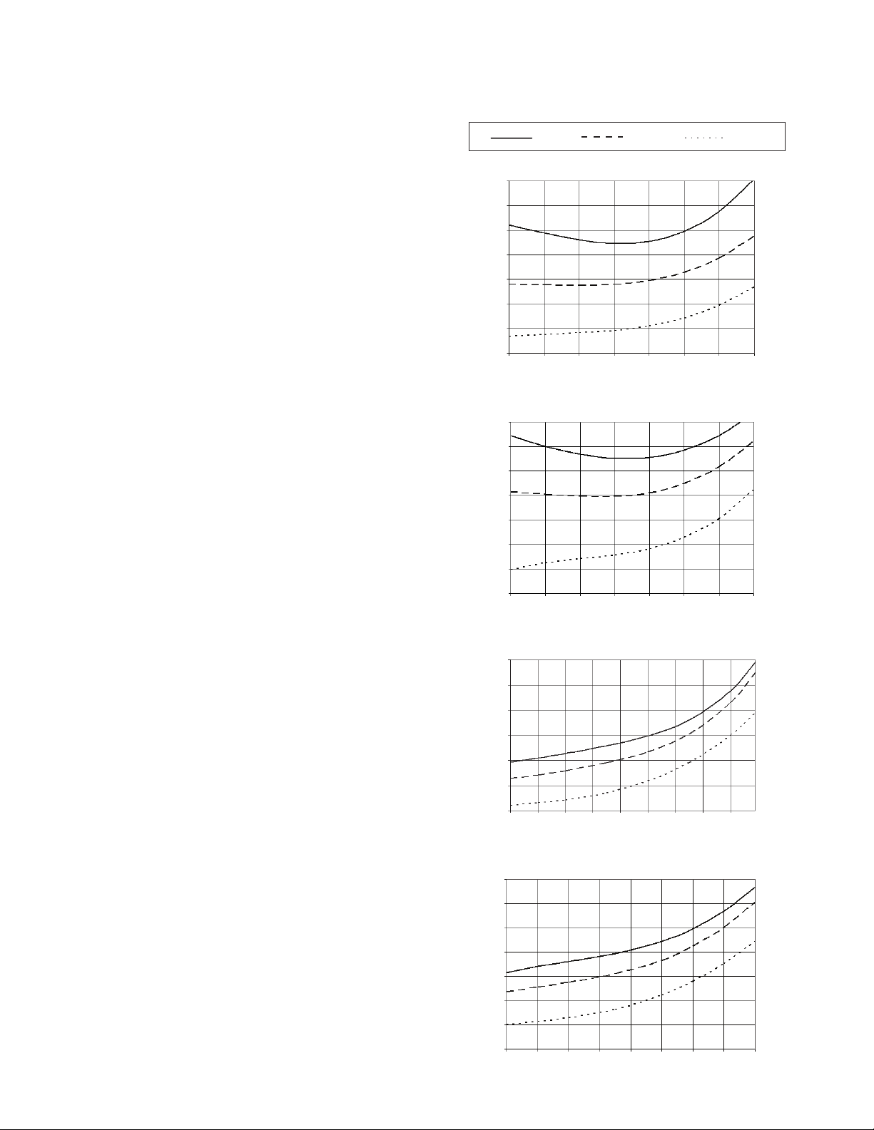
When applying a blower equipped unit to a duct system or
other load, consult the performance curves on this page to
determine the air temperature rise for a given motor speed
range and static pressure. Verify that the static pressure on the
outlet of the unit does not exceed the maximum specified for
the unit. If static pressure is too high it must be reduced either
by modifications to the system or using the medium or low
motor speed. If the unit shuts down on high limit during normal
operation, a higher motor speed should be used.
Blower Curve Models (HDB 60-125 Only)
Speeds
70
65
60
55
50
45
Temperature Rise (Deg. F)
40
35
0.00
0.10
70
65
60
55
50
45
Temperature Rise (Deg. F)
40
35
0.00
0.10
HDB 60
0.30
0.20
External Static Pressure (IN. WC)
0.40
0.50
HDB 75
0.30
0.20
External Static Pressure (IN. WC)
0.40
0.50
0.60
0.60
635
684
741
808
889
988
1111
1270
0.70
794
855
926
1010
1111
1235
1389
1587
0.70
CFM
CFM
65
60
55
50
45
40
Temperature Rise (Deg. F)
35
0.00 0.10 0.20 0.30 0.40 0.50 0.60 0.70 0.80
75
70
65
60
55
50
Temperature Rise (Deg. F)
45
40
0.00 0.10 0.20 0.30 0.40 0.50 0.60 0.70 0.80
HDB 100
HDB 125
External Static Pressure (IN. WC)
1140
1235
1347
1481
1646
1852
2116
1235
1323
1425
1543
1684
1852
2058
2315
CFM
CFM
16
6-583.9
Page 17

INSTALLATION - OPERATION
OPERATION
Prior to Operation
IMPORTANT
1. To prevent premature heat exchanger failure, observe
heat exchanger tubes. If the bottom of the tubes become
red while blower and furnace are in operation, check to be
sure the blower has been set to the proper RPM for the
application. Refer to page 16 for wiring adjustments for
blower motors.
2. Start-up and adjustment procedures must be performed
by a qualified service agency.
Although this unit has been assembled and fire-tested at the
factory, the following pre-operational procedures should be
performed to assure proper on-site operation.
1. Turn off power to the unit at the disconnect switch. Check
that fuses or circuit breakers are in place and sized correctly.
Turn all hand gas valves to the “OFF” position.
2. Remove the side control access panel.
3. Check that the supply voltage matches the unit supply
voltage listed on the Model Identification plate. Verify that
all wiring is secure and properly protected. Trace circuits to
insure that the unit has been wired according to the wiring
diagram. If installed at altitudes above 2,000' and the high
altitude kit includes a combustion air proving switch, replace
the switch in the unit with the switch provided in the kit. Take
care to ensure that the tubing and electrical connections are
securely fastened.
4. Check to insure that the venting system is installed correctly
and free from obstructions. Before you start use the following
steps to verify that the venting system is adequately sized:
a. Seal any unused openings in the venting system.
b. Inspect the venting system for proper size and horizontal
pitch, as required in the National Fuel Gas Code, ANSI
Z223.1 (NFPA 54) or CSA B149.1 Installation Code - latest
edition and these instructions. Determine that there is
no blockage or restriction, leakage, corrosion and other
deficiencies, which could cause an unsafe condition.
c. Insofar as practical, close all building doors and windows
and all doors between the space in which the appliance(s)
connected to the venting system are located and other
spaces of the building. Turn on clothes dryers and any
exhaust fans such as range hoods and bathroom exhausts,
so they shall operate at maximum speed. Do not operate a
summer exhaust fan. Close fireplace dampers.
d. Follow the lighting instructions. Place the appliance being
inspected in operation. Adjust thermostat so that the
appliance will operate continuously.
e. After it has been determined that each appliance connected
to the venting system properly vents when tested as
outlined above, return doors, windows, exhaust fans,
fireplace dampers and any other gas-burning appliance to
their previous conditions of use.
f. If improper venting is observed during any of the above
tests, the venting system must be corrected.
5. Check to see that there are no obstructions to the intake and
discharge of the unit.
6.
Check fan clearance. Fan should not contact casing when
spun by hand.
7. Check to make sure that all filters are in place and that
they are installed properly according to direction of air flow
(if applicable).
8. Perform a visual inspection of the unit to make sure no
damage has occurred during installation. Check to ensure all
fasteners are in place and the burner openings are properly
aligned with the heat exchanger tubes and that the gas orifices
are centered in the burner inspirator tube opening.
9. Check that all horizontal deflector blades are open a minimum
of 30° as measured from vertical.
6-583.9
10. Turn on power to the unit at the disconnect switch.
11. Check the thermostat, ignition control, gas valve, and supply
fan blower motor for electrical operation. If these do not
function, check that the wiring is per the diagram.
12. Check the blower wheel for proper direction of rotation when
compared to the air flow direction arrow on the blower
housing (if applicable). Blower wheel rotation, not air
movement, must be checked as some air will be delivered
through the unit with the blower wheel running backwards.
13. For blower units, check the blower speed (RPM). Refer to
“Blower Adjustments” for modification.
14. Check the motor speed (RPM).
15. Check the motor voltage.
16. Check the motor amp draw to make sure it does not exceed
the motor nameplate rating.
17. Recheck the gas supply pressure at the field installed
manual shut-off valve. The minimum inlet pressure should
be 6" W.C. on natural gas and 11" W.C. on propane gas.
The maximum inlet pressure for either gas is 14" W.C. If
inlet pressure exceeds 14" W.C., a gas pressure regulator
must be added upstream of the combination gas valve.
18. Open the field installed manual gas shut-off valve.
19. Place the manual main gas valve on the combination gas
valve in the “ON” position. Call for heat with the thermostat.
20. Check to make sure that the main gas valve opens. Check
the manifold gas pressure (See “Main Burner Adjustment”)
while the supply fan blower is operating.
21. Check to insure that gas controls sequence properly (see
“Control Operating Sequence”). If you are not familiar with
the unit’s controls (i.e. combination gas control), refer to the
control manufacturer’s literature supplied with the unit.
22. Once proper operation of the unit has been verified,
remove any jumper wires that were required for testing.
24. Replace the side control access panel.
25. If installed at altitudes above 2,000', affix label included with
high altitude kit and fill in all fields with a permanent marker.
Main Burner Adjustment
The gas pressure regulator (integral to the combination gas
control) is adjusted at the factory for average gas conditions. It is
important that gas be supplied to the unit heater in accordance
with the input rating on the serial plate. Actual input should be
checked and necessary adjustments made after the unit heater is
installed. Over-firing, a result of too high an input, reduces the
life of the appliance and increases maintenance. Under no
circumstances should the input exceed that shown on the serial
plate.Measuring the manifold pressure is done at the outlet
pressure tap of the gas valve.
To Adjust the Manifold Pressure
1. Move the field installed manual shut-off valve to the “OFF”
position.
2. Remove the 1/8" pipe plug from the outlet pressure tap on
the gas valve and attach a water manometer of “U” tube type
which is at least 12" high.
3. Move the field installed manual gas shut-off valve to the “ON”
position.
4. Create a high-fire call for heat from the thermostat.
5. Refer to Table 12.1 to determine the correct high fire manifold
pressure for the gas type of the unit. Pressures at 0-2,000'
elevation are 3.5" W.C. for natural gas, 10" W.C. for propane
gas, for elevations above 2,000' refer to the instructions on
page 13. Adjust the main gas pressure regulator spring to
achieve the proper manifold pressure (for location, see the
combination gas control literature supplied with unit).
6. After adjustment, move the field installed manual shut-off valve
to the “OFF” position and replace the 1/8" pipe plug.
7. After the plug is in place, move the field installed manual shut-
off valve to the “ON” position and recheck pipe plugs for gas
leaks with soap solution.
17
Page 18
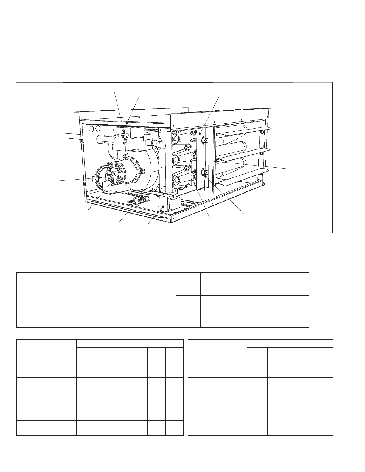
CONTROL OPERATING SEQUENCE / UNIT COMPONENTS
CONTROL OPERATING SEQUENCE
Upon a call for heat from the thermostat, power is supplied to
the power exhauster motor. The unit will go through a purge
period and then the direct spark igniter will be energized. At the
same time, the main valve in the combination control valve will
open to allow gas to flow to the burners. If the fan motor has not
Figure 18.1 - Major Gas, Electrical Service, Safety and Other Components
all ready started it will start shortly. If a flame is not sensed for
any reason the main valve will close and there will be a short
purge period before ignition is tried again. If the flame is not
sensed after 4 tries, there will be at least a 1 hour wait before
ignition is tried again.
➁
➀
1. Power Exhauster
2. Pressure Switch
3. Integrated Direct Spark Control Board
4. Combination Gas Control
➃
➉
➂
5. Control Transformer
6. Flame Sensor (hidden)
7. Flame Rollout Switch
8. Auto Reset Limit Control (hidden)
➄
➈
➅
➇
➆
9. Direct Spark Igniter (hidden)
10. Manual Reset Control (hidden,
propeller 100-125 only)
Table 18.1 - Control Options
Code No. Voltage Voltage Gas Size
Single-Stage, Direct Spark Ignition, 100% Shut-Off with Continuous Retry 11 115V 24V Natural 30-125
- Utilizes a single-stage combination gas control with ignition control. Gas is lit with a
direct spark igniter on call for heat. 21 115V 24V Propane 30-125
Two-Stage, Direct Spark Ignition, 100% Shut-Off with Continuous Retry 12 115V 24V Natural 75-125
- Utilizes a two-stage combination gas control with built-in ignition control.
Firing rate is 100% and 50% of full rated input. Gas is lit with a direct spark
igniter on call for heat.
Control Description
Table 18.2 - Propeller Model HD Performance
30 45 60 75 100 125
Btu/Hr Input 30,000 45,000 60,000 75,000 100,000 125,000
Btu/Hr Output 24,600 36,900 49,200 61,500 82,000 102,500
Entering Airow (CFM) @ 70°F 505 720 990 1160 1490 1980
Outlet Velocity (FPM) 523 725 653 769 565 747
Air Temp. Rise (°F) 44 46 45 48 50 47
Max. Mounting Height (Ft.) 10 10 12 14 12 16
Heat Throw (Ft.)
(@ Max Mtg Ht.)
Motor Type SP SP PSC PSC SP PSC
Motor HP 1/15 1/15 1/12 1/12 1/6 1/8
Motor RPM 1550 1550 1625 1625 1050 1625
18
25 27 36 38 42 56
Control Service Thermostat Type of Model
22 115V 24V Propane 75-125
Table 18.3 - Blower Model HDB Performance
Model HD Sizes
6-583.9
60 75 100 125
Btu/Hr Input
Btu/Hr Output
Entering Airow Range (CFM) 635-1111 794-1389 1140-2116 1235-2058
Outlet Velocity (FPM) 437-726 546-908 443-781 488-773
Air Temp. Rise (°F) 40-70 40-70 35-65 45-75
Max. Mounting Height (Ft.)
Heat Throw (Ft.)
(@ Max Mtg Ht.)
Motor Type
Motor HP 1/4 1/3 1/2 1/2
Motor RPM Max 1100 Max 1100 Max 1100 Max 1100
Ratings shown are for elevations up to 2,000 feet. For elevations above 2,000 feet,
ratings should be reduced at the rate of 4% for each 1,000 feet above sea level. (In
Canada see rating plate.) Reduction of ratings requires use of a high altitude kit.
Data taken at 55°F air temperature rise. At 65°F ambient and unit fired at full-rated
input. Mounting height as measured from bottom of unit, and without deflector hoods.
60,000 75,000 100,000 125,000
49,200 61,500 82,000 102,500
7-13 7-16 8-19 8-17
20-45 24-57 27-68 27-59
P.S.C. P.S.C. P.S.C. P.S.C.
Model HDB Sizes
Page 19
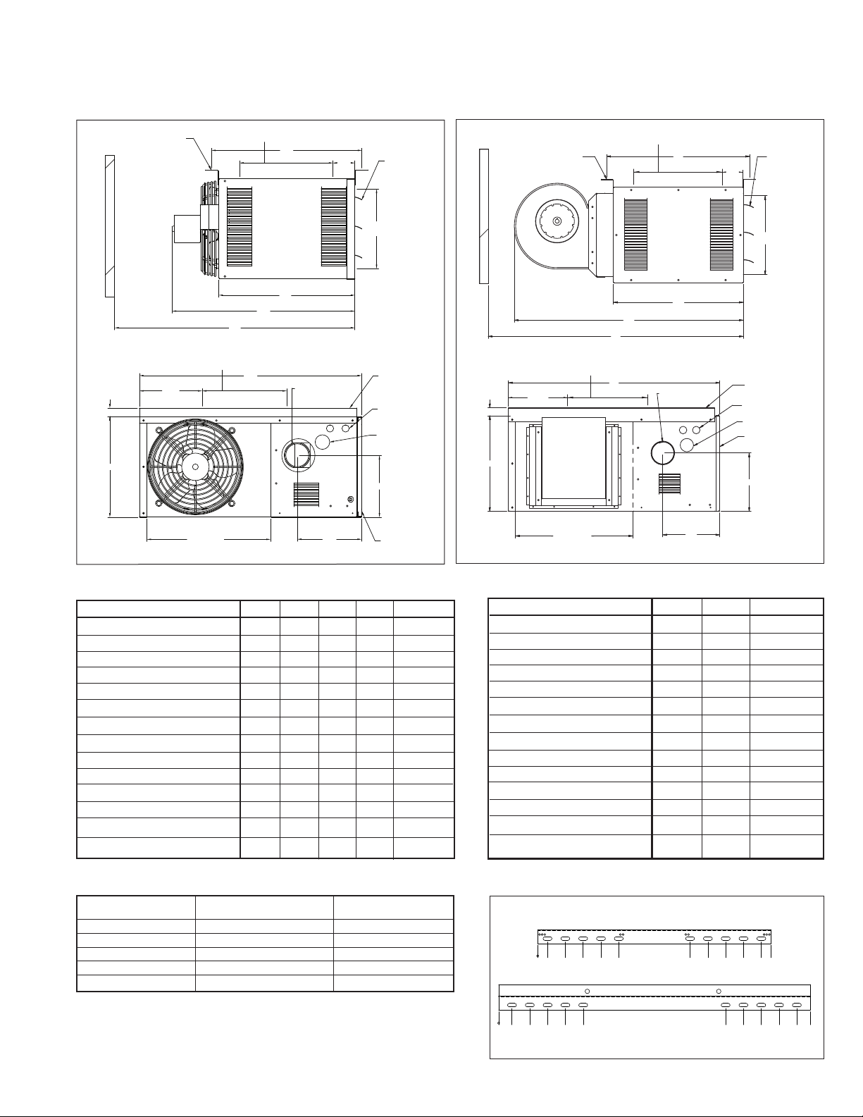
REAR VIEW
DIMENSIONAL DATA - MODEL HD/HDB
Propeller Units - Model HD
Figure 19.1 - Dimensional Drawings - Model HD
14.9" BETWEEN 3/8"-16 MOUNTING HOLES
MOUNTING HOLES TYP
3/8 x 1" LONG
1.00
B
10"
(MODEL SIZES 100 AND 125 ONLY)
I
13.5" BETWEEN 3/8"-16 MOUNTING HOLES
(MODEL SIZES 100 AND 125 ONLY)
G
C
J
ACCESS VIEW
A
POWER VENTER
VENT PIPE
CONNECTION
3.5"
E
OPENING
F
ADJUSTABLE
LOUVERS
MOUNTING
BRACKET
SIZE 30-75
ELECTRICAL
CONNECTION
GAS
CONNECTION
Blower Units - Model HDB
Figure 19.2 - Dimensional Drawings - Model HDB
14.9" BETWEEN 3/8"-16 MOUNTING HOLES
(MODEL SIZES 100 AND 125 ONLY)
1.0"
B
MOUNTING HOLES TYP
3/8 X 1" LONG
14.9" BETWEEN 3/8"-16 MOUNTING HOLES
(MODEL SIZES 100 AND 125 ONLY)
10.0"
J
I
ACCESS VIEW
A
G
C
POWER VENTER
VENT PIPE
CONNECTION
3.5"
E
OPENING
MOUNTING
BRACKETS
SIZE 30-75
ELECTRICAL
CONNECTIONS
GAS
CONNECTION
ACCESS
PANEL
F
ADJUSTABLE
LOUVERS
D OPENING
REAR VIEW
Table 19.1 - Dimensions (inches) - HD
Models
A
B
C
D
E
F
G
H
Gas Connection
I
J
Fan Diameter
Approx. Shipping Weight (lbs.)
Vent Connector Size (in)
HD30 HD45 HD60 HD75 HD100/125
26.8 26.8 26.8 26.8 35.5
12.2 12.2 18.0 18.0 20.5
16.5 16.5 16.5 16.5 22.0
14.9 14.9 14.9 14.9 22.5
10.1 10.1 15.9 15.9 18.4
7.5 7.5 10.7 10.7 14.0
18.5 18.5 18.5 18.5 -
7.6 7.6 7.8 7.8 8.4
1/2 1/2 1/2 1/2 1/2
34.5 34.5 34.5 34.5 43.0
22 22 25 25 31.0
10 10 14 14 18.0
55 60 80 85 125
3 3 3 3 4
H
ACCESS
PANEL
Table 19.2 - Dimensions (inches) - HDB
Approx.Shipping Weight (lbs.)
Vent Connector Size (in)
D OPENING
Models
A
B
C
D
E
F
G
H
Gas Connection
I
J
Blower
Table 19.3 - Clearance to Combustibles, Model HD/HDB Figure 19.3 - Mounting
Unit Side
Combustible Materials Service Clearance
Top and Bottom 1" 1"
Access Side 1" 18"
Non-Access Side 1" 1"
Rear 18" 18"
Vent Connector 4" 4"
Clearance To Recommended
Mounting brackets are slotted to accomodate
joists on 16" or 24" centerlines.
.00
1.10
3.10
5.10
7.10
9.10
H
HDB60 HDB75 HDB100/125
26.8 26.8 35.5
18.0 18.0 20.5
16.5 16.5 22.0
14.9 14.9 22.5
15.9 15.9 18.4
10.7 10.7 14.0
18.5 18.5 -
7.8 7.8 8.4
1/2 1/2 1/2
34.5 34.5 44.5
25.0 25.0 41.5
9 - 7 9 - 7 10 - 10
92 97 151
3 3 4
HD/HDB
30-75
21.10
19.10
17.10
23.10
25.10
26.20
6-583.9
HD/HDB
.00
1.50
5.50
7.50
3.50
9.50
100/125
(Accessory)
25.50
27.50
29.50
31.50
33.50
35.00
19
Page 20
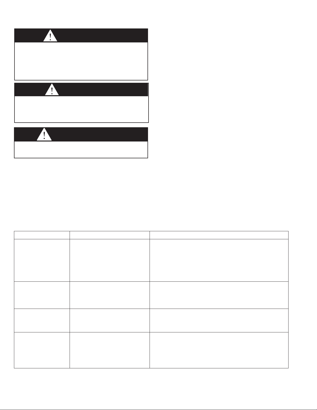
SERVICE / MAINTENANCE / TROUBLESHOOTING
1. Service air moving components annually.
WARNING
When servicing or repairing this equipment, use only factoryapproved service replacement parts. A complete replacement
parts list may be obtained by contacting the factory. Refer
to the rating plate on the appliance for complete appliance
model number, serial number, and company address. Any
substitution of parts or controls not approved by the factory
will be at the owner’s risk.
CAUTION
1. Service or repair of this equipment must be performed by a
qualified service agency.
2. Do not attempt to reuse any mechanical or electrical
controllers which have been wet. Replace defective controller.
IMPORTANT
To check most of the Possible Remedies in the troubleshooting
guide listed in Table 20.1, refer to the applicable sections of
the manual.
General Maintenance
The unit and venting system must be checked once a year by a
qualified service technician.
All installation and service of these units must be
performed by a qualified installation and service agency.
Before any service, BE SURE TO TURN OFF GAS AT THE
MANUAL SHUT-OFF VALVE AHEAD OF THE COMBINATION
GAS CONTROL AND TURN OFF ALL ELECTRIC POWER TO
THE HEATER.
a. Check fan for fit on motor shaft and for damage to blades.
2. Keep unit free from dust, dirt, grease, and foreign matter,
paying particular attention to:
a. Combustion air inlets.
b. Burners and burner orifices. Turn off gas ahead of the
combination gas control and shut off electric power to
the heater. Remove the access panel, open the union
on the gas line, and disconnect the igniter and sensor
wires. Remove the screws that attach the burner tray to
the header plate and remove the burner tray and manifold
assembly from the heater. Carefully clean the burners
with a wire brush or other suitable means. Replace any
damaged or deteriorating burners or orifices. Install the
burner assembly back on to the header making certain that
all screws, pipes and electrical connections are tight.
CAUTION: Be careful when handling the igniter and flame
sensor.
3. Inspect the flame sensor and igniter for deterioration and/or
cracks.
4. Verify that the burners are touching each other at the
carryover points. This will ensure flame carryover from burner
to burner.
a. Clean exterior of heat exchanger tubes.
b. Fan blades.
5. Check wiring for possible loose connections.
6. Controls – The gas valves and piping should be checked
annually for general cleanliness and tightness. The gas
controls should be checked to insure that the unit is operating
properly. See control instruction sheets furnished separately
with the unit heater.
7. Power exhaust assembly/motor – The power exhaust motor
bearings have been lubricated for long life and do not
require additional lubrication. In dirty environments, it may be
desirable to clean the motors and blower housing and blow
out the cooling air passages of the motor with compressed air.
8. Perform periodic cleaning of inlet and vent terminal screens.
Table 20.1 - Troubleshooting
TROUBLE POSSIBLE CAUSE POSSIBLE REMEDY
Unit does nothing 1. Power supply is off 1. Turn on main power
2. No 24V power to thermostat 2 a. Check control transformer
b. If failed transformer - check thermostat wire gage and length
3. Thermostat malfunction 3 a. Verify wire connections to R&W terminals only
b. Check / replace thermostat
4. LED flashes 4. Check LED flash code
5. Blown fuse on control board 5. Replace fuse
6. Defective control 6. Replace control
LED light off or 1. Blown fuse on control board 1. Replace fuse
flashing 2. Multiple causes 2. Control board LED flash codes vary with control type. A decal is
installed in the unit giving a brief description of the applicable codes
for your heater. For more detail, see the control board data sheet
included with the unit.
Unit starts but does 1. Main gas is off 1. Open manual gas valve
not ignite 2. Air in gas line 2. Purge gas line
3. Main or manifold gas pressure 3. Set gas pressures per manual instructions
4. Check gas valve switch 4. Set gas valve switch to “ON” position
Unit goes through cycle 1. Reversed main power polarity 1. Black wire - HOT, White wire - NEUTRAL, Green wire - GROUND
but the burners go out 2. Unit not grounded 2. Ground unit and verify quality of ground connection
in less then 10 seconds 3. Flame not sensed 3. Check flame sense probe and connection
Air circulating fan 1. Loose connections 1. Check all connections
inoperable 2. Defective control board 2. Check control board data sheet and function
3. Defective fan motor 3. Check fan motor
20
6-583.9
Page 21
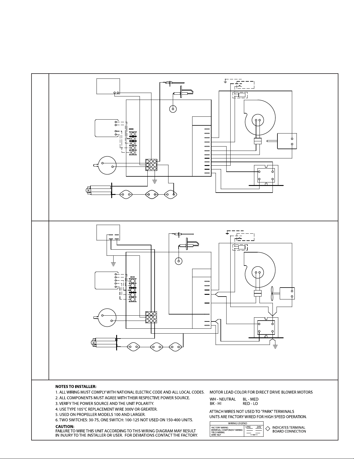
UNIT WIRING
Wiring Diagram Selection
Since internal or factory wiring may vary depending on
the controls manufacturer, the wiring diagrams must be
appropriately selected with the proper gas valve and ignition
Figure 21.1 - Unit Heater Wiring Diagram (Single and Two Stage, Direct Spark Ignition)
GAS
VALV E
type. The following wiring diagram represents a unit equipped
with a single or two stage gas valve and direct spark ignition.
FLAME
SENSOR
SPARK
IGNITOR
GND
GR, (G)
L2, (WH)
115V/60HZ/1Ø POWER
L1, (BK)
CIRCUIT BREAKER (BY OTHERS)
SWITCH
REFER NOTE 7
MULTIPLE RETRY W/AUTO RESET FROM LOCKOUT
SINGLE STAGE, DIRECT SPARK IGNITION, 100% SHUTOFF,
CALL FOR FAN
CALL FOR HEAT
LOW VOLTAGE
THERMOSTAT
(BY OTHERS)
PRESSURE
SWITCH
LIMIT
CONTROL
WHITE ROGERS
GAS VALVE
CALL FOR FAN
1ST STAGE
2ND STAGE
LOW VOLTAGE
THERMOSTAT
(BY OTHERS)
PRESSURE
SWITCH
LIMIT CONTROL
COM
COM
HIM
IGNITION
CONTROL
O
BL
WH
Y
G
W
R
C
PIN 5
Y
Y
PIN 6
(SEE NOTE 5)
PIN 8
Y
Y
1 4 7
852
3 6 9
R
FLAME ROLLOUTS
(SEE NOTE 6)
SINGLE STAGE, DIRECT SPARK IGNITION,
SHUT-OFF, MULTIPLE RETRY W/ AUTO RESET FROM LOCKOUT
BL
WH
Y
G
W1
W2
C
R
1 4 7
852
3 6 9
R
R
O
R
LABEL
PARK
PARK
EAC
IND
SEC
COM
FLAME
SENSOR
IGNITION
CONTROL
LABEL
PARK
PARK
HEAT
IND
24V
COM
UT
L1
L1
IGNITOR
UT
L1
FS
N
E
U
T
R
A
L
SPARK
PE
BK
L1, (BK)
L2, (WH)
R
Y
BK
L1, (BK)
L2, (WH)
R
Y
MOTOR
FAN
MOTOR
WH
BK
SWITCH
WH
BK
120
COM
24
GND
115V/60HZ/1Ø POWER
L2, (WH)
CIRCUIT BREAKER (BY OTHERS)
L1, (BK)
REFER NOTE 7
PE
MOTOR
120
COM
24
XFMR
FAN
MOTOR
XFMR
MULTIPLE RETRY W/AUTO RESET FROM LOCKOUT
TWO STAGE, DIRECT SPARK IGNITION, 100% SHUTOFF,
LIMIT
CONTROL
LIMIT CONTROL
(SEE NOTE 5)
100% SHUT-OFF, MULTIPLE RETRY W/ AUTO RESET FROM LOCKOUT
FLAME ROLLOUTS
(SEE NOTE 6)
5H0799630002 REV M
TWO STAGE, DIRECT SPARK IGNITION,
6-583.9
21
Page 22
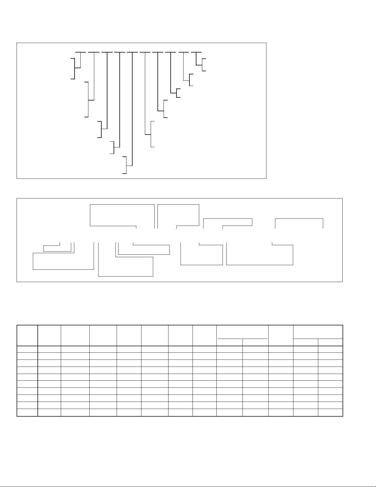
MODEL & SERIAL NUMBER / REPLACEMENT PARTS
Figure 22.1 - Model Number Designations (Remove access cover to locate)
HD 45 A S 01 11 S B A N
HD - Tubular Power Vented
Propeller Unit
HDB - Tubular Power
Vented Blower Unit
30 - 30,000 Btu/hr input
45 - 45,000 Btu/hr input
60 - 60,000 Btu/hr input
75 - 75,000 Btu/hr input
100 - 100,000 Btu/hr input
125 - 125,000 Btu/hr input
MBH Input
Heat Exchanger Type
S - Stainless Steel
A - Aluminized
Ignition Type
S - Direct Spark
01 - 115 volt, 60 hertz,
Power Code
single phase
Dev Digit
Fan Guard Digit
N - None (all blower models)
F - Fingerproof
Control Code
11 - Single Stage, Natural Gas
12 - Two Stage, Natural Gas
21 - Single Stage, Propane Gas
22 - Two Stage, Propane Gas
Factory Installed Option Digit
N - None
Future
A - All
Figure 22.2 - Serial Number Designations (Remove access cover to locate)
SERIAL NUMBER
SPO MODEL
MOTOR SUPPLIER
05 - Universal
15 - Marathon
CONTROL SUPPLIER
01 - RobertShaw
05 - Honeywell
08 - Fenwal
3 0 0 1 1 7 9 9 8 2 3 41 1 100 0 0 0 0 0 0
S
18 - Franklin
38 - A.O. Smith
20 - Morrison
10 - Lau
19 - Air Drive
09 - White Rogers
17 - United Tech
UNIT SERIES
00 - Original 01 - Modified
FAN VENDOR CODE
01 - Revcor
08 - Brookside
GAS VALVE SUPPLIER
01 - RobertShaw
05 - Honeywell
09 - White Rogers
MANUFACTURE
Same as Requirements
Planning Shop Calendar
WEEK OF
YEAR OF MANUFACTURE
SEQUENTIAL NUMBER
Number varies from 0000 to 9999.
Each unit within same week of
manufacture is to have unique number.
SPO NUMBER
Replacement Parts
When requesting parts please contact your local representative. Please have full model and serial number available. If you require
assistance in locating your representative, please call the number located on the back page.
Table 22.1 - Common Replacement Parts (The list is subject to change. Please refer to unit mounted parts list for most up-to-date list.)
Model
Size
Power
Exhauster
Limit
Control
Switch
Flame
Roll-out
Switch
Transformer
Pressure
Switch
Igniter
Ignition
Control
(1 Stage)
Combination Gas
Valve (1 Stage)
Code 11
Code 21
Ignition
Control
(2 Stage)
HD30 5H75038 5H75769-1 5H75002-7 5H75029 5H75030-3 5H79636 5H79749 5H79751 5H79869 NA NA NA
HD45 5H75038 5H75769-1 5H75002-7 5H75029 5H75030-3 5H79636 5H79749 5H79751 5H79869 NA NA NA
HD60 5H75038 5H75769-2 5H75002-7 5H75029 5H75030-3 5H79636 5H79749 5H79751 5H79869 NA NA NA
HDB60 5H75038 5H75769-4 5H75002-7 5H75029 5H75030-3 5H79636 5H79749 5H79751 5H79869 NA NA NA
HD75 5H75038 5H75769-2 5H75002-7 5H75029 5H75030-4 5H79636 5H79749 5H79751 5H79869 5H79804 5H79748 5H79871
HDB75 5H75038 5H75769-2 5H75002-7 5H75029 5H75030-4 5H79636 5H79749 5H79751 5H79869 5H79804 5H79748 5H79871
HD100 5H79795 5H75769-2 5H75002-4 5H75029 5H79441-9 5H79636 5H79749 5H79751 5H79869 5H79804 5H79748 5H79871
HDB100 5H79795 5H75769-3 5H75002-4 5H75029 5H79441-9 5H79636 5H79749 5H79751 5H79869 5H79804 5H79748 5H79871
HD125 5H79795 5H75769-1 5H75002-4 5H75029 5H79441-9 5H79636 5H79749 5H79751 5H79869 5H79804 5H79748 5H79871
HDB125 5H79795 5H75769-2 5H75002-4 5H75029 5H79441-9 5H79636 5H79749 5H79751 5H79869 5H79804 5H79748 5H79871
22
6-583.9
Combination Gas
Valve (2 Stage)
Code 12
Code 22
Page 23

THIS PAGE INTENTIONALLY LEFT BLANK
6-583.9
23
Page 24
COMMERCIAL WARRANTY
Seller warrants its products to be free from defects in material and
workmanship, EXCLUSIVE, HOWEVER, of failures attributable to the use
of materials substituted under emergency conditions for materials normally
employed. This warranty covers replacement of any parts furnished from the
factory of Seller, but does not cover labor of any kind and materials not
furnished by Seller, or any charges for any such labor or materials, whether
such labor, materials or charges thereon are due to replacement of parts,
adjustments, repairs, or any other work done. This warranty does not apply to
any equipment which shall have been repaired or altered outside the factory of
Seller in any way so as, in the judgment of Seller, to affect its stability, nor
which has been subjected to misuse, negligence, or operating conditions in
excess of those for which such equipment was designed. This warranty does
not cover the effects of physical or chemical properties of water or steam or
other liquids or gases used in the equipment.
BUYER AGREES THAT SELLER’S WARRANTY OF ITS PRODUCTS TO BE
FREE FROM DEFECT IN MATERIAL AND WORKMANSHIP, AS LIMITED
HEREIN, SHALL BE IN LIEU OF AND EXCLUSIVE OF ALL OTHER
WARRANTIES, EITHER EXPRESS OR IMPLIED, WHETHER ARISING
FROM LAW, COURSE OF DEALING, USAGE OF TRADE, OR OTHERWISE,
THERE ARE NO OTHER WARRANTIES, INCLUDING WARRANTY OF
MERCHANTABILITY OR FITNESS FOR PURPOSE, WHICH EXTEND
BEYOND THE PRODUCT DESCRIPTION CONFIRMED BY BUYER AND
SELLER AS OF THE DATE OF FINAL AGREEMENT.
This warranty is void if the input to the product exceeds the rated input as
indicated on the product serial plate by more than 5% on gas-fired and oil-fired
units, or if the product in the judgment of SELLER has been installed in a
corrosive atmosphere, or subjected to corrosive fluids or gases, been subjected
to misuse, negligence, accident, excessive thermal shock, excessive humidity,
physical damage, impact, abrasion, unauthorized alterations, or operation
contrary to SELLER’S printed instructions, or if the serial number has been
altered, defaced or removed.
BUYER AGREES THAT IN NO EVENT WILL SELLER BE LIABLE FOR
COSTS OF PROCESSING, LOST PROFITS, INJURY TO GOODWILL, OR
ANY OTHER CONSEQUENTIAL OR INCIDENTAL DAMAGES OF ANY KIND
RESULTING FROM THE ORDER OR USE OF ITS PRODUCT, WHETHER
ARISING FROM BREACH OF WARRANTY, NONCONFORMITY TO
ORDERED SPECIFICATIONS, DELAY IN DELIVERY, OR ANY LOSS
SUSTAINED BY THE BUYER.
BUYER’S REMEDY FOR BREACH OF WARRANTY, EXCLUSIVE OF ALL
OTHER REMEDIES PROVIDED BY LAW, IS LIMITED TO REPAIR OR
REPLACEMENT AT THE FACTORY OF SELLER, ANY COMPONENT WHICH
SHALL, WITHIN THE APPLICABLE WARRANTY PERIOD DEFINED HEREIN
AND UPON PRIOR WRITTEN APPROVAL, BE RETURNED TO SELLER
WITH TRANSPORTATION CHARGES PREPAID AND WHICH THE
EXAMINATION OF SELLER SHALL DISCLOSE TO HAVE BEEN DEFECTIVE;
EXCEPT THAT WHEN THE PRODUCT IS TO BE USED BY BUYER AS A
COMPONENT PART OF EQUIPMENT MANUFACTURED BY BUYER,
BUYER’S REMEDY FOR BREACH, AS LIMITED HEREIN, SHALL BE
LIMITED TO ONE YEAR FROM DATE OF SHIPMENT FROM SELLER. FOR
GAS-FIRED PRODUCTS INSTALLED IN HIGH HUMIDITY APPLICATIONS
AND UTILIZING STAINLESS STEEL HEAT EXCHANGERS, BUYER’S
REMEDY FOR BREACH, AS LIMITED HEREIN, SHALL BE LIMITED TO
TEN YEARS FROM DATE OF SHIPMENT FROM SELLER.
These warranties are issued only to the original owner-user and cannot be
transferred or assigned. No provision is made in these warranties for any
labor allowance or field labor participation. Seller will not honor any expenses
incurred in its behalf with regard to repairs to any of Seller’s products. No
credit shall be issued for any defective part returned without proper written
authorization (including, but not limited to, model number, serial number,
date of failure, etc.) and freight prepaid.
OPTIONAL SUPPLEMENTAL WARRANTY
Provided a supplemental warranty has been purchased, Seller extends the
warranty herein for an additional four (4) years on certain compressors.
Provided a supplemental warranty has been purchased, Seller extends the
warranty herein for an additional four (4) years or nine (9) years on certain
heat exchangers.
EXCLUSION OF CONSUMABLES & CONDITIONS BEYOND SELLER’S
CONTROL
This warranty shall not be applicable to any of the following items: refrigerant
gas, belts, filters, fuses and other items consumed or worn out by normal wear
and tear or conditions beyond Seller’s control, including (without limitation as
to generality) polluted or contaminated or foreign matter contained in the air or
water utilized for heat exchanger (condenser) cooling or if the failure of the part
is caused by improper air or water supply, or improper or incorrect sizing of
power supply.
Component
Applicable Models
Heat Exchangers
Gas-Fired Units
Heat Exchangers
Low Intensity Infrared Units
Compressors
Condensing Units for Cassettes
Burners
Low Intensity Infrared Units
Other
Components excluding Heat Exchangers,
Coils, Condensers, Burners, Sheet Metal
Heat Exchangers/Coils
Indoor and Outdoor Duct Furnaces and
System Units, Steam/Hot Water Units, Oil-Fired
Units, Electric Units, Cassettes, Vertical Unit
Ventilators, Ventilators, Geothermal Units
Compressors
Vertical Unit Ventilators, Ventilators, Geothermal Units
Burners
High Intensity Infrared Units
Sheet Metal Parts
All Products
TEN YEARS FROM DATE OF FIRST BENEFICIAL USE BY BUYER OR ANY OTHER USER, WITHIN
TEN YEARS FROM DATE OF RESALE BY BUYER OR ANY OTHER USER, WITHIN TEN YEARS
FROM DATE OF RESALE BY BUYER IN ANY UNCHANGED CONDITION, OR WITHIN ONE
HUNDRED TWENTY-SIX MONTHS FROM DATE OF SHIPMENT FROM SELLER, WHICHEVER
OCCURS FIRST
FIVE YEARS FROM DATE OF FIRST BENEFICIAL USE BY BUYER OR ANY OTHER USER, WITHIN
FIVE YEARS FROM DATE OF RESALE BY BUYER OR ANY OTHER USER, WITHIN FIVE YEARS
FROM DATE OF RESALE BY BUYER IN ANY UNCHANGED CONDITION, OR WITHIN SIXTY-SIX
MONTHS FROM DATE OF SHIPMENT FROM SELLER, WHICHEVER OCCURS FIRST
TWO YEARS FROM DATE OF FIRST BENEFICIAL USE BY BUYER OR ANY OTHER USER, WITHIN
TWO YEARS FROM DATE OF RESALE BY BUYER IN ANY UNCHANGED CONDITION, OR WITHIN
THIRTY MONTHS FROM DATE OF SHIPMENT FROM SELLER, WHICHEVER OCCURS FIRST
ONE YEAR FROM DATE OF FIRST BENEFICIAL USE BY BUYER OR ANY OTHER USER, WITHIN
ONE YEAR FROM DATE OF RESALE BY BUYER IN ANY UNCHANGED CONDITION, OR WITHIN
EIGHTEEN MONTHS FROM DATE OF SHIPMENT FROM SELLER, WHICHEVER OCCURS FIRST
“APPLICABLE WARRANTY PERIOD”
As Modine Manufacturing Company has a continuous product improvement program, it reserves the right to change design and specifications without notice.
© Modine Manufacturing Company 2014
Modine Manufacturing Company
1500 DeKoven Avenue
Racine, WI 53403
Phone: 1.800.828.4328 (HEAT)
www.modinehvac.com
 Loading...