


查询TSX07301022供应商
Modicon TSX Nano PLCs
Characteristics :
pages 40050/9 to 40050/11
References :
pages 40050/12 to 40050/14
Dimensions :
page 40050/15
Connections :
pages 40050/16 to 40050/19
Nano PLCs
Presentation
New features on Nano PLCs
The range of Nano PLCs includes new functions with :
i Non-extendable Nano PLC bases for small configurations.
i Nano PLC extensions which can be used to augment extendable Nano PLC bases at minimum cost.
i Analogue I/O extension modules (with c 100…240 V or a 24 V power supply) incorporating 3 inputs and 1 output.
Presentation
Nano PLCs are very compact and offer a cost-effective replacement for traditional solutions while increasing application
flexibility and ease of wiring.
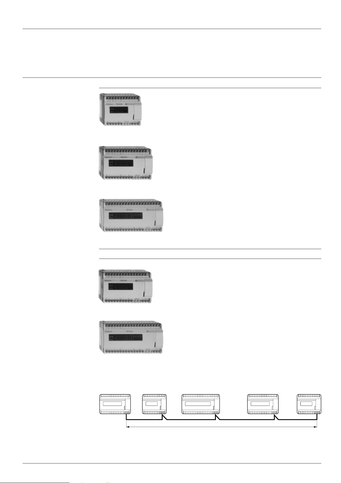
Nano PLCs are available in 3 formats :
i Nano PLC bases with 10, 14, 16, 20 or 24 non-extendable I/O.
i Nano PLC bases with 10, 16 or 24 extendable I/O, which can be augmented with an I/O extension and up to 3 PLC
extensions.
i Nano PLC extensions with 16 or 24 I/O which can be used to augment extendable Nano PLC bases (1 extension per
base).
Non-extendable Nano PLC bases
Non-extendable Nano PLC bases will not accept any
extension. They all have a c 100…240 V power supply,
depending on the model :
i 10 I/O : 6 inputs + 4 outputs and 1 analogue input.
i 14 I/O : 8 inputs + 6 outputs.
i 16 I/O : 9 inputs + 7 outputs and 1 analogue input.
i 20 I/O : 12 inputs + 8 outputs.
Nano PLCs with 10 I/O
Nano PLCs with 14/16 I/O
i 24 I/O : 14 inputs + 10 outputs and 1 analogue input.
The following types of inputs and outputs are used :
i Inputs : a 24 V (sensor supply is not protected).
i Outputs : relay.
These PLCs incorporate extended communication : UniTelway master/slave link or ASCII link for transmission/
reception.
Models with 10, 14 and 20 I/O do not have a real-time clock.
40050/2
Nano PLCs with 20/24 I/O

Modicon TSX Nano PLCs
Characteristics :
pages 40050/9 to 40050/11
References :
pages 40050/12 to 40050/14
Dimensions :
page 40050/15
Connections :
pages 40050/16 to 40050/19
Nano PLCs
Description
Description
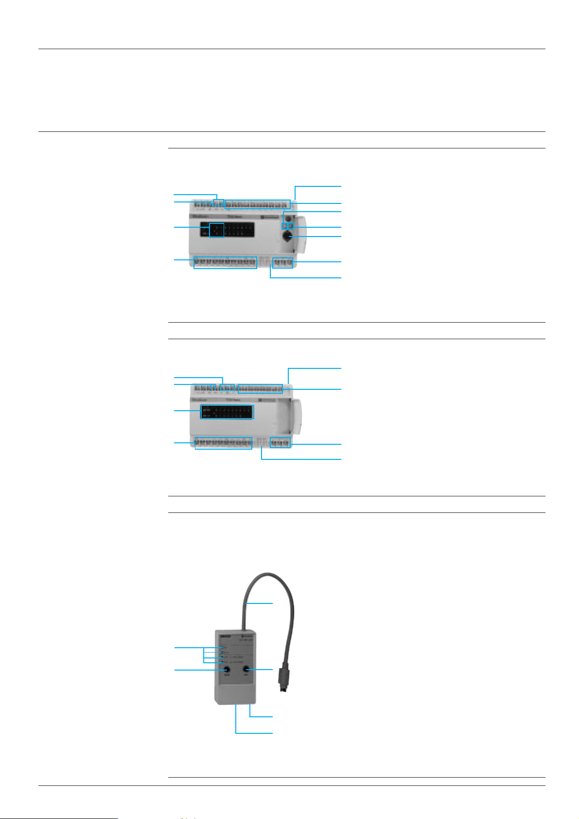
Non-extendable Nano PLCs
The front panels of TSX 07 3L ii28 non-extendable Nano PLCs comprise :
7
4
3
2
6
1 A port (1) for connecting a programming terminal (or
Uni-Telway bus or serial link)
2 A display of :
5
- inputs 0 to 7 or 0 to 11
- outputs 0 to 5 or 0 to 7
8
- PLC status (RUN, ERR, COM, I/O)
1
3 A mains power supply connection
4 A sensor power supply (a 24 V/150 mA)
5 An input sensor connection
6 An output preactuator connection
7 A removable cover for protecting the screw terminal
7
blocks
8 A potentiometer
Extendable Nano PLCs
The front panels of TSX 07 30 10ii extendable Nano PLCs with 10 I/O comprise :
1 A port (1) for connecting a programming terminal (or
6
5
4
8
The front panels of TSX 07 31 16/24ii extendable Nano PLCs with 16/24 I/O comprise :
6
5
4
8
10
7
2
3
1
9
10
Uni-Telway bus or serial link)
2 A selector switch for coding the base/extension function
3 A potentiometer
4 A display of :
- inputs 0 to 5 and outputs 0 to 3
- PLC status (RUN, ERR, COM, I/O)
5 A mains power supply connection
6 A sensor power supply (a 24 V/150 mA) on models
with a c 100…240 V supply
7 An input sensor connection
8 An output preactuator connection
9 An extension connection (I/O extension and/or PLC
extension) or Modbus slave connection
10 A removable cover for protecting the screw terminal
blocks
10
1 A port (1) for connecting a programming terminal (or
Uni-Telway bus or serial link)
7
2 A selector switch for coding the base/extension function
3 Two potentiometers
4 A display of :
2
3
- inputs 0 to 8 or 0 to 13 and outputs 0 to 6 or 0 to 9
1
- PLC status (RUN, ERR, COM, I/O)
5 A mains power supply connection
6 A sensor power supply (a 24 V/150 mA) on models
9
with a c 100...240 V supply
7 An input sensor connection
10
8 An output preactuator connection
9 An extension connection (I/O extension and/or PLC
extension) or Modbus slave connection
10 A removable cover for protecting the screw terminal
blocks
40050/4
(1) Female 8-way mini-DIN type connector.
Modicon TSX Nano PLCs
Characteristics :
pages 40050/9 to 40050/11
References :
pages 40050/12 to 40050/14
Dimensions :
page 40050/15
Connections :
pages 40050/16 to 40050/19
Nano PLCs
Presentation
Extendable Nano PLC bases
Nano PLCs with 10 I/O
Nano PLCs with 16 I/O
(continued)
Nano PLCs, with a 24 V or c 100...240 V power supply,
are available with three different I/O combinations :
i 10 I/O : 6 inputs + 4 outputs.
i 16 I/O : 9 inputs + 7 outputs.
i 24 I/O : 14 inputs + 10 outputs.
There are many types of I/O :
i Inputs : a 24 V, c 115 V, analogue 0/10 V.
i Outputs : relay outputs, transistor outputs a 24 V/0.5 A
(positive logic : load common at “-”), transistor outputs
a 24 V/0.5 A (negative logic : load common at “+”).
Nano PLCs are programmed in lists of instructions using
the FTX 117 programming terminal, in Ladder or Instruction list language using software on an FT 2000, FTX 517
terminal or PC compatible. Instruction list and Ladder
programs are reversible on FTX terminals or PC compatibles.
Nano PLCs are easy to set up and have numerous built-in
functions (EEPROM memory for storing programs, batterybacked RAM, real-time clocks for models with 16 and 24
I/O). They can be installed easily on a mounting rail or base
plate, in a vertical or horizontal position.
Nano PLCs with 24 I/O
Nano PLCs with 16 I/O (c inputs)
Nano PLC extensions
Nano PLC extensions can be used to augment extendable
Nano PLCs using a single extension per base.
They all have a c 100…240 V or a 24 V power supply
and, depending on the model :
i 16 I/O : 9 inputs + 7 outputs.
i 24 I/O : 14 inputs + 10 outputs.
Nano PLC extensions with 16 I/O
The following types of inputs and outputs are used :
i Inputs : a 24 V.
i Outputs : relay outputs for models with c 100…240 V
power supply, transistor outputs with positive logic for
models with a 24 V power supply.
Nano PLC extensions with 24 I/O
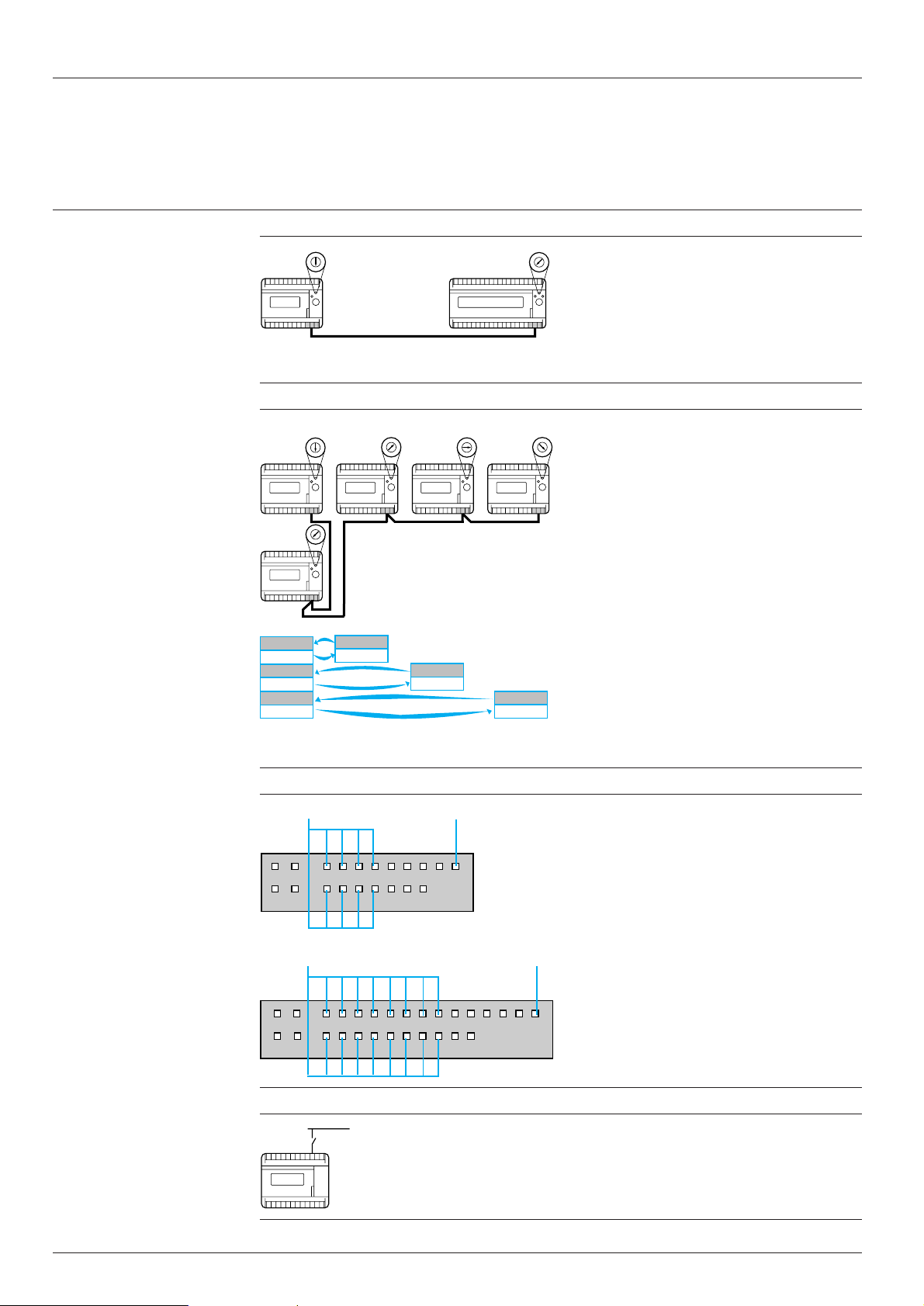
Each extendable Nano base PLC 1 can be augmented using an I/O extension 2, made up of one of the extendable Nano
PLCs or a Nano extension.
In addition, up to three PLC extensions 3, 4 and 5 communicating via exchange words can be connected to the base PLC.
Only the base PLC can receive an I/O extension.
I/O extensionBase PLC PLC extension PLC extension PLC extension
123 45
200 m maximum
This extension link can be used exclusively as a Modbus slave link.
40050/3
Modicon TSX Nano PLCs
Characteristics :
pages 40050/9 to 40050/11
References :
pages 40050/12 to 40050/14
Dimensions :
page 40050/15
Connections :
pages 40050/16 to 40050/19
Nano PLCs
Description
Nano PLCs (with integrated analogue input)
The front panels of TSX 07 32/33 ii28 Nano PLCs with 10/16/24 I/O and 1 integrated analogue input comprise :
6
5
4
8
Nano PLC extensions
(continued)
1 A port (1) for connecting a programming terminal (or
10
7
2
3
1
9
10
Uni-Telway bus or ASCII link)
2 A point for adjusting the analogue input error
3 A potentiometer (for TSX Nano with 16/24 I/O)
4 A display of :
- discrete relay outputs and inputs
- PLC status (RUN, ERR, COM, I/O)
5 A mains power supply connection c 100…240 V
6 A sensor power supply a 24 V/150 mA
7 An input sensor connection
8 An output preactuator connection
9 An analogue input connection 0-10 V
10 A removable cover for protecting the screw terminal
blocks
The front panels of TSX 07 EX iiii Nano PLC extensions comprise :
1 A display of :
3
2
1
5
Program loader
The TSX PGR LDR module is designed to simplify duplicating or updating applications on Nano and Micro PLCs without
the need for a programming terminal. An application (in internal RAM) can be transferred from a PLC to the TSX PGR LDR
module (and saved within it), then transferred from the TSX PGR LDR module to a PLC.
1
2
7
4
6
7
- inputs 0 to 8 or 0 to 13
- outputs 0 to 6 or 0 to 9
- PLC status (RUN, ERR, COM, I/O)
2 A mains power supply connection
3 A sensor power supply (a 24 V/150 mA) on models
with a c 100...240 V supply
4 An input sensor connection
5 An output preactuator connection
6 A connection to the Nano base PLC
7 A removable cover for protecting the screw terminal
blocks
The front panel of the TSX PGR LDR module comprises :
1 A cord for connecting to the PLC programming port
2 Four operation indicator lights
3 A W/R button which selects the program transfer direction
(PLC v module or module v PLC).
4 A GO button to start the transfer
5 A Write Only switch which prevents PLC v module
transfer
6 A Program Protect switch which protects the PLC appli-
cation as read-only after the transfer
3
(1) Female 8-way mini-DIN type connector.
4
5
6
40050/5
Modicon TSX Nano PLCs
Characteristics :
pages 40050/9 to 40050/11
References :
pages 40050/12 to 40050/14
Dimensions :
page 40050/15
Connections :
pages 40050/16 to 40050/19
Nano PLCs
Functions
I/O extension (1)
Base
PLC
Peer PLCs (1)
Base
PLC
I/O
extension
345
6
2
1
7
0
PLC 2
345
6
2
1
7
0
345
6
2
1
7
0
Extension link
345
6
2
1
7
0
Peer PLC & extension link
PLC 3
I/O
extension
345
6
2
1
7
0
PLC 4
345
Each Nano base PLC can be extended using an I/O
6
2
1
7
0
extension. This extension is created by one of the PLCs
with 10, 16 or 24 I/O. The function of each PLC is defined
by the position of the coding selector switch :
i Position 0 : base PLC
i Position 1 : I/O extension
The extension link cable between the base PLC and the
I/O extension is a shielded, twisted pair and is no more than
200 metres long.
Up to 3 peer PLCs, communicating via common words, can
345
be connected to the base PLC. In this case, only the base
6
2
1
7
0
PLC can receive an I/O extension. The function of each
PLC is defined by the position of the coding selector switch.
I/O addressing of peer PLCs is identical to that of the base
PLC.
The extension link cable between the base PLC and PLC
extensions is a shielded, twisted pair and is no more than
200 metres long.
Base
PLC
IW
QW
IW
QW
IW
QW
PLC 2
QW
IW
PLC 3
QW
IW
QW
IW
PLC 4
Displaying the I/O, internal bits and PLC status
State of 8 internal bits if %S69 = 1
RUN
COM
State of 16 internal bits if %S69 = 1
RUN
COM
I
ERR
012345678
O
I/O
0123456
Nano PLCs with 10 and 16 I/O
I
ERR
012345678910111213
O
I/O
0123456789
System bit % S69
System bit % S69
Nano PLCs with 24 I/O
Inter-PLC communication
Each PLC has 2 reserved (IW) and 2 reserved (QW) words
for exchanging data between PLCs. These exchange words
are updated automatically. For each PLC, the user program
is only able to :
i Write to the 2 %QW output words
i Read the 2 %IW input words
The results of the self-tests performed continuously by the
base PLC, peer PLCs and I/O extensions are displayed on
the front panel by 4 indicator lamps :
i RUN : PLC status
i ERR : internal fault
i COM : data exchange on the extension link
i I/O : I/O fault
I/O display
The state of each I/O is displayed on the front panel of the
PLC by an indicator lamp : when the lamp is on, the I/O is
active, when the lamp is off, the I/O is inactive.
Internal bits display
When the PLC system bit %S69 is set to 1, the first
indicator lamps show the state of 8 or 16 defined internal
bits (%M120…%M127 or %M112…%M127).
40050/6
Dedicated I/O
Base PLC
RUN/STOP
123450C
The RUN/STOP input will launch or stop program execution
from an external order. After configuration, one of the first
6 inputs (%I0.0 to %I0.5) can be assigned to this function.
One of the first 4 outputs (%Q0.0 to %Q0.3) can be
configured to indicate to the user that the PLC program is
120C
not running (STOP or fault).
(1) TSX 07 30/31 PLCs can no longer receive an I/O extension or peer PLC when the integrated Modbus link is in use.
TSX 07 32/33 ii28 and TSX 07 3L ii28 PLCs cannot take an I/O extension or peer PLC.
Modicon TSX Nano PLCs
Characteristics :
pages 40050/9 to 40050/11
References :
pages 40050/12 to 40050/14
Dimensions :
page 40050/15
Connections :
pages 40050/16 to 40050/19
Nano PLCs
Functions
Real-time based programming
Nano PLC
Analogue I/O
TSX 073i ii12
(continued)
ASN
AEN
Nano PLCs with 16 or 24 I/O integrate 16 user-definable
real-time clocks which can be used to :
i Control the outputs directly (opening and closing electrical
circuits) or act on the user program according to the time
(month, day, hour and minute).
i Program time setpoints which can be modified via an
operator panel or calculated by the program.
i Program event time-stamping or perform time
calculations.
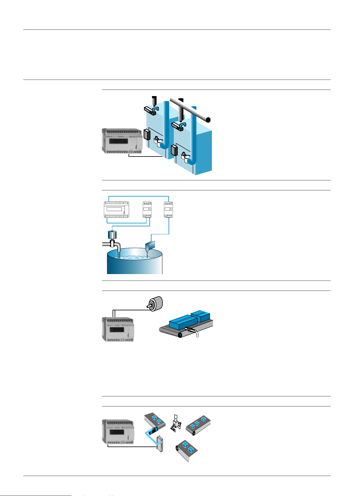
The Nano PLC is designed for simple process control
applications (level, temperature, flow rate control, etc) with
speed controller or servo-valve control.
TSX AEN/ASN modules are used with Nano PLCs to
process 1 analogue input and 1 analogue output respectively :
i The input module, 0/10 V - 10/+ 10 V or 4/20 mA is
connected to the a 24 V input %I0.0 of the PLC and is
configured in frequency meter mode.
i The output module, 0/10 V - 10/+ 10 V or 4/20 mA uses
the pulse width modulation transistor output %Q0.0.
Analogue processing is also possible using three
TSX 07 32/33 ii28 bases which consist of 1 analogue
input 0-10 V.
High-speed processing applications
Nano PLC
Pulse outputs
Nano PLC
On a base PLC or peer PLC, each of the first 6 inputs (%I0.0
to %I0.5) can be assigned to the latching function after
configuration. This function is used to take account of input
pulses with short durations, 100 µs minimum.
Nano PLCs include standard functions which are easy to
set up and can be used for adaptation to control systems
requiring counting capacity or short response times :
i Fast counter (maximum frequency 10 kHz)
i Fast up/down counter (maximum frequency 1 kHz)
i Frequency meter (maximum frequency 10 kHz)
Sensors which are used on the up/down counter inputs
(%I0.0 and %I0.3) must have solid state outputs.
2 reflex outputs (%Q0.1 and %Q0.2) are controlled directly
by the fast counter (without waiting for outputs to be
updated at the end of the scan) according to a matrix
predefined during configuration.
After configuration, the first output %Q0.0 (if it is a transistor
output) of the Nano PLC can be used with :
i The PWM software function, as a pulse width modulation
output at a predefined frequency of up to 4.9 kHz
designed for use in applications with light or sound
intensity control (dimmer function).
i The PULSE software function, as a pulse generator
output of up to 4.9 kHz designed for use for controlling
stepper motors.
40050/7

Modicon TSX Nano PLCs
Characteristics :
pages 40050/9 to 40050/11
References :
pages 40050/12 to 40050/14
Dimensions :
page 40050/15
Connections :
pages 40050/16 to 40050/19
Nano PLCs
Functions
Uni-Telway communication
Modbus slave communication
(continued)
Micro
Nano
The Nano PLC can communicate with other Uni-Telway
devices via the terminal port : speed controllers, operator
terminals, compact or modular PLCs.
The ability to send and receive messages means that Nano
PLCs can be integrated in distributed architectures.
In slave mode, for example, the Nano PLC can initiate
communication and send updated variables to the bus
master (local reflex processing).
28 Nano slave PLCs can be connected to the Uni-Telway
bus over a distance of 1 km (isolated for speeds of 1.2 to 9.6
K bits/s).
CCX 17
Nano PLCs have an RS 485 serial link extension port,
supporting the Modbus protocol (depending on the model).
It is used to perform the following requests :
ASCII communication
Bar
code
reader
Modem application (Modbus or Uni-Telway protocol)
Micro
Nano
i Read/write bits and words
i Read PLC status (via Uni-TE request)
i Set to RUN or STOP mode (via Uni-TE request)
i Initialise the PLC (via Uni-TE request)
Up to 28 Nano PLCs can be connected over a distance of
200 m for user-definable speeds of 1.2 to 19.2 K bits/s.
The ability to send and receive characters enables the
Nano PLC to communicate in point-to-point mode with a
large number of ASCII devices, such as PCs (directly or via
modem), printers, bar code readers, etc.
Frame speed and format can be configured. Connection to
the Nano PLC terminal port is via an RS 232/485 converter
cable powered by the PLC.
A PLC fitted with a Modbus or Uni-Telway master module
interrogates Nano PLCs via the switched telephone network.
When connected to a Modem in RS 485 mode, the master
can use the link to generate dialling sequences for remote
sites.
Each Nano PLC responds to requests from the master, but
is also able to trigger a call by activation of a discrete input
on the Modem.
40050/8
Nano
Nano
Target applications (with Modbus or Uni-Telway) :
i System teleprocessing
i Telemonitoring of remote sites
i Water, energy, environment control
The Uni-Telway slave link of Nano PLCs can also be used
for :
i Up/down loading programs
i Programming and remote diagnostics

Modicon TSX Nano PLCs
Nano PLCs
References :
pages 40050/12 to 40050/14
Dimensions :
page 40050/15
Connections :
pages 40050/16 to 40050/19
Environment
Conforming to standards IEC 1131-2, IEC 664, UL 508, UL 746 C, UL 94, CSA 22-2 no. 142, EN 50081/class B
Characteristics
Temperature Operation
Storage
Humidity Without condensation % 5…95
Altitude m 0…2000
Vibration resistance Conforming to IEC 68-2-6 FC tests
Mechanical shock resistance Conforming to IEC 68-2-27 EA tests
°
C 0…+ 60
°
C - 25…+ 70
Power supply characteristics
Type of PLC TSX 07 30/31/32/33 iii8, TSX 07 3L ii28, TSX 07 30/31 iii2, TSX 07 EX ii12
Supply Nominal V c 100…240 a 24
voltage
Limit V 85…264 19.2…30
Frequency Nominal Hz 50/60 –
Limit Hz 47…63 –
Power required ≤ 30 VA ≤ 14 W
Sensor protected power supply V 24/150 mA –
Primary/earth isolation Vrms 2000/50-60 Hz 2000/50-60 Hz
Microbreaks Duration ms ≤ 10 ≤ 1
TSX 07 EX ii28
Discrete input characteristics
Type of input V
Nominal Voltage V a 24 c 110/120
input
values Current mA 710
Sensor supply V a 19.2…30 (including ripple) –
Limit input At state 1 Voltage V ≥ 11 ≥ 79
values
Current mA ≥ 2.5 for 11 V ≥ 4 for 79 V
At state 0 Voltage V ≤ 5 ≤ 20
Current mA ≤ 1.2 ≤ 2
Logic Positive or negative depending on wiring –
Filter time 12 ms, 3 ms or 100 µs (on I0.0 to I0.7)/375 µs 12 ms
Isolation Betw. grps of I/O points Vrms 1500/50-60 Hz 1500/50-60 Hz
Type Optoelectronic module –
aa
a 24 (resistive)
aa
(on I0.8 to I0.13)
cc
c 115 (capacitive)
cc
40050/9

Modicon TSX Nano PLCs
Nano PLCs
References :
pages 40050/12 to 40050/14
Dimensions :
page 40050/15
Connections :
pages 40050/16 to 40050/19
Characteristics
Discrete output characteristics
Type of output Relay Transistor, positive logic Transistor, negative logic
Output description 1 normally open contact Protected Non-protected
Loads Voltage V c 24…220 a 24 a 24
(nominal
values) Nominal current A – 0.5 0.5
Tungsten lamp W – ≤ 10 ≤ 10
aa
a loads Voltage V 24 19.2…30 19.2…30
aa
Current A DC-12 : 1-24 V (0.3 x 10
c c
c loads AC-12 resistive A 1-110/220 V (0.5 x 10⁶ op. cycles) – –
c c
duty 0.5-110/220 V (2 x 10⁶ op. cycles)
DC-13 : 0.4-24 V (1 x 10⁶ op. cycles) common to “-” loads common to “+” loads
1-48 V (0.5 x 10⁶ op. cycles)
2-24 V (0.3 x 10⁶ op. cycles)
1-24 V (0.5 x 10⁶ op. cycles)
(continued)
6
op. cycles) 0.625 (at 30 V) 0.625 (at 30 V)
AC-15 inductive A 0.22-220 V (1 x 10⁶ op. cycles) – –
duty 0.5-24/48/110 V (1 x 10⁶ op. cycles)
Response State 0 to 1 ms ≤ 5 ≤ 1 ≤ 1
time
State 1 to 0 ms ≤ 10 ≤ 1 ≤ 1
Leakage
current At state 0 mA – ≤ 1 ≤ 1
Voltage
drop At state 1 V – ≤ 2 (for I = 0.5 A) ≤ 1.5 (for I = 0.5 A)
Built-in Overloads None (fit one fuse per I/O point or Yes None (fit a fuse on the preactuator
protection and short-circuits group of I/O points) common)
Overvoltages None (fit RC or GMOV peak limiter circ. Yes Yes
Polarity
inversions – Yes Yes
1-24 V (0.2 x 10⁶ op. cycles)
for c and a freewheel diode for a )
Integrated analogue input characteristics
Type of PLC TSX 07 32/33 ii28
Analogue Number of points 1
input
Input range V 0…10
Input impedance k
Max. voltage V ± 16
without destruction
Type of protection Against short-circuits
Ω
16…18
Conversion Method Successive approximations
Isolation Analogue input V None
Wiring Isolated sensor m 30 max.
distance with
shielded cable Non-isolated sensor m 10 max.
40050/10
Resolution 8 bits
Conversion time PLC scan time
Precision at 25 °C % FS ± 0.8
at 60 °C % FS ± 2
Drift 0.34 % per 10 °C
Repeatability V ± 0.8 % of 0 to 60 °C (at full scale)
and processor

Modicon TSX Nano PLCs
Nano PLCs
References :
pages 40050/12 to 40050/14
Dimensions :
page 40050/15
Connections :
pages 40050/16 to 40050/19
Modbus characteristics
Type of PLC TSX 07 30/31 iiii
Characteristics
(continued)
Structure Description Heterogeneous industrial bus
Transmission Mode Asynchronous in base band, RTU/ASCII frame
Configuration Number of devices 28 devices maximum, 98 link addresses maximum
Available Modbus/Jbus slave Code Description Code Description
functions 01 Reading of n consecutive output bits 05 Writing of 1 output bit
Services Sending requests Bits : 120 bits maximum per request
Physical interface RS 485 non-isolated
Method of access Master/slave type
Bit rate 1.2 K bits/s to 19.2 K bits/s
Medium Double shielded twisted pair
Bus length 200 m maximum
Drop cable 15 m maximum
02 Reading of n consecutive input bits 06 Writing of 1 output word
03 Reading of n consecutive output words 15 Writing of n output bits
04 Reading of n consecutive input words 16 Writing of n output words
Words : 120 words maximum per request
Safety One CRC 16 check parameter on each frame
Monitoring Diagnostics counters, event counters
ASCII asynchronous serial link characteristics
Type of PLC TSX 07 30/31/32/33 iiii, TSX 07 3L iiii
Physical layer Terminal port RS 485 non-isolated Half-duplex (10 m max)
Flow rate 1.2 K bits/s to 9.6 K bits/s
Transmission Type Point-to-point, without flux control (Xon-Xoff, RTS/CTS)
Services 120 character messages Transmission/reception
Uni-Telway integrated link characteristics
Type of PLC TSX 07 30/31/32/33 iiii, TSX 07 3L iiii
Structure Physical interface RS 485 terminal port Half-duplex non-isolated
Configuration Number of devices Master : 3 devices maximum (5 link addresses maximum)
Services Uni-TE server Writing or reading Nano master data after a request is sent by a connected
Data 7 or 8 bits
Stop bit 1 or 2 bits
Parity bit Even, odd or no parity
(general characteristics, see page 43594/2)
Bit rate 1.2 to 9.6 K bits/s
Functions Master/slave
Slave : 28 devices maximum
(96 link addresses max.)
Bus length 10 m max, 1000 m when using the TSX P ACC 01 terminal port cable connector
client device
Reception of messages from all
devices on the bus (master or slave)
128 bytes maximum
Uni-TE client Sending requests (128 bytes maximum) to :
(master function) - all slave devices on the bus
Uni-TE client Sending messages to every device on
(slave function) the bus (master or slave), 128 bytes
maximum
40050/11

Characteristics :
pages 40050/9 to 40050/11
Dimensions :
page 40050/15
Connections :
pages 40050/16 to 40050/19
TSX 07 3L 1428
Modicon TSX Nano PLCs
Nano PLCs
References
Non-extendable Nano PLC bases
These bases will not accept any extension. They incorporate extended communication : Uni-Telway master/slave link or
ASCII link for transmission/reception.
a 24 V/150 mA sensor power supply is not protected.
Number Inputs Relay Transistor outputs Reference Weight
of I/O outputs 24 V/0.5 A (1) kg
cc
c 100…240 V power supply
cc
14 8 a 24 V 6 – TSX 07 3L 1428 0.320
20 12 a 24 V 8 – TSX 07 3L 2028 0.340
TSX 07 3L 2028
ii
TSX 07
i 010ii
ii
ii
TSX 07
i1 16ii
ii
Extendable Nano PLC bases
These Nano PLC bases are used as base PLCs (1 per configuration), as I/O extensions (maximum 1 per configuration)
or as peer PLCs (maximum 3 per configuration). They integrate an extended communication function : Uni-Telway master/
slave link or ASCII link in transmission/reception and Modbus slave link.
Number Inputs Relay Transistor outputs Reference Weight
of I/O outputs 24 V/0.5 A (1) kg
aa
a 24 V power supply
aa
10 6 a 24 V 4 – TSX 07 30 1022 0.290
– 4 protected, TSX 07 30 1012 0.270
16 9 a 24 V 7 – TSX 07 31 1622 0.350
– 7 protected, TSX 07 31 1612 0.325
positive logic
4 unprotected, TSX 07 30 1002 0.270
negative logic
positive logic
ii
TSX 07
i1 24ii
ii
40050/12
7 unprotected, TSX 07 31 1602 0.325
negative logic
24 14 a 24 V 10 – TSX 07 31 2422 0.400
– 10 protected, TSX 07 31 2412 0.370
positive logic
10 unprotected, TSX 07 31 2402 0.370
negative logic
(1) Multilingual quick reference guide included as standard (English, French, German, Italian and Spanish).

Characteristics :
pages 40050/9 to 40050/11
Dimensions :
page 40050/15
Connections :
pages 40050/16 to 40050/19
Modicon TSX Nano PLCs
Nano PLCs
References
(continued)
ii
TSX 07
i1 16ii
ii
ii
TSX 07
i1 24ii /TSX 07 21 1648
ii
Extendable Nano PLC bases
Number Inputs Relay Transistor outputs Reference Weight
of I/O outputs 24 V/0.5 A (1) kg
cc
c 100…240 V power supply
cc
10 6 a 24 V 4 – TSX 07 30 1028 0.300
16 9 c 115 V 7 – TSX 07 31 1648 0.390
9 a 24 V 7 – TSX 07 31 1628 0.360
24 14 a 24 V 10 – TSX 07 31 2428 0.410
Nano PLC bases
cc
c 100…240 V power supply
cc
Number Inputs Relay Integrated Reference Weight
of I/O outputs analogue input (1) kg
(with an integrated analogue input) (2)
(continued)
– 4 unprotected, TSX 07 30 1008 0.280
negative logic
– 7 unprotected, TSX 07 31 1608 0.335
negative logic
– 10 unprotected, TSX 07 31 2408 0.380
negative logic
TSX 07 33 1628
TSX 07 EX 16ii
TSX 07 EX 24ii
10 6 a 24 V 4 1 x 0…10 V TSX 07 32 1028 0.290
16 9 a 24 V 7 1 x 0…10 V TSX 07 33 1628 0.290
24 14 a 24 V 10 1 x 0…10 V TSX 07 33 2428 0.290
Nano PLC extensions
These extensions can be used to augment extendable Nano PLC bases at minimum cost (maximum 1 extension per base).
Number Inputs Relay Transistor outputs Reference Weight
of I/O outputs 24 V/0.5 A (1) kg
aa
a 24 V power supply
aa
16 9 a 24 V – 7 protected, TSX 07 EX 1612 0.325
24 14 a 24 V – 10 protected, TSX 07 EX 2412 0.370
cc
c 100…240 V power supply
cc
16 9 a 24 V 7 – TSX 07 EX 1628 0.360
24 14 a 24 V 10 – TSX 07 EX 2428 0.410
positive logic
positive logic
(1) Multilingual quick reference guide included as standard (English, French, German, Italian and Spanish).
(2) TSX 07 32/33 ii28 PLCs do not have I/O extension and/or PLC extension links or the Modbus slave link.
40050/13

Characteristics :
pages 40050/9 to 40050/11
Dimensions :
page 40050/15
Connections :
pages 40050/16 to 40050/19
TSX PRG LDR
Modicon TSX Nano PLCs
Nano PLCs
References
Separate parts
Description Use with Length Reference Weight
Program Simplifies duplicating or 0.3 m TSX PRG LDR 0.150
loader updating applications
with programming (program and constants
port in internal RAM)
connecting cable
Input Nano PLC with 10 I/O – TSX 07 SIM 06 0.050
simulator
a 24/c 115 V
(continued)
kg
Nano PLC with 16 I/O – TSX 07 SIM 09 0.070
TSX P ACC 01
Nano PLC with 24 I/O – TSX 07 SIM 14 0.080
Connecting cables I/O extension 0.3 m TSX CA0 003 0.015
between
Nano PLC bases
PLC extension 50 m TSX STC 050 1.710
200 m TSX STC 200 6.790
Connecting cable Nano PLC terminal port 2,5 m TSX PCX 1130 0.240
for Modem connection to the Modem
(DCE) device (with 25-way male
SUB-D connector)
Terminal port Isolation of Uni-Telway signals 1 m TSX P ACC 01 0.690
cable for distances > 10 m
connector and < 1 km, line termination,
bus drop cable
40050/14
Description Composition Reference Weight
kg
Self-instruction 1 Nano PLC (16 I/O), TSX SDC 07 30 117 0.950
cases (1) 1 input simulator and 1 FTX 117
1 Nano PLC (16 I/O), TSX SDC 07 30 DSF 0.600
1 input simulator
and software under DOS for FT 2000/FTX 517
1 Nano PLC (16 I/O), TSX SDC 07 30 DSP 0.600
1 input simulator
and software under DOS for PC compatible
(1) Multilingual quick reference guide included as standard (English, French, German, Italian and Spanish).

Characteristics :
pages 40050/9 to 40050/11
References :
pages 40050/12 to 40050/14
Connections :
pages 40050/16 to 40050/19
Modicon TSX Nano PLCs
Nano PLCs
Dimensions, mounting
Dimensions
Mounting
85
a60
TSX 07 3i 10ii 105 86
TSX 07 3i 16ii, TSX 07 3L 1428 135 116
TSX 07 3i 24ii, TSX 07 31 1648, TSX 07 3L 2028 165 146
(1) 2 knock-outs Ø 4
G
a G
77
(1)
Mounting
By clicking onto 35 mm
Mounting Removal
Mounting positions on vertical plane
Possible mounting positions Incorrect mounting position
""
" DIN rail, or by screwing onto panel using Ø M3 screws
""
1 1
Installation rules
2
2
1
2
a
2
1
1 End stop AB1-AB8P35
2 Access cover
b
a
1 Switchgear, enclosure or machine frame
2 Cable ducting or clips
a ≥ 20 mm
b ≥ 40 mm
Warning : Avoid placing heat generating devices
a
(transformers, power supplies, contactors, etc)
beneath the Nano PLC.
40050/15

Modicon TSX Nano PLCs
Nano PLCs
Characteristics :
pages 40050/9 to 40050/11
References :
pages 40050/12 to 40050/14
Connection of inputs
Power supply
TSX 07 30/31 iii2, TSX 07 EX iii12
Positive logic Negative logic
24 V
aa
a 24 V, 6, 9 or 14 inputs
aa
–
3-wire prox. sens. 2-wire prox. sens. 3-wire prox. sens. 2-wire prox. sens.
(1)
–
PNP
+
+ – C012345 13
Inputs Inputs
Power supply
TSX 07 30/31 iii8, TSX 07 32/33 iii8, TSX 07 EX iii28, TSX 07 3Lii28
Positive logic Negative logic
c
100/240 V
(1)
cc
c 100/240 V, 6, 8, 9, 12 or 14 inputs
cc
3-wire prox. sens. 2-wire prox. sens.
–
PNP
+
aa
a 24 V
aa
a
24 V
aa
a 24 V
aa
(1)
c
(1)
+
+
–
100/240 V
+
++
+
–
+
+
–
––
+
–
NPN
C012345 13
–
3-wire prox. sens.
–
NPN
–
+
2-wire prox. sens.
–
+
+
–
LN
Power supply
TSX 07 31 1648
c
100/240 V
(1)
Analogue input
TSX 07 32 1028/33 ii28
C012345 13
a
a
24 V
cc
c 100/240 V, 9 inputs
cc
Nano with analogue input
c
115 V
NL
C0
Inputs
cc
c 115 V
cc
(1)
1234 678LN 5
Inputs
0-10V
LN
+
–
C012345 13
a
a
24 V
Inputs
40050/16
+NC
–
(2)
(2)
Sensor
(1) 3 A fuse.
(2) Earth connection required for non-isolated sensor.

Modicon TSX Nano PLCs
Nano PLCs
Characteristics :
pages 40050/9 to 40050/11
References :
pages 40050/12 to 40050/14
Connection of relay outputs
Power supply
aa
a 24 V or
aa
TSX 07 30 1022/1028, TSX 07 32 1028 TSX 07 3L 1428
4 outputs
12C3C0
(2)
LN LN
c
(2)
24…240 V/a 24 V
TSX 07 31 1622/1628, TSX 07 33 1628, TSX 07 EX 1628
7 outputs
123CC0
(2)
LN LN
(2)
c
24…240 V/a 24 V
Preactuators
45C6
(2)
LN
cc
c 110…220 V (1)
cc
Preactuators
(2)
LN
c
6 outputs
123CC0
24…240 V/a 24 V
45
Preactuators
(2)
LN
TSX 07 3L 2028 TSX 07 31 2422/2428, TSX 07 33 2428, TSX 07 EX 2428
123CC0
8 outputs
4567
123CC0
Preactuators
10 outputs
4567
C8C9
Preactuators
(2)
(2)
LN
Power supply
(2)
LN
c 24…240 V/a 24 V
cc
c 110…220 V (1)
cc
(2)
LN LN
(2)
LN
c
24…240 V/a 24 V
(2)
LN
TSX 07 31 1648
7 outputs
123CC0
Preactuators
(2)
LN LN
c
45CC6
(2)
(2)
LN
LN
24…240 V/ a 24 V
(2)
(1) Provide an inductive overload protection device at the load terminals and for each output : an RC or GMOV type peak
limiter circuit for
cc
c, a flywheel diode for
cc
aa
a.
aa
(2) Fuse rated for load.
40050/17

Modicon TSX Nano PLCs
Nano PLCs
Characteristics :
pages 40050/9 to 40050/11
References :
pages 40050/12 to 40050/14
Connection of
Power supply
TSX 07 30 1012 TSX 07 31 1612, TSX 07 EX 1612
Outputs
123–VC0
(1)
+
–
a
TSX 07 31 2412, TSX 07 EX 2412
123 7C0 56
aa
a 24 V transistor outputs
aa
aa
a 24 V, positive logic transistor outputs
aa
Preactuators
24 V
Outputs
–
V894C
Preactuators
(1)
+
–
Outputs
123
(1)
a
24 V
–
VC0 56C4
Preactuators
(1)
+
–
Power supply
TSX 07 30 1002/1008 TSX 07 31 1602/1608
Outputs Outputs
123C0
(1)
a
24 V
+
–
TSX 07 31 2402/2408, TSX 07 31 2408
(1)
a
24 V
aa
a 24 V, negative logic transistor outputs
aa
+
V
Preactuators
Outputs
–
+
123C0 56C4
(1)
a
24 V
+
V
Preactuators
40050/18
123 7C0 56
(1)
a
24 V
+
–
(1) Fuse rated for load.
+
V894C
Preactuators

Modicon TSX Nano PLCs
Nano PLCs
Characteristics :
pages 40050/9 to 40050/11
References :
pages 40050/12 to 40050/14
Connection of extensions
Connection to Modbus and Uni-Telway buses
Connection of extensions
Nano
base PLC
BSG
A
(1)
(1) TSX CA0 003 cable (0.3 m long) or shielded twisted pair cable.
(2) Remote location (200 m max) of Nano PLC extensions requires either :
i TSX STC 050 cable (50 m long) or TSX STC 200 (200 m long), or
i Shielded twisted pair cable with the following main characteristics :
- Mechanical characteristics : tinned copper core, 18 to 24 gauge with tinned copper shielding
- Electrical characteristics : load resistance per unit length of one wire : ≤ 85 Ω/km, load resistance per unit length of
shielding : ≤ 12 Ω/Km
Nano
I/O extension
ABSG
Nano
PLC
extension
ABSG
(2)
Connection of Modbus bus
Nano
base PLC
Nano
base PLC
Nano
base PLC
BSG
A
(1)
(1) Shielded twisted pair cable
ABSG ABSG
To Modbus master
device
Connection of Uni-Telway bus
FT 2000
1
1 TSX CSA iii : bus cable, double twisted shielded pair. The shielding must be taken to earth at each device.
2
3
CCX 17 Nano ATV
4
TER AUX
5
2
4
2 TSX SCA 62 : passive 2-channel subscriber socket (see page 43594/5).
3 XBT-Z908 : connecting cable between the CCX 17 operator panel and the TSX SCA 62 subscriber socket (see page
43594/5).
4 TSX PCU 1030 : Uni-Telway connecting cable between the PC compatible FT 2000 terminal and the TER port of Nano
PLCs or TSX P ACC 01 connectors.
T FTX CBF 020 : Uni-Telway connecting cable between the FTX 517 terminal and the TER port of Nano PLCs or TSX
P ACC 01 connectors.
5 TSX P ACC 01 : cable connector from a Nano PLC to the Uni-Telway bus via the PLC terminal port. The connecting
cable (1 m long) is integrated in the cable connector. It isolates signals (over a distance > 10 m) and adapts line
termination impedance. It is also used to select the terminal port (Uni-Telway master/slave or character mode).
40050/19
 Loading...