

Moderno MLCR User Manual
11
INTRODUCTION
Thank you for purchasing Moderno MLCR THX®in-wall home theater
speakers. When properly installed, these THXSelect®-certified
speakers will bring-out the best in all your entertainment, delivering
film soundtracks as their creators intended them to sound and
reproducing music with outstanding clarity and realism. This manual
will teach you about your new speakers’ features and will show you
how to get the very best performance from them. Please read it
thoroughly.
TOOLS NEEDED
You will need the following tools to install your Moderno speakers:
• Pencil
• Keyhole or drywall saw
• Philips screwdriver
• Small level
• Fish tape or coat hanger
• Wire strippers
• Gloves
• Safety goggles
• Drill with ¼” – ½” bit (for test hole) and 1”
Flat bit (if drilling through studs)
BOX CONTENTS
Your Moderno speaker box should contain the following items:
(1) Moderno MLCR speaker
(1) Paintable grille
(1) Mounting cutout template (in packaging)
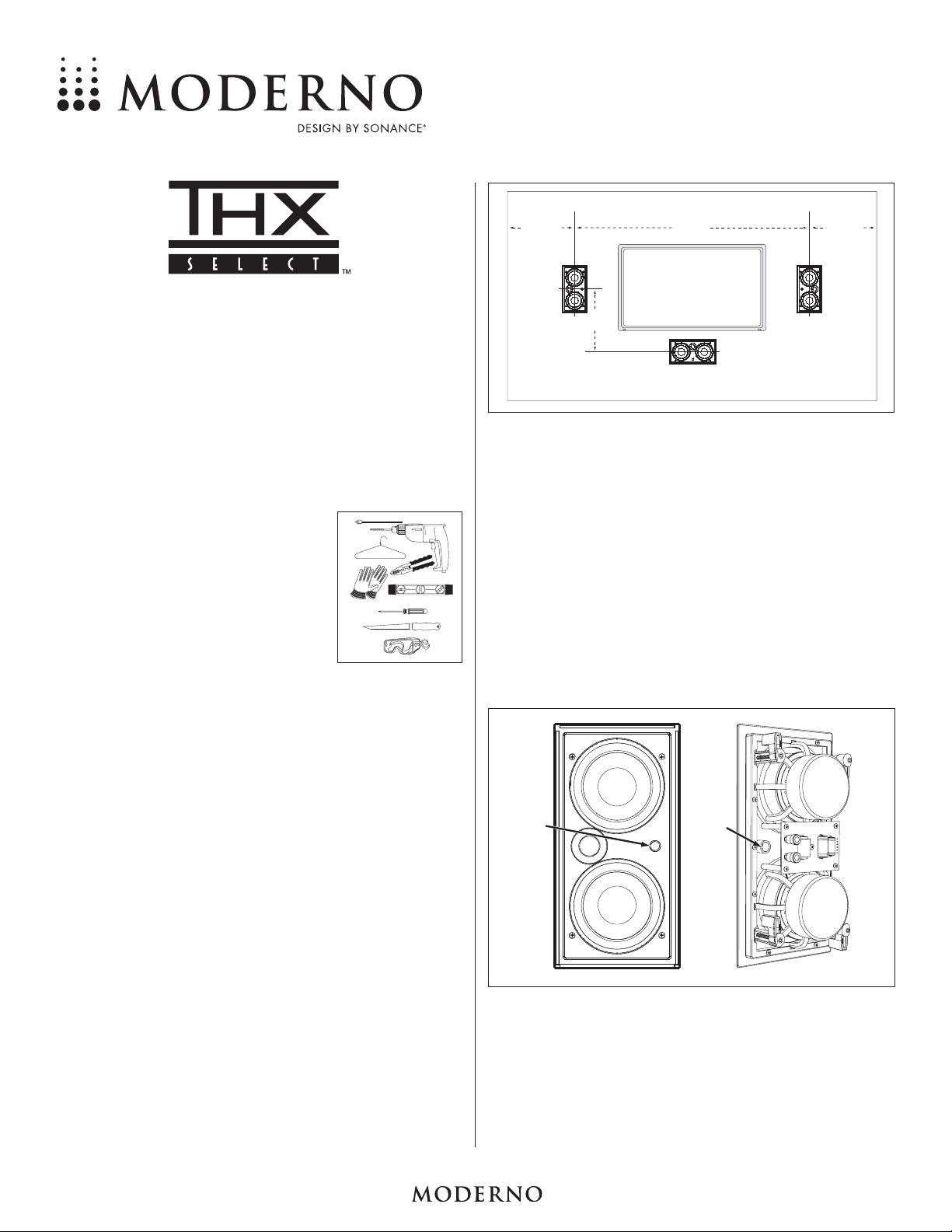
SPEAKER PLACEMENT
Home Theater Left/Center/Right Channels
• Place the left & right speakers on either side of the video screen,
from 6 feet to 10 feet apart and 38 – 42 inches from the floor,
oriented vertically with their tweeters away from the video screen.
• If possible, locate the left and right speakers at least 18 inches
away from the side walls.
• If possible, locate the center speaker at the same height as the left &
right channel speakers (38 – 42 inches from the floor), oriented
horizontally with its tweeter on top.
• If you must place the center speaker above or below a video screen,
we recommend placing it no more than 2 feet above or below the
center of the left and right speakers.
Use the illustration at the top of the next column as a guide.
N
OTE
: M
ODERNO
MLCR
SPEAKERS ARE NOT VIDEO SHIELDED
. D
ONOTLOCATE
THE SPEAKERS CLOSER THAN
20"
TO A CONVENTIONAL
(CRT)
TELEVISION OR
DAMAGE TO ITS PICTURE TUBE MAY OCCUR
.
Stereo (2-Channel)
Follow the directions for Home Theater placement for the left and
right speakers.
• If listeners will be standing instead of seated, locate the speakers
with their centers approximately 5 feet from the floor.
BEFORE INSTALLATION: IR KNOCKOUT
The Moderno MLCR speaker has a knockout for installing an IR
receiver into the speaker’s front baffle. In systems where the electronics may be placed in an inconvenient location, this allows you to
control your system’s electronics by aiming remote controls at the front
of the room instead of at the electronics.
To remove the knockout, drill it out from the rear using a drill with a
½” bit (there is a sleeve guide directly behind the knockout).
After inserting the IR receiver through the hole, seal it into the
speaker using silicone caulk (make sure that there are no gaps
around the receiver that could create air leaks) and dress the cable
behind the speaker along with the speaker wire.
MLCR
H
OME THEATER SPEAKER
INSTRUCTION M ANUAL
2'
(max.)
18"
From Side
Wall
6' – 10'
Apart
18"
From Side
Wall
IR
Knockout
IR
Sleeve

MODERNO MLCR HOME THEATER SPEAKERS
22
INSTALLING THE SPEAKERS
Step 1. Determine the location for the
speaker (see
Speaker Placement
on
page 1). Center the speaker
between the wall studs. Tap the wall
and listen for a “hollow” sound, or
use a stud finder to locate studs.
Step 2. Position the included cutout template
where the speaker is to be located
and trace the outline on the wall with
a pencil.
• Make sure the speakers are even
with each other and level.
IMPORTANT: The edges of
the cutout outline must be at least ¾” away from
any studs, to allow room for the RotoLock
®
clamps to operate.
N
OTE
: R
EADSTEP6 ABOUT RUNNING SPEAKER WIRE BEFORE DECIDING
ON THE FINAL SPEAKER LOCATIONS
.
Step 3. Drill a small hole in the center of the outline you just traced.
Step 4. Insert a coat hanger wire into the hole to feel-around for pos-
sible obstructions. If there are obstructions, patch the hole and
select another location for the speaker. Make sure that any
studs will be at least ¾” away from the edges of the cutout.
Step 5. Carefully cut the outline of the mounting hole using a keyhole
or drywall saw. Remove the drywall from the cutout.
I
MPORTANT: Make sure your amplifier’s power
is turned off before performing Step 6.
Step 6. Run the speaker cable from the
speaker outputs of your amplifier to
the speaker locations. Use highquality cable such as HomeTech
HTC100 16/4 cable. Pull the cables
through the mounting holes you cut
in the wall.
• Allow a few extra feet of cable, and
leave enough cable slack so you
can strip the insulation from the
conductors when you’re ready to
connect to the speakers.
N
OTE
: I
F SPEAKER CABLE IS TO BE RUN
THROUGH WALLS OR CEILINGS
,
THE CABLE
MUST BEUL-
AND
CL-
RATED FOR YOUR
SAFETY AND BUILDING CODE COMPLIANCE
.
Step 7. Speaker performance can be
enhanced by insulating the wall
cavity with fiberglass insulation.
When insulating speakers, it is best
to use a sheet of unfaced fiberglass
insulation behind and around the
sides of the speaker.
Step 8. Connect the positive (“+”) wire from
the amplifier to the speaker’s red
terminal. Connect the negative (“–”)
wire from the amplifier to the speaker’s black terminal.
• The speaker’s connector posts are
spring-loaded. Push the top of
each connector post down to open
the connector and insert the exposed wires into the holes in
the posts.
IMPORTANT: Be sure not to let any stray ‘+’ and ‘–’
wires touch each other. Touching wires can cause a
short-circuit that could damage your amplifier.
• Double-check that you connected amplifier “+” to speaker
“+” and amplifier “–” to speaker “–”.
Step 9. Make sure all the RotoLock clamps
are in the full clockwise position so
that they are tucked within the
mounting hole’s border. Insert the
speaker into the mounting hole.
Step 10. Tighten the four screws on the front of
the speaker baffle evenly until the
speaker is seated snugly and evenly
against the wall or ceiling.
IMPORTANT: If you are using a
drill or electric screwdriver to
tighten the screws be sure use the
lowest torque setting.
Step 11. Install the grille by placing it into
the speaker baffle. Powerful
magnets on the grille and on the
speaker baffle will hold the grille
firmly on the speaker.
Step 7
Black Cap
“—”
Red Cap
“+”
Step 8
Step 3
Step 4
Step 5
Step 10
Step 6
Step 11
Steps 1 and 2
 Loading...