

SPECTRUM SLIMLINE WALL MOUNT/RECESSED ELECTRIC FIREPLACE
Model# : SPS-50B SPS-60B SPS-74B SPS-100B
OWNER’S MANUAL
AC 120V 60Hz 1465W (5000BTUs)
WARNING
Read and understand this entire owner’s manual, including all safety
information, before plugging in or using this product. Failure to do so could
result in fire, electric shock, or serious personal injury.
CAUTION
Keep this owner’s manual for future reference. If you sell or give this
product away, make sure this manual accompanies this product.
AFFIX SERIAL NUMBER LABEL HERE
FOR FUTURE REFERENCE
BGM20200409.V12

2
IMPORTANT SAFETY INFORMATION!
WARNING
Read all instructions before installing or using this heater.
Use a dedicated 15 Amp (or higher) breaker.
This heater is hot when in use. To avoid burns, DO NOT let bare skin touch hot surfaces. If
provided, use handles when moving this heater. Keep combustible materials, such as
furniture, pillows, bedding, papers, clothes, and curtains at least 3 feet (0.9m) from the front of
the heater, and keep them away from the sides and rear.
Extreme caution is necessary when any heater is used by or near children or invalids and
whenever the heater is left operating and unattended.
Do not operate any heater after it malfunctions. Disconnect power at service panel and have
heater inspected by a reputable electrician before reusing.
Do not use outdoors.
To disconnect heater, turn controls to off, and turn off power to heater circuit at main disconnect
panel (or operate internal disconnect switch if provided).
Do not insert or allow foreign objects to enter any ventilation or exhaust opening as this may
cause an electric shock, fire, or damage the heater.
To prevent a possible fire, do not block air intakes or exhaust in any manner.
A heater has hot arcing or sparking parts inside. Do not use in areas where gasoline, paint,
flammable vapors, or liquids are used or stored.
Use this heater only as described in this manual. Any other use not recommended by
the manufacturer may cause fire, electric shock, or injury to persons.
This heater may include an audible or visual alarm to warn that parts of the heater are getting
excessively hot. If the alarm sounds (or illuminates), immediately turn the heater off and inspect
for any objects on or adjacent to the heater that may have blocked the airflow or otherwise
caused high temperatures to have occurred. DO NOT OPERATE THE HEATER WITH THE
ALARM SOUNDING (OR ILLUMINATING).
ALWAYS plug heaters directly into a wall outlet/receptacle. NEVER use with an
extension cord or relocatable power tap (outlet/power strip).
NEVER use this heater in bathrooms, laundry rooms, or any other location where the heater
could fall into a bathtub, pool, become damp, or come in contact with water.
AVOID FIRE! Regularly inspect all air vents to make sure they are free from dust, lint, or other
blockage. Unplug the unit and clean with a vacuum ONLY. DO NOT rinse or get wet.
ALWAYS mount to wall bracket before use. DO NOT set on the floor, or other surface, to use.
NEVER use a wall mount bracket from another manufacturer.
This product is not intended to be a primary heat source. It is for supplemental heat only.
INDOOR use only! NEVER use this heater outdoors! Doing so may result in electric shock!
ALWAYS disconnect this unit from the power supply before performing any assembly or
3
cleaning, or before relocating the electric fireplace.
NEVER leave this heater unattended. ALWAYS unplug this heater when not in use.
ALWAYS store this heater in a dry location. NEVER use the fireplace if it has become wet.
NEVER plug this heater into an outlet that is old, cracked, or has any loose wires or
connections. Plugging this heater into a faulty outlet could result in electric arcing within the
outlet that could cause the outlet to overheat or catch fire.
ALWAYS check your heater cord and plug connections with each use.
i) MAKE SURE the plug fits tight in the outlet. Faulty wall outlet connections or loose plugs
can cause the outlet to overheat.
ii) Heaters draw more current than small appliances. Overheating may occur even if it has
not occurred with the use of other appliances.
iii) During use check frequently to see if the plug outlet or face plate is HOT.
iv) If the outlet or face plate is HOT, discontinue use immediately and have a qualified
electrician inspect and/or replace the faulty outlets.
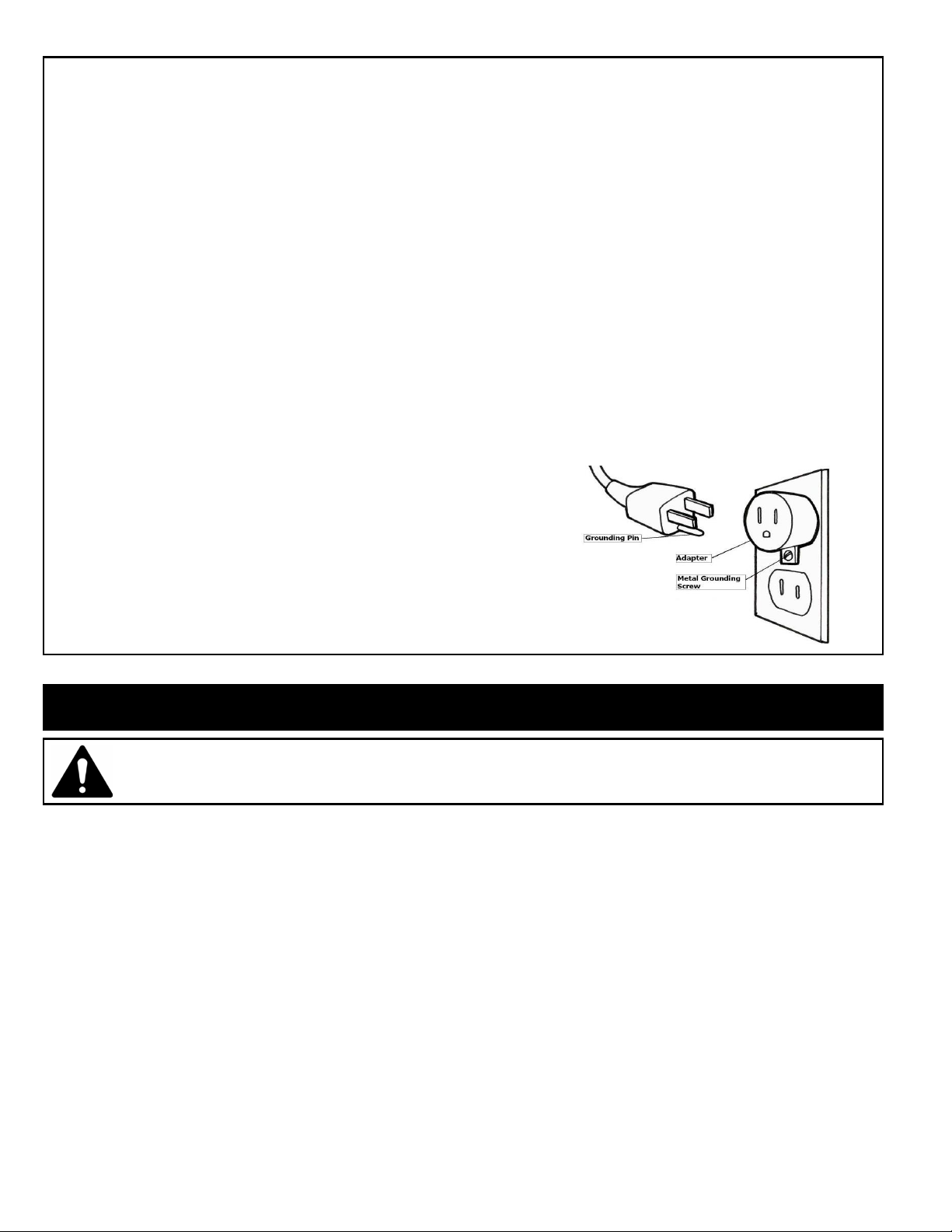
The power cord supplied with the heater has three
prongs: two flat blades (live and neutral) and one
round pin (ground). If a 3-slot receptacle is not
available, an adapter MUST be used. The adapter
MUST be properly grounded to the outlet box (see
figure at right). [NOTE: Adapter NOT INCLUDED.]
SAVE THESE INSTRUCTIONS.
Preparation
This product includes a GLASS panel. Always use extreme caution when handling
glass. Failure to do so could result in personal injury or property damage.
Remove all parts and hardware from the carton and place them on a clean, soft, dry surface. Parts and
assembly steps are grouped for wall-hanging or recessing use. Check the parts list to make sure nothing
is missing. Dispose of packaging materials properly. Please recycle whenever possible.
You will need the following tools (not included): Phillips screwdriver, stud finder, level, tape measure,
electric drill, 1/4” wood drill bit, hammer.
4
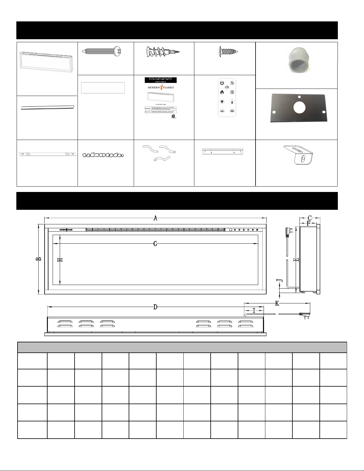
Parts and Hardware
Specification and Dimension
B -Screws (Long)
C – Drywall anchors
D – Screws (short)
A – Fireplace
E- (PEHUEHGstrip
K-Wall Bracket
(Fixed on back of firebox)
F-Side Skirt
(For wall mounting)
L-Small glacier crystals
G-Instruction manual
M - Log set
H-Remote Control
N - Metal bracket For
wall recessed purpose
I-Cable Connector
J-Cover Plate
O- “L” shape
bracket
PRODUCT DIMENSIONS
Model
Number
SPS-50B
SPS-60B
SPS-74B
SPS-100B
A B C D E F G H I J K
49-3/4"
(1264mm)
59-3/4"
(1518mm)
73-3/4"
(1873mm)
99-3/4"
(2534mm)
17"
(430mm)
17"
(430mm)
17"
(430mm)
17"
(430mm)
4-3/4"
(121mm)
4-3/4"
(121mm)
4-3/4"
(121mm)
4-3/4"
(121mm)
48-5/8"
(1235mm)
48-5/8"
(1235mm)
48-5/8"
(1235mm)
48-5/8"
(1235mm)
16-1/16
(408mm)4"(102mm)
16-1/16
(408mm)4"(102mm)
16-1/16
(408mm)4"(102mm)
16-1/16
(408mm)4"(102mm)
46"
(1168mm)
55-13/16"
(1418mm)
69-3/4"
(1772mm)
95-7/8"
(2435mm)
12"
(305mm)
12"
(305mm)
12"
(305mm)
12"
(305mm)
4-5/8"
(118mm)1"(25.4mm)
4-5/8"
(118mm)1"(25.4mm)
4-5/8"
(118mm)1"(25.4mm)
4-5/8"
(118mm)1"(25.4mm)
72"
(1829mm)
72"
(1829mm)
72"
(1829mm)
72"
(1829mm)
5
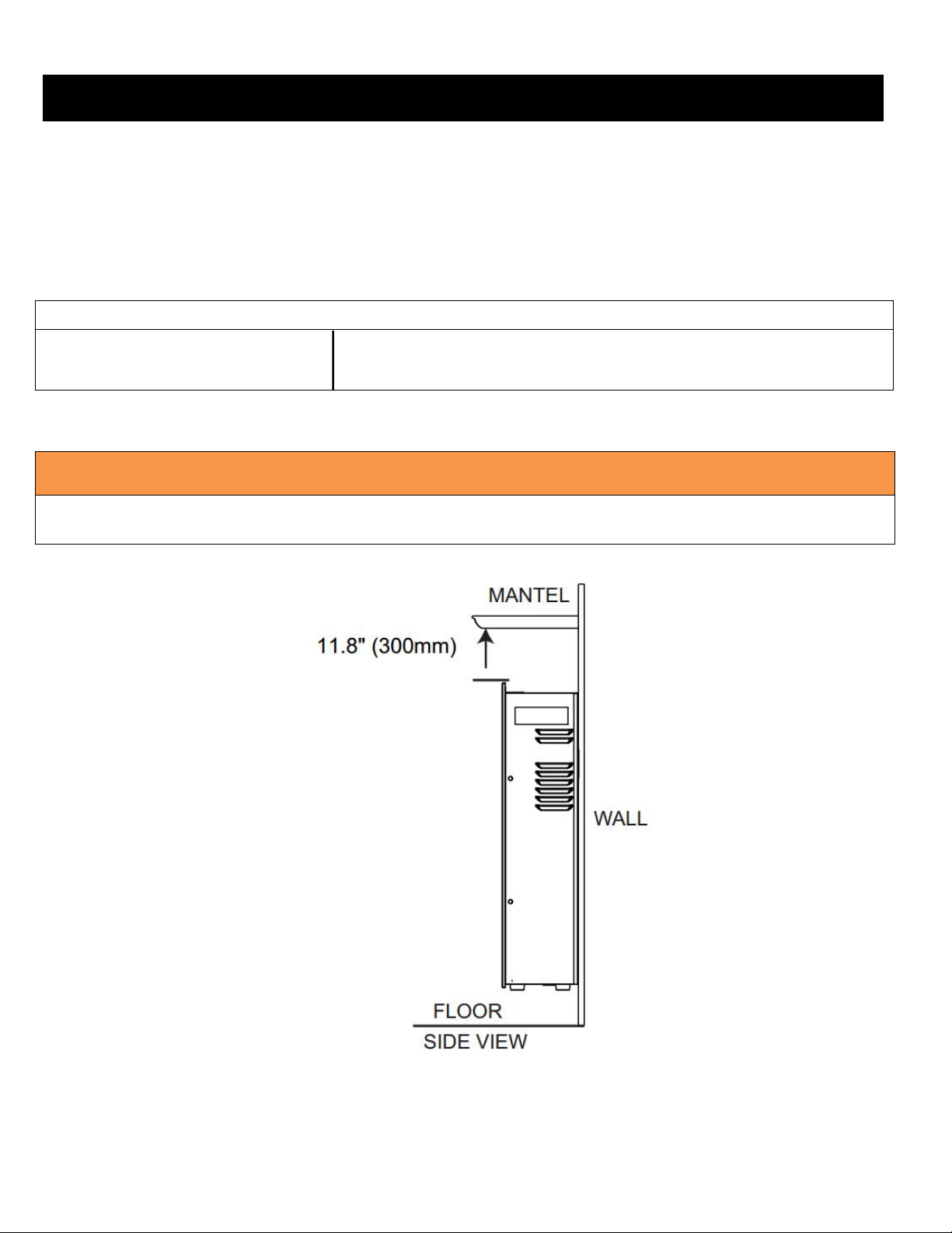
Installation and Assembly
Your appliance is a wall-mounted, recessed, and/or mantel installed appliance. Select a suitable location
Measurements are taken from the glass front.
Bottom 0" Top 11.8" (300mm) to mantel
Sides 0" Top 11.8" (300mm) to ceiling
Back 0"
WARNING
WHEN USING PAINT OR LACQUER TO FINISH THE MANTEL, THE PAINT OR LACQUER MUST BE
HEAT RESISTANT TO PREVENT DISCOLOURATION.
that is not susceptible to moisture and is away from drapes, furniture and high traffic areas.
NOTE: Follow all National and local electrical codes.
MINIMUM CLEARANCE TO COMBUSTIBLES
MINIMUM MANTEL CLEARANCES
6
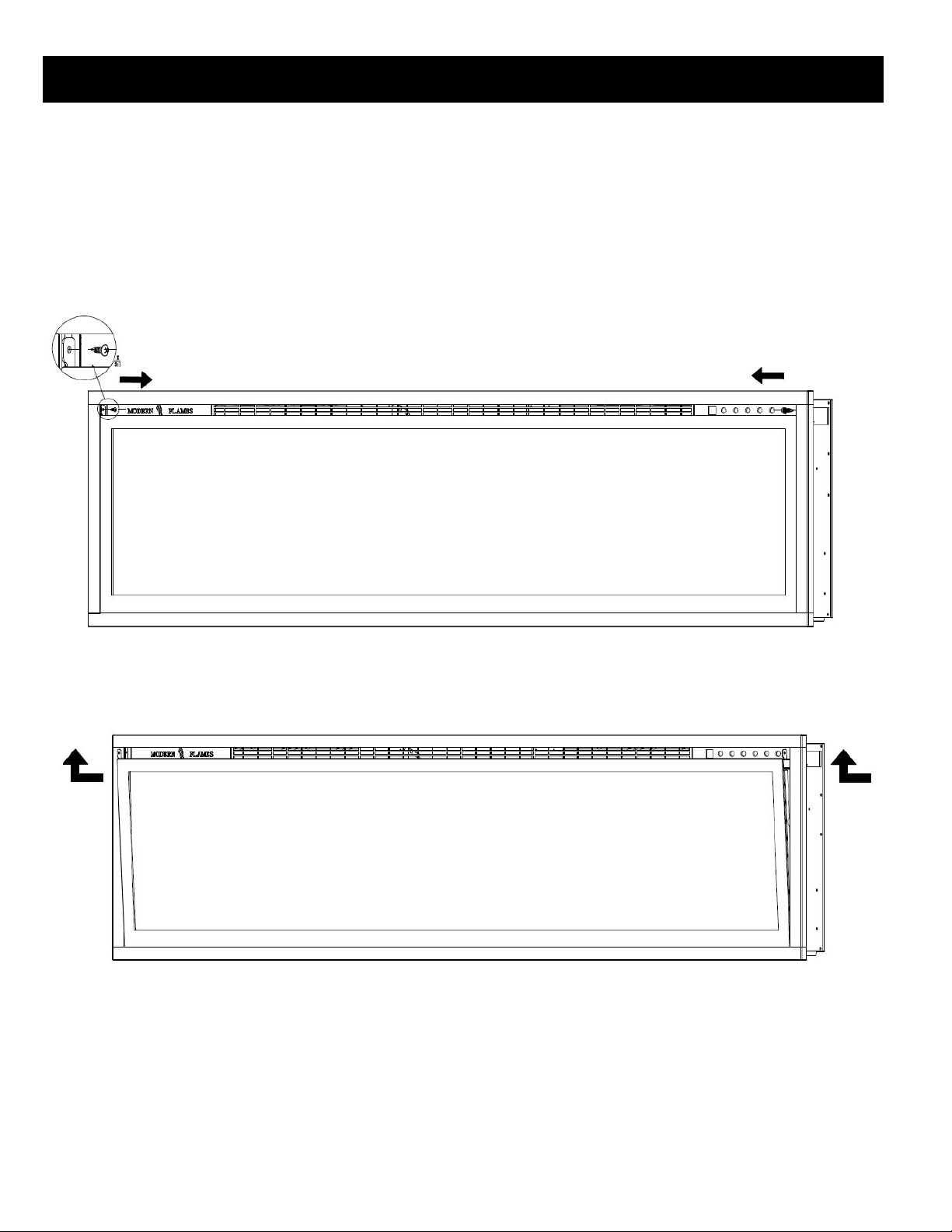
Front glass removal / installation
A. With one hand on the front glass to prevent it from falling, remove the two screws (1 per side) from the
side of the appliance (Fig. 1-1). Set the screws aside.
B. Carefully lift the front glass up and away from the appliance (Fig. 1-2 ). Place it face down on a soft,
non-abrasive surface.
C. Reverse these steps to install the front glass.
Fig. 1-1
Fig. 1-2

7
Recessed pre-installation
Due to the many different materials used on different walls, it is highly recommended that you
consult your local builder before you install this appliance on the wall.
A. Select a location that is not prone to moisture and is located at least 36” (94.1cm) away from
combustible materials such as curtain drapes, furniture, bedding, paper, etc.
B. Measure the appliance and create a rough-in frame with electrical (see below “framing”).
C. Remove the front glass (see “front glass removal / installation” section).
D. Hold the appliance up to ensure it will fit into the framing.
Power
FINISHED OPENING DIMENSIONS
Model Number A B C
SPS-50B
SPS-60B
SPS-74B
49-7/8"
(1267mm)
59-7/8"
(1521mm)
73-7/8"
(1876mm)
16-1/4"
(412mm)
16-1/4"
(412mm)
16-1/4"
(412mm)
4" min.
(102mm min.)
4" min.
(102mm min.)
4" min.
(102mm min.)
SPS-100B
(2537mm)
99-7/8"
16-1/4"
(412mm)
4" min.
(102mm min.)

8
Fully recessed installation
A. Remove power cord and complete hardwiring (see “hardwiring installation” section).
B. Mark location for the screws according to the dimensions as below. (Figure 2-1)
Figure 2-1
C. Fix the two metal brackets (N) (1per side), with 4 screws (B) (supplied) through wood stud. (Figure 2-2)
Wood Stud
Figure 2-2

9
D. Remove the four screws (2 per side) from the side of the appliance and remove the brackets
(Fig. 2-3). Set the screw/brackets aside.
Figure 2-3
E. Insert the appliance into the rough-in frame and then secure it by installing 4 screws and two brackets
(supplied) through the side holes (Fig. 2-4).
Figure 2-4 Figure 2-5
F. Install media (see “media installation” section). You must complete this step before moving onto
the next step.
G. Re-install the front glass

10
Wall mounted installation
Due to the many different materials used on different walls, it is highly recommended
that you consult your local builder before you install this appliance on the wall.
SPS-50B Wall Bracket Illustrated
A. NOTE: A dedicated 15 Amp (or higher) breaker is required.
B. Select a location that is not prone to moisture and is located at least 36" (914mm)
away from combustible materials such as curtain drapes, furniture, bedding, paper,
etc.
C. Have two people hold the appliance against the wall to determine the final
location.
D. Place unit face down on a soft, non-abrasive surface. Remove the wall bracket
(K) from the back of the unit by removing the screws, refer to Figure 1.
E. Mark location, then mount the bracket(s) onto the wall using the supplied screws.
This bracket MUST have the hooks facing upward and be level. NOTE: It is
strongly recommended that the
mounting bracket (K) be
Screwed into the wall studs
where possible. If the wall
studs cannot be used, ensure
the supplied plastic anchors are used to affix the bracket to the wall and the
bracket is adequately secured.
F. With the wall mounting bracket installed have two people lift the appliance up and
insert the two hooks on the bracket into the two slots on the back of the appliance.
G. Check the appliance for stability ensuring that the bracket will not pull free from
the wall.
H. Install the side skirt panels (F) to each side of firebox.

11
“L” Shape bracket installation
Fig 3-1
Fig 3-2
Fig 3-3
(D)
SPS-60/74/100B Wall Bracket Illustrated SPS-50/60/74/100B Side skirt illustration
A.Remove the silver screw at the bottom of the appliance. (Fig 3-1). Set the screw
aside.
(F)
B.Using the screw previously removed, attached the L-bracket (O) (supplied) to the
bottom of the fireplace box.(Fig 3-2)
C. Install the plastic anchor (C) into the dry wall, then install the screw (B) (supplied)
into the hole of the L-bracket into the wall anchor to secure the fireplace from coming
off the hooks.(Fig 3-3)

12
Hard wiring installation
WARNING
TURN OFF THE APPLIANCE COMPLETELY AND LET COOL BEFORE SERVICING. ONLY A QUALIFIED SERVICE
PERSON SHOULD SERVICE AND REPAIR THIS ELECTRIC APPLIANCE.
HARD WIRING CONNECTION
If it is necessary to hard wire this appliance, a qualified electrician must remove the cord connection, and wire
the appliance directly to the household wiring. NOTE: A dedicated 15 Amp (or higher) breaker is required.
This appliance must be electrically connected and grounded in accordance with local codes if hard wired. In
the absence of local codes, use the current CSA C22.1 CANADIAN ELECTRICAL CODE in Canada or the
current ANSI/NFPA 70 NATIONAL ELECTRICAL CODE in the United States.
TURN OFF POWER FROM CIRCUIT BRACKER FIRST
A. Remove the cover plate from the right side bottom of the appliance by removing the three screws,
as shown above. (SEE FIG.1)
B. Remove the wire nuts from the power cord. The power cord may be discarded. (SEE FIG.2)
C. Take the new cover plate, supplied in the hardware bag and punch out the 7/8" (22.2mm) hole and install
cable connector through into the junction box. Snap the cable connection clamp onto the supply wires.
D. Using the wire nuts, connect the ground green wires (G), the common white wires (N)
together, then the hot black wires (L), (SEE FIG.3)
E. Re-install the cover plate using the three screws, as shown in FIG.1.
Cable connector
( I )
Cover plate ( J )

13
Driftwood Logs and Glacier Crystal installation
A. Glass front must be removed and the appliance must be mounted in its final location
before the driftwood logs ( M ) and glacier crystals ( L ) are installed.
B. Place the ember bed strip ( E ) in position.
C. Install logs ( M) first, then add Glacier Crystals ( L ) around logs.
D. Photo below shows recommended log placement but logs may be arranged to customer’s liking.
Ember Bed Strip ( E )
Log 1
Log 7
50” Set Contains 8 Logs
1
2
60” Set Contains 9 Logs
1
2
74” Set Contains 12 Logs
1
2
Log 2
Log 8
5
4
3
6 7
Log 3
8
Log 9
Log 4
Log 10
Log 5
Log 6
Log 12Log 11
Spectrum Slim
Log Set Sizes:
50”, 60”, 74” & 100”
7
8 9
8
9
4
3
3
5
4
5 6
7
6
Log sets may vary and are subject to change.
10
12
11
100” Set Contains 16 Logs
1
2
6
3
4
5
7
8
1
2
3
4
6
5
7
8

14
Operation
Read and understand this entire owner’s manual, including all safety information,
before plugging in or using this product. Failure to do so could result in electric shock,
fire, serious injury, or death.
Power
BUTTON
FUNCTION
ACTION & INDICATION
POWER
ON: Enables control panel functions and
remote control. Turns on flame.
OFF: Disables control panel functions and
remote control. Turns off flame.
1. Press once: Indicator light turns on.
Power turns on. All functions enabled.
2. Press again: Flame turns off. Unit goes
to standby. All functions turn off.
MEDIA
MEDIA BED button: Turns on media bed
and changes color.
NOTE: color effect stays on until power
button is turned off.
NOTE: this fireplace has memory function
for ember bed.
1. Press once: Turns on ember bed.
2. Press again until desired color is
reached. In total ten colors and one fade
mode.01-02-03-04-05-06-07-08-09-10-11
Control Panel
Plug the power cord into a dedicated 110~120 Volt 15 Amp grounded outlet (see IMPORTANT
SAFETY INFORMATION on Pages 2 and 3). Make sure the outlet is in good condition and the plug
is not loose. NEVER exceed the maximum amperage for the circuit. DO NOT plug other appliances
into the same circuit.
Methods of Operation
This electric fireplace can be operated by the TOUCH ON CONTROL PANEL, located on the UPPER
right corner of the fireplace or by the battery-powered REMOTE CONTROL.
Remote control ( H )
Touch-on Control Panel Operation

15
FLAME
FLAME button: Changes flame color.
NOTE: color effect stays on until power
button is turned off.
NOTE: this fireplace has memory function
for flame.
1. Press once: Flame color illuminates.
2. Press again until desired color is
reached. In total, ten colors for flame and
one fade mode From 01-02-03-04-05-06-
07-08-09-10-11.
HEATER
HEATER button: Turns heater on and off.
NOTE: The heater only works when the
flame is on. If the flame is off, the heater
will not turn on.
NOTE: To prevent overheating, the heater
fan will blow cool air for 8-10 seconds
before the heater turns on and after the
heater turns off.
Turns the heater and blower on/off.
Settings:
H0 - Heater and blower off
H1 - Low Heater on with 750W
H2 - High Heater on with 1500W
NOTE: Press and hold the heater button for 5
seconds to lock/unlock the heater and thermostat.
TIMER
TIMER button: Controls timer settings to
turn off fireplace at selected time.
Settings range from 30min to 8 hours.
1. Press once: Indicator light turns on.
Timer defaults to 0.5 hours.
2. Press again until desired setting is
reached.
TEMP
1. Press once: Touch panel indicator becomes active.
2. Press again until desired temperature is reached. Digital display shows settings 0-10.
Table below shows corresponding temperatures:
NOTE: Press the button for 5 seconds to switch between °C and °F

16
Remote Control Operation
BUTTON
FUNCTION
ACTION & INDICATION
POWER
ON: Enables control panel functions and
remote control. Turns on flame.
OFF: Disables control panel functions and
remote control. Turns off flame.
1. Press once: Indicator light turns on.
Power turns on. All functions enabled.
2. Press again. Flame turns off. Unit goes
to standby. All functions turn off.
FLAME
SPEED
Flame speed button: Controls the speed
of the flame.There are 3 flame speed
settings: 01 (slowest), 02 (Medium), 03
(fastest).
1. Press once: Indicates current flame
speed.
2. Press again until desired setting is
reached. Display shows the setting.
The Default setting is 02 (medium speed)
FLAME
FLAME button: Changes flame color.
NOTE: color effect stays on until power
button is turned off.
NOTE: this fireplace has memory function
for flame.
1. Press once: Flame color illuminates.
2. Press again until desired color is
reached. In total, ten colors for flame and
one fade mode.From 01-02-03-04-05-06-
07-08-09-10-11.
FLAME
BRIGHT-
NESS
FLAME brightness button: Makes flame
dimmer and brighter.
NOTE: Flame stays on until power button
is turned off.
1. Press once: Flame brightness enabled.
2. Press again until desired setting is
reached. From F5-F4-F3-F2-F1
HEAER
HEATER button: Turns heater on and off.
NOTE: The heater only works when the
flame is on. If the flame is off, the heater
will not turn on.
NOTE: To prevent overheating, the heater
fan will blow cool air for 8-10 seconds
before the heater turns on and after the
heater turns off.
Turns the heater and blower on/off.
Settings:
H0 - Heater and blower off
H1 - Low Heater on with 750W
H2 - High Heater on with 1500W
NOTE: Press and hold the heater button for 5
seconds to lock/unlock the heater and thermostat.
TIMER
TIMER button: Controls timer settings to
turn off fireplace at selected time.
Settings range from 30min to 8 hours.
1. Press once: Indicator light turns on.
Timer defaults to 0.5 hours.
2. Press again until desired setting is
reached.

17
TEMP
1. Press once: Touch panel indicator becomes active.
2. Press again until desired temperature is reached. Digital display shows settings 0-10.
Table below shows corresponding temperatures:
NOTE: Press the button for 5 seconds to switch between°C and°F
MEDIA
MEDIA BED button: Turns on media bed
and changes color.
NOTE: color effect stays on until power
button is turned off.
NOTE: this fireplace has memory function
for ember bed.
1. Press once: Turns on ember bed.
2. Press again until desired color is
reached. In total ten colors and one fade
mode.01-02-03-04-05-06-07-08-09-10-11
MEDIA
BRIGHT-
NESS
MEDIA brightness button: Makes media
bed dimmer and brighter.
NOTE: LED MEDIA light brightness stays
on until power button is turned off.
1. Press once: Brightness becomes active.
2. Press again until desired setting is
reached. In total 5 levels.
From L5 - L4 - L3 - L2 - L1
NOTICE
When the heater is first turned on, a slight odor may be present. This is normal and
should not occur again unless the heater is not used for a long period of time.
NOTICE
To improve operation, aim the remote control at the front of the fireplace. DO NOT
press the buttons too quickly. Give the unit time to respond to each command.
Temperature Limiting Control
This heater is equipped with a Temperature Limiting Control. Should the heater reach an unsafe
temperature, the heater will automatically turn OFF. To reset:
1. Unplug the power cord from the outlet. Wait 5 minutes.
2. Inspect the fireplace to make sure no vents are blocked or clogged with dust or lint. If they are,
use a vacuum to clean the vent areas.
3. Plug the power cord back into the outlet.
4. If the problem continues, have your outlet and wiring inspected by a professional.
Remote Control Battery Information
Remote control uses one CR2025 battery (Included)

18
NEVER dispose of batteries in fire. Failure to observe this precaution may result in an
explosion. Dispose of batteries at your local hazardous material processing center.
Care and Maintenance
Cleaning
ALWAYS turn the heater OFF and unplug the power cord from the outlet before
cleaning, performing maintenance, or moving this fireplace. Failure to do so could result in
electric shock, fire, or personal injury.
NEVER immerse in water or spray with water. Doing so could result in electric shock,
fire, or personal injury.
Risk of electric shock! DO NOT OPEN any panels! No user-serviceable parts inside!
ALWAYS turn the heater OFF and unplug the power cord from the outlet before
cleaning, performing maintenance, or moving this fireplace. Failure to do so could result in
electric shock, fire, or personal injury.
WARNING! NO SERVICING of the internal or electrical parts should be performed by the
consumer. Do not service the unit yourself.
Metal:
Buff using a soft cloth, slightly dampened with a citrus oil-based product.
DO NOT use brass polish or household cleaners as these products will damage the metal trim.
Glass:
Use a good quality glass cleaner sprayed onto the cloth or towel. Dry thoroughly with a paper
towel or lint-free cloth.
NEVER use abrasive cleansers, liquid sprays, or any cleaner that could scratch the surface.
Vents:
Use a vacuum or duster to remove dust and dirt from the heater and vent areas.
Plastic:
Wipe gently with a slightly damp cloth and a mild solution of dish soap and warm water.
NEVER use abrasive cleansers, liquid sprays, or any cleaner that could scratch the surface.
Maintenance
Electrical and Moving Parts:
The fan motors are lubricated at the factory and will not require lubrication.
Electrical components are integrated in the fireplace and are not serviceable by the consumer.
Storage:
Store heater in a clean dry place when not in use.

Spare Parts List
PART DESCRIPTION
FRONT GLASS 04-00001 04-00002 04-00003 04-00004
ACRYLIC PLASTIC PANEL 03-00001 03-00002 03-00003 03-00004
STEP MOTOR 01-00001
BLOWER 01-00002
HEATER 01-00010
PLASTIC STRIP 03-00005 03-00006 03-00007 03-00008
WALL MOUNTING BRACKET 02-00001 02-00002
LED FLAME LIGHT 01-00003
LED EMBER LIGHT 01-00004
REFLECTOR SPINDLE
REMOTE CONTROL
TOUCH-ON CONTROL PANEL
REMOTE RECEIVER 01-00011
CIRCUIT BOARD 01-00007
POWER BOARD 01-00008
HARDWARE KIT 02-00010
CRYSTAL, CLEAR GC Diamond 3.5
CRYSTAL, SMOKED GC Smoke 3. 5
LOG SET
THERMOSTAT (NTC)
FRONT METAL TRIM KIT (4 PIECES)
GLASS FACE FOR TOUCH CONTROL 04-00013
MODERN FLAMES LIGHT UP GLASS LOGO
METAL SIDE BRACE FOR PLASTIC PANEL 02-00015
METAL TOP BRACE FOR PLASTIC PANEL
FLAME ENHANCER
METAL SIDE PANEL FOR WALL MOUNT INSTALL
Model: SPS-50B Model: SPS-60B Model: SPS-74B Model: SPS-100B
02-00003 02-00004 02-00005 02-00006
05-00001 05-00002 05-00003 05-00004
02-00011 02-00012 02-00013 02-00014
02-00016 02-00017 02-00018 02-00019
02-00020 02-00021 02-00022 02-00023
MODERN FLAMES PART NUMBERS
01-00005
01-00006
01-00009
04-00014
02-00024
INDIVIDUAL LOGS PART NUMBERS
LOG #1 05-00005
LOG #2 05-00006
LOG #3 05-00007
LOG #4 05-00008
LOG #5 05-00009
LOG #6 05-00010
LOG #7 05-00011
LOG #8 05-00012
LOG #9 05-00013
LOG #10 05-00014
LOG #11 05-00015
LOG #12 05-00016
19

DO NOT RETURN TO STORE!
CALL US FIRST
For immediate help with installation, product information or
if your product arrives damaged, please call our toll free number at:
1-877-246-9353
(Monday - Friday, 8:00AM - 5:00PM, AZ Mountain Time)
Or email us at:
customerservice@modernflames.com
OUR STAFF IS READY TO PROVIDE ASSISTANCE
20
 Loading...