

Page 1
FusionFireTM Steam Fireplace
I
M
NSTALLATION & USER’S
ANUAL
Copyright 2017-2018, all rights reserved
U.S. and Foreign Patents Pending
Rev. 7
Page 2

FusionFire 60
Version 1
Models
The manual covers the following models:
Contents
1.0 Introduction ................................................... 4
1.1 General ...................................................... 4
1.2 Technology ................................................ 4
1.2.1 Specifications ..................................... 4
1.2.2 Basic and Optional Features ............... 4
1.2.3 Controllable Features ......................... 4
2.0 User Instructions ........................................... 5
2.1 Important Inform a ti o n ................................. 5
2.2 Operating Instructions ................................ 5
2.2.1 Guidelines .......................................... 5
2.2.2 Startup Using the Keypad Interface .... 6
2.2.3 Shutdown Using the Settings Pad ....... 6
2.2.4 Operational Status Indicators .............. 6
3.0 Installation Instructions .................................. 7
3.1 General ...................................................... 7
3.1.1 Unpacking the Fireplace ..................... 7
3.1.2 Protective Film/Cardboard .................. 7
3.2 Fitting the Fireplace ................................... 7
3.2.1 Location of the Fireplace..................... 7
3.2.1.1 Clearances .................................. 7
3.2.2 Product Dimensions ............................ 7
3.2.2.1 Product Drawing .......................... 8
3.2.3 Centering ............................................ 8
3.3 Preparation ................................................ 8
3.3.1 Framing for Wall Build-In .................. 10
3.3.1.1 Framing Details ......................... 10
3.3.2 Electrical Power Connections ........... 11
3.3.2.1 Connect: Flame Only (No Heater)
11
3.3.2.2 Connect: Flame & Heater .......... 11
3.3.3 Water Supply ................................... 11
3.3.3.1 Water purity .............................. 11
3.3.3.2 Water line connection ................ 11
3.3.3.3 Manual fill option ....................... 11
3.3.4 Venting ............................................. 11
3.3.4.1 Optional venting requirements .. 11
3.3.4.2 Steam safety ............................. 12
3.4 Installation ............................................... 12
3.4.1 Mat and Water Leak Sensor ............. 12
3.4.2 Fitting the Fireplace .......................... 12
3.4.2.1 Fastening Tabs ......................... 12
3.4.3 Connecting the Fireplace ................. 13
3.4.3.1 Water Connections ................... 13
3.4.3.2 Making Electrical Connections .. 14
3.4.3.3 Verifying Electrical Connections 14
3.4.4 Finishing the wall ............................. 17
3.4.4.1 Drywall Stops ............................ 17
3.4.4.2 Drywall Placement .................... 17
3.4.4.3 Construction Barrier .................. 17
3.4.5 Final start-up procedure ................... 17
3.4.5.1 Filling the Reservoir .................. 17
3.4.5.2 Power Up .................................. 18
3.4.5.3 Fire Bed Media Installation ........ 19
3.4.5.4 Draining the Reservoir/Boiler .... 19
Page | 2
Page 3
3.5 Installation FAQ’s ..................................... 20
At the end of its useful life
3.6 Troubleshooting ....................................... 21
3.6.1 Fault Diagnosis Chart ....................... 21
Recycle in accordance with
Code of Federal
Regulations (CFR), Title
40, Part 273. This device is
classified as electrical and
electronic equipment
As such, it must not be
disposed of with household
waste.
please take this product to
an appropriate recycling
center or collection point.
You can find your nearest
recycling drop off point by
contacting your locality’s
waste management office.
NOTE: The advisories on this page will be updated
with the appropriate information upon completion of
U.L. compliance testing.
This product is guaranteed for 2 years from the date of installation, as set out in the terms and conditions of sale between Modern
Flames and your local dealer. This guarantee will be invalid, to the extent permitted by law, if the appliance has not been installed and
operated as detailed in the Installation and User Instructions. The guarantee will only be valid during the second year, to the extent
permitted by law, if the appliance has been regularly maintained by the customer as detailed in the maintenance section of the
Installation and User Guides.
Page | 3
Page 4

1.0 Introduction
This document provides user operating information
and installation instructions for the FusionFire™
electric fireplace product. It is intended to be
installed as a built-in appliance in a new or existing
site.
1.1 General
The Modern Flames FusionFire™ Steam Fireplace
combines the natural, 3-dimensional flame
appearance of a gas fireplace with the safety and
ease of installation associated with an electric
fireplace.
The Modern Flames FusionFire™ Steam Fireplace is
designed to replace gas fireplaces without
compromising the realism of the flames.
This product delivers a 3-dimensional natural
random flame appearance similar to a gas fireplace,
but without the associated installation restrictions
and heat issues.
1.2 Technology
1.2.1 Specifications
• LCD User display: Displays settings, status,
and user guidance.
• Keypad: Allows operation without a remote
control.
• Remote Control: Wireless “TV” type remote
(Infrared technology).
• Utilizes a standard dedicated 120 VAC @
60Hz 20A circuit for the flame presentation
function.
• Utilizes an additional standard dedicated 120
VAC @ 60Hz 20A circuit for the room heater
function (heater included with each unit,
hookup optional).
• FauxFire® technology is a patented
simulated flame system that utilizes steam
and lighting techniques to create a realistic
flame effect.
1.2.2 Basic and Optional Features
• Produces desirable humidity as a byproduct
of steam production.
• Auxiliary heater unit (hookup is optional):
Provides additional warmth for cold climate
installations.
• Firebox Liner (sold separately): The inside of
the firebox is designed to accept various
decorator liners.
• Faux log set (sold separately)
1.2.3 Controllable Features
• Fireplace On/Off
• Flame Height: User may adjust the flame
height in 6 flame setti ngs.
• Flame intensity: User may adjust flame effect
light source from low to high.
• Auxiliary Heat On/Off and Temperature
Increase/Decrease in 6 settings
• User Display prompt when water filter
replacement is requited
During operation, the steam boiler heats a volume of
water safely under controlled low pressure to create
the proper conditions for a steady stream of steam
that turns immediately into water vapor when it is
released from a manifold. The shape of this vapor
emission is very important to the realism of the fire
simulation.
A lighting assembly is strategically located to
illuminate the steam.
• Water Source: Standard ¼” water line
(included) for plumbed installations allows
automatic filling. If no water source available,
manual water filling allows for 12 hours of
continuous use.
• Integrated water filter system ensures clean
operation and full rated product life.
Page | 4
Page 5

can cause
to cool before
WARNING!
reuse.
!
2.0 User Instructions
2.1 Important Information
8. Use this appliance only as described in this
manual. Any other use not recommended by
the manufacturer may cause fire, electric
shock or injury to persons.
9. Do not attempt to make electrical or
mechanical adjustments, or repairs without
the services of qualified personnel.
WARNING: Improper installation, adjustment,
alteration, service or maintenance
injury or property damage. Refer to this manual.
For assistance or additional information, consult
a qualified installer.
Fireplace internal components become hot when
running. Keep children and adults away from hot
surfaces to avoid burns. Internal components will
remain hot for an extended period of time after
shutdown. Allow these areas
touching.
2.2 Operating Instructions
2.2.1 Guidelines
When us ing electrical heaters, basic precautions
should always be followed to reduce the risk of fi re,
electric shock and injury to persons, including the
following:
10. Do not make any electrical connections,
even temporary, under carpeting, along
baseboards, etc. All electrical connections to
this appliance must be done within walls and
in accordance with local electrical codes.
11. The appliance is hardwired and has no main
switch. (Caution: If servicing this unit, turn off
power at the main circuit breaker.)
12. SAVE THESE INSTRUCTIONS
Do not operate this appliance if damaged or
has malfunctioned. Call a qualified service
technician to inspect it. Replace any part of
the electrical system if necessary before
1. Read all instructions before installing or
using this appliance.
2. Internal components are hot when in use. To
avoid burns, do not let bare skin touch hot
surfaces.
3. Extreme caution is necessary when any
electrical appliance is used by or near
children whenever it is left operating and
unattended.
4. Do not use outdoors.
5. To disconnect, turn controls to OFF and turn
OFF power at the main circuit breaker.
6. Do not block air intakes or exhaust in any
manner.
7. Do not use in areas where gasoline, paint or
flammable vapors or liquids are used or
stored.
Page | 5
Page 6
2.2.2 Startup Using the Keypad Interface
Figure 1
Figure 2
Open the display panel by pushing down on the
small rectangle located in the lower right area of the
fireplace screen (see Figure 1). The display panel
will popup.
To the left of the display, press the power button on
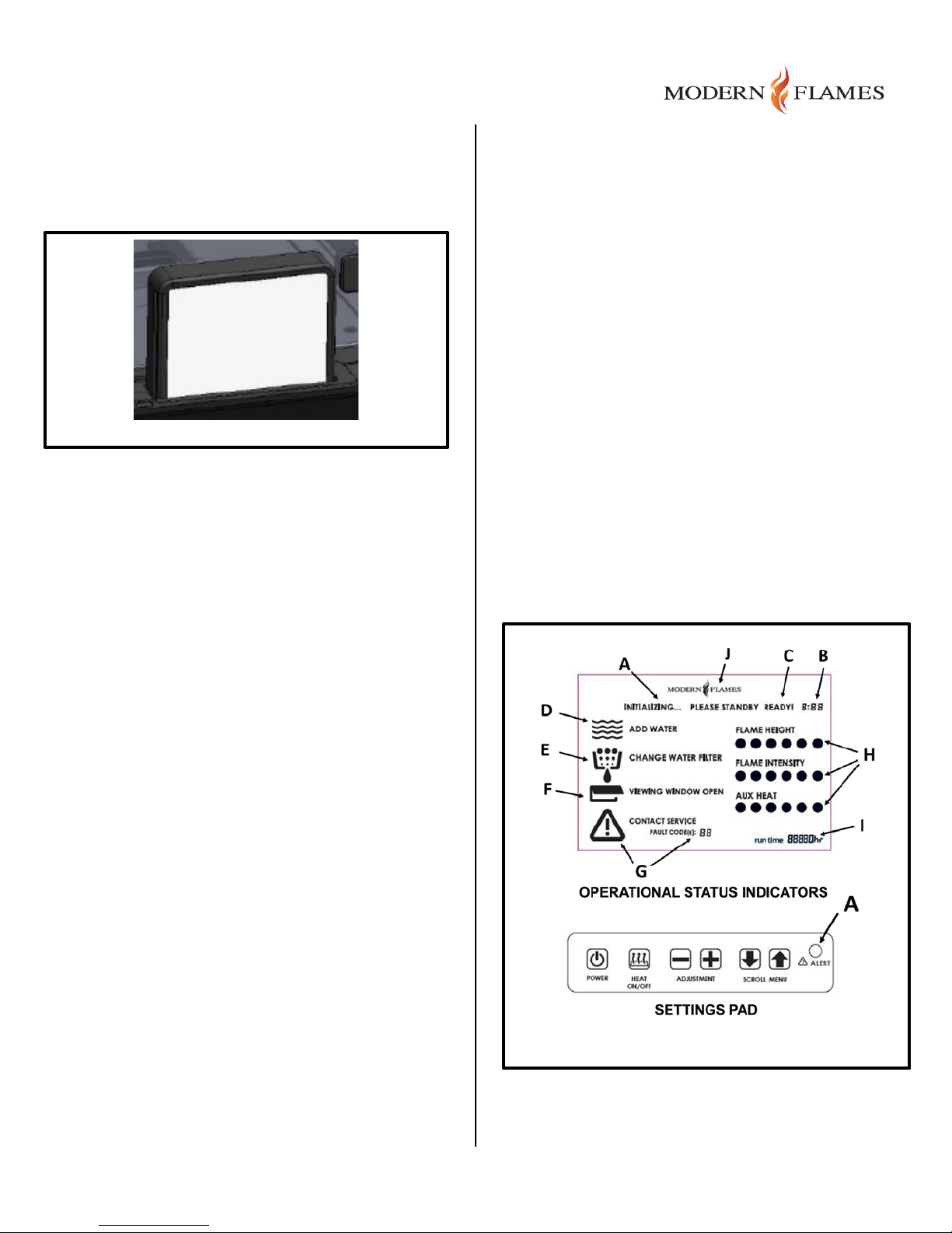
the Settings Pad (Figure 2) and the “Initializing”
“Please Standby” display will appear while the
controller boots up and the steam supply is heated
(Approx. 3 minutes).
As soon as the fireplace is ready to operate, you will
see a “Ready” display. After a short delay, the
simulated fire will star t and the display backlight will
turn off. The display may be pushed down again to
lock it into place, hiding it fr om view.
E – When it is necessary to replace the water filter,
the “Change Water Filter” indicator will come on.
F – If the fireplace’s viewing window (glass) is left
open or has not been closed properly, the “Viewing
Window Open” indicator warns that it should be
closed.
G – If the fireplace controller has detected a Fault
condition affecting proper operation, the “Contact
Service” and “Fault Code(s)” indicators will come on.
Please call a service technician to resolve these
types of problems.
H – The flame height, flame intensity and Aux. heat
settings are setup according to customer
preferences. These are confirmed by 3 rows of
indicators to view adjustments as they are entered.
Settings Pad – This entry pad allows for the power
to be turned on/off, the Aux. Heat to be turned on/off
and the operating menu to be accessed. The
fireplace settings may generally be changed by
scrolling through the menu and using the “-“ and “+”
adjustment buttons to mak e changes. If a Fault is
detected, the “Alert” indicator and corresponding
display will be activated.
Note: The wireless remote control may also be used
to operate the fireplace.
2.2.3 Shutdown Using the Settings Pad
Press the power button again and the simulated
flame will shut off.
2.2.4 Operational Status Indicators
In Figure 2 there is an illustration of the fireplace’s
status indicators. The operational states are:
A – When the fireplace is first turned on and is
powering up, the “Initializing…” indicator will come
on, followed by the “Please Standby” indicator.
B – A timer shows how much time has elapsed since
the fireplace was first powered up. Typically, this
should not be more than a few minutes.
C – When the startup sequence is complete, the
“Ready!” indicator will appear and the unit is fully
operational.
D – When the water reservoir it low, the “Add Water”
indicator will come on to warn that more water
should be added for continued operation.
Page | 6
Page 7
3.0 Installation Instr uctions
Model
Viewing
Firebox
Framing
FusionFire
24” x
31¾” x
32” x
Figure 3
3.1 General
A qualified electrician should add one (or two when
connecting the heater) dedicated 20 Amp, 120 Volt
circuit per local building codes. NOTE: Follow all
national and local electrical codes.
3.1.1 Unpacking the Fireplace
Follow the procedure below to unpack and inspect
the fireplace:
3.1.2 Protective Film/Cardboard
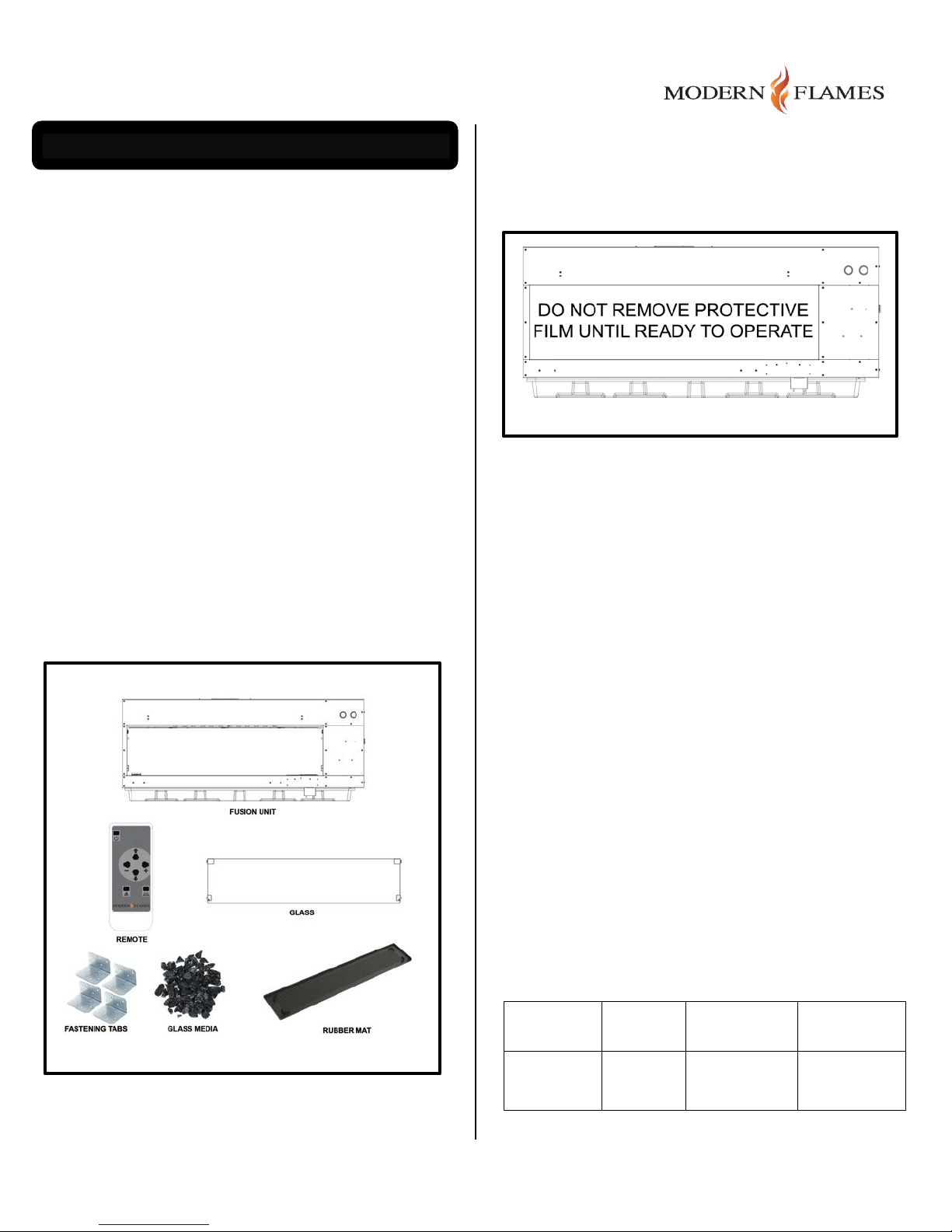
Leave the factory-applied protective film/cardboard
on all front facing surfaces until ready to operate the
fireplace (see Figure 4). This will protect from dust
contamination and scratches during installation.
1. Carefully remove the packing from around the
unit and set aside parts that are wrapped
separately.
2. Check that all parts and accessories are
accounted for before disposing of any
packaging. Note: The glass and some other
parts are protected inside the fireplace and may
not be unpacked until start-up.
3. If necessary, keep the original packaging for
future transport and/or storage.
Refer to Figure 3 to review the general contents of
the packaging.
Figure 4
3.2 Fitting the Fireplace
3.2.1 Location of the Fireplace
The fireplace may be installed at any indoor location.
However, when choosing a location, please keep in
mind the following guidelines:
• Install out of direct sunlight for maximum
performance.
• Select a suitable location that is no t susceptible
to moisture and is a safe distance from
flammable items like drapes, furniture or high
traffic areas.
• If any of the power connection points are
damaged, it must be repaired by the
manufacturer, authorized dealer or certified
technician.
• Make sure that it is possible to connect the
fireplace power directly using a dedicated line
back to the breaker box with a code-compliant
connection to the installation location.
3.2.1.1 Clearances
Do not lean or drape cloth or other flammable
materials on the fireplace or block air ways.
3.2.2 Product Dimensions
Number
60
Area
60”
Dim.
73.86”
Dim.
74¼”
Page | 7
Page 8
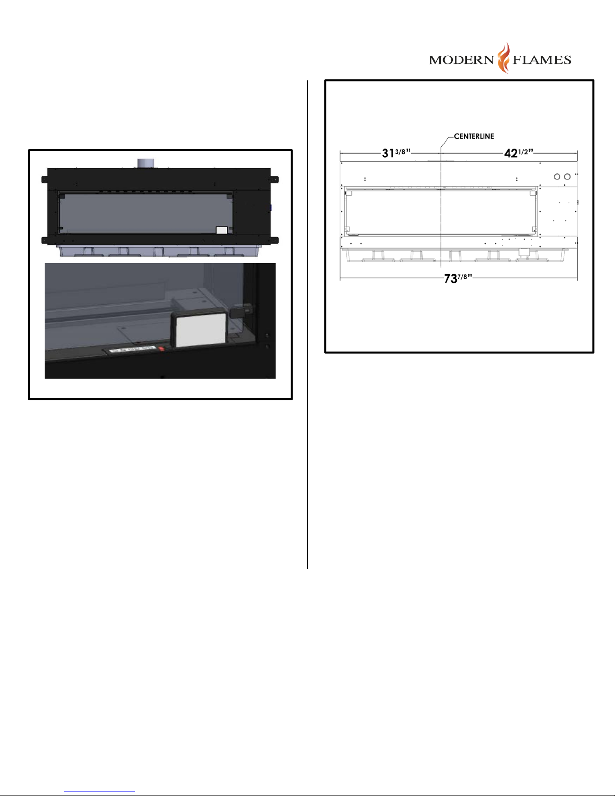
3.2.2.1 Product Drawing
Figure 6
Refer to the detailed product drawing in Figure 5. A
front view of the assembly is shown along with a
detail of the front panel settings pad and display
assembly.
Figure 5
3.2.3 Centering
Setup a centerline reference point on the wall before
making any cuts. Refer to the Display Window
Centerline drawing (Figure 6) since the firebox is
larger on the right side.
Make sure that the center of the fire display area is
properly located within the room as planned in
advance.
3.3 Preparation
There is one power connection (or two power
connections if heater is used), a water supply
connection (connection optional), and a vent pipe
(connection optional) that must be put in place by the
installer (Figure 7). The user controls are selfcontained and are accessed either by using the
Settings Pad as described in the User Instructions or
the wireless remote control.
Note: Main fireplace housing has fastening tabs to
firmly secure it to the framed wall openings using the
screws provided.
Page | 8
Page 9
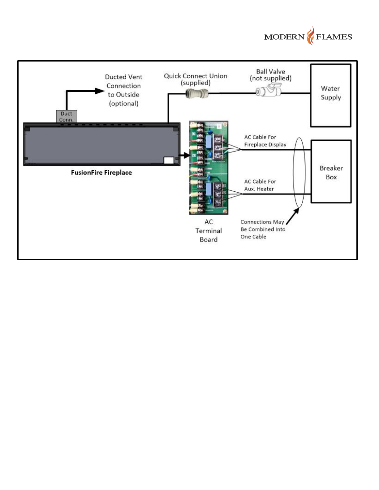
Figure 7
Page | 9
Page 10
3.3.1 Framing for Wall Build-In
Model
Height
Width
Depth
FusionFire
32”
74 1/4”
14”
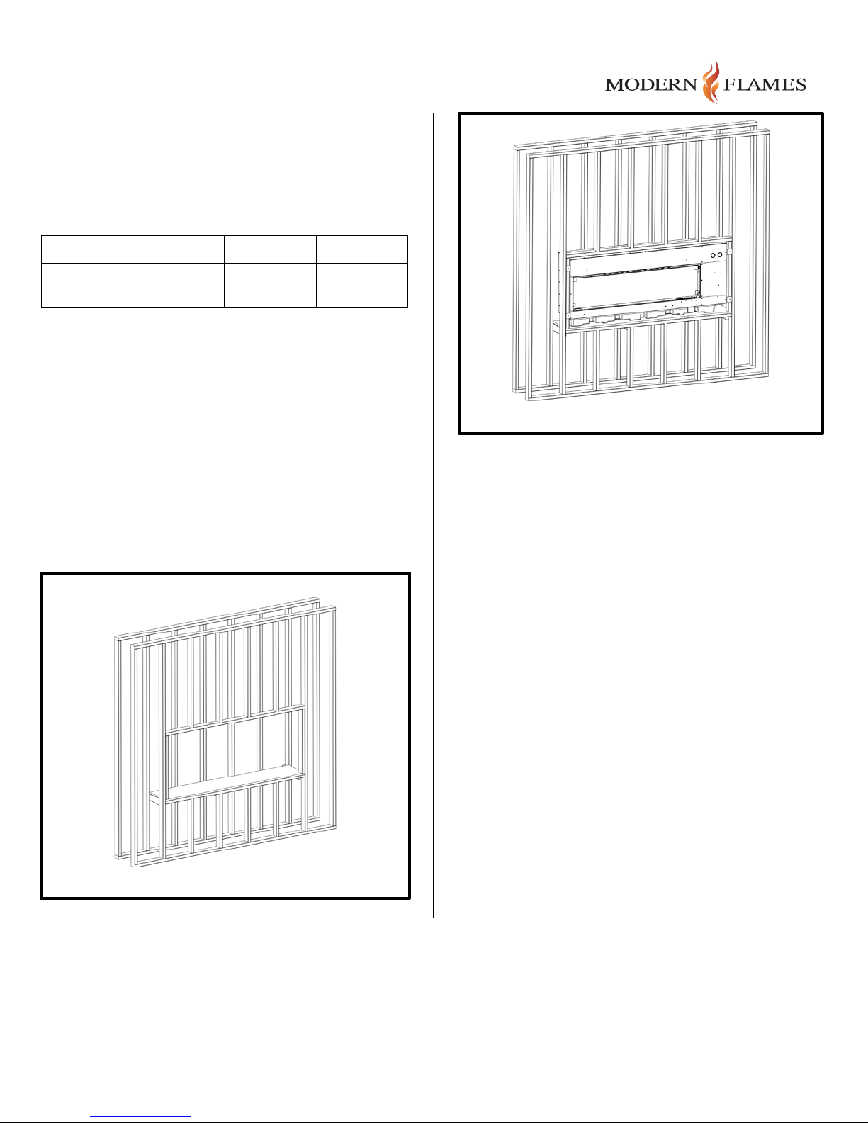
Prepare the framed opening according to the table
and figures below. Note that the opening must be
deep enough to support the 14” depth of the
fireplace assembly without touching an obstruction.
60
3.3.1.1 Framing Details
Please reference the Display Window Centerline
drawing (Figure 6 above) and the Installed Fireplace
Illustrations (Figures 8 & 9), to be sure the fireplace
is properly centered in the room.
NOTE: The fireplace becomes heavy when its water
reservoir is full. To prevent undue stress on the
framing, use a platform constructed from ¾ ” plywood
to support the entire assembly before finishing. For
best performance, this platform should be level to
within 1/16” across the width of the unit.
Figure 9
Figure 8
Page | 10
Page 11
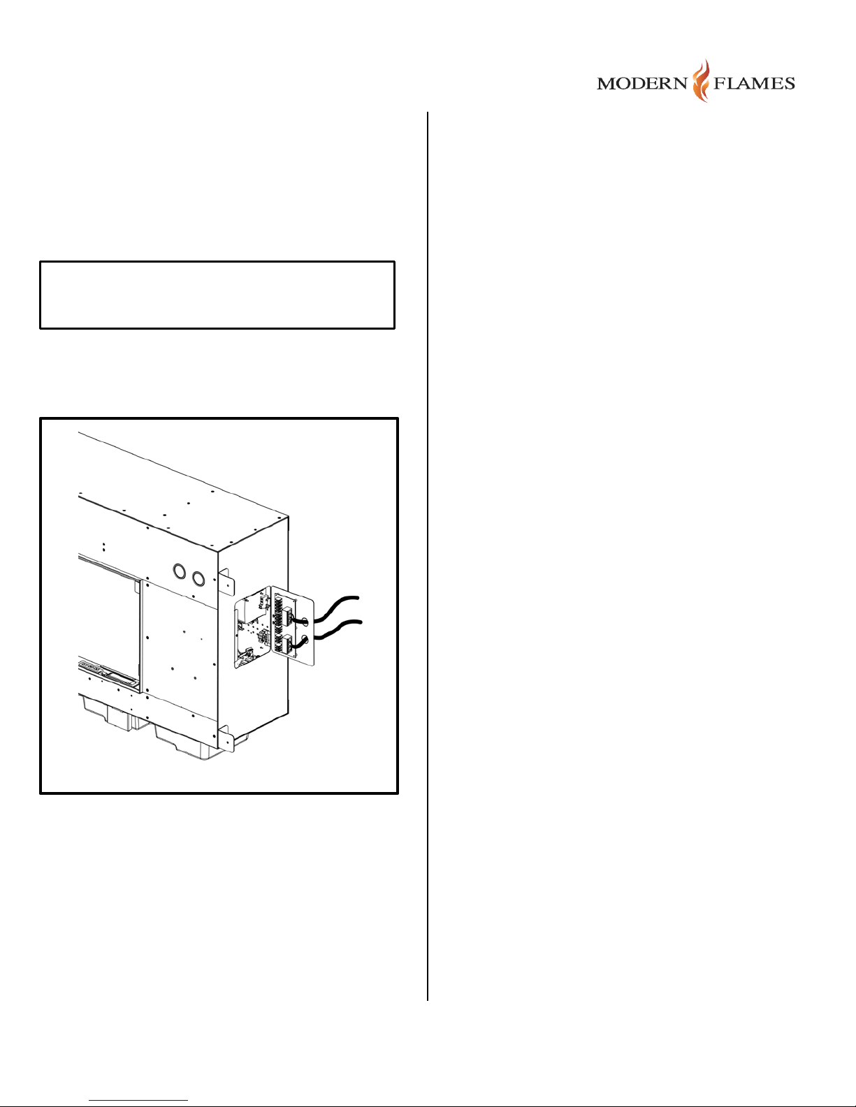
3.3.2 Electrical Power Connections
Figure 10
Small wall plug-in convertor power sources must
NOT be used to power the fireplace because of this
fireplace’s higher power requirements. Even under
the best of conditions, it is only possible to power the
system using a dedicated line back to the breaker
box; do not connect to other equipment or out lets
located in the room.
WARNING – WIRE DIRECTLY TO A
DEDICATED 20A BREAKER
The information below describes how the main
electrical connections must be setup when using the
“Flame Only” function or when using both the flame
and heater functions (Figure 10).
W/G” or 1 run of “Solid Romex 12/4 CU NM-B W/G”
cable recommended).
3.3.3 Water Supply
3.3.3.1 Water purity
A Reverse Osmosis ( R . O.) system is required for
commercial installations. Boiler life is extended
when the water supply contains low amounts of
dissolved solids. For residential applications, an RO
system is not required, but recommended for
extended boiler life.
3.3.3.2 Water line connection
When connecting to a fresh water supply, use a ¼”
polyurethane water line with a John Guest fitting
connected to an in-line ball valve.
3.3.3.3 Manual fill option
A water line is not mandatory for operation. Manual
fill is available and comes standard with each
fireplace. When the water supply container level
gets low, a warning is shown on the display to
remind the user to refill the container.
3.3.2.1 Connect: Flame Only (No Heater)
A single 120 Volt, 20 Amp power connection, which
is a dedicated line back to the breaker box (one run
of “Solid Romex 12/2 CU NM-B W/G” cable
recommended), is used to connect the main power
directly to the fireplace when only the simulated
flame is needed.
3.3.2.2 Connect: Flame & Heater
Two 120 Volt 20 Amp, dedicated lines back to the
breaker box (2 runs of “Solid Romex 12/2 CU NM-B
Although not required, using a Reverse Osmosis
(R.O.) or distilled water source to refill the water
supply is highly recommended for extended life.
3.3.4 Venting
3.3.4.1 Optional venting requirements
Please refer to Figure 11 for the location of the vent
and the vent slider control. Note that a 6” vent duct
is recommended in installations in a room that has
an area of less than 500 square feet.
Note: When using the heater, the external vent
should NOT be used. This will prevent heat from
escaping to the outside.
To prepare the vent connection, remove the
protective plate from the top of the f ireplace and
install the Vent Duct Flange in its place to use for the
duct connection.
A length of venting duct and the Vent Duct Flange, to
which is attached, are included with the fireplace
Accessory Kit (sold separately). The length of this
duct is 20 feet and is the MAXIMUM length of duct
that can be used. Using a longer length duct run will
result in improper ventilation of steam during
operation.
Page | 11
Page 12
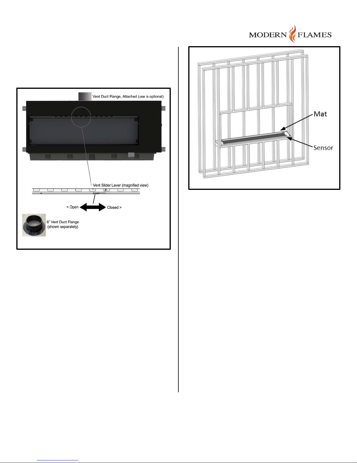
Make sure the steam vent slider lever (shown in
Figure 12
Figure 11) on the front panel is in the closed position.
This will cause the internal fan to force the steam out
via the vent rather than the front of the fireplace.
After removing the sensor from the bag, slide it into
the small slot located on the front right corner of the
mat. Be sure the two connecting wires are facing up
to allow connection to the fireplace and face the
printed circuit pattern down.
Figure 11
3.3.4.2 Steam safety
Because pure steam contains no chemicals or
breathing hazards, it is safe to operate without an
external vent. The only concerns are in situations
where there is high ambient humidity or small room
installations where humidity may build up to
uncomfortable levels.
3.4 Installation
3.4.1 Mat and Water Leak Sensor
Before installing the fireplace in the wall opening,
place the mat (Figure 12) on th e heavy plywood
bottom support. Then, locate the Water Leak Sensor
which is attached to the rear of the fireplace in a
small plastic bag.
If the sensor gets wet, it will trigg e r a Fault Code to
indicate water is accumulating in the mat.
3.4.2 Fitting the Fireplace
Install the fire unit in the framed opening while noting
the width dimension illustrated in Figure 13. This
shows the entire width, including the Fastening Tabs.
3.4.2.1 Fastening Tabs
Use drywall screws with a minimum length of 1¼” to
secure the unit to the framed opening using the Lshaped metal fastening tabs attached to the sides of
the fireplace.
Page | 12
Page 13
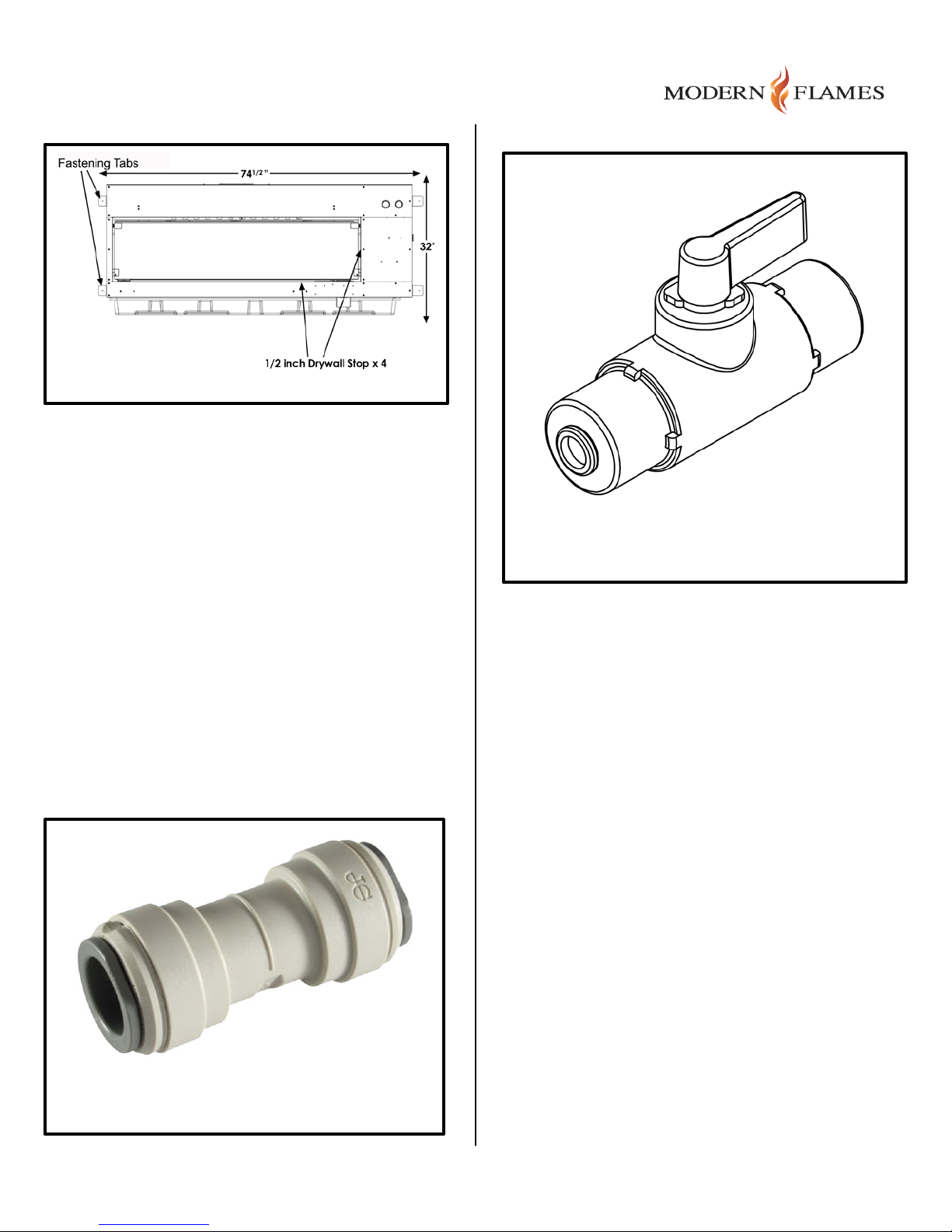
Figure 13
3.4.3 Connecting the Fireplace
Connect to water and electrical sources using the
types of connections described below.
3.4.3.1 Water Connections
Cold Water Inlet Connection: For the auto-fill
option, use the 12”-18” long, ¼” diameter poly tubing
stub-out that is packed in a plastic bag and taped to
the rear panel of the unit. It is recommended that
this tubing be joined to the water feed line by using a
John Guest, ¼”, quick connect union (supplied) as
shown in Figure 14.
It is also recommended that a compression fitting
with a shut-off valve be fitted at the water source (a
ball valve of the type shown in the Figure 15, not
supplied).
Note: There is another water shut-off valve that is
accessible through the front of the fireplace under
the media panel.
Figure 15
(Ball valve w/Comp. fittings, not supplied)
Figure 14
(John Guest quick Conn., supplied)
Page | 13
Page 14
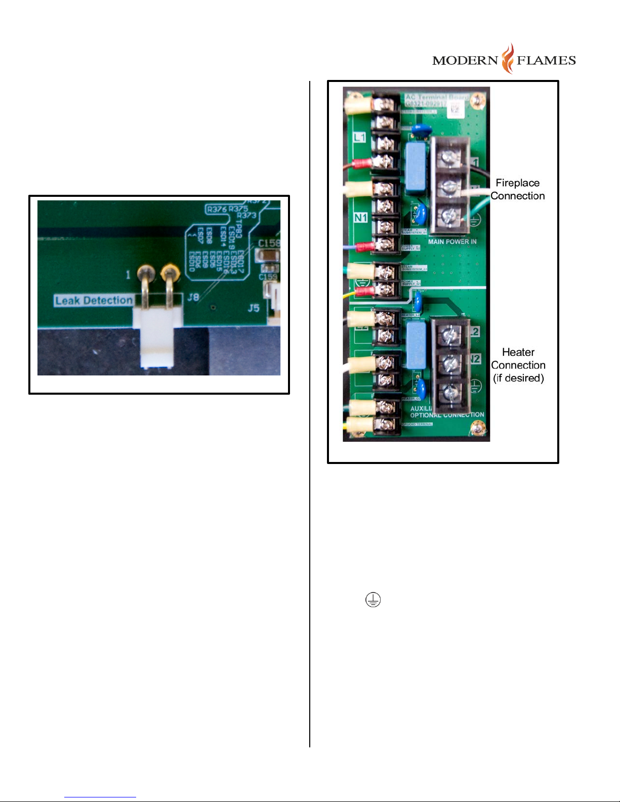
3.4.3.2 Making Electrical Connections
Figure 16
Water Leak Sensor: Connect the wire from the
water leak sensor, that was previously attached to
the rubber mat, and route it to the control board.
Plug the connector on the end of the wire into the
Leak Detection connector (Figure 16) on the control
board.
AC Wire Entry: The firebox enclosure includes 2
standard 1/2" knockouts as the entry point for
external AC wiring.
AC Connection Termination: A screw-type terminal
block is provided for connections back to the AC
breaker panel. The terminal block (see Figure 17)
accommodates the 12-gauge (L1, L2 and Gnd.)
connections for both the flame and heater.
AC wiring from the circuit breaker to the fireplace
must be “Solid Romex 12/2 CU NM-B W/G” or “Solid
Romex 12/4 CU NM-B W/G” cable.
Figure 17
AC Circuit Breakers: The AC breaker panel circuit
protection is required to be 20A single-pole circuit
breaker (15A not allowed). The auxiliary heater must
be on a separate dedicated breaker.
Terminating AC Connections: Once the wiring has
been run between the breaker panel and the
fireplace, terminate (see Figure 17 above) the
appropriate conductors at each end using
recognized line (L1, L2), neutral (N1, N2), and safety
ground standards.
3.4.3.3 Verifying Electrical Connections
With the fireplace & heater (if applicable) turned off
(power button has not been pressed) and the main
breaker in the ON position, check the open-circuit
voltage on the fireplace connection terminals and on
the heater connection terminals (if applicable).
Both open-circuit readings should read greater than
or equal to 115 Volts AC. Then, Cut the Power at
the breaker panel.
Page | 14
Page 15
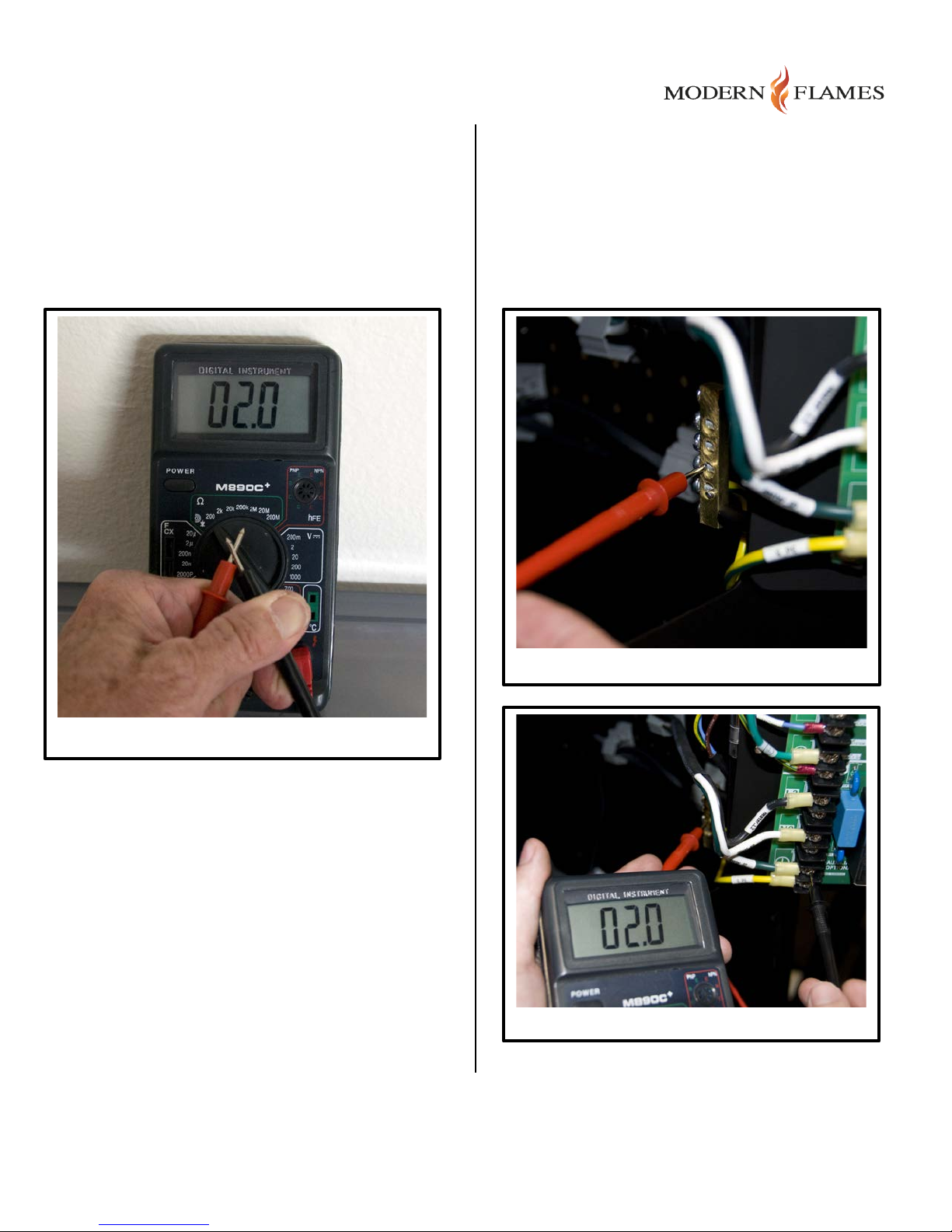
Verifying Ground Connections: Use a multimeter
Figure 19a (Ground Bar)
Figure 19b (AC Input Terminal)
to verify that fireplace metal surfaces are properly
grounded using the following procedure:
1. With the multimeter set to read Ohms on the
lowest range, short the probes together and
verify a reference reading for “0 Ohms” (or a
very low value) as shown in Figure 18.
2. Connect the multimeter between the copper
grounding bar and the green wire connection on
the fireplace’s AC input screw terminal as shown
in Figures 19a and 19b. Verify that the reading
is 0 Ohms (within 0.1 Ohms of the reference
value previously noted).
Figure 18
Page | 15
Page 16
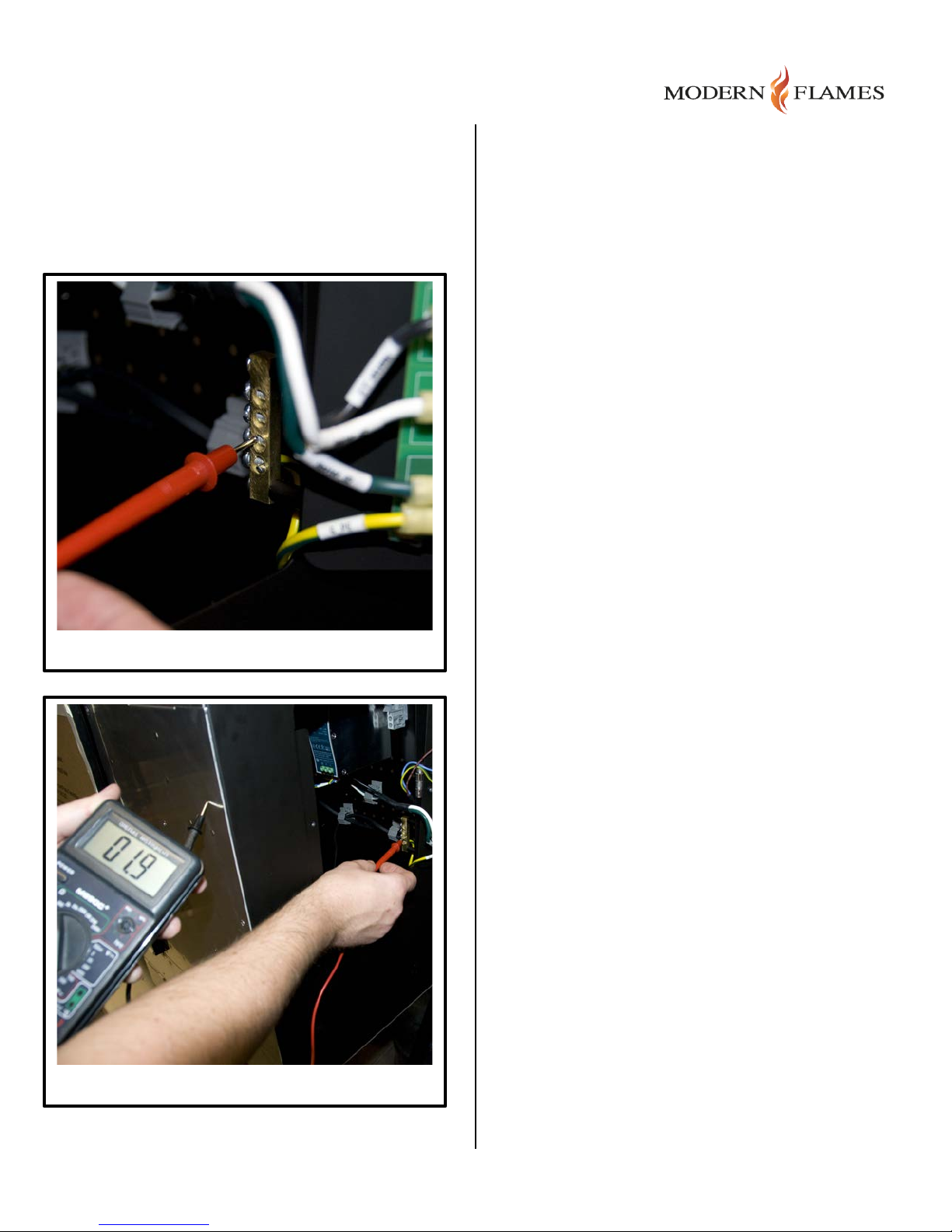
3. Connect the multimeter between the copper
Figure 20a (Ground Bar)
grounding bar and the metal portion of the
fireplace’s front panel as shown in Figures 20a
and 20b. Verify that the reading is 0 Ohms
(within 0.1 Ohms of the reference value
previously noted).
4. Likewise, connect the multimeter alternatively
between the copper grounding bar and the side
metal, rear metal, light-bar, and boiler metal
parts of the fireplace. Verify that the readings
are within 0.1 Ohms of the refer ence value for
each test.
If any of the reference readings are 0.2 Ohms or
greater, contact a factory representative before
completing the installation.
Figure 20b (Front Panel Metal)
Page | 16
Page 17
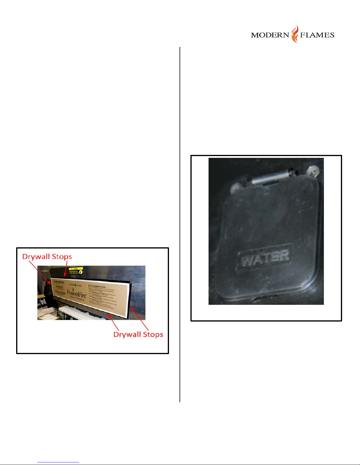
3.4.4 Finishing the wall
Figure 21
Make sure the protective cardboard and the
protective film are in place before completing the
drywall installation. It is important that drywall
finishing debris and overspray does not get applied
to the fireplace surfaces or interior components.
3.4.4.1 Drywall Stops
Install drywall to the drywall stops along the
perimeter of the fireplace display insert (see Figure
21).
3.4.5 Final start-up procedure
Make sure all connections and the fireplace itself
have been thoroughly cleared of dust and debris
before beginning the start-up procedure.
3.4.5.1 Filling the Reservoir
If using the manual water fill method, proceed as
follows: With the glass door open, lift the water fill
flap located on the left side of the media bed (see
Figure 22) and add about 3 gallons of clean water to
the reservoir. Do not fill beyond the max fill indicator.
NOTE: DO NOT DRILL OR SCREW INTO THE
FIREPLACE CHASSIS.
3.4.4.2 Drywall Placement
To secure the drywall, use a small amount of
construction strength adhesive to bond the drywall to
the front panel surface.
Make sure that the drywall does not go past the
drywall stop.
3.4.4.3 Construction Barrier
After the fireplace is installed, the drywall is finished,
construction is complete, and there is no debris on
the site, remove the cardboard construction barrier
from the front (see Figure 21).
The display will indicate each time more water is
needed.
Figure 22
Then carefully remove the protective film from the
media bed by removing the tape holding it in place.
Page | 17
Page 18
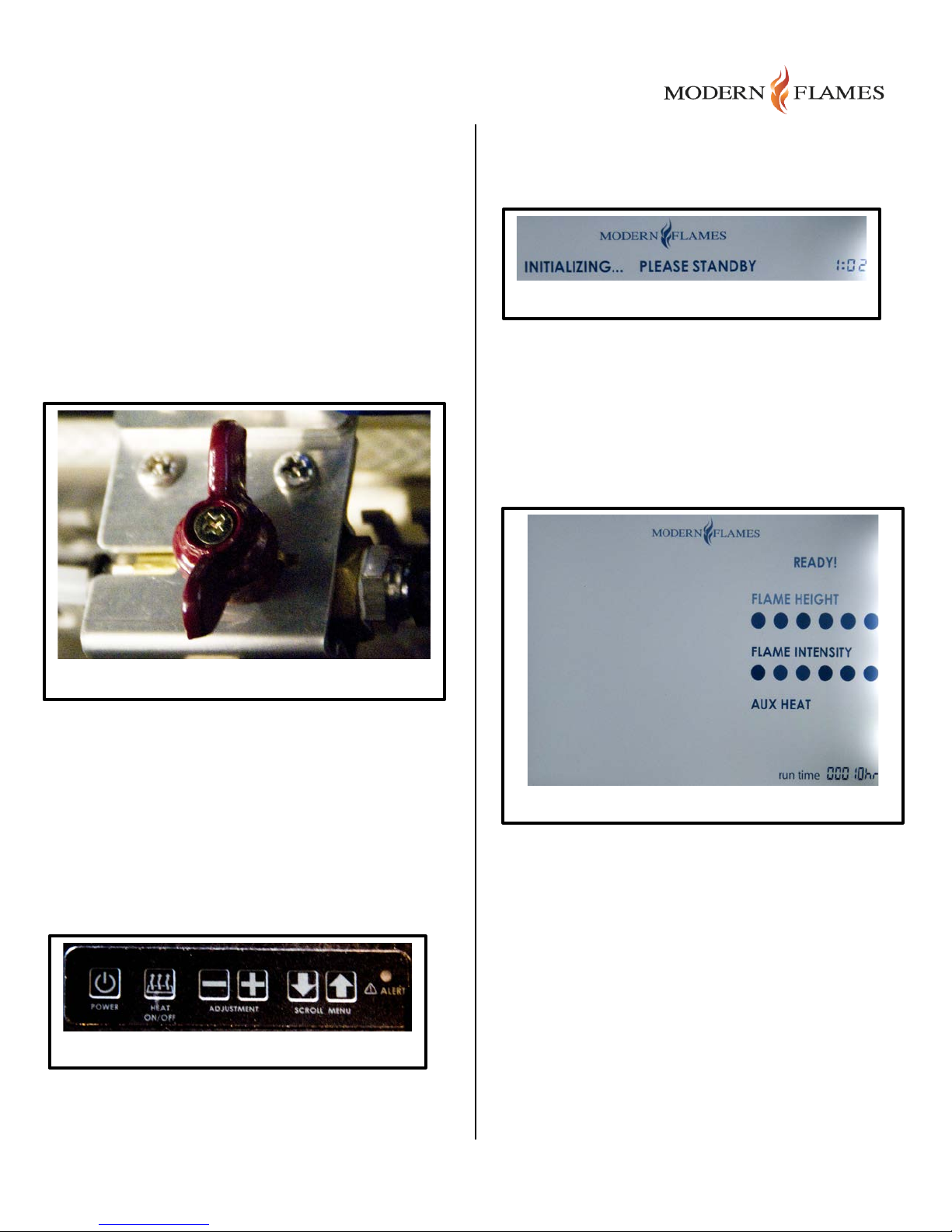
If using the direct water facilities connection option
Figure 24
Figure 26
Figure 25
(recommended), connect the water supply and
correct possible leaks before going any further.
Once a good water connection has been verified,
turn ON the ball valve (see Figure 23), shown in OFF
position) and monitor the flow into the reservoir.
A countdown timer displays time remaining while it
warms up.
Once the reservoir is full, the float valve will turn off
the flow automatically. Check again for leaks.
Place the black metal media bed into position and
screw i nto place (4 screws).
Activate the AC power by turning ON the appropriate
breaker(s) at the power panel.
Figure 23
As soon as the fireplace is ready to operate (after
about 3 minutes), you will see a “Ready” display (see
Figure 26) along with the total run time that has been
accumulated for the fireplace. After a short delay, the
simulated fire will start and the display backlight will
turn off.
3.4.5.2 Power Up
The User Display is mounted in a mechanical
“carriage mechanism”. Push the mechanism down to
release and allow viewing of the display. Push it
down again to latch and hide the display from view
(the normal operation position).
At the fireplace, with the display in the viewing
position, press the power button on the left end of
the built-in keypad (see Figure 24) to start the
fireplace.
It will begin in Warm Up mode, the text “Initializing…
Please Standby” (shown in Figure 25) is displayed.
If a problem occurs during startup, an alert condition
will be indicated in the display area. For more details
about this refer to the “Servicing” section.
Checking the AC Load Current: Using an AC Amp
Meter monitoring the hot side (black) branch circuit
connection to the fireplace at the breaker box,
measure the AC load current (see Figure 27). With
the boiler still heating, it should be 16 Amps or less.
NOTE: If t he boiler has reached operating
temperature and has cycled off, wait for it to cycle
back ON and take the AC current reading again.
If the optional heater is equipped, likewise measure
the AC current probe to the hot side (black) branch
Page | 18
Page 19
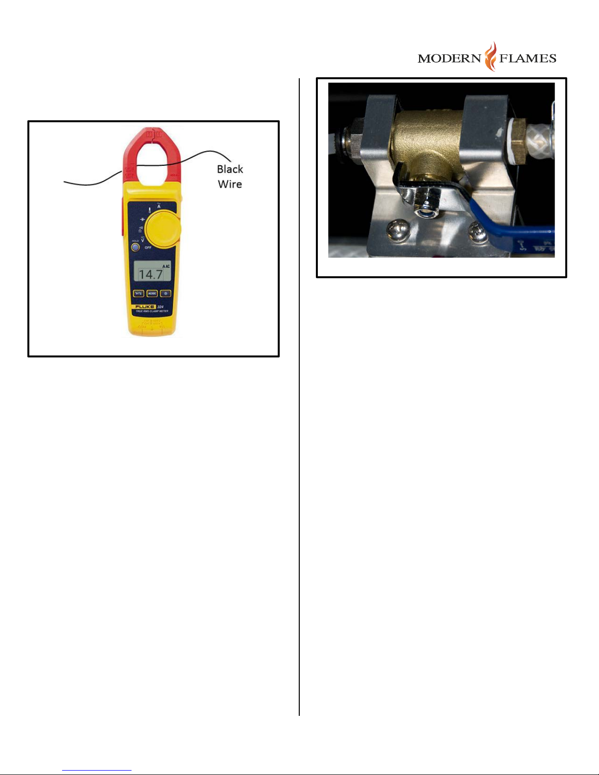
circuit connection to the heater, turn the heater on,
Figure 27
and verify that the current draw on that circuit is 16
Amps or less.
Figure 28
3.4.5.3 Fire Bed Media Installation
The Fireplace package includes a 10 Lb. bag of
decorative glass media. Optional media can be
selected by the user and separately placed by the
installer.
The media must be evenly distributed over the
bottom metal panel that covers the water reservoir.
This it done to maximize the fire ember effect when
the lighting is active during operation.
3.4.5.4 Draining the Reservoir/Boiler
Should it become necessary to drain the boiler and
reservoir, a T-valve is positioned in the water line
between the Steam Subsystem pump and the
manifold inlet. A “recoil” type drain hose of length 2m
+/- .5m is connected to the T valve and stored for
use beneath the media bed.
To drain the water tank for winterizing, the T-valve
(see Figure 28) is used to route water from the pump
out the drain hose. One end of the drain hose is
pulled out of the fireplace and placed into an external
bucket. The pump is activated during system power
ON by pressing and holding both “up/down” AdjustButtons on the keypad simultaneously.
Page | 19
Page 20

3.5 Installation FAQ’s
FREQUENTLY ASKED Q UESTIONS
Q. How do you program the remote control?
A. The remot e comes pre-programmed and ready to use. No programming is necessary.
Q. What distance can the remote be used from the fireplace?
A. Optimal distance for the remote control is within 16 feet (5 meters).
Q. Can you turn on the fireplace via the front panel keypad and off via the remote (or vice
versa)?
A. Yes.
Q. How long will the LED lights last?
A. LED Lamps have a life span of up to 20 years.
Q. Can the fireplace be installed outside?
A. No. Please review the entire safety sections before installing this fireplace.
Q. Does the fireplace need to be on a dedicated 20 Amp circuit?
A. Yes, and two dedicated 20 Amp circuits must be wired when the heater is used.
Q. What thickness of drywall should be used for the recessed installation?
A. 1/2” or 5/8”.
Q. How often does the battery in the remote need to be replaced?
A. Annually, possibly more with heavy use.
Q. Is there a remote receiver in the fireplace that requires a battery?
A. No, only the actual remote requires a battery. The rest of the fireplace runs entirely off of the
main power supply.
Page | 20
Page 21

3.6 Troubleshooting
PROBLEM
POSSIBLE CAUSE
CORRECTIVE ACTION
Wiring is loose at fireplace
Shutoff the breaker at the
Breaker panel connection is
Shutoff the breaker, check the
Boiler connections are loose
Disconnect from power source
Boiler control board is defective
Replace the control board with
There is a problem with the
Reposition the fireplace in the
Power was “live” when the
Turn the main breaker to the
Not operating the keypad
Press the end of your finger
Loose connection on control
Check functions with remote
Fault code 07 “BOILER OVER
Refill boiler or repair water
Follow the procedures outlined below to diagnose and resolve problems. Note: Always remove
power from the system at the breaker box before replacing electrical components. To restart
the system, turn OFF the power at the beaker box for 30 seconds and then restore.
3.6.1 Fault Diagnosis Chart
Flame and backlight are
not visible but fireplace
display shows it’s turned
on
Fireplace lights up but
there is no flame visible
Nothing comes on (front
panel screen, etc.)
loose or breaker is defective
keypad and/or its mounting that
is preventing the buttons from
functioning
fireplace was installed
breaker panel and check the
connections
breaker panel connections,
verify voltages, and
tighten/replace as needed.
and inspect for loose
connections between the
boiler and its control board
one of the same model and
part #
installation so that no part of
the fireplace is interfering with
the keypad controls. Check
that there is no foreign
material lodged in the keypad
"OFF" position for 30 seconds.
Next flip the breaker back into
the "on" position for 20
seconds for a complete reboot
of control section.
Fireplace turns off on its
own and will not come
properly with finger
board
TEMPERATURE” is shown on
the display
firmly on the keypad and apply
moderate pressure
control. if functional, check
wiring connections on control
board
supply access.
Page | 21
Page 22

back on and display
Fault code 15 “ROOM
Remove built up dust from the
Fault code 15 “ROOM
Check the ambient room
Low Battery
Replace battery in remote
Not aiming control correctly
Aim remote control to the
Remote control defective
Replace remote control
Remote Sensor is defective
Replace remote sensor inside
Heater wiring is loose at
Shutoff the breaker at the
Breaker panel connection is
Shutoff the breaker, check the
shows a Fault message
Keypad operates the
fireplace but the remote
control does not
Aux heater does not
function and/or Fault
code 16 “AUX HEATER
FAILURE” is shown on
the display
TEMPERATURE ABNORMAL”
is shown on the display
TEMPERATURE ABNORMAL”
is shown on the display
fireplace
loose or breaker is defective
fireplace vents and replace
internal fan if necessary.
temperature and make
changes to maintain it
between 65F-85F.
control with a 2032 coin-cell
upper right of the viewing area
where sensor is located
fireplace
breaker panel and check the
connections
breaker panel connections,
verify voltages, and
tighten/replace as needed.
Page | 22
 Loading...