

Modern Flames AL 38, AL 56, AL 95 Installation Instructions Manual

Ambiance Wall Hung Electric Fires
Packing Check List
Package 1 1 x Electric Fire
1 x Glass Face
1 x Remote Control Handset
2 x AAA Batteries
1 x Instructions Booklet
1 x Wall Fixing Plate
1 x Fasteners Package
Package 2 1 x Fire Face (Stone Face Models only)
INSTRUCTION BOOKLET MUST BE LEFT WITH THE USER

2
Ambiance Wall Hung Electric Fires
INSTALLATION INSTRUCTIONS
This Electric Fire must be installed by a qualified, competent installer.
A. Location
1. The fire must not be in contact with any combustible materials.
2. The heater, which is located at the base of the fire, must be a minimum of 16
inches away from any combustible material.
3. It is important that the wall on to which the fire is to be installed is of sound
construction. All fasteners must be suitable for the type of wall, must be secure
to the wall and capable of taking the weight of the fire and the face.
4. The fire must not be installed in an area where there is restricted air flow around
the fire.
5. This appliance is for indoor installation but is ok to be installed outside in fully
covered installations free from damaging weather (rain snow etc.)
6. The appliance must be kept away from any source of damp or moist conditions.
Avoid any close contact with water.
7. If there is any doubt regarding the suitability of the installation site contact your
supplier.
8. These fires produce heat consequently it is important to ensure that a suitable
wall covering is selected behind and around the appliance. Typical wood frame
drywall construction is suitable.
3
B. Installation
PLEASE READ THROUGH THE INSTALLATION INSTRUCTIONS BEFORE
BEGINNING THE INSTALLATION.
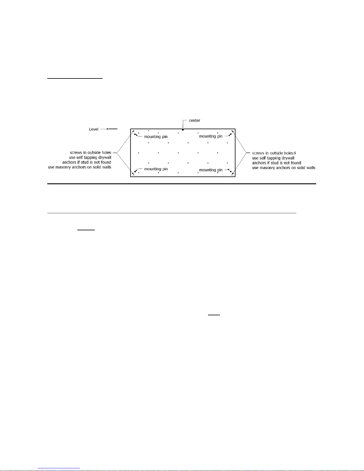
Figure 1
1. Select the position of the fire on the wall to which it is to be mounted. Draw a
level horizontal line on the wall at the required height. This line will correspond
to the top of the appliance so it is important to allow for the extra height of the
fire front.
2. Mark the center li ne of the fir e on to t he hori zontal line
3. Place the Installation Plate supplied to the horizontal line and line up the center
“V” cut out with the center line. See Figure 1.
4. DRYWALL INSTALLATION) Install screws provided into studs at 4 outside
corner screw holes. If studs are not present, install self drilling hollow wall
anchors provided at the 4 outside corners and find wood studs with at least 4
more screws on the mounting plate. (2 high and 2 low) Holes are offset to allow
finding wood studs at normal spacing. Attach more screws into wood on 95”
model.
5. MASONRY INSTALLATION) If the wall is of a sound masonry construction the
attaching holes should be drilled with an 5/16” mm masonry drill. First secure the
4 outside corners. Use the masonry anchors and screws provided. Double
check that a firm solid attachement is achieved or add additional anchors as
required.
6. If a firm attachement cannot be achieved it may be necessary to install extra
support to the framing. It is most important that the mounting plate are firm and
solid and that the structure is capable of taking the load.
4
7. The mounting plate has four location pins, one at each corner of the plate. See
Figure 1.
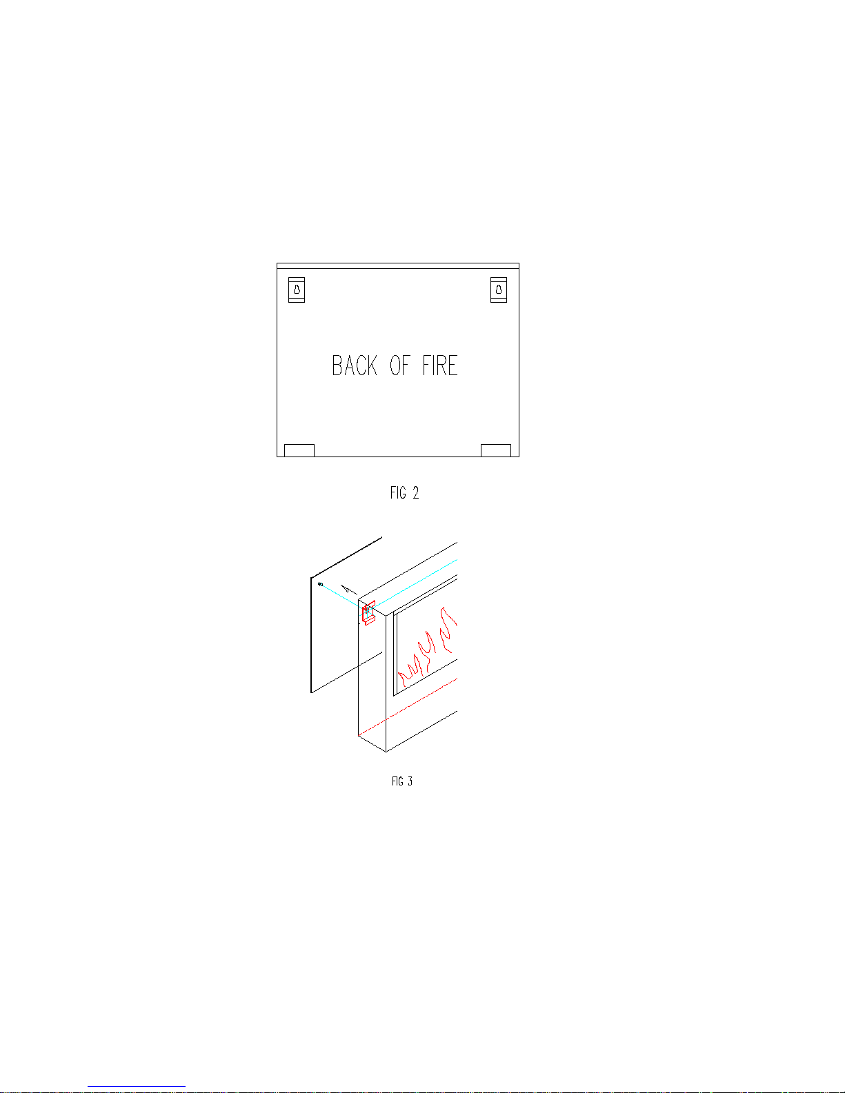
8. Lift the fire and place the keyhole slots situated on the back of the fire (Figure 2)
to the location pins on the mounting plate. A gentle downward pressure should
be applied. Make sure all of the pins have been located into the top section of
each keyhole fixing slot. (See Figures 3 & 4)
 Loading...