

Modern Fan Co Velo DC VEL, IC/Air3 DC, IC3 Owner's Manual

A note about our
online installation instructions:
Most Modern Fan Co. products have been in our assortment for several
years or longer. As we continually work to improve product performance
and user experience, we occasionally introduce subtle (and sometimes
dynamic) product changes. These can affect the steps associated with
assembly and installation of our products depending on when a fan
was produced.
The instructions posted here are intended to represent our most current
product versions and configurations and the associated installation
steps. If your fan or parts of your fan do not appear to match what is
included here, please contact customer service for guidance and support
in identifying which version of a fan you may have and provision of the
associated installation instructions which correspond to that version.
If in doubt, or if you have any questions at all related to assembly,
installation or operation of your fan, please contact us!
709 Washington Street, Ashland, OR 97520
tel 888-588-3267, fax 541-482-8418
info@modernfan.com
modernfan.com
Velo DC
Installation Instructions
and Owners Manual
Models: VEL–XX–XX–XX–XX(X)–XX
Net Weight of Fan: 14.0 lbs (6.4 kgs)
Please read and save
these instructions.
If you have any
questions while
installing your fan,
call us first!
Safety Instructions and Warnings .....2
Fan Installation ..........................................4
Control Installation and Wiring ..........7
Troubleshooting ......................................12
Maintenance ............................................ 14
Warranty ......................................................15
Customer Service
Monday–Friday, 8am–4pm (PST)
tel 888-588-3267
Safety Instructions and Warnings
Please read all safety instructions prior to installing your ceiling fan
and save this document for future reference. If you are in doubt with
any of the information provided, we recommend that you consult
or hire a qualified electrician to install your outlet box and ceiling fan.
If you have any questions or difficulty installing your fan,
call Modern Fan Co customer service at (888) 588-3267.
Circuit Breaker
WARNING
Warning – To reduce the risk of fire, electrical shock, or personal
injury please observe the following:
Mount fan to outlet box marked “Acceptable for Fan Support” and use
mounting screws provided with the outlet box. Note: Most outlet boxes
commonly used for light fixtures are not acceptable for fan support and may
need to be replaced. Consult a qualified electrician if in doubt.
Prior to installation or servicing always disconnect the power by turning off the
circuit breakers to the outlet box and associated wall switch location. If you
cannot lock the circuit breaker in the off position, securely fasten a prominent
warning device, such as a tag, to the service panel.
Do not bend the blade brackets when installing the blades, balancing the
blades, or cleaning the fan. Do not insert foreign objects in between
rotating fan blades.
Disconnect the electrical supply circuit to the fan before installing light kit.
Do not use this fan with any solid-state speed control device other than one
provided or approved by the manufacturer.
This fan must be installed with an isolating wall control/switch.
All wiring must be in accordance with national and local electrical codes
ANSI/NFPA 70. If you are unfamiliar with wiring, use a qualified electrician.
Use this unit only in the manner intended by the manufacturer. If you have
any questions contact the Modern Fan Co at (888) 588-3267.
Use only Modern Fan Co replacement parts.
POWER OFF
Note: This fan is rated and marked as “Suitable for use in Damp Locations.” This
fan is suitable for installation in interior locations protected from weather and subject
to moderate degrees of moisture, such as some basements, barns, cold storage
warehouses, and similar locations, and also partially protected locations such as under
canopies, marquees, roofed open porches, and similar locations. This is not rated,
nor intended for use in applications classified as Wet Locations.
2
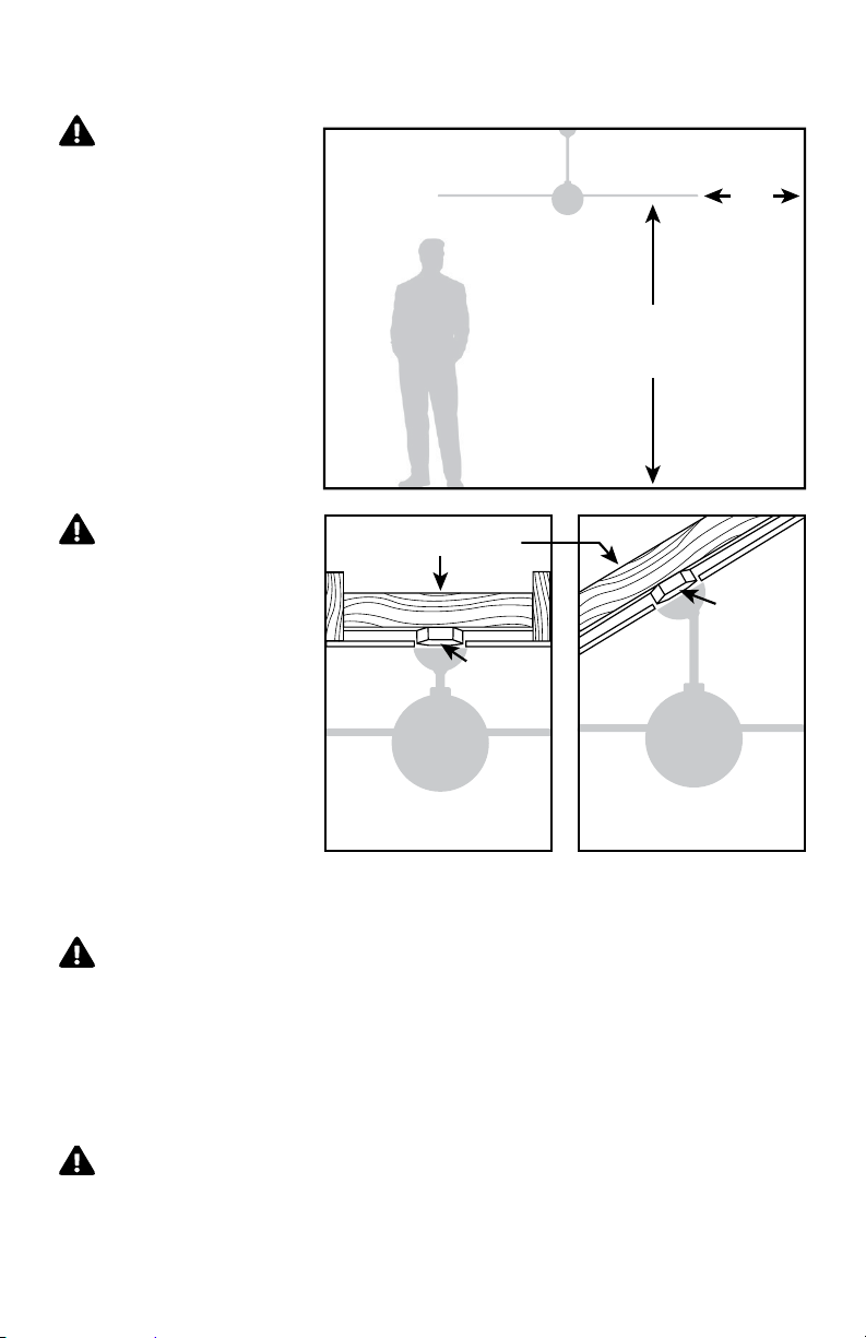
Installation Preparation
WARNING
Make sure the installation
site you choose allows the
fan blades to rotate without
any obstruction. Allow a
minimum clearance of 7 feet
(2.1 meters) from the floor
to the blades and 30 inches
(76 cm) from the wall to the
end of the blades.
WARNING
Your new ceiling fan
will require a grounded
electrical supply line of
120 volts AC, 60 Hz,
15 amp circuit. The outlet
box must be securely
anchored and capable of
withstanding a load of
35 lbs (15.9 ww kg).
Fan Location
Support Structure
Ceiling
Outlet Box
(required)
30 inches (76 cm)
Minimum of
Minimum of
7 feet (2.1m)
Ceiling
Outlet Box
(required)
Flat Ceiling Mount Angled Ceiling Mount
Control Installation and Wiring
If you are using an outlet box for wall control installation, the
WARNING
wires coming from the wall control must be grounded using the attached green wire.
After making wire connections, the wires should be spread apart with the grounded
conductor and the equipment-grounding conductor on one side of the outlet box and
the ungrounded conductor on the other side of the outlet box.
The splices after being made should be turned upward and pushed carefully up
into the outlet box.
This device complies with Part 15 of the FCC Rules. Operation
WARNING
is subject to the following conditions: (1) the device may not cause harmful interference,
and (2) this device must accept any interference received, including interference that
may cause undesired operation.
3
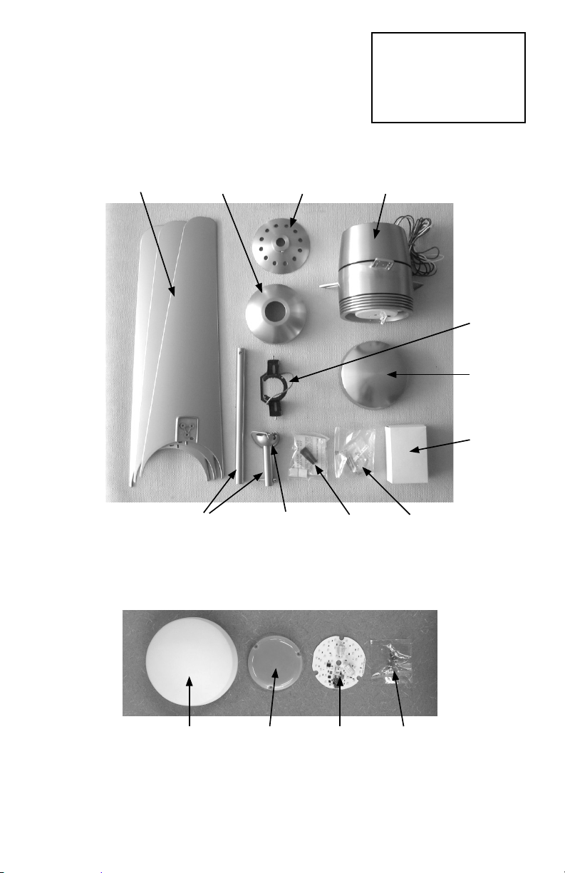
Fan Installation
Instructions
Remove and identify contents of carton.
1
blades canopy top cover fan body
Tools Needed
A stepladder, phillips
head screwdriver and a
wire stripper
hanging
bracket
bottom
cap
control(s)
may
include 2
or 3 pieces
down rods half-ball balancing
kit
hardware
package
Optional Light Kit parts:
glass
diffuser
4
isolation
cover
LED
board
screw
pack
See Page 2
WARNING
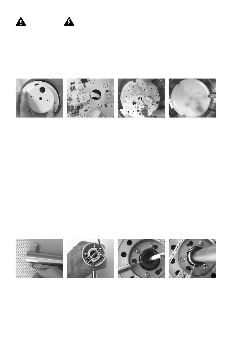
If your fan was ordered with the optional LED light, it should be pre-installed.
2
However, if the LED components are not installed, begin by removing the
bottom mounting cup. Route 2-pin connector through center hole on LED
board and carefully insert into terminal. Position isolation cover over LED board
and align holes with holes on fan body. Secure cover and LED board to fan.
Circuit Breaker
POWER OFF
remove
mounting cup
Remove stopper pin, cottor pin and washer from end of 4.5” down rod assembly
3
and set aside for reinstallation. Remove half-ball from 4.5” down rod by loosening
set screw and removing stopper pin, also setting aside all parts for re-installation.
Carefully place fan body in upright position in a manner so as to avoid damage
to the light kit lead wires or the LED cover on the underside of the fan. Slightly
loosen two set screws on down rod coupler. Run lead wires from fan body through
selected down rod and fit down rod into coupler, taking care not to pinch or
damage wires. Align holes in down rod with hole in coupler and reinstall stopper
pin, cotter pin and washer assembly. Firmly and evenly tighten tighten set screws
against down rod.
Note: If ceiling height allows, a longer down rod will improve air flow performance.
However, blades must be at least 7 feet above the floor.
remove stopper
pin, cotter pin and
washer
2-pin connector
remove half-ball
and stopper pin
align board
with holes
loosen set screws
on coupler
install down rod
with stopper pin
assembly and
tighen set screws
secure cover
and board
5
 Loading...