

Modern Fan Co Eclipse Installation Instructions Manual
MODERN FAN COMPANY
Customer Service
M-F 8am - 4pm (PST)
(ph) 888.588.3267
www.modernfan.com
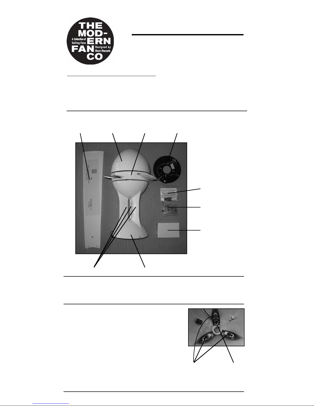
(1) Remove and identify contents of carton.
Eclipse Fan- Installation instructions
Should you have any questions or difficulty installing your new fan,
please contact Modern Fan Co. customer service immediately.
Note: Power supply must be turned off prior to any contact with electrical wires.
It is recommended that a licensed electrician be hired to install your ceiling fan.
Eclipse
optional control
balancing kit
mounting plate
blades
canopy
hardware
package
bottom dome
down rods
rotor
(3) If using optional, longer down rods,
dismantle standard down rod assembly:
(a) loosen three nuts from threaded rods
(b) remove and set aside nuts and washers
(c) remove canopy and outer down rods
(d) remove (unscrew) threaded rods from
fan body
(e) install replacement down rods by
following steps (a) through (d) in reverse
- Lead wires will need to be run through
down rod and wire chase accordingy.
(2) The Eclipse fan requires a slope ceiling adapter if installed on a sloped, or
pitched, ceiling (Part # SAE-GW or #SAE-BA). Please refer to instructions
packaged with “Eclipse Slope Ceiling Adapter”.
nuts, washers &
threaded rods
wire
chase

(5) Secure suspension cable loop (from mounting
plate) around hook inside the canopy at top of fan.
(4) Using the existing screws from your junction box,
or the machine screws from the hardware package,
secure the ceiling plate to ceiling junction box. The
electrical wire must be accessible through the hole in
the center of the ceiling plate.
(6) Lift fan body and carefully align canopy with
ceiling plate. Tabs on ceiling plate should seat into
channel on inside of fan canopy. Rotate fan so that
set screw holes on fan body align with set screw
holes on ceiling plate.
hook
With fan suspended by cable, make wire connections
with wire nuts included in hardware package as
described in the control installation instructions. If
using the optional #003 or #004 control, the
receiving unit should be placed inside the top of the
fan and connected at this time.
set screw hole
(8) Remove and set aside bottom dome by rotating
counter-clockwise.
(9) Carefully insert blades into rotor slots, and using
screws from hardware package, secure blades to
rotor. The counter sink screws (“blade center
screws”) are for the single blade hole outside the
rotor and the pan head screws (“blade holder
screws”) are for the two holes inside the rotor area.
(10) Reinstall bottom dome by rotating in the clock
wise direction, or if installing the optional light kit,
proceed to step (12).
(7) Insert and tighten the three canopy screws
included in the hardware package.
Note- Do not tighten down set screws until all
three are partly screwed in.
canopy screw
 Loading...