

Modern Fan Co Cloud Installation Instructions Manual
THE MODERN FAN COMPANY
Customer Service
M-F 8am - 4pm (PST)
(ph) 888.588.3267
www.modernfan.com
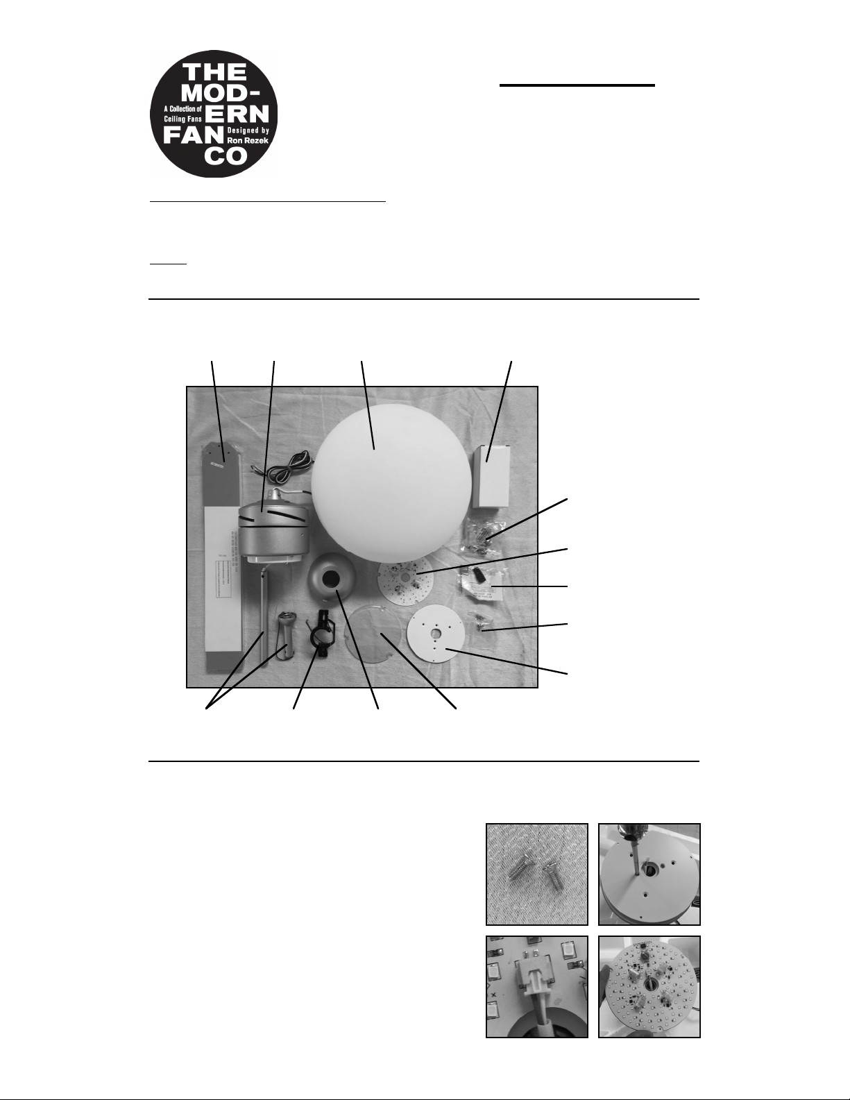
(1) Remove and identify contents of carton.
Cloud Fan- Installation instructions
Should you have any questions or difficulty installing your new fan, please contact
Modern Fan Co. customer service immediately.
Note: Power supply must be turned off prior to any contact with electrical wires. It is
recommended that a licensed electrician be hired to install your ceiling fan.
Cloud
control(s)
balancing kit
hanging
bracket
blades
fan body
hardware
package
canopy
down rods
& half-ball
glass diffuser
LED board
LED adapter
plate
LED screws
LED cover
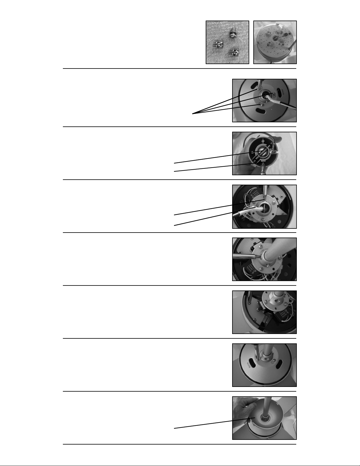
(2) Place fan body on either piece of packing foam, with wire bundle facing down and
bottom of fan facing up. Follow these steps (a) through (c) to attach LED
components to your fan:
(a) Align holes on adapter plate with holes on
switch housing. Using countersink screws
included with LED pack, secure adapter plate to
switch housing.
(b) Position and insert 2-pin connector into
terminal near center hole of LED board.
Position LED board flat on adapter plate so that
three cutouts are positioned over attachment
holes. Feed any excess wire back into switch
housing.
(6) Run fan wires through selected down rod. Reinstall
stopper screw from step (5) and firmly tighten set screw on
fan collar against down rod.
Note: If ceiling height allows, using a longer down rod will
increase airflow and efficiency.
(7) Insert one blade at at time into rotor slot, aligning with
“pie-slice” opening in black plate. Using blade screws from
hardware package, secure blade to rotor. Start all three
screws before completely tightening. Repeat for all blades.
(5) Remove the stopper screw and loosen the set screw on
the fan collar. Set the
stopper screw aside for step (6).
(3) Using packing foam to position fan body in an upright
and stable position, remove the rotor cover by loosening the
three cover screws. Set the
cover aside for reinstallation in step (8).
cover screws
(4) Remove stopper pin and half ball from small down rod
by loosening set screw on half ball. Set parts aside for
reinstallation in step (10).
stopper pin
set screw
stopper screw
set screw
(8) Making sure to align opening labeled “reverse” over the
reverse switch, reinstall rotor cover from step (3) by
tightening all three cover screws.
(9) Slide fan canopy over down rod and carefully rest on top
of fan body.
canopy
(c) Position LED cover over LED board so that
attachment holes are aligned with cutouts and
holes in adapter plate. Using three additional,
small pan head screws included with hardware
pack, secure LED cover and LED board to
adapter plate.
 Loading...