

Modern Fan Co Cirrus Installation Instructions Manual

A note about our online installation instructions:
w w w . m o d e r n f a n . c o m
fan, please contact us!
Most Modern Fan Co. products have been in our assortment for several years
or longer. As we continually work to improve product performance and user
experience, we occasionally introduce subtle (and sometimes dynamic)
product changes. These can affect the steps associated with assembly and
installation of our products depending on when a fan was produced.
The instructions posted here are intended to represent our most current product versions and
configurations and the associated installation steps. If your fan or parts of your fan do not appear to
match what is included here, please contact customer service for guidance and support in
identifying which version of a fan you may have and provision of the associated installation
instructions which correspond to that version.
If in doubt, or if you have any questions at all related to assembly, installation or operation of your
709 Washington Street • Ashland, OR 97520 • (tel) 888.588.3267 • (e) info@modernfan.com
THE MODERN FAN COMPANY
Customer Service
M-F 8am - 4pm (PST)
(ph) 888.588.3267
www.modernfan.com
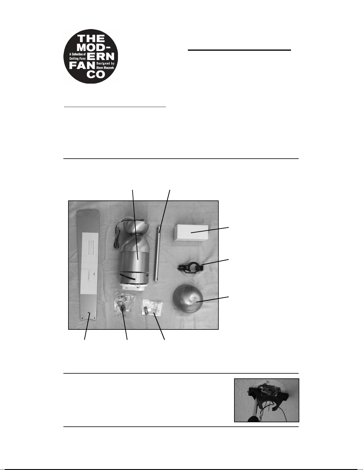
(1) Remove and identify contents of carton.
Cirrus Fan- Installation instructions
Should you have any questions or difficulty installing your new fan,
please contact Modern Fan Co. customer service immediately.
Note: Power supply must be turned off prior to any contact with electrical wires. It is
recommended that a licensed electrician be hired to install your ceiling fan.
Cirrus
control(s)
balancing kit
hanging
bracket
blades
hardware
fan body
bottom
dome
extra down rod
(2) Using the existing screws from your junction box, or the
machine screws from the hardware package, secure the
hanging bracket to the ceiling junction box.
(3) The Cirrus fan ships in a 17” long configuration. If ceiling height allows, using a
longer down rod will increase airflow and efficiency. If you would like to install a
longer down rod, follow steps (a) through (d). Otherwise, proceed to step (4).
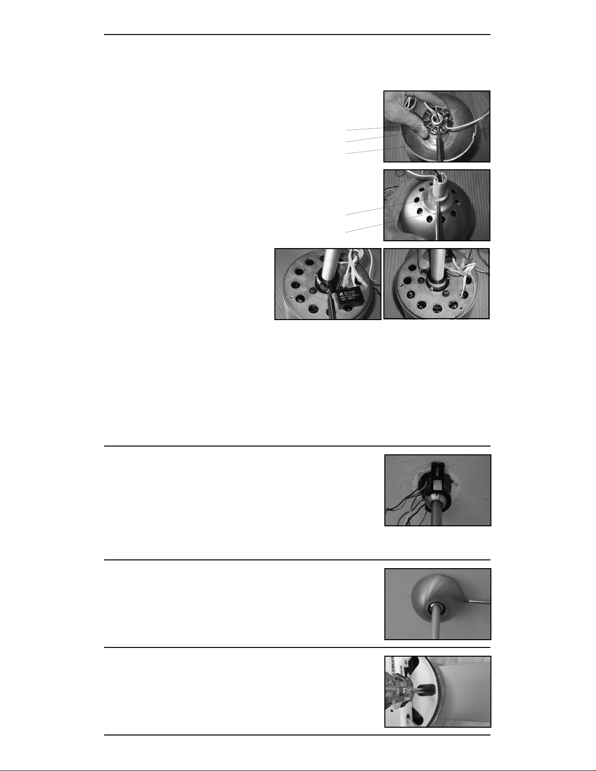
(a) Remove stopper pin and half ball from small down rod
by loosening set screw on half ball. Set these parts and
canopy aside for reinstallation.
stopper pin
set screw
canopy
(b) Remove top dome by loosening screw on fitting
against down rod, above top dome. Slide fitting and
dome up down rod and set aside for reinstallation.
fitting
top dome
(c) Slightly loosen three screws
where down rod is attached to
motor and remove the cotter pin
and through pin assembly. Set all
parts aside for reinstallation.
(d) Remove down rod and run fan wires through selected replacement down rod.
In reverse order, follow steps above to reassemble.
Note: When tightening the three screws where the down rod attaches to the motor.
take care that the down rod is centered evenly. This may require adjustment of the
three screws.
Very Important: The through pin and cotter pin assembly at the base of the down
rod and the stopper pin at the top of the down rod must be reinstalled for a safe
and secure installation of your fan.
(4) Lift fan to ceiling and set half ball in the hanging bracket
so that the ridge on the edge of the hanging bracket is
seated in the slotted channel in the half ball.
(5) Remove set screws on the sides of the
hanging bracket. Lift canopy to ceiling. With slots
on side of canopy aligned with set screws on
hanging bracket, reinstall and tighten set screws
to hold canopy in place.
With fan safely suspended by bracket, make wire connections
with wire nuts included in hardware package as described in
the control installation instructions. If using the optional #003,
#004 or #005 control, the receiving unit should be placed inside the arms of the
hanging bracket and connected now.
(6) Carefully insert blades into rotor slots, and
using pan head screws from hardware package,
secure blades to rotor. Screwdriver and screw
passes through oval holes to access blade and
rotor attachment points.
 Loading...