

Modern Fan Co Ball Installation Instructions Manual

A note about our online installation instructions:
Most Modern Fan Co. products have been in our assortment for several years
or longer. As we continually work to improve product performance and user
experience, we occasionally introduce subtle (and sometimes dynamic)
product changes. These can affect the steps associated with assembly and
installation of our products depending on when a fan was produced.
709 Washington Street • Ashland, OR 97520 • (tel) 888.588.3267 • (e) info@modernfan.com
w w w . m o d e r n f a n . c o m
The instructions posted here are intended to represent our most current product versions and
configurations and the associated installation steps. If your fan or parts of your fan do not appear to
match what is included here, please contact customer service for guidance and support in
identifying which version of a fan you may have and provision of the associated installation
instructions which correspond to that version.
If in doubt, or if you have any questions at all related to assembly, installation or operation of your
fan, please contact us!
THE MODERN FAN COMPANY
Customer Service
M-F 8am - 4pm (PST)
(ph) 888.588.3267
www.modernfan.com
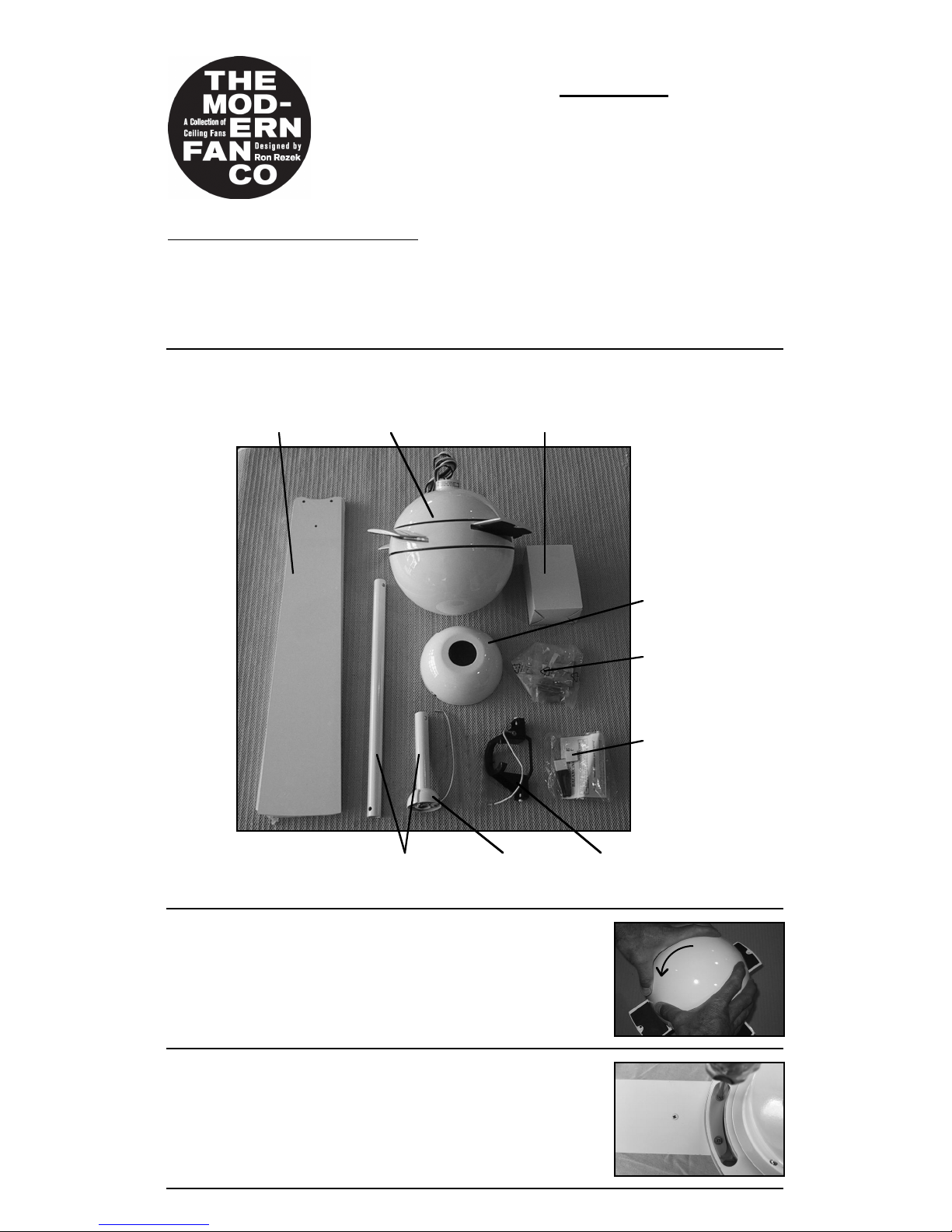
(1) Remove and identify contents of carton.
Ball Fan- Installation instructions
Should you have any questions or difficulty installing your new fan,
please contact Modern Fan Co. customer service immediately.
Note: Power supply must be turned off prior to any contact with electrical wires. It is
recommended that a licensed electrician be hired to install your ceiling fan.
Ball
optional control
balancing kit
hanging bracket
blades
canopy
hardware
package
fan body
down rods
half ball
(2) Remove bottom dome by rotating counterclockwise.
You may need to hold the upper portion of the fan body
with one hand as you are removing (unthreading) the
bottom dome with the opposite hand. With bottom dome
removed, place fan body on either piece of packing foam,
with wire bundle facing down and bottom of fan facing up.
(3) Carefully insert blades into rotor slots, and using screws
from hardware package, secure blades to rotor. The
counter sink screws (“blade center screws”) are for the single
blade hole outside the rotor and the pan head screws
(“blade holder screws”) are for the two holes inside the rotor
area for each blade.
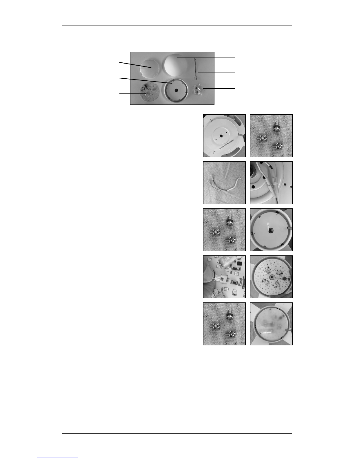
(4) If your fan was ordered/configured with a light, identify all parts as shown here
and follow steps (a) through (e). Otherwise, proceed to step (5).
(a) Remove switch housing by unscrewing and
removing three screws as shown here. Set
the screws aside for reinstallation at step (c).
(b) Depending on when your fan was
produced, a 2-pin terminal may already be
present. If so, skip to step (c). If your fan has
separate wire connectors, join the bridge
connector ends with light kit lead wires from
fan.
(c) Route 2-pin terminal through center hole
of lighting plate and secure with screws from
step (a). Be sure that all wires are inside the
outer edges of the switch housing.
Lighting plate
LED Cover
LED Board
Glass diffuser
Bridge connector
Light kit hardware
pack(s)
(d) Position and insert 2-pin connector into
block near center hole of LED board. Position
LED board flat on lighting plate so that three
cutouts are positioned over attachment holes.
Feed any excess wire back into area behind
lighting plate.
(e) Position LED cover over LED board so
that attachment holes are aligned with
cutouts and holes in adapter plate. Using
three additional, small pan head screws
included with hardware pack, secure LED
cover and LED board to adapter plate.
Note: You may store the switch housing from step (a) and the bottom dome from
step (2) for re-use in the future should you ever decide to remove your light kit.
 Loading...