

Page 1

Operating Instructions
Smok 30÷÷÷÷240kW
Automatic Biomass Burning Set
Page 2

1
Table of Contents
Dear User,....................................................................................................................... 2
1. Overview ...........................................................................................................................2
1.1. Safety Instructions................................................................................................... 2
1.2. Warranty.................................................................................................................. 6
1.3. Fuel.......................................................................................................................... 7
1.4. Technical Description .............................................................................................8
1.5. Equipment ............................................................................................................. 12
2. Assembly .........................................................................................................................12
2.1. General parameters................................................................................................12
2.2. Boiler Room..........................................................................................................12
2.2.1. Boiler Installation...............................................................................................12
2.2.2. Feeder positioning..............................................................................................13
2.3. Connecting to the Chimney................................................................................... 14
2.4. Boiler Connection to the System...........................................................................14
2.5. Protection of the installation .................................................................................15
2.5.1. An open system.................................................................................................. 15
2.5.2. Closed Systems .................................................................................................. 16
2.5.3. Thermal protection............................................................................................. 18
2.6. Installation of the control system and electric connections................................... 19
2.6.1. Description of control box.................................................................................. 20
2.6.2. Control Box Installation.....................................................................................20
2.6.3. Electric connections ........................................................................................... 22
3. Device Operation............................................................................................................31
3.1. Technical Description ...........................................................................................31
3.2. Working Settings................................................................................................... 32
3.3 Burning................................................................................................................... 33
3.3.1. Ignition ...............................................................................................................33
3.3.2. Continuous operation mode ...............................................................................34
3.3.3. Emergency operation of the boiler.....................................................................35
3.4. Cleaning, Ashes.....................................................................................................36
3.5. Program-Initiated Shutdown of AZSB..................................................................38
3.6. Emergency Shutdown of AZSB............................................................................38
4. Troubleshooting, Safe Operation Conditions.............................................................. 39
4.1. Installation of the fuel container in non-heated premises .....................................39
4.2. Anti-freeze protection ...........................................................................................40
4.3. Troubleshooting ....................................................................................................40
4.3.1. Procedure in Case of Worm Shaft Jamming...................................................... 42
5. Spare Parts...................................................................................................................... 43
5.1. Main Spare Parts List............................................................................................ 43
5.2. List of Wearable Parts*.........................................................................................43
6. Disposal ...........................................................................................................................43
“MODERATOR” Company Service Representatives.................................................... 45
Page 3
2
Dear User,
Thank you for your purchase of our equipment. We would like to
congratulate you on your good choice.
Moderator Spółka z o.o. has been manufacturing boilers utilizing
proprietary technological solutions developed in late 70’s in Hajnówka by
engineer Kazimierz Kubacki. During last twenty years these boilers have
undergone multiple technological changes and upgrades. We have also started
production of automatic feeders intended for burning crumbled solid fuels,
which combined with a boiler constitute complete Automatic Biomass Burning
Sets (AZSB). This instruction manual is based on the latest information of the
manufacturer. Due to ongoing development works on the boiler the manual is
only applicable for the boiler it is delivered with.
AZSB is intended for heating water up to maximum 80 degrees Celsius in
central-heating and hot household water installations as well as in process
installations (wood dryers, presses, etc.).
This manual has been designed to assist users in boiler installation,
operation, maintenance and servicing. It shall be read and understood before
commencing with these activities.
1. Overview
1.1. Safety Instructions
The main condition of safe boiler operation is its correct connection to the
central heating installation. This will only be possible after all connection and
operation requirements discussed in these instructions are met and complied
with. Failure to perform any action, due to involved costs of additional
equipment installation will certainly affect the safety or cause the equipment
operating costs to raise in future.
The equipment has been subjected to performance checks and tests, which
all have been performed using carefully selected accessories (safety valves,
thermal protections) and equipment. In order to guarantee preservation of
declared high performance of the equipment, manufacturer-recommended
equipment shall be used exclusively.
We would like to hereby advise against using substitute solutions, which
have not been checked with that boiler and which do not have required
approvals (Technical Supervision Office - UDT) and certificates (declaration of
conformity, CE sign). We also advise against any unauthorized changes in the
Page 4
3
equipment structure and against failing to follow safety instruction described in
these instructions.
A failure to follow these recommendations may lead to serious threats and
expose the operating personnel to health or life hazard.
In case of doubt, please contact our sales department or authorized
servicing agent.
Safety Instructions for basic activities
Maintenance – during maintenance, the device must remain disconnected from
power supply. the switch (fig. 8) must be in 0 (zero) position. During
maintenance always check tightness of connections and conditions of the cover
seals.
Leaks – when filling the tank check if there are any foreign bodies under the
cover, that could prevent it from being properly closed.
Head – keep in mind that the burner head stays hot long after the device has
been switched off. All works on the burner head may only be performed after
the temperature drops. The burner head must not be covered and must be kept
clean.
Fire safety – leaving open covers or inspection holes or overfilling the container
during burner operation may constitute an imminent fire threat. Too much fuel
in the container will prevent tight closing of the cover:
- on each visit to the boiler room (at last once per 12 – 24 hours), it is
necessary to check whether the fire water tank contains sufficient volume
of water (the recommended water volume shall fit between min and max
level indications),
- appropriate fire fighting equipment shall be available in the boiler room
(acc. to fire brigade recommendations, appropriately sized fire
extinguisher, etc.),
- do not store ashes in plastic or cardboard containers. Do not leave ashes in
premises unsupervised (even if in non-combustible containers),
Protective equipment – chips, sawdust and ashes may contain carbon
monoxide, dusts and allergens. When working with this material, use
appropriate means of personal protection. Note that ashes may contain
concealed glowing coal particles. When working with ashes, use suitable gloves.
Clothing – When working in the boiler room, due to personal safety
considerations, use infusible and non-combustible clothing.
Page 5
4
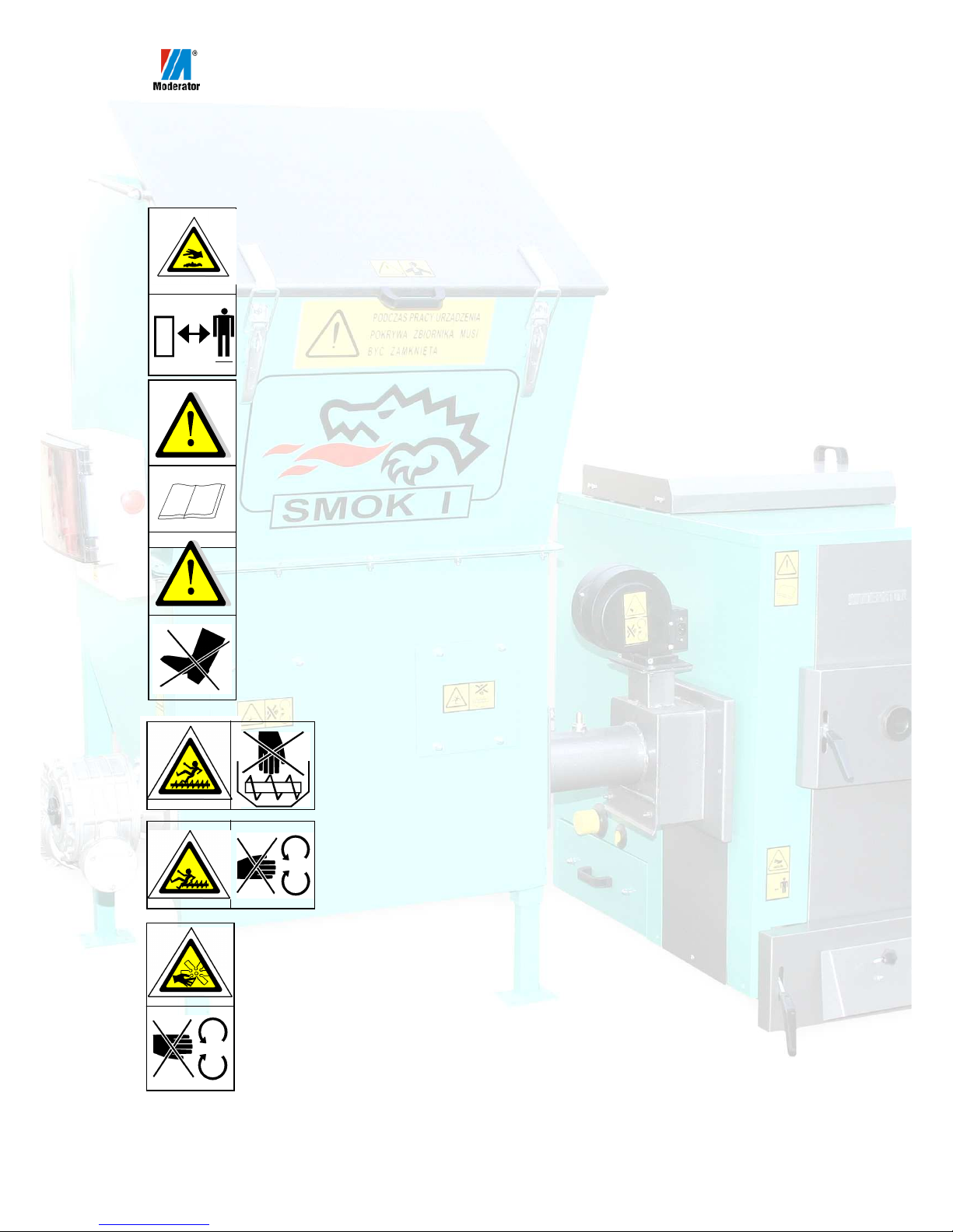
Safety and Warning Signs
Please pay attention to warning and safety signs, minding their meaning
and placement on the equipment. this is to avoid accidents.
Pay special attention in the boiler room keeping in mind that different
parts of the boiler and systems may be hot.
Keep a safe distance.
This boiler may only be operated by people knowledgeable with the
content of this instruction manual.
Do not stand on the housing.
The device may periodically switch on without warning.
Do not perform any works on a connected and switched on
device.
The transport worm may start operating without warning.
Switch off power supply before lifting the cover.
Rotating elements under caver, watch your fingers.
Page 6
5
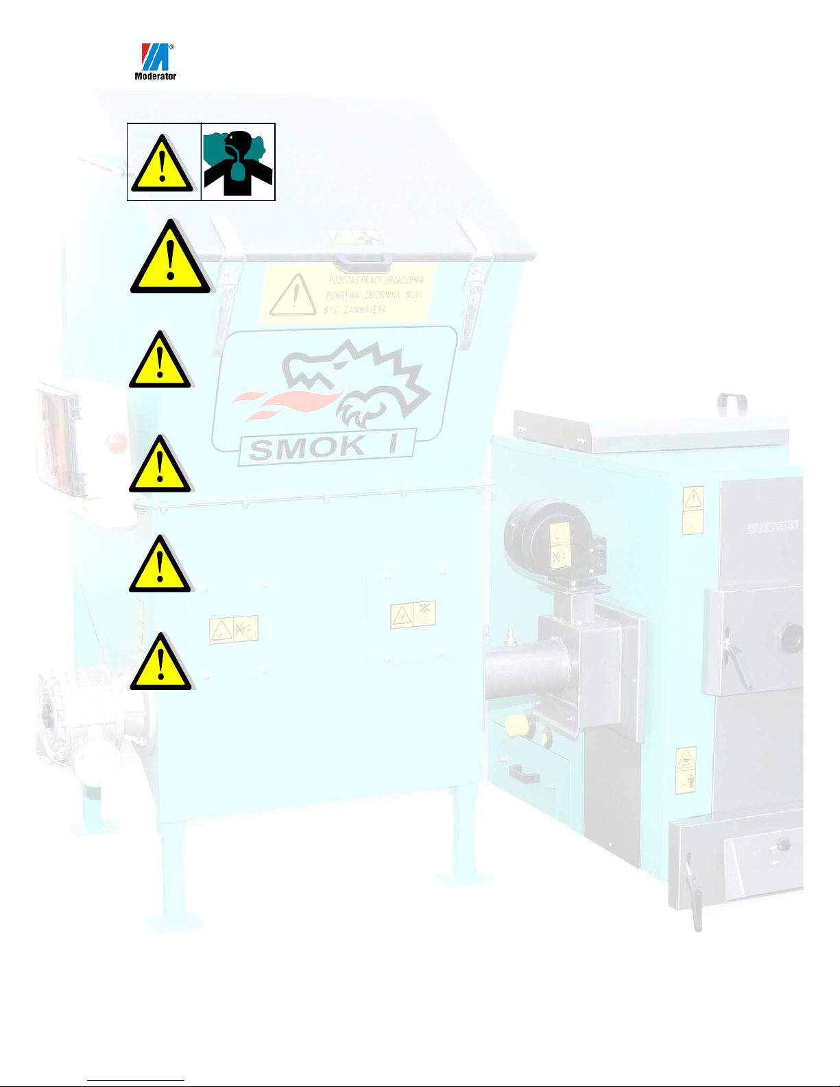
The container may contain carbon oxygen and dust. Vent
the container before commencing with loading or prior to
its opening.
This sign placed on pages of these instructions indicates a warning.
Please read corresponding section with utmost care so as to avoid many
dangerous situations in future.
Keep in that many parts and surfaces in a boiler room may have high
temperatures. Pay special attention as doors may have higher temperature than
other parts of the boiler. This also applies to smoke conduit and supply and
return pipes. When staying in the boiler room, always stay alert.
Please note that ashes and fuel may cause allergic reactions. Also, during
operation in the charging container, carbon monoxide may accumulate. We
recommend wearing protective gloves and appropriate dust masks.
Remember to keep boiler room clean and in order. Leaving fuel spills on the
floor may lead to a fire.
Note: The container cover must be opened carefully due to escaping
combustion gases and flames from the glowing fuel, forming in result of
sudden inflow of larger volume of oxygen from outside.
Page 7
6
1.2. Warranty
1. Manufacturer grants 24-month warranty for the device, which includes workmanship
and material faults.
2. Manufacturer guarantees correct operation of the Smok AZSB device, which is
confirmed by the company seal.
3. Manufacturer recommends users to follow the guidelines listed below:
• the first run of the device shall be performed by manufacturer’s service
representative * - paid service
• after first year of operation, the device shall undergo obligatory, paid inspection,
performed by Moderator service centre in Hajnówka * – this is the condition of
warranty extension onto further 12 months.
4. The warranty shall not include damages caused as a consequence of incorrect use or
normal wear and tear, refund of installation costs, refund of travel costs, damages
caused by changes or repairs performed without manufacturer’s authorization,
indirect damages and losses resulting from unproductive days and any other resulting
economic losses.
5. The warranty shall not include faults resulting from:
• failure to follow installation guidelines stated in these operating instructions or
resulting from regulations currently in force
• incorrect operation and maintenance or due to the boiler use in a way, which
conflicts with provisions of operating instructions (using incorrect fuel, leaving
ashes after the heating season, failure caused by central heating installation
freezing, inoperable or obstructed combustion gases exhaust system, shortage of
water in the installation)
• boiler application in uses other than specified in these operating instructions
• in case of incorrect selection of the boiler output to the heat demand of the object.
6. All complaints shall be always filed to the boiler vendor. Along with the complaint,
please provide the following:
• photocopy of page 6 of the operating instructions, item 7 (with entered date and
legible signature of the user)
• fault description
• a proof of device purchase
• boiler output, head rated power
•
boiler and Smok device serial numbers
7. User Statement:
I hereby declare that I have acknowledged myself with the Moderator boiler operating instructions and
that the device has been delivered according to order, new, complete and technically operational.
Additionally a specialized company has instructed me on the device operating principles and has
provided a complete set of documentation. I hereby acknowledge the recommendation of the
Moderator boiler manufacturer to subject the device to regular technical inspections. In case of
unjustified Moderator service team call to perform a warranty repair, I will cover full costs related
thereto (man-hours and costs of transport in both directions).
* For addresses and phone numbers see the last page of these
operating instructions
* „MODERATOR” Service Department – Hajnówka,
tel. 085 / 682-75-21
e-mail : serwis@moderator.com.pl
Date, company name or first and last name with legible
signature
Page 8
7
Declaration of Conformity
We,
Moderator Spółka z o.o.
11 Listopada 16a
17-200 Hajnówka
tel. (085) 682-75-20
hereby declare, on our own and sole responsibility that the product: Smok Automatic
Biomass Burning Set, with serial number starting from 250, to which this declaration
applies, meets the following requirements and standards, where applicable:
Directives Standards
98/37/WE EN-PN ISO 12100
97/23/WE
EN-PN 303-5
Hajnówka 2007.11.15
1.3. Fuel
Only recommended fuels may be used.
AZSB is designed to burn crumbled fuels from renewable sources and
wood and vegetable products, such as (chips, sawdust, bark, bricks, pellet) with
humidity content of up to 25% if cast-iron head is used or 40% if ceramic head
is used. As a substitute fuel for cast-iron heads for short period of time pea-coal
may be used. Technical parameters of the device are specified for fuels with
humidity content of up to 25% and calorific value of Q = 16.862 kJ/kg.
The higher the moisture content, the lower the calorific value. Increase of
humidity causes drop of calorific value, which means that one will need twice as
much fuel to achieve the same heating effect. A considerable part of thermal
energy is wasted in the burning process for heating up the fuel and evaporating
water (note: using wet fuel with moisture content of above 40% directly
contributes to shortening of boiler’s operational life and causes it to wear out
prematurely). Additionally there is an increased risk of moisture condensation in
the chimney. Life of a chimney exposed too condensate will be significantly
shorter than in case of a dry fuel, and the draught of the chimney will also
reduce.
During winter periods, increased moisture content of fuel creates the risk
of fuel freezing in the container, which may lead to damage of the feeding
system.
Page 9
8
Avoid burning too fine fuels, in which dust content exceeds 5%. One
shall also pay special attention when burning very dry sawdust (moisture
content up to 10%), and avoid its too tight compacting. Failure to follow
these requirements may lead to fuel sticking and if dusts are burned, to
explosion of gases inside the container.
Chips and shall be crumbled down to particle sizes of 10-30mm. If chips
are too roughly cut, there will be a risk of feeder damage.
Hygrometers are used for moisture content measurements (different types
are used for sawdust and different for wood) and these are necessary equipment,
which should be used when purchasing fuel (to check the actual moisture
content) as well as during normal operation of the device.
Approximate data of different fuels (parameters for a 30 kW device):
Time of 1 c.m.*
burning
weight of 1 c.m.
moisture content
Fuel type
( h.) ( kg ) ( % )
Bricks 96 260 10
Chips 36 155 25
Sawdust 24 145 25
Pellets 168 700 10
*c.m. – cubic meter
1.4. Technical Description
The AZSB consists of a Moderator-type boiler and Smok fuel feeder,
manufactured by Moderator Sp. z o.o. in Hajnówka. The present instruction is
applicable to all versions of the device, and that is to: :
• heat exchangers – 30, 60, 120, 240 kW
• cast-iron heads (40, 60, 120, 240 kW) and ceramic (30, 50, 100 kW)
• containers – 0.6, 1, 2, 6, 8, 10m3 and other, custom-built
Boiler
The boiler (Fig. 1) is a heat exchanger operating in upper combustion
system. Walls and grate are water cooled (the version supporting burners may
have a cast-iron grate) and are made of quality sheet metal plates.
Page 10
9
Lower-power versions of the boiler (30÷60kW) are additionally equipped
with a ceramic barrier in the combustion chamber, which ensures better afterburning of exhaust gases. All versions of the boiler may be equipped with
automatic ash removal system.
1. Ignition doors
2. Ash pan doors
3. Air throttle
4. Upper washout holes cover
5. Smoke conduit
6. Thermometer
7. Supply pipe
8. Head plug
9. Thermal protection sensor G1/2
muff
10. Ash pan washout
11. Return pipe
12. Safety valve
13. G 1/2 muff for thermostat
Fig. 1. Moderator-type boiler (version designed for use in ABB set) – main
parts.
2
1
3
4
8
5
7
12
11
10
6
13
9
Page 11

10
After the burner is disconnected, the boiler may be used for burning solid
fuels in traditional system, with manual charging of the combustion chamber.
Such burning shall be however treated as a substitute method to be used in
special situations (e.g. power supply failures, damages to the feeder, etc.) and
one shall aim at restoring the automated operation mode as soon as possible. In
the emergency mode, manual charging is performed through ignition doors (1,
Fig. 1). Bottom (ash pit) doors are equipped with an automatic gate (3. Fig. 1)
ensuring flow of air in case of a power failure.
Head
Depending on the used fuel, two types of heads may be used: cast-iron head
(for humidity of up to 25%) or ceramic head (20÷40%).
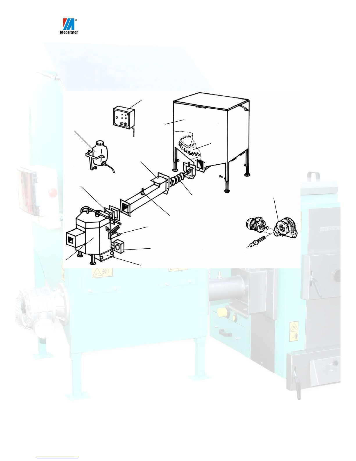
Cast-iron head (Fig. 2) is located inside the boiler combustion chamber.
The head operating principle is the following. Fuel from the container (1) is
transported to the head by a worm shaft meshed with mixers (toothed wheels). Fuel
is fed to the head grate where in very high temperature, using air supplied by the
blower, combustion process takes place. Fresh fuel supplied by the worm shaft
pushes remaining ashes to the ash pan of the boiler. Flame, which heats up the
boiler is automatically controlled by the head, according to the main control box
settings.
1. Fuel container
2. Electric motor, gears, shaft
3. Toothed wheel
4. Worm shaft
5. Head cover
6. Head
7. Blower
8. Head washout
9. Maintenance peephole
10. Supply pipe
11. Fire water tank
12. Main control box
13. Fig. 2 Cast-iron head set.
6
1
12
11
7
9
8
2
5
10
4
3
Page 12
11
Ceramic head (Fig. 3) is located near the boiler and thus only the flame
enters the combustion chamber. The operating principle of this head is the same
as of the cast-iron head, with the difference that ashes are removed to a special
washout located under the head and may be removed by emptying a special
cassette located there.
1. Fuel container
2. Electric motor, gears, shaft
3. Toothed wheel
4. Worm shaft
5. Limit switch
6. Ceramic head
7. Blower
8. Head washout
9. Maintenance peephole
10. Supply pipe with bee wax plug
11. Fire water tank
12. Main control box
13. Fixing screw
Fig. 3 Ceramic head set.
Containers
AZSB may include containers with varying volume between 0.6m3 and
10m3. The container is made of stainless steel sheet metal plates, and on its
bottom a set of mixing wheels coupled with the worm shaft is installed. The shaft
movement drives the toothed wheel (or wheels) which makes the fuel to move
downwards. Different containers may be connected to the system. Available
connections ensure equipment compatibility.
1
4
11
9
13
6
10
5
7
8
1
12
3
Page 13
12
1.5. Equipment
The boiler is being delivered in completed state. Its basic equipment
include: a thermometer, a G½(G¾) drain valve, a G¾(G1)safety valve, complete
cleaning set, a drawer, cast-iron grate (only in AZSB30).
The feeder is provided partially assembled. Some parts of the feeder, after
workshop tests are disassembled and packed inside the container. This is meant
to facilitate transport and device handling to the boiler room. The feeder is
equipped with all necessary elements permitting its installation outside the
electric installation.
2. Assembly
2.1. General parameters
Maximum supply temperature – 80˚C
Maximum return temperature – 70˚C
Minimum recommended return temperature – 55˚C
Operating pressure - 1.5 bar (for versions above 50kW – 2.5 bar)
Thermal efficiency 84%
Combustion gases minimum temperature – 150ºC
2.2. Boiler Room
The boiler room shall meet requirements of the PN-87/B-02411 standard.
Here are some of the most important of them:
• waterproof flooring
• steel or wooden doors lined with sheet metal, opening outwards
• 21x21 cm air supply hole in the bottom part of the boiler room
• at least 14x14 cm exhaust hole in the upper part of the boiler room
Equipment:
• tap
• sewage well
• sink
Forced ventilation must not be used.
2.2.1. Boiler Installation
Boiler installation shall be performed by installer with appropriate
qualifications and experience (we advice to seek help from representative
centres, whose installers have undergone training in Moderator Sp. z o.o.). A
Page 14
13
faulty installation may cause premature wear of the boiler and threatens fire or
may cause an explosion.
Moderator boilers are delivered assembled. During boiler installation, it
is necessary to ensure its accessibility in such a way, so that boiler room walls
do not render fuel charging, grate cleaning and access to the side washout and
fan difficult.
2.2.2. Feeder positioning
Installation is the same for ceramic and cast-iron head versions.
Preparation:
1. Remove from the container all loose parts, remove the grate from the
boiler (if equipped) and tightly close all air inlets to the device.
2. Make sure to leave 15÷20 cm in front of the burner head so that ashes
could freely fall into the ash pan (this can be achieved by sliding the head
into the boiler opening, prepared by the boiler manufacturer).
3. Find a place for the fire water tank and prepare a hose section of
appropriate length for installation (included in the package). In order to
ensure safe work, the water tank shall be fixed to a wall, rather to the side
panel of the fuel container. Bottom of the water tank shall be at least 50
cm above the upper surface of the supply pipe. Check that water hose is
not bent or twisted.
4. Make sure you have appropriate tools necessary to commence with
installation (a complete set of keys).
Installation (identification of parts according to fig. 2 or 3):
1. Bolt the work shaft casing on to do the container.
2. Slide in worm shaft (4) into the inside of the guide and fix it using a
M12x65 screw, fitted on the end of the worm shaft.
3. Attach the head (6) and fix it with screws (pay attention to careful
installation of the seal).
4. Screw the blower (7) to the burner head.
5. Slide in the head (or smoke conduit) to the assembly opening in the
boiler. After installation and tightening screws, in case of cast-iron head,
install head cover. Install all seals with care.
6. Install the fire water tank (11), open the tap and make sure that the tank
cover (nut) has an air suction hole.
7. Before filling the tank, fix tank’s legs by tightening counter screws
located on inner surface of legs. The tank must be levelled.
8. Connect electric installation and detectors (see description in the
Installation of the control system and electric connections, par. 2.7).
Page 15

14
2.3. Connecting to the Chimney
Boiler’s smoke conduit shall be seated directly in the chimney, and after
installation sealed along the contact line of: smoke conduit sheet metal –
chimney brick. Chimney outlet shall be located 1 meter above the roof ridge.
Square or rectangular chimneys shall be made of burnt brick; round chimneys
(usually steel ones)shall be insulated over the whole height with at least 5-cm
mineral wool layer.
When installing the smoke conduit in the chimney, one shall pay attention
to the chimney damper lever (it is necessary to provide a space needed for its
easy opening and closing).
Remember that combustion gases entering the chimney are hot,
therefore the chimney damper lever will heat up. To operate the
chimney damper, always wear protective gloves.
Boiler Power
kW
Square Chimney
cm x cm
Rectangular Chimney
cm x cm
Round Chimney
cm
up to 30 15 x 15 14 x 20 15
32-60 20 x 20 15 x 27 18
62-120 25 x 25 25
2.4. Boiler Connection to the System
The Boiler will operate correctly if the temperature inside the combustion
chamber will be sufficiently high, which means that the supply water (on the
boiler output ) shall have the temperature in the range of 70 to 800 C, and that
the water on return, not less than 550 C. Such operating parameters will protect
the boiler against low-temperature material corrosion. In order to ensure correct
operation of the boiler, the manufacturer recommends installation of a mixing
valve.
Boilers rated 30kW have connections in the form of threaded G1½ stub
pipes, and boilers rated 32÷60kW G2 stub pipes. Boilers rated above 60kW –
have DN80 flange connections. Connecting stub pipes with the installation shall
be performed using appropriate connectors. Identification of boiler parts
according to the numbering on Fig. 1.
If a boiler is fitted with thermal safety valve (SYR 5067), install valve
sensor in the G½ (9) muff (Fig. 1). Install the safety valve according to
provided valve installation instructions (p. 17). The method of valve
connection is presented on the diagram (Fig. 5).
Connect network water supply through the G½ (11) valve with a flexible
hose, which shall be disconnected after water charge is filled. During filling,
oven all venting along the installation and gradually close them after water
Page 16

15
overflows in the overflow pipe of the pressure vessel. Installations operating
without losses may be supplied with raw water, provided that its hardness does
not exceed 10n. Otherwise water shall be pre-treated.
Install boiler accessories (handles and Bakelite knobs).
2.5. Protection of the installation
2.5.1. An open system
Moderator boilers operating in open central heating systems must be
connected according to requirements of the PN-91/B-02413 standard, so that
excess heat in the form of steam shall be removed through an open connection
(RP overflow pipe) to atmosphere.
KOMIN – CHIMNEY ZAWÓR BEZPIECZEŃSTWA - SAFETY VALVE
CZUJNIK TEMPERATURY – TEMPERATURE SENSOR KOCIOŁ – BOILER
STEROWNIK – CONTROLLER WENTYLATOR – BLOWER
ZAWÓR SPUSTOWY – DRAINAGE VALVE NACZYNIE WZBIORCZE – PRESSURE VESSEL
ZAWÓR MIESZAJĄCY– MIXING VALVE ZBIORNIK AKUMULACYJNY – HEAT ACCUMULATION TANK
WĘŻOWNICA - COIL INSTALACJA GRZEWCZA – HEATING INSTALLATION
ZASILANIE Z SIECI - WATER PIPE SUPPLY
Fig. 4 Diagram of installation protection for boilers operated in open centralheating installations.
Page 17

16
Installation requirements:
• pressure vessel with the volume of at least 4% of the total water
charge
shape: cylindrical, type A. acc. to PN-91/B-02413-1-2
rectangular, type B, acc. to PN-91/B-02413-1-3
• safety riser tube (RB) with inner diameter of:
25 mm for 30 kW boilers
32 mm for 60 kW boilers
40 mm for 120kW boilers
60 mm for 240kW boilers
• riser pipe (RW) with inner diameter of:
25 mm for boilers up to 100kW
32 mm for boilers up to 300kW
• overflow pipe (RP)
inner diameters as RW and RB
• circulation pipe (RC) with inner diameter of 20 mm
• venting pipe (RO) and signalling pipe (RS) with inner diameter of
15 mm
No fittings permitting complete or partial closure of flow may be
installed on RB, RW and RO pipes. The protective equipment and
pipes shall be protected against freezing.
2.5.2. Closed Systems
Moderator boilers operating in closed systems must be equipped with air
supply system (designed by Moderator Sp. z o.o. for Moderator boilers - we
advise against installation of other air supply systems) safety valve and
additionally thermal protection permitting safe discharge of excessive thermal
power. Muffs welded in the upper jacket of the boiler are designed to facilitate
installation of this equipment(items 9 and 12 on Fig. 1).
Moderator-type boilers are manufactured according to the
EN-PN 303-5
,
standard, which permits boiler operation in closed systems, provided that
specific requirements are complied with.
Special attention shall be paid in case of boiler versions designed
for manual charging. The manufacturer’s recommended
SYR 5067 thermal protection is only and exclusively effective if
pressure in water pipe network can be guaranteed at the min. level
of 2.3 bar and if safety valve is installed.
Page 18

17
This means that the system may not operate if water from in-house water
intake is used (e.g. if power supply outage prevents hydrophore switching on),
or in places where water supply outages are frequent.
In such situations, the boiler shall not be installed in a closed system or
only its automatic version should be used (which can not burn solid fuels with
manual charging). The automatic version is equipped with a thermostatic valve,
which shuts off the device at the temperature of 95ºC.
Boiler installation without a reliable device to discharge the excessive
thermal power is forbidden.
KOMIN – CHIMNEY ZAWÓR BEZPIECZEŃSTWA - SAFETY VALVE
CZUJNIK ZAWORU TERMICZNEGO – THERMAL PROTECTION VALVE SENSOR
CZUJNIK TEMPERATURY - TEMPERATURE SENSOR KOCIOŁ - BOILER
STEROWNIK – CONTROLLER WENTYLATOR – BLOWER
ZAWÓR SPUSTOWY – DRAINAGE VALVE ZABEZPIECZENIE TERMICZNE – THERMAL PROTECTION
ZAWÓR MIESZAJĄCY– MIXING VALVE ZBIORNIK AKUMULACYJNY – HEAT ACCUMULATION TANK
WĘŻOWNICA - COIL INSTALACJA GRZEWCZA – HEATING INSTALLATION
ZASILANIE Z SIECI - WATER PIPE SUPPLY ODPROWADZENIE WODY – WATER DRAINAGE
Fig. 5 Diagram of installation protection for boilers operated in closed central
heating systems
Page 19

18
2.5.3. Thermal protection
Applications:
5067 thermal protection is designed to protect solid fuel boilers in heating installations fitted with thermostatic valves conforming to the PNEN303-5 Polish Standard. It is particularly recommended for boilers, which are not equipped with cooling exchanger. Figure 1 presents
installation principle, at a close distance from the boiler, with special consideration for such guiding and sizing of pipes so that no pressure
losses occur.
Installation and operating principle: The 5067 thermal protection valve consists of the following elements: non-return valve (1), pressure
reducer (2), thermally-controlled filling valve (3) and ejection valve (4), pressure sensor with a capillary tube(5).
The pressure reduction valve (2) is connected to the water pipe network. The output of the thermally-controlled filling valve (3) is connected
to boiler’s return line. The supply line to the input of thermally controlled ejection valve (4), which output side leads to the outlet. The
pressure sensor is installed in the warmest part, optimally in the upper part of the boiler. The pressure reduction valve is firmly set to 1.2 bar,
thus the operating pressure in the heating device shall be by 0.2 to 0.3 bar higher. This prevents opening of the safety valve in the installation.
It is recommended to use a safety valve with settings of at least 2 bars.
If the preset opening temperature of ca. 90OC is exceeded, the filling valve (3) starts to open. In order to maintain stable pressure in the
heating installation, the ejection valve opens at 97OC. After the ejection valve opens, hot water flows out of the installation and cold water
may flow in from the supply line, this cools down the boiler. When boiler temperature drops to 94OC, the ejection valve closes. Thermally
controlled filling valve and temperature sensor help to restore the correct flow pressure in the heating installation.
When the temperature reaches 88°C, also the filling valve closes.
Build:
The thermal protecting device is controlled by two independent valves: the filling valve and the ejection valve. The body of the device is a
die stamped brass element whilst other parts that contact water are made of stainless steel and temperature resistant plastic. All sealing
elements are made of resilient and high-temperature resistant, heavy duty elastomeric rubber material. Springs are made of stainless spring
steel. The sensor and capillary tube are made of copper, whereas the sleeve is additionally nickel-plated.
Valve opening is controlled by doubled temperature sensor. The fittings are self-venting. Elements of the valve, the valve seat and seal may
be removed and cleaned without any change to pre-set opening temperature. Compact head of the temperature sensor may be conveniently
disassembled during the valve body installation. The capillary tube from the sensor to actuator is protected by a special, metal flexible hose.
Pressure reducer operating pressure:
Maximum water inlet pressure:
Minimum required inlet water pressure :
Temperature
filling valve
ejection valve
Maximum operating temperature
Capillary tube
Weight
1.2 bar (factory-fixed)
16 bar
2.3 bar
of opening:: of closing:
90°C +0/-2°C 88°C +0/-2°C
97°C +0/-2°C 94°C +0/-2°C
135°C
1300 mm – standard length
1.5kg
dimensions in mm if not otherwise
stated
Page 20

19
2.6. Installation of the control system and electric connections
Safety Guidelines
1. Before connecting the device, it is necessary to read boiler and controller
operating instructions.
2. Before commencing with installation, repairs or maintenance or when
performing any connecting works, it is absolutely necessary to disconnect the
power supply and to make sure that there is no live supply on any of
terminals or cabling.
3. the boiler room shall be equipped with 400V/50Hz electric power system,
compliant with applicable regulations.
4. The electric system (regardless of its type) shall be terminated with power
supply receptacle with a protective terminal. Use of power receptacles
without connected protective terminal may cause electric shock
hazard!!!
5. The boiler shall be connected to a separate power supply line, protected with
3-phase C10A/400V fuse set and a residual circuit breaker (for shockprotection).
6. The cabined, where electrical accessories are installed may only be opened by a
qualified electric engineer knowledgeable with the device operation.
7. Location of power receptacle used for the controller connection shall be
chosen in such a way, so that the power plug is readily accessible for quick
disconnection in case of an emergency.
8. Electric cables shall be well fixed on their whole length. Wires shall be
guided away from heating parts of the boiler and in particular away from hot
elements of the head, flue conduit and chimney.
9. The control box must be installed and operated according to electric
equipment handling principles.
10. .The controller may not be exposed to water and to conditions causing water
condensation, e.g..: sudden changes of the ambient temperature.
11. The controller shall be installed in a location preventing its heating to fuse
temperatures above 50°C. It must not be installed on the fuel container wall.
12. The controller must not be operated if its enclosure is broken or damaged.
13. The controller shall be installed in a place inaccessible for children.
14. During thunderstorms the controller shall be plugged off the power supply
network.
Page 21

20
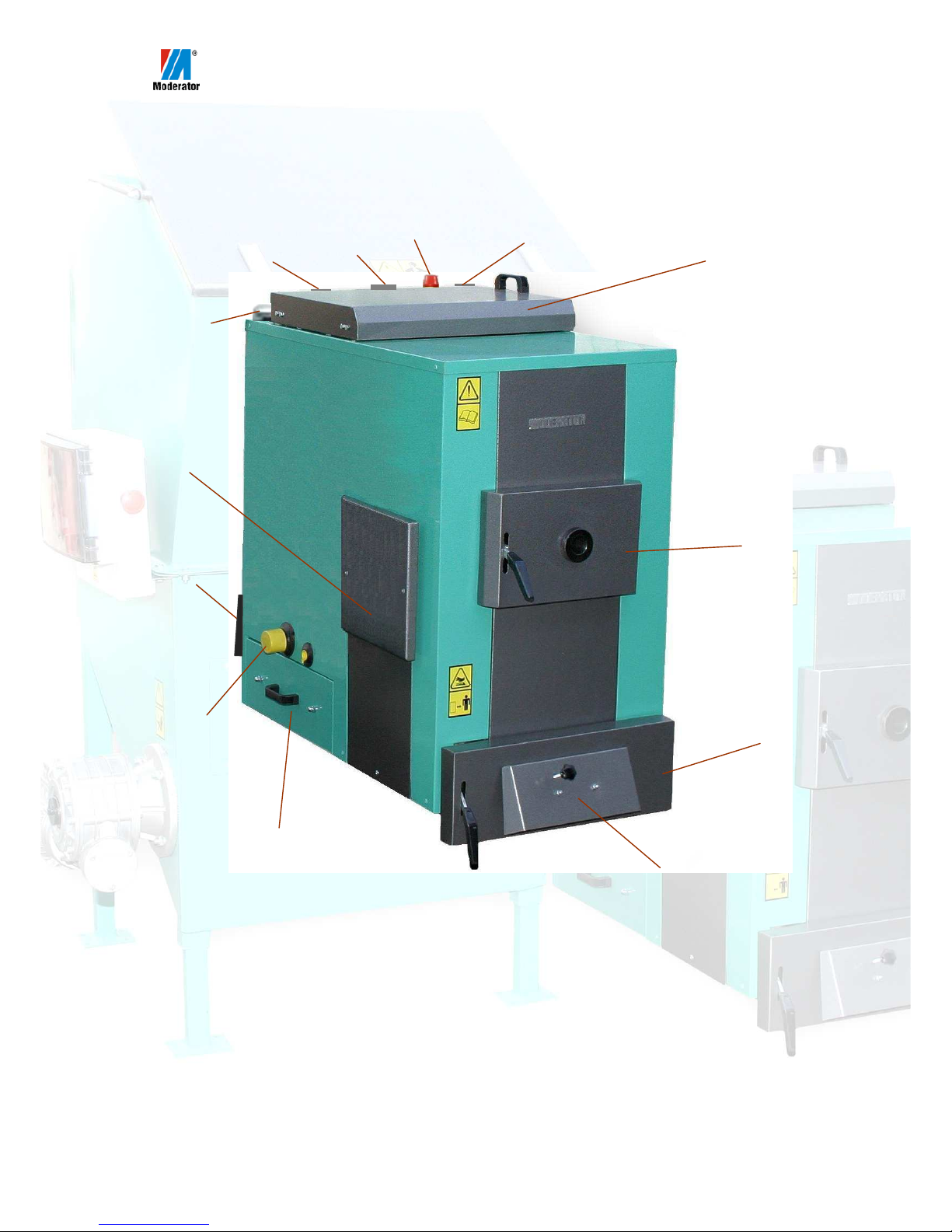
2.6.1. Description of control box
Figure 6 presents the AZSB or APSB control box cabinet.
Fig. 6. Front view of the control cabinet.
Details regarding ecoMAX 800 R controller operation and settings are
provided in the controller’s operating manual, enclosed with the set.
2.6.2. Control Box Installation.
The control box shall be installed on the boiler room wall in a place,
which will ensure easy access for maintenance purposes. Below is the
description of the control box installation procedure:
1) Remove the ecoMAX800R control box from its packaging.
2) Undo hooks (10) (fig. 6) and the front lid (1) (fig. 6).
3) Using a flat screwdriver, pry and remove 4 red plugs (10) (fig. 7) located
in inner corners of the enclosure.
4) Using a Ø8 mm drill bit, drill holes in the plastic under removed plugs.
1
2
3
6
7
8
4
9
5
10
1. Controler front panel
2. ecoMAX800 controller panel
3. Display
4. Emergency stop pushbutton
5. Cable glands
6. MENU button
7. Select / change / accept button
8. EXIT button
9. Controller power switch
10. Enclosure lid hook
Page 22

21
5) Place the control box against the wall in the place intended for its
installation and mark 4 holes (e.g. using the drill bit)
6) Using Ø8 drill bit, drill at least 80mm-deep holes in the wall .
7) Attach the box to the wall using expansion plugs.
8) Having performed all of the activities listed above, proceed with electric
connections of the device.
Fig. 7. Control box - inside view.
Cables must not be guided through the control box enclosure
without using cable glands.
The controller must not be installed on the boiler, on the worm
shaft pipe, on flue ducts, on the chimney nor on the fuel
container or on any surfaces that may heat up above 50ºC.
7
1. Motor switch aux. connector
2. Motor switch
3. Feeder contactor
4. Controller output module
5. Fuse
6. Lid closing hook
7. Sensors terminal strips
8. Terminal strip (high-voltage side)
9. PE protective line terminal strip
10. Plug
1
2
4 5
3
6
8
9
10
Page 23

22
2.6.3. Electric connections
Before commencing with electric connection, it is necessary to install the
wiring (not included) in the boiler room, according to applicable regulations.
Cables shall be guided inside casing pipes or dedicated cable trays. This work
shall be performed by a licensed electric engineer. It is recommended to use
cables with cross sections stated in Table 1 for wiring of respective circuits.
Cross-sections of cables to be used for wiring:
Table 1. Minimum required cable cross sections
Circuit Identification
Cable type
Cable cross-
section
Power supply
H05VV-F 300/500V 5x1.5 mm2
Feeder (feder motor)
H05VV-F 300/500V 4x1.5 mm2
STB
H03VV-F 300/300V 3x0.75 mm2
Blower
H03VV-F 300/300V 3x0.75 mm2
Central-Heating Pump
H03VV-F 300/300V 3x0.75 mm2
Hot Water Pump
H03VV-F 300/300V 3x0.75 mm2
Ash removal (option)
H03VV-F 300/300V 3x0.75 mm2
Mixing valve actuator
H03VV-F 300/300V 4x0.75 mm2
Connections to outputs no. 16 – 31 shall be made using the H03VV-F 300/300V cable, with cross-
section of 2X0.75MM2.
APSB or AZSB devices cooperating with the controller are connected to
terminal strips (7) and (8) (see fig. 7). These terminals can be accessed after the
front cover of the controller (1) is opened (fig. 6).
Under terminal strip (8) (fig. 7) there is a label sticker located, which is shown
on fig. 8.
Fig. 8. The label under the (high-voltage) terminal strip.
Terminals (7) (fig. 7) are identified on the label (fig. 9) located on the controller
output module, above the following terminals.
Fig. 9. Description of the sensors terminal strip.
Page 24

23
Fig. 12. Motor switch.
A
When connecting cables to the controller, remember to use cable
ferrules, which will prevent cable frying. On end sections of
cables with removed insulation, on the feeder motor side eyelet
terminals shall be crimped.
Tin-plating of cable ends connected to terminal strips is not
permitted.
POWER SUPPLY
For controller’s power supply, use a cable with the minimum cross-section as
specified in table 1. Cables shall be connected to terminals
no. 66, 67, 68, 69 of the terminal strip no. (8) (fig. 7),
identified with the symbol shown on the figure 10. The
protective wire shall be connected to a terminal of the PE
terminal strip (9) (fig. 7).
Fig. 10. Identification of terminals – power supply.
FEEDER
AZSB and APSB are equipped with 3-phase ~400V/50Hz (fig. 11a)
motors. To connect the motor use a cable with the minimum cross-section as
specified in the table 1. Winding of the motor shall be connected in star to
(fig. 11b). The motor is supplied from the terminals of the (8) terminal strip
(fig. 7) identified with the symbol shown on fig. 11c. The protective wire shall
be connected to a terminal of the PE terminal strip (9) (fig. 7).
Fig. 11. a) gear-motor, b) motor connection terminals with cover removed, c)
controller terminals used for connecting the gearmotor.
Having connected the motor, it is necessary to
check worm shaft rotation direction. In order to do
this, it is necessary to set the LIGHT mode on the
ecoMAX800 controller (see ecoMAX800 controller
operating instructions) and then switch on the
feeder. the The worm shaft shall rotate in the
direction causing the fuel to be pushed into the
head. If that is not the case, it is necessary to switch
phases on POWER SUPPLY terminals.
a) b) c)
W2 U2 V2
U1 V1 W1
U V W PE
Page 25

24
Setting the motor thermal protection switch
The purpose of the motor thermal protection switch (fig. 12) is to protect the
feeder motor against fuel feeding system overloading consequences. The motor
thermal protection switch shall be pre-set with the A knob (the arrow on fig. 12)
to appropriate current, according to the table 2. The current setting depends on
the power of used motor driving the fuel feeding system. Motor rated current is
indicated on the feeder motor rating plate.
Values of motor protection switch currents are specified in the table 2:
Table 2. Current values.
Motor
power
[kW]
Motor rated
current [A]
Current to be set on
the protection switch
[A]
0.55 1.5 1.7
0.75 2 2.2
1.1 2.8 3.1
1.5 3.4 3.8
If the protection switch is set incorrectly (e.g. too high value),
then the device may “get stuck”, which in turn may lead to
motor overheating and burning or breaking the gear-motor
fixing. Too low current may cause frequent trips of the switch.
Rated current values specified in the table 2 may actually slightly
differ from those stated on the rating plate.
BLOWER
The line that feeds the blower shall be connected to a plug (fig. 13b),
which is delivered with the device. The blower shall be supplied off terminal
strip (8) terminals (fig. 7) identified with the symbol presented on figure 13c.
The protective wire shall be connected to a terminal of the PE terminal strip (9)
(fig. 7). The recommended cross-section of the cable used to connect the blower
is specified in the table no. 1.
Fig.13. a) view of the blower (cast-iron type), b) blower plug, c) identification of
connection terminals.
a) b) c)
Page 26

25
SAFETY TEMPERATURE BREAKER – STB
Fig.14. a) STB temperature limiter, b) STB with cover removed
The role of the safety temperature limiter STB (fig. 14a) is to disconnect blower
and feeder power supply when the temperature exceeds 95°C on the central
heating system supply pipe. The limiter is installed directly on the boiler, close
to the power supply pipe, as shown on fig. 15a. Having undone 4 screws, the
enclosure lid shall be removed. Next the limiter box shall be installed on the
boiler using 2 screws in openings (W) (fig. 14b). Cables are attached to the
connector (Z) (fig. 14b). the protective line is connected to the terminal
identified as PE. Remaining two lines are connected to terminals C and 2. If
cables connected to terminals C and 2 are exchanged, this will not affect the
controller nor STB operation. On the side of the controller, the cable shall be
connected to terminal strip (8) (fig. 7) terminals identified with the symbol
shown on figure 15b. The protective wire shall be connected to a terminal of the
PE terminal strip (9) (fig. 7). The recommended cross-section of the STB
connection cable is shown in table 1. The STB capillary and the boiler
temperature sensor shall be attached to the supply pipe with the fixing clip
(delivered in the kit) within 10÷15 cm away from the stub pipe or the connecting
flange (fig. 15a). Having performed all of the above tasks, the sensor shall be
thermally sealed with the pipe.
a) b)
W
W
Z
Page 27

26
Fig.15. a) STB installation, b) identification of controller terminals
Regulations in force require safety time limiter installation.
CENTRAL HEATING PUMP
The circulating pump shall be connected to terminal strip (8) (fig. 7) terminals
identified with the symbol shown on figure 16. The protective
wire shall be connected to a terminal of the PE terminal strip (9)
(fig. 7). The recommended cross-section of the wire used for
pump connection is presented in table 1. Connection on the side
of the pump shall be made according to the pump manufacturer’s
technical documentation.
Fig.16. Identification of connecting terminals.
HOT WATER PUMP
Hot water container pump shall be connected to terminal strip (8) (fig. 7)
identified with the symbol shown on figure 17. The protective
wire shall be connected to a terminal of the PE terminal strip (9)
(fig. 7). The recommended cross-section of the wire used for
pump connection is presented in table 1. Connection on the side of
the pump shall be made according to the pump manufacturer’s
technical documentation.
Fig.17. Identification of connecting terminals.
Fixing clip
BOILER
TEMP.
SENSOR
STB
STB CAPILLARY
a)
b)
10÷15 cm
THERMAL
INSULATION
Page 28

27
ASH REMOVAL
The cable used to connect the ash removal system motor shall have
the cross-section specified in table 1. Ash-removal motor winding
shall be connected according to the diagram located inside the
connection box.
Fig.18. Identification of connecting terminals.
Power supply of the ash removal motor shall be connected to terminals shown
on figure 18. The protective wire shall be connected to a terminal of the PE
terminal strip (9) (fig. 7). After the motor is connected, it is necessary to check
form worm shaft rotation direction. The worm shaft shall rotate in the direction
causing ash to be pushed off into the container. If this is not the case, then it is
necessary to change motor wiring connections.
The ash removal system is standard feature in AZSB 100 GC,
AZSB 120 GŻ, AZSB 240 GC and GŻ units.
MIXING VALVE ACTUATOR
The mixing valve actuator shall be connected to the terminal
strip (8) (fig. 7) terminals identified with the symbol shown on
figure 19. The protective wire shall be connected to a terminal
of the PE terminal strip (9) (fig. 7). The recommended crosssection of the actuator’s connecting cable is stated in table 1.
Fig.19. Identification of connecting terminals.
The actuator supports only mixing valve servos equipped with limit switches.
Use of other mixing valve servos is not allowed. One may use actuators with the
full rotation time between 30 and 255s.
Detailed information regarding connection and configuration of the controller to
support the mixing valve actuator can be found in the controller operating
instructions, enclosed with the boiler.
BOILER TEMPERATURE SENSOR
The boiler temperature sensor shall be connected to the supply pipe as shown on
fig. 15a and connected to terminals no. 16 and 17 of the controller, which are
identified with the symbol shown on figure (fig. 20). In order to extend the
sensor cable, one may use a cable with cross-section stated in table 1, which
does not exceed 10 m in length, as this may adversely affect temperature
readouts accuracy. Installation of sensor cable along power supply lines shall be
avoided. It is necessary to maintain at least 10 cm spacing.
Page 29

28
Fig.20. Identification of connecting terminals czujnika temp. kotła.
The sensor shall be installed dry.
Do not prime with oil or other liquids!!!
FUEL FEEDER TEMPERATURE SENSOR
The measuring sensor (C) (fig. 22) shall be installed in the (T) sleeve and fixed
by tightening the (S) screw. In order to prevent sensor’s metal enclosure against
damage, the screw shall be tightened by hand rather than using a key or a
wrench. Connect the sensor to terminals no. 18 and 19 of the controller, which
are identified with the symbol, as shown on fig. 21. In order to extend
the sensor cable, one may use a cable with cross-section stated in table
1, which does not exceed 10 m in length, as this may adversely affect
temperature readouts accuracy. Installation of sensor cable along
power supply lines shall be avoided. It is necessary to maintain at
least 10 cm spacing.
Fig.21. Identification of connecting terminals.
Fig.22. Feeder temperature sensor installation.
S
C
T
Page 30

29
HOT WATER TEMPERATURE SENSOR
The sensor shall be installed in the hot water contained in a dedicated place.
Connect the sensor to terminals 20 and 21 of the controller identified with the
symbol as shown on fig. 23. In order to extend the sensor cable, one
may use a cable with cross-section stated in table 1, which does not
exceed 10 m in length, as this may adversely affect temperature
readouts accuracy. Installation of sensor cable along power supply
lines shall be avoided. It is necessary to maintain at least 10 cm
spacing.
Fig.23. Identification of hot water sensor connecting terminals.
FIRST MIXER TEMPERATURE SENSOR
If a mixing valve with an actuator is used, the actuator shall be connected with a
mixer sensor. Connect the sensor to terminals no. 22 and 23 of the controller,
identified with the symbol as shown on fig. 24. In order to extend the sensor
cable, one may use a cable with cross-section stated in table 1, which
does not exceed 10 m in length, as this may adversely affect
temperature readouts accuracy. Installation of sensor cable along
power supply lines shall be avoided. It is necessary to maintain at least
10 cm spacing.
Fig.24. Identification of mixing valve temperature sensor connecting terminals.
In case of extended central heating systems with more than one mixing valve
actuators, it is possible to expand the controller with additional expansion
module MX.01, which supports two mixing systems.
WEATHER SENSOR
This sensor shall be installed on the coldest wall of the building (usually this
will be the northern face), under a hood or an awning. The sensor must not be
exposed to direct sunlight nor rain. The sensor shall be installed at least 2m
above the ground level, far from windows, chimneys and other sources of heat
that could affect temperature readings (at least 1.5m away). The sensor shall be
connected to terminals 24,25 of the controller, identified with the symbol as
shown on fig. 25. To connect the sensor, one may use a cable with
cross-section stated in table 1, which does not exceed 10 m in length,
as this may adversely affect temperature readouts accuracy.
Installation of sensor cable along power supply lines shall be
avoided. It is necessary to maintain at least 10 cm spacing.
Fig.25. Identification of weather sensor connecting terminals .
Page 31

30
FUEL LEVEL SENSOR (applicable to versions with a ceramic head)
Te limit switch of the head fuel level sensor is accessible after the yellow cover
(O) is removed (fig. 27). Cables shall be connected to COM, NO terminals of
the (W) limit switch. Normally-open (NO) terminal. When the
„tongue” located in the combustion is lifted, the circuit shall be
closed. The limit switch cable shall be guided through the cable gland
(D) located on the bottom of the yellow cover. On the controller side,
the cable shall be connected to terminals no. 26 and 27 (fig. 26).
Fig.26. Identification of the fuel level sensor connecting terminals.
If the fuel level is exceeded, the limit switch will trip. The controller will stop
feeding fuel to the burner head. The fan will continue to operate. The fuel will
burn off and the fuel level will drop, the limit switch will open and feeding will
restart. If the limit switch does not re-close within 30 minutes, a warning
message “HEAD FULL” will be displayed. The controller will switch to STOP
mode and pumps will continue to operate.
Fig.27. Location of the limit switch
If outputs 26 and 27 are not used (this is the case in cast-iron
head versions of the unit) then after the temperature sensor is
connected, one may enable the return protection function in the
controller.
The following table presents maximum loads of respective outputs.
D
W
O
Page 32

31
Table 3. Maximum output loadings.
Circuit Identification Maximum current [A] Remarks
1.7 (0.55kW)
2.2 (0.75 kW)
3.1 (1.1 kW)
Feeder
(Feeder motor)
3.8 (1.5 kW)
depending on the
rated power of the
motor used
Blower
2.6
Central Heating Pump
2.6
Hot Water Pump
2.6
Ash Removal (optional)
2.6
Mixing Valve Actuator
2.6
KEEP IN MIND THAT THE TOTAL CURRENT OF ALL DEVICES CONNECTED TO THE
CONTROLLER (BLOWER, CENTRAL HEATING PUMP, HOT WATER PUMP, ASH
REMOVAL, MIXING VALVE ACTUATOR) MUST NOT EXCEED 6A.
3. Device Operation
3.1. Technical Description
The worm shaft feeds the fuel to the burner at a pre-programmed rate. The
device is designed to work in such a way so that the flame in the grate does not
go out. This is ensured by flame suspension function, which remains active
when the water in the central heating system meets preset values. In the Run
mode <OPERATION> the feed parameter („feeding time - operation”) sets the
duration of the worm shaft feeder operation and the pause parameter („feeding
stop - operation”) sets the duration of pauses between its activation. When the
water in the boiler achieves the temperature set on the controller, the device will
automatically switch to the <CONTROL> mode. In this mode the feed and the
pause parameters have the same meaning, whereas the pause parameter is scaled
in minutes. Additionally the device operation is assisted by thermostatic sensors
responsible for maintaining the preset temperature of supply water from the
boiler and for control of head correct temperature and overall safety.
Page 33

32
3.2. Working Settings
Duration of the „feeding time - operation” and „feeding stop - operation”
periods must be set according to the actual type of fuel used. The following table
presents approximate pres-et times for various devices, depending on the type of
fuel used.
Head Power Fuel type Container Volume “Run” mode “Suspend mode”
feeding time - operation (s) feeding time - operation (s)
(kW) (m3) feeding stop - operation (s) feeding stop - operation (min)
(min.)
40 sawdust 0.6 5 6
20 9
40 bricks 0.6 3 4
40 12
50 chips 1 5 4
25 10
100 sawdust 6 15 10
35 6
120 pellet 10 5 4
40 6
The pause duration in the <CONTROL> mode may not bee too short and
too long in the <OPERATION> mode, as water in the boiler is already hot, and
if overheated may cause the overheat protection system (STB) to trip and
automatically switch off the device.
This problem may be particularly visible in spring, when user forgets to
change the control box settings despite the increase of the outdoor temperature.
The device must operate using both these modes. The
<CONTROL> mode must be initiated and last significantly
longer than the <OPERATION> mode. This will ensure
appropriate head cooling. If during operation user connects
additional heat loads, then the thermal power may be insufficient
and in such case the system will only work in the
<OPERATION> mode. This may lead to the head overheating
and cause it to wear prematurely.
Supply water temperature setting
Temperature of supply water is measured by a thermostatic sensor
installed close to the boiler supply pipe or directly on the pipe. The temperature
shall be set to ca. 800 C, which will allow to ensure its optimum performance.
Appropriately selected parameters will affect combustion parameters, including
the temperature of combustion gases. The temperature of gases in the chimney
may not be too low, as it will cause condensation, which will damage the
chimney and the boiler. On the other hand, too high combustion gases
temperature will result with unnecessary heat losses.
Page 34

33
Blower air volume control
The correct volume of air needed for combustion can be determined by
watching the colour of the flame: optimum colour is yellow. A smoking, dying
down flame requires more air. Sharp, short flame, some times lightly bluish or
transparent indicates too much air. The air volume can be modified via the
control box menu. Additionally the blower has mechanic throttle to control air
flow. The throttle is equipped with a spring preventing complete shut-off of air
supply.
Feeder maximum temperature adjustment
The flame sensor measures the temperature on the feeder. The upper
threshold of the feeder anti-overheat protection is set from the main control box.
If the feeder temperature exceeds the preset value, then the controller will stard
the feeder for a pre-programmed time of 8min. During this time air supply will
be shut off and pumps will be on. After the fuel is “pushed out”, the controller
will switch off the feeder and will no longer switch it on, even if the feeder
temperature is still high.
3.3 Burning
3.3.1. Ignition
For ignition, use dry duel with humidity content of up to 20%. Firelighters
may be used, paper (except from newspapers) or cardboard. A batch of fuel shall
be fed into the head’s combustion chamber manually, after the mode is switched
to LIGHT, on the controller, with the feeding being switched on. When the fuel
appears on the burner grate, it shall be ignited and the blower shall be started
using the blower fan switch.
After about 5 minutes the flame should stabilize. Then, one shall press
EXIT and the controller will resume operation in automatic OPERATION
mode. If the fuel batch fed puts out the flame, the procedure shall be repeated.
The activities are the same for both head types: the cast-iron head requires no
further maintenance and after ca. 1 hour may be left unattended.
In case of ceramic heads, first ignition of the boiler involves also drying
and burning-in the combustion chamber (use dry fuel with humidity content of
up to 20%). The process shall last ca. 3 days. The combustion chamber burningin shall be performed in such a way, so that the brick colour lightens. Having
completed with the boiler drying, it is necessary to stop and cool it down
naturally by some 12 hours. Before the next (and each successive) start of the
feeder, in order to prepare it for continuous operation under full load, it is
necessary to warm up the ceramic chamber first, then switch to continuous
burning. For burning, use fuel with moisture content of 20 to 40% (provided that
the burning process runs continuously, in appropriately preheated chamber).
Please keep in mind that if the chamber is not sufficiently heated up, wet fuel
Page 35

34
may simply put down the flame. It is necessary to pay attention to correctness of
the <CONTROL> mode settings as too much fuel may cause the limit switch to
trip (protecting against head combustion chamber overloading) and stop the
device, which will require it to be re-ignited.
Do not use oil, gas, solvents nor any other flammable material
constituting an explosion threat for igniting the boiler.
3.3.2. Continuous operation mode
During operation, BOILERS with cast-iron heads do not require
monitoring in between fuel charging into the fuel container. Boiler cleaning and
ash removal may be performed once per week and ash removal from the boiler’s
rear chamber, once per month. After at least 3 months of operation, it is
necessary to remove burnt impurities (e.g. sand) from the head washout. Ash
removal may be performed after the power supply switch is set to “0” (zero).
Do not charge the fuel directly to the boiler combustion chamber. This
may cause damage to the head. When burning fuels (mainly sawdust) with
high dust concentrations, boiler doors must not be opened during burner
operation under no circumstances. Sudden inflow of air may cause
explosion. Do not permit the head to work partially immersed in ash. Poor
cooling of the head may quickly lead to damage of its steel casing or
cracking of grate plates.
During ceramic head operation, washout under the head may require
cleaning even as much as once per 2 days. As the head is installed by the boiler
the fuel may be periodically charged to the boiler’s combustion chamber (e.g.
fragmented wood). However this may only be performed assuming max care,
after the power supply switch is set to “0” (zero).
The ceramic head consists of a metal external casing and a ceramic heatproof chamber located inside it. The external casing has the form of a double
coat ensuring head cooling and guiding the combustion air flow (air, before it
reaches the grate is pre-heated). The heat-proof chamber acts as a thermal
accumulator, with its three-part cast-iron grate installed in its lower part, on
which burning process takes place.
During operation, the grate must be tightly closed (a hold down
screw is used for this purpose).
Inside the chamber, on a special heat-resistant pipe a dosing diaphragm is
installed. Swing-mount plate prevents excessive filling of the head’s combustion
chamber with fuel (when the plate is lifted, limit switch is activated and feeding
stops).
Page 36

35
The dosing diaphragm is activated in emergency situations only
(e.g. when the flame is suppressed with insufficiently preheated
chamber, charged with wet fuel) and it requires operating
personnel intervention and boiler re-ignition.
The fire protection system is consist of a container and a line connecting it
with the stub pipe (10) located on the worm shaft guide casing. The stub pipe is
filled with beeswax. When the casing temperature increases, the beeswax melts
and fire is extinguished.
The fire protection system is activated in emergency situations
only. After activation of the system, the operating personnel
intervention and boiler re-ignition are required. Before start-up,
it is necessary to replenish the beeswax at the stub pipe, if
necessary. Unscrew the stub pipe, fill it with wax and after
cooling down, screw in onto its place again.
3.3.3. Emergency operation of the boiler
This function shall be used in emergency situations only. In case of castiron heads, the feeder shall be disconnected and the assembly opening sealed
with heat-resistant brick and protected by means of bolted steel flap. In case of
the ceramic head, is not necessary to disconnect the feeder, one however needs
to protect the inlet to the head smoke conduit (e.g. by covering it with a steel
flap).
In case when the boiler is connected in a closed system, it must not be used
without manufacturer-recommended protections (see chapter 2.5.2).
When igniting, do not fill the whole combustion chamber (wood - 50% of
filling, coal – not more than 20%). Fuel should not have moisture content higher
than 30%. Do not use fine coal.
In any case do not burn PVC products: food products packaging (butter or
margarine boxes), toys, plastic building materials; PA products, e.g. textiles.
Some types of plastics, such as PE, PP, PET may be burned if their volume
relative to the volume of charged fuel does not exceed 5% and their burning
temperature exceeds 85ºC.
During normal operation of the boiler, it is necessary to periodically
monitor and supplement the fuel reserve. In order to achieve possibly the most
stable temperature of supply water, it is necessary to:
• use fuel with humidity content of up to 30%
• In case of higher moisture contents, fuel shall be dried or mixed with
dry one, keeping in mind that the more wet is the mix, the less dose and
the more surplus air must be used
Page 37

36
• when using fuel with different granulation, it shall be charged
alternatively (large granulation fuel already glowing in the combustion
chamber shall be supplemented with finer grained fuel, e.g. from
sawmills – as in other way they will spill through the grate)
• if possible avoid opening the charging flap during ignition and during
boiler temperature increase phase.
Note: avoid burning fine fuels, in which dusts concentration exceeds
5%. Pay attention when burning very dry sawdust (moisture content
up to 10%), do not compact them tightly in the combustion chamber.
Having charged sawdust, leave free space in the rear part of the
chamber to ensure air access. Failure to meet these requirements
may result with gases from combustion chamber backdrafting during
sudden opening of the charging flap. When the charging flap is
opened, this may cause sudden growth of the air volume in the
combustion chamber and explosive combustion of dusts.
When operating a boiler with air supply system, do not open the charging
flap during fan operation. Before supplementing the fuel, switch off the
controller.
• adjustment of the boiler performance, and thus the supply water
temperature shall be performed by changing the setting of the
throttle (or the ash pan doors adjustment slot) or by changing the
cross-section of the combustion gases outlet in the smoke conduit.
When operating a boiler with air supply system, the ash pan flap
shall remain closed.
3.4. Cleaning, Ashes
Boiler
Grate cleaning is performed when water temperature starts to drop and
when the ash pan illumination reduces. Ash shall be removed while the flame is
reduced.
In order to ensure fuel economy, keep internal chambers of the boiler and
spaces between water tubes clean. An indication suggesting that cleaning is
required is reduced chimney draught. Insufficient air will cause the boiler to
excessively smoke.
Cleaning is performed on extinguished boilers.
Page 38

37
In case of heavy contamination of the boiler, chemical agents removing
boiler deposits may be used, but only such, which are allowed on the marked
(i.e. with CE mark and instructions of use).
Fig. 23 Boiler cleaning diagram (the figure presents 30 kW exchanger cleaning
(120 and 240kW models have different cross-section, yet the cleaning approach
remains the same).
Combustion gases leaving blocked chimney are dangerous.
The chimney and the conduit shall be kept clean; they shall be cleaned
before each heating season.
The Feeder
For description of head cleaning, see item 3.4.2.. In case of the container,
it requires no maintenance during the heating season. After the heating season's
end, it is necessary to disconnect the head from the boiler and to inspect the
grate. Remove deposit from cast-iron elements, check cast-iron surfaces (for
cracks), clean air inlet holes. After cleaning, reinstall the head. If seals are
damaged during maintenance work, replace them with new ones.
Inspect the feeder container, remove the toothed wheel(s), remove
compressed fuel from under the plate, check straightness of the worm shaft and
reliability of threaded connections.
Page 39

38
Ashes
Ashes shall be removed with the device switched off. In case of cast-iron
heads it is sufficient to remove ashes once every 2 weeks. In case of ceramic
heads, the washout under the head needs to be emptied once every 2 days.
Ash handling procedure is described in p.1 “Safety Instructions”
3.5. Program-Initiated Shutdown of AZSB
Boiler
After the fuel burns out, open all doors and maximally open the damper in
the smoke conduit. Remove ash, clean the boiler. Do not drain the circulating
water. Cool down time is equal to the ignition time.
Feeder
If the fuel in the container is supplemented on ongoing basis, the feeder will
work continuously. In order to stop the device, e.g. to prepare it for ash removal,
place the power supply switch in „0” (zero) position.
3.6. Emergency Shutdown of AZSB
Boiler (applies to the emergency operation mode after feeder disconnection)
In case of emergency states, such as exceeded 1000 C temperature,
installation elements breaks and loss of water charge, control & automatic
equipment or protection equipment failure or sudden pressure increase, it is
necessary to:
• remove fuel from the grate and move outside the boiler room
• lower circulating water temperature by adding cold water to the water
charge, like during filling
• maximally open the smoke conduit throttle (if installed)
In case of boilers operating in closed system, an emergency condition may
be any condition resulting from power outage (pumps stop) or from leaving doors
of the boiler open. The central-heating installation shall be protected with a safety
valve set to 2 bars, additionally the manufacturer shall protect the boiler with
safety valve, factory preset to 2.5 bar, however in case of an emergency condition,
such protections are insufficient. The boiler must be additionally protected with a
thermal protection valve, which will remove the hot water from the boiler in case
of an emergency condition, while at the same time supplementing thus caused
shortage of water in the boiler with cold water from water pipe installation in
order to cool down the boiler and to reduce the pressure (section 2.6).
Keep in mind that emergency conditions are likely to occur during summer,
when only household hot water is heated in the boiler. Anticipating such
conditions, it is worth to consider installation of a heat accumulator capable of
taking over the heating power surplus unavoidable in such circumstances.
Page 40

39
The glowing fuel must not be extinguished or cooled down with
water.
Feeder
Set the fuel supply switch in “0” (zero) position. Set the blower switch in
the blower (<dmuchawa>) position, switch off feeding – press the red button on
the emergency switch. The blower will continue to work and burn out the fuel
on the grate and then it will start to cool down the head. Open the chimney
damper in the boiler. After the fuel burns out, boiler doors may be opened in
order for the boiler to cool down. When the temperature starts to drop, switch
off the device.
4. Troubleshooting, Safe Operation Conditions
The main precondition of boiler safe operation is construction of its
installation and protections according to Polish standards.
In order to maintain safe operating conditions of the boiler, it is necessary
to follow the principles listed below :
• wear protective gloves and goggles
• do not block charging flaps and ash pan doors
• grate change shall be performed using the ash pan lever
• use portable 24V lamps
• maintain order and cleanness in the boiler room
• maintain good technical condition of the boiler and its related
installation
• during the winter season ensure that the heating process is
continuous
If water freezing in the installation is suspected, check whether
safety piping is not blocked. The water added to the water charge
in the installation shall return through the overflow pipe from the
pressure vessel. If safety piping is blocked, the boiler must not be
ignited, and if it has been operating, proceed as in boiler
emergency shutdown procedure (see p. 3.5.)
4.1. Installation of the fuel container in non-heated premises
Installation of the fuel container in unheated premises does not constitute
a problem to the container operation as such. However condensation resulting
from changes of atmospheric conditions, combined with the heat conducted by
the worm shaft may cause the device to freeze when the outdoor temperature
drops.
Page 41

40
4.2. Anti-freeze protection
To prevent damages caused by frost, the main pipe and the bottom of the
container may be thermally insulated and additional defrosting device may also
be installed.
Thermal insulation of the main pipe and the tank bottom is sufficient
when the fuel is dry enough and stored indoors. The main pipe shall be insulated
with mineral wool on its whole length in unheated premises, and on 1 m section
in heated premises. Appropriate insulation of the bottom requires supporting
brackets to be bound with the gear and the main pipe and welding of wires
guided through mineral wool slabs on the bottom of the container. Finally
mineral wool slabs shall be protected against rain.
If the fuel has been dried and stored outdoors, the best way of protecting it
against frost is to use an insulation and a resistor installed in corners of the box,
e.g. using an aluminium tape, wrapped under the main pipe. The mineral wool in
such case is placed above the resistor.
We recommend to use automatic, frost-proof resistors, which are available
in multiple configurations.
Note: Despite this effort, in particular if wood chips are used as
fuel, the fuel may jam in the worm shaft. Any remains shall be
removed before the start of the heating season and at least once
during the season.
If a water container is located in this premise, it will be necessary to use antifreeze agent.
Note: Gas pressure drops when temperatures drop. due to this gas
cylinders of the container flap will behave differently under such
conditions.
4.3. Troubleshooting
No.
Fault Cause Remedy
- no fuel in the container or
too low fuel level,
- fuel clogging,
- container cover not fully
closed
- supplement fuel in the
container,
- mix the fuel,
- check the cover tightness
1 Flame backdrafting
to the fuel container
- blocked worm shaft
- power outage for a longer
period
- no water in the container
- determine the cause and
remove the failure
- empty the container of the fuel
and fill the worm shaft line with
water
- supplement water in the
Page 42

41
container
- insufficient chimney draught - use an exhaust fan, improve
the draught
2
Fuel clogging in the
container
- using sawdust with dusts
content of more than 5%,
- too high moisture content in
fuel (above 40%), the fuel
freezes to container walls
during the winter season
- change the fuel
- add a portion of dry fuel and
mix it thoroughly
3
Smoke in the
container
- head contamination
- blocked chimney
- boiler cover and doors not
fully closed
- clean ash in the head
- clean the chimney
- close covers and doors in the
boiler
4
Worm shaft does
not rotate
- power outage
- worm shaft blocked
- damaged worm shaft and
toothed wheel
- start left rotation, then restart
(see par. 4.3.1.)
- replace the worm shaft,
replace toothed wheels
5
Loud operation of
the feeder unit
- damaged electric motor
bearing ,
- gear-motor oil leak,
- damaged toothed wheel
bearing,
- foreign body (e.g. metal) in
the worm shaft pipe
- replace the bearing
- seal any leaks, add oil,
- replace the bearing
- remove the worm shaft,
remove the foreign body
6
Ceramic head
Quick deposit
build-up
Excessively fast
lining wear
Incorrect gassing
process in the
combustion
chamber
Smoke in the boiler
room
- excessively contaminated
fuel
- the head chamber has not
been sufficiently pre-heated
- the lining was damaged
(e.g. during cleaning), too dry
fuel used
- too low temperature inside
the chamber
- to high moisture content in
fuel
- limit switch incorrectly set
- head cover not fully closed
- insufficient chimney draught
- container cover not fully
closed
- do not burn coal, coke, fine
coal, plastics and rags, use fuels
according to the instructions,
- remove deposit
- heat-up the chamber (par.
3.4.1)
- regenerate the lining, use fireresistant cement
- incorrect ignition process (par.
3.4.1)
- add dry fuel
- adjust the limit switch
- close the cover
- use exhaust fan, improve the
draught
- check seal tightness, close the
cover
7
Cast-iron head
Quick deposit
- excessively contaminated
- do not burn coal, coke, fine
coal, plastics and rags, use fuels
Page 43

42
build-up
fuel
according to the instructions,
- remove deposit
8
Boiler can not reach
the preset
temperature
- contaminated fan
- too much ash in the (cast-
iron) head, blocked ventilation
openings in the head
- too high moisture content of
fuel,
- incorrect controller settings
- clean fan blades
-remove ashes from the head
through the washout opening
- charge correct fuel
- set correct feed and pause
times
9
Fire water tank
emptying
- flame backdrafting to the
fuel container
- undo the connector, insert
beeswax plug. If the container
has been emptied when using
sawdust, the pipe must be
cleaned off the fuel as soon as
possible, as sawdust expands
and may permanently block the
machine – immediately force
feeding of the combustion
chamber with fresh fuel.
4.3.1. Procedure in Case of Worm Shaft Jamming
The device has stopped: - Make sure, that the device is really switched off. If
the boiler is in the flame suspend mode, the blower and the worm shaft may not
rotate for longer periods.
The device has stopped (and has cooled down): - Boiler may have overheated
causing the device to shut down. Restart the controller.
The device has stopped (display message „BLOKADA PODAJNIKA” - /feeder
jam/):
- It is likely that a stone, a root, etc. from peat or chips got into the system
through the worm shaft. Re-engage the thermal protections switch.
If the feeding worm shaft does not rotate in the forced supply mode, the
following procedure shall be followed:
- Open the manhole and perform an inspection,
- Sometimes it may be necessary to switch the worm shaft in backwards
direction. For this purpose, having previously disconnected power supply,
exchange any 2 phases and switch the controller and feeding briefly on.
- Remove scale, root etc. causing the failure through the inspection
manhole.
- Make sure that the worm shaft operates correctly and tightly close the
manhole.
Page 44

43
If the engine runs and the worm shaft does not turn – that may be caused by a
foreign body at the bottom of the worm shaft. To remove this failure, it will
be necessary to remove the fuel from the container under the located jam spot
and then clean up the worm shaft.
5. Spare Parts
5.1. Main Spare Parts List
No.
Part name Part No.
1. Electric motor with gear-motor 2
2. Toothed wheel 3
3. Worm shaft 4
4. Limit switch 5
5. Main electric control box 12
6. Ceramic head (30,50,100) 6a
7 Cast-iron head (40,60,120) 6b
Part numbers are applicable to figures no. 2, 3 page 9, 10 of the instructions.
5.2. List of Wearable Parts*
No.
Part Name Part No.
1. Door seals Z1
2. Ash container (for versions from 100kW up) Z2
3. Air supply control arm Z3
4. Ceramic head grate Z4
6 Cast-iron head grate Z5
7. Safety valve- “fireman” Z6
8. AZSB grate side (2 pcs.) Z7
9. AZSB grate bottom (1 pc.) Z8
*NOTE: The aforementioned parts are not subject to warranty
replacement. If their replacement is needed, they are available for purchase
from Moderator Sp. z o.o. service department.
6. Disposal
Assuming correct operation, the boiler shall operate without problems for
about 15 years. After that time its further operation may be economically
unjustified. The boiler is made of materials, which are fully recyclable. It is
Page 45

44
recommended to provide it for disposal to a specialized machine disassembly
and disposal company.
In case of the feeder, the fault-free operation time of the head (provided it is
maintained, operated and serviced properly) shall reach several years (7 to 9).
After that time, it may be necessary to replace cast-iron grate inserts. if the
repair is no longer economically reasonable, the best way will be to dispose the
head. In case of the head, the simplest way of disposing it is to send it to a metal
specialized scrap metal collection plant.
 Loading...