

Page 1
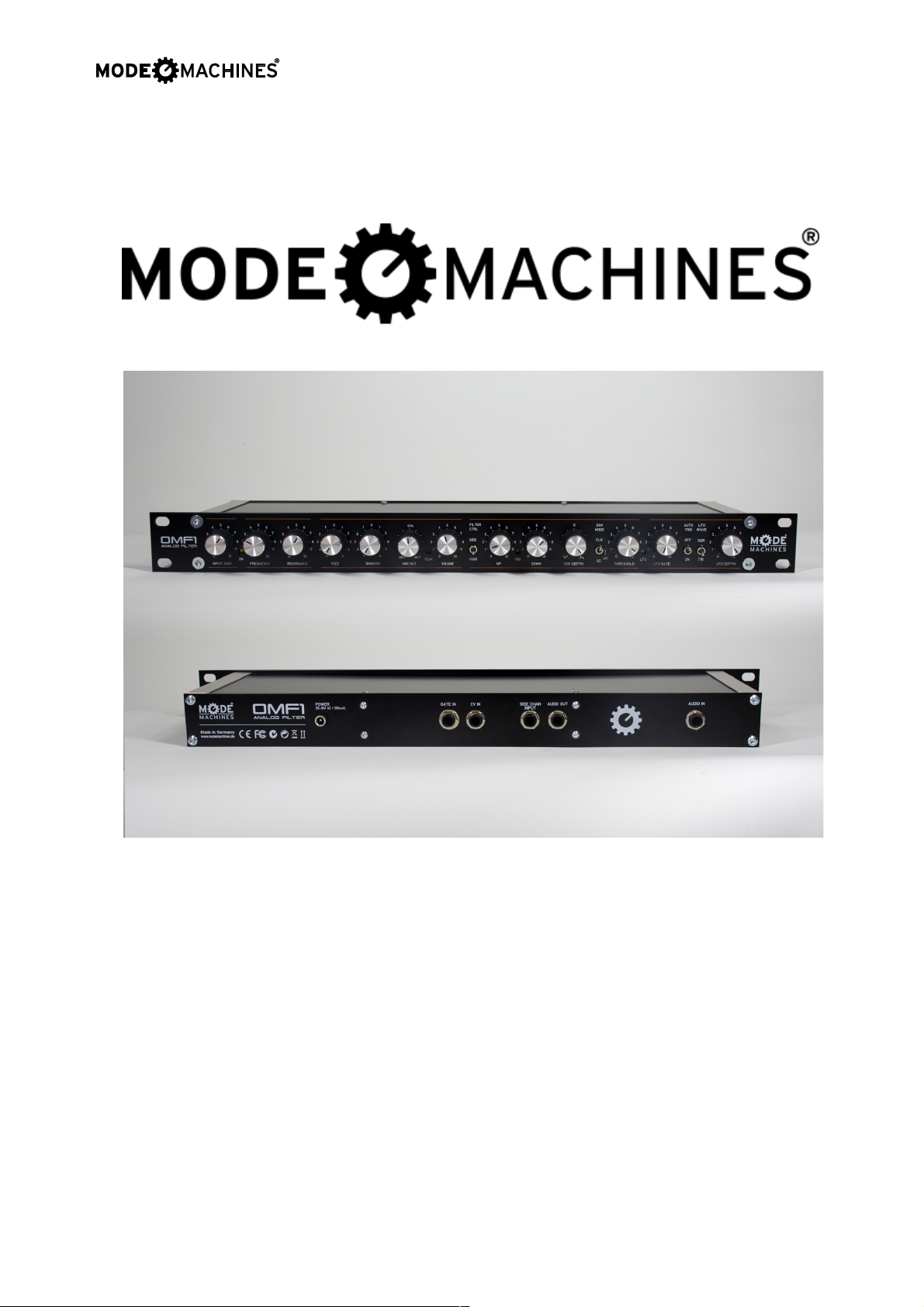
OMF-1
Analog filter Rack
OMF-1
Analogue Filter Rack
User Manual 2015
Written by:
Tony Allgood
Oakley Sound Systems
Carlisle
United Kingdom
www.modemachines.com
1
Page 2

OMF-1
Analog filter Rack
Overview of the OMF-1
The complete filter rack module contains:
A four pole true analogue filter. This is based on the famous transistor ladder filter
developed by Dr Bob Moog in the 1960s. A front panel pot controls the filter cut-off
frequency, another controls the resonance. The resonance control is configured not to
cause volume drop when turned up. The filter can be made to oscillate if required.
Two filter outputs are available. One is the Fizz output. This is a type of -6dB/octave filter
and it gives a unique filtering effect with a real bite. The other is the Smooth output. This is a
classic -24dB/octave filter, and gives a smooth warm analogue filter sound. Each output
goes via its own reversible attenuator. This means not only can you adjust the output level,
but also the phase of the output signal. This allows complex filter types to be made when
the two outputs are mixed together in various degrees.
A wide range single ended pre-amplifier is included. You can use the OMF-1 with virtually
any input from guitars to synthesisers. A peak indicator will allow you to monitor overloads,
although the OMF-1 is designed to overdrive beautifully.
An inbuilt low frequency oscillator with triangle and square waveforms. The frequency can
be changed from 0.2Hz to over 40Hz. A LED gives visual indication of the speed of the LFO.
Use this to create auto wah, vibrato and phaser type effects.
An ingenious dynamic envelope section that can move the filter cut off point up or down
automatically. It can be put into one of three modes at a flick of a switch:
FLR It can function as a useful envelope follower, with controllable attack and decay
times. Perfect for simulating many classic dynamic follower filter boxes. Play louder
and hear the filter open up.
AR It can be a standard attack-release envelope generator. This is triggered either by
the LFO, external gate signal or by an automatic audio trigger circuit with a
variable threshold level. Powerful for creating rising crescendos.
AD It can be a standard attack-decay envelope generator. This is a type of one shot
envelope, that rises and falls at the presence of an initial trigger signal. Useful for
percussive type sounds.
The output level can be controlled with a master volume control. The output circuitry is
configured to drive long length cables with ease and offers a ground compensating facility to
reduce the likelihood of ground loops.
A side chain input is available. This is a second audio input that can control the main input,
but is not heard directly. Use this to trigger the envelope generator, or drive the envelope
follower. A common use of this is to make the main audio program respond to a drum
machine's output for syncopated effects. Use a deep rich string patch as your main input,
and listen to the drum machine automatically pulse the output to the beat.
www.modemachines.com
2
Page 3

OMF-1
Analog filter Rack
CV and gate inputs are available for connection to a modular synth or midi-CV converser.
The CV input will control the filter frequency, and the gate control will trigger the envelope
generator if selected.
The board is designed to be powered by an external AC supply of 15 to 22V rms.
What all those front panel controls actually do...
The PCB has thirteen rotary pots and four toggle switches to control the filter.
The first set of pots seen on the left up to the first switch are in the main audio pathway.
These pots will directly control what you hear from the main output. The pots and switches
to the right of these are the controllers. They do not control the audio direct but control
voltages or currents in the processor to affect the audio by controlling the filter’s cut-off
point.
Let us first look at the main audio control pots:
• Gain: Input level. This controls the level of the input audio signal to the filter. The
design features a fully active pre-amp with variable gain. Use this in conjunction with
the peak LED to obtain the best sound quality.
The voltage gain of the pre-amplifier stage can be varied from 0.4 to 122. A gain of
0.4 means that the output of the pre-amp is only 40% of the input level. While a gain of 122
means that the output level is 122 times bigger than the input. In audio circles this would
normally defined in dB. This pre-amplifier will give you a gain from -8dB to +42dB.
• On: This is the power on light. It will be on if the power supply is switched on.
• Frequency: Manual control of filter cut-off frequency. Covers the whole audio range.
Fully clockwise opens the filter and allows all signals to go through. Fully counter
clockwise will filter virtually everything and very little audio will get through the filter.
• Resonance: Resonance or emphasis. Controls the Q of the filter. Fully clockwise the
filter will oscillate at the cut off frequency. Not always desired... but can be useful
sometimes. There is a trimmer on the circuit board inside, called TRIM, that will
control the point at which oscillation occurs. It can be set so that oscillation will not
occur at all.
This control allows emphasis of the cut-off frequency. Although the filter is
generally thought of as cutting frequencies above a certain point, this pot
allows you to accentuate a narrow band of frequencies. The leads to very
distinctive ‘electronic’ sounds.
Note that this version of the ladder filter will not oscillate at very low
frequencies even if the TRIM and Resonance controls are set to their maximum
positions.
• Fizz: Output level of the one pole filter output. This is a reversible attenuator. The
pot is at its minimum position when pointing straight up. Fully clockwise allows the
www.modemachines.com
3
Page 4

OMF-1
Analog filter Rack
signal to be at full strength with no inversion of the signal. Fully counter clockwise
allows the signal to be at full strength but with inverted properties. The two types
actually sound identical on their own, but when mixed with the other two outputs
strange new filter sounds can be made.
• Smooth: Output level of the four pole filter output. As with FIZZ, this is a reversible
attenuator.
• Mix Out: Controls the wet/dry mix. That is it adjusts the ratio between the pre-
amplifier output and the output of the combined smooth and fizz signals. Set the Mix
Out pot to 'wet' to hear just the output of the filter. Set the pot to 'dry' to hear just the
output of the pre-amplified input signal with no filtering.
The Fizz, Smooth and Mix Out pots control the audio signal, and it will take a little bit of
practice to understand how these controls affect the final output signal. When each is used
on its own, the results are predictable enough. They act a simple level controls. However, by
mixing the signals together new and interesting effects can be heard. The simplest one to
try is setting the Mix Out to ‘wet’, the Smooth to full ‘+’ and the Fizz to full ‘-’. This creates a
simple band pass effect. What you will have here is not the traditional low pass filter sound,
but just one band of enhanced frequencies. You can sweep these up and down manually
with the filter frequency pot, or let the OMF do it all automatically with its many modulation
routes. At increased resonance, the output can become nothing like the original input signal.
• Peak: This LED glows fiery red when the filter starts to clip. However, the ladder filter
actually sounds very good when over-driven, so this may be what you want.
Generally the GAIN pot should be set so that this LED just flickers occasionally when
in normal operation. For over-driven sounds it is usually best to stick with simple
monophonic input signals. Playing complex chords through an overloaded filter can
produce some very harsh sounds.
• Output: The final output level is controlled by this pot. In normal use this pot would
normally be around the 1 o’clock position. However, this can be turned up to
give extra gain if you need it.
You should note that the peak LED only monitors the level going into the filter core
circuitry. It does not monitor the output of the module itself. The OMF's output
amplifier is designed to have an extra +10dB or so of gain. This allows for more
flexibility but it does mean that it is possible to overload and clip the output stage at
more extreme settings. This can be a useful source of new sounds but it can also
lead unwanted distortion. If the OMF sounds distorted and the peak LED is not lit
then you may need to back off the output level pot.
That completes the description of the audio controls at this stage. The rest of the pots and
switches control the envelope and low frequency oscillators. These form part of the control
circuitry and these will be described now.
• Control: This is a simple two way switch that allows the filter’s processing circuitry to
be controlled by the main input or a second input, sometimes called the ‘side chain’.
The side chain input is never heard directly from the main output, but when selected
it will be able to control the envelope generator or follower.
www.modemachines.com
4
Page 5

OMF-1
Analog filter Rack
• Up: Controls the speed at which the envelope generator or follower ramps upwards
to its maximum output value.
• Down: Controls the speed at which the envelope level falls from its maximum value
back to zero.
• Env Depth: This controls the amount that the envelope output controls the cut-off
frequency of the filter. It is a reversible attenuator, so straight up produces no
modulation, and therefore no movement of the filter frequency. Fully clockwise will
produce rising cut-off frequencies. Fully anti-clockwise will produce falling cut-off
frequencies.
• Mode: This is a three position switch and its simple function hides some quite clever
circuitry behind it. It controls the mode of the envelope section and can be set to FLR
(follower), AR (attack-release) and AD (attack-decay).
The follower mode is similar to the envelope follower filters like the Mutron and Doctor-Q
guitar stomp boxes of the past. Simply put, the input is analysed for volume, the louder the
volume of the incoming signal, the bigger the envelope follower’s output. This essentially
means that loud sounds will move the filter frequency more than quiet sounds.
The key to a good follower is the speed at which it reacts to the input signal. In the OMF, the
‘up’ control determines the speed at which the follower’s output voltage rises. Set this to its
maximum value and the envelope output will slowly rise when the signal is present. Set to
the minimum value, the output will rise very quickly indeed. The ‘down’ control affects the
speed of which the output falls once the input signal is no longer there. Getting the ‘down’
time right will be crucial in getting the sound that you need. Set this too fast, and you will
hear an odd stuttering from the filter. Set it too long and the envelope output won’t shut
down fast enough to respond to the changes in the music. The actual correct setting of
these two pots is determined by the music material you are putting into the OMF and the
sound you require. Experimentation will lead you to learning how this important section
works.
Both the AR and AD modes refer to the operation of the envelope generator or EG for short.
This is similar in some ways to the operation of the follower, but different in one major thing.
It is not the audio input that controls the EG circuitry but a gate signal. A gate signal is either
on or off. Remember an audio signal is a true analogue signal and can be many values, not
just the two extremes of on and off.
The gate signal is derived from several sources; the LFO, the threshold detector and the
external gate input. Each of these will discussed in detail later on, but for now, we will
consider just the operation of the EG.
When a gate signal is received from any of the three sources, the attack mode is started.
This means the output of the EG will rise from zero to a fixed peak value. The time taken to
reach this peak value is determined by the ‘up’ control. If the gate is removed at any point
during this phase the release phase begins and the output falls. The speed at which the
output falls is controlled by the ‘down’ pot. Assuming the gate signal does stay high, and the
peak signal is reached, what happens next depends on the mode the EG is in.
www.modemachines.com
5
Page 6

OMF-1
Analog filter Rack
In the AR mode, the output will stay high as long as the gate is active high. In other words
the output is ‘sustained’. Once the gate is turned off and goes low, the output of the EG will
fall.
In the AD mode, the output of the EG will drop as soon as the peak is reached. There is no
sustain and the release mode is started prematurely even if the gate is still high. This
premature release mode is correctly called decay.
AR mode produces sustained effects like an organ. The AD mode produces percussive
sounds like a guitar or marimba.
• Threshold: The audio-trigger circuit. The peak level of the audio signal, either the
main input or the ‘side chain’, is analysed in this section. If the audio input is higher
than the level set by the threshold pot, then a gate output is produced that can trigger
the EG if turned on. With the pot set less than fully clockwise, a loud signal is
required to trigger the EG. With it set fully anti-clockwise very quiet sounds will trigger
it. However, setting it too low can cause false triggering. This pot's operation can get
some getting used to. Stick with this, the results are worth it.
The effects of the audio-trigger circuit can be turned off by simply setting the
threshold pot to its most clockwise position. No matter how loud your incoming
signal the audio-trigger circuit will not detect any audio with the pot in this position.
• LFO: This little bi-colour LED responds to the output of the LFO. It will gently pulse in
brightness and colour according to the speed of the LFO.
• LFO rate: Low frequency oscillator (LFO) frequency. Controls the frequency of the
LFO. From about 0.2Hz (slow) to 30Hz (fast). Great for producing ‘wah-wah’
and trancey swishes when the filter is set to self oscillate.
• Auto Trig: LFO trigger. The LFO will trigger the EG automatically. The Trig LED will
flash at the speed determined by the LFO frequency when this is turned on.
• LFO wave: This controls the waveform that will modulate the LFO via the LFO depth
control. Triangle or square wave outputs. Triangle will move the cut-off frequency up
and down smoothly, like wah-wah. Square wave will move the cut-off point rapidly
between two points, creating “bip-bip-bip” sounds.
• LFO depth: Controls the amount that the LFO can affect the filter.
That completes the overview of the front panel operation.
www.modemachines.com
6
Page 7

OMF-1
Analog filter Rack
Power Supply
The OMF-1 is supplied with the appropriate wall-wart AC adapter. In case you need a
replacement, you can get the correct AC Adapter for the OMF-1 through Mode Machines
online store:
https://supr.com/mode-machines/category/products/power-supplies/
In case you want to source your own power supply, the recommended option is to use an
insulated wall-wart or AC adapter. These can be bought from most places and are used
external to the OMF housing. They are very safe since all the nasty dangerous stuff is kept
inside the wall-wart.
You need a 15V or 18V alternating current (AC) output at 250mA or higher rating. Do not
use a DC output type. Although the latter are the most common type of wall-wart for guitar
effects pedals, they will not work with the OMF. To reiterate, because this is really important,
it must say 15VAC or 18VAC on it somewhere.
In the UK they can be bought from Maplin Electronics. The one we recommend is their part
number N57AT. This is a variable supply which means it can supply a variety of different
voltages. The adjustment is on the underside of the unit. Simply set this to 15V with a small
blade screwdriver.
Some 12V AC output types may also work but this is only because some AC output wallwarts tend to be poorly regulated and have a lot of overhead. Do be aware that if they do
work some of the time they may not work all of the time. If the voltage does fall below the
required operating voltage of the OMF-1 the most obvious sign is an audible hum from the
outputs. You will not damage the OMF-1 by doing this although any connected amplifier or
speaker system may object to the humming.
www.modemachines.com
7
Page 8

OMF-1
Analog filter Rack
A bit of history...
In 1998 the Oakley Sound Systems VCF-1 was my first PCB project to be released. It
proved to be a moderate success and paved the way for the development of a whole range
of PCB projects designed for the audio DIY hobbyist. After the very first strip-board
prototype, two printed circuit board issues were made. The first issue used Alps 16mm pots
and 30 boards were sold. The second issue corrected a few things and allowed the use of
the then popular Omeg P16 plastic pots and brackets. Just sixty issue 2 PCBs were sold.
In 2002 I decided to update the design and improve certain aspects of it that I thought could
be done better. Three things stood out as being key areas to improve.
1. The VCF-1 created smooth sweeps that warmed up any harsh digital sound. But it
couldn’t do the opposite. It couldn’t be nasty, well, not nasty enough anyway. Enter
the OMF’s one pole or Fizz output. This created a bright bubbly sound that had a
whole new character. If you then mixed that in with the ordinary four pole or smooth
output you would get a band pass response.
2. The envelope follower (EF) in the VCF-1 was quick responding and worked well with
most program material, especially keyboards and drums. But it didn’t sound right with
guitars. The problem was a decay time that was too fast. Experimenting with the
MOTM-820 lag processor and the Oakley EFG on a modular synthesiser allowed me
to try out various topologies. In the end I settled for a complex, yet simple to operate,
envelope follower with fully variable rise and fall times. This combines the functions of
an attack-decay/attack-release envelope generator (EG) with a controllable envelope
follower. Rise and fall times can now be set independently which made the OMF-1
more useful than its predecessor.
3. The lack of a bypass function on the VCF-1 made the unit difficult to use without a
mixing desk. The OMF-1’s Thru function allowed the ‘wet-dry’ level to be set.
Although in practice finding the control's middle null point was somewhat tricky. It did
however allow for complex filter responses. Mixing the filter’s output with the
unfiltered audio input interacts in such a way as to create new filter and phase
responses.
The last OMF-1 was sold in 2005. There had been a second issue of the PCB in 2004 but
this was to be the last run of boards for a while. However, repeated requests for the board to
be reinstated finally had their desired effect. The first issue of the OMF-1 rolled off the
production lines in November 2009.
The OMF-1 is more of a refinement of the design ideas introduced with the OMF-1 rather
than a totally new module. OMF-1 boards are different only in the following things:
1. Uses 16mm Alpha/ALPS pots instead of the Omeg P16 types.
2. The 'thru' reversible attenuator has been changed to a dry/wet pot. This gives you the
same functionality but makes it a lot easier to find 100% wet.
3. Uses the excellent THAT300P instead of the now obsolete SSM2210 NPN pairs.
4. Resonance can now be turned completely to zero.
5. Changed output driver circuitry.
6. The PCB's are blue instead of green.
www.modemachines.com
8
Page 9

OMF-1
Analog filter Rack
Final Comments
I hope you enjoy using the OMF-1.
For any questions or extra information, latest version of the Manual and other support files,
please visit www.modemachines.com or contact us directly at [email protected].
If you have any problems with the module, an excellent source of support is the Oakley
Sound Forum at Muffwiggler.com. Paul Darlow and I are on this group, as well as many
other users and builders of Oakley modules.
If you have a comment about this user guide, or have a found a mistake in it, then please do
let me know.
Last but not least, can I say a big thank you to all of you who helped and inspired me.
Thanks especially to all those nice people on the Muffwiggler's forum and the SynthDIY and
Analogue Heaven mailing lists
Tony Allgood at Oakley Sound
Cumbria, UK
© November 2009 updated August 2012
© Mode-Machines update November 2015
MODE MACHINES GmbH
Im Funkwerk 3
D-99625 KÖLLEDA
GERMANY
www.modemachines.com
9
 Loading...