

Page 1
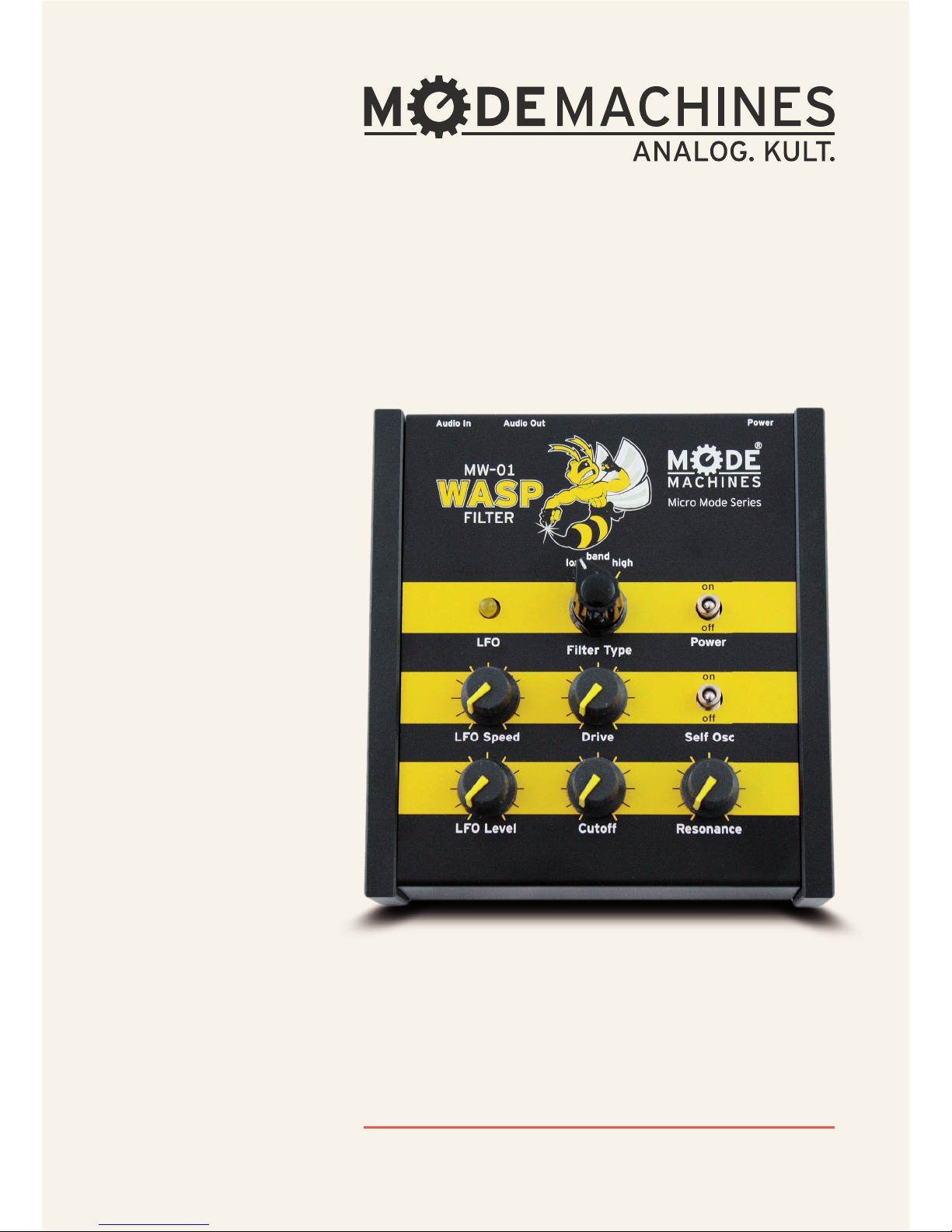
MW-01 WASP Filter
MANUAL
Page 2

PAGE 2
for purchasing the MODE MACHINES
MW-01 “WASP Filter”.
T
his fi lter is based on the circuitry of
the WASP Synthesizer built by “Elec-
tronic Dream Plant” (EDP) in the late 70‘s.
Apart from its own distinctive sound its
three diff erent fi lter types set it apart
from other fi lters.
While the original circuit did not self os-
cillate with high Resonance settings the
MW-01 features a switch that will allow
self oscillation under certain circum-
stances to occur.
THANK YOU
Page 3
PAGE 3
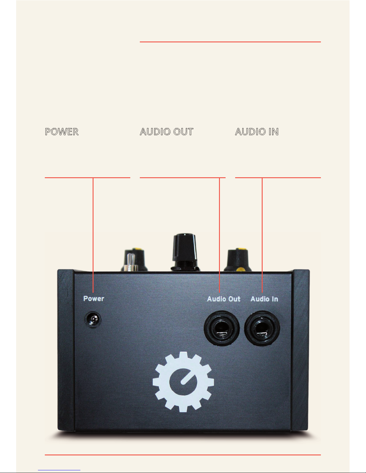
CONNECTIONS
POWER
9 - 12V DC input with
“+” on center pin
AUDIO OUT
Audio input:
6.35mm mono jack
AUDIO IN
Audio output:
6.35mm mono jack
Page 4
PAGE 4
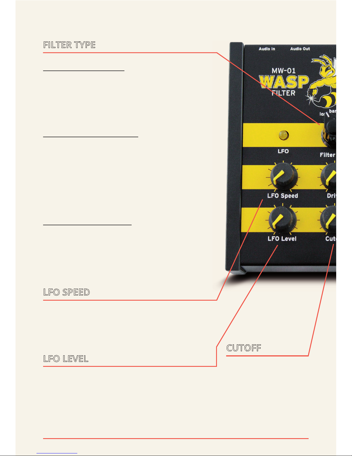
LFO LEVEL
This control determines how strong the
LFO modulates the Cutoff frequency.
Turning the knob clockwise will increasingly move the fi lter frequency up and
down periodically.
FILTER TYPE
low: low pass fi lter.
Turning the “Cutoff ” control counterclockwise will attenuate high frequencies. The low pass fi lter is the most commonly found fi lter in synthesizers.
band: band pass fi lter.
A band pass fi lter will - as the name suggests - let pass only a certain frequency
range; frequencies both higher and lower outside this range will be attenuated.
The “Cutoff ” knob controls the middle frequency of this range.
high: high pass fi lter.
Turning the “Cutoff ” control clockwise
will attenuate lower frequencies so that
only the high frequency components of
the signal remain audible.
LFO SPEED
This knob controls the speed of the LFO
(“Low Frequency Oscillator”). The speed is
also indicated by the LED above.
CUTOFF
The “Cutoff ” knob
controls the fi lter
frequency. The result depends also
on the “Filter Type”
setting.
Page 5
PAGE 5
FUNCTIONS
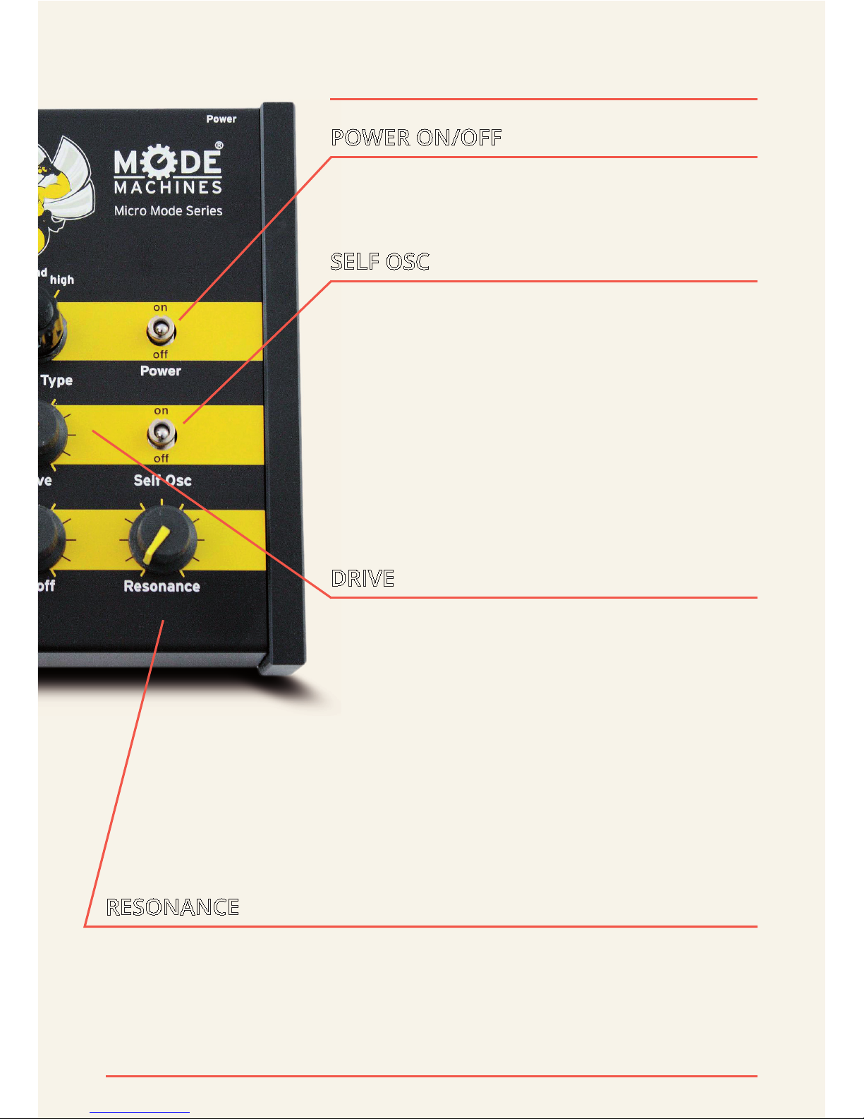
DRIVE
This knob controls the pre-amplifi cation
of the signal prior to entering the actual
fi lter circuit. At minimum setting there’s
no additional amplifi cation. Turning
the “Drive” control clockwise grdually
increases the signal’s amplitude until it
starts to distort. The amount of distortion also depends on the original amplitude of the signal.
SELF OSC
This switch modifi es the fi lter circuit to enable the fi lter so self oscillate at high “Resonance” settings. The fi lter will then generate
a sine by itself. The frequency of the sine is
controlled by the “Cutoff ” knob.
Depending on the “Filter Type” setting it
may be necessary to open the “Drive” control for self oscillation actually to happen.
POWER ON/OFF
Turns the unit on/off .
RESONANCE
This control feeds a certain amount of the fi ltered signal
back to the fi lter input. This will emphasize the Cutoff frequency. If “Self Osc” is active this control can make the fi lter
generate its own sine signal.
Page 6

For information, pictures and accessories to our product line, please visit:
www.modemachines.com
Information, product news and many
other interesting articles can be found at
www.facebook.com/modemachines
You also get news and links from Twitter.
Follow us on
www.twitter.com/modemachines
Mode Machines is a Division of Michael
Thorpe Consulting GmbH
Fichtenstraße 49 • 90763 Fürth • Germany
CONTACT
© 2013 MODE MACHINES. All rights reserved.
 Loading...