

Page 1
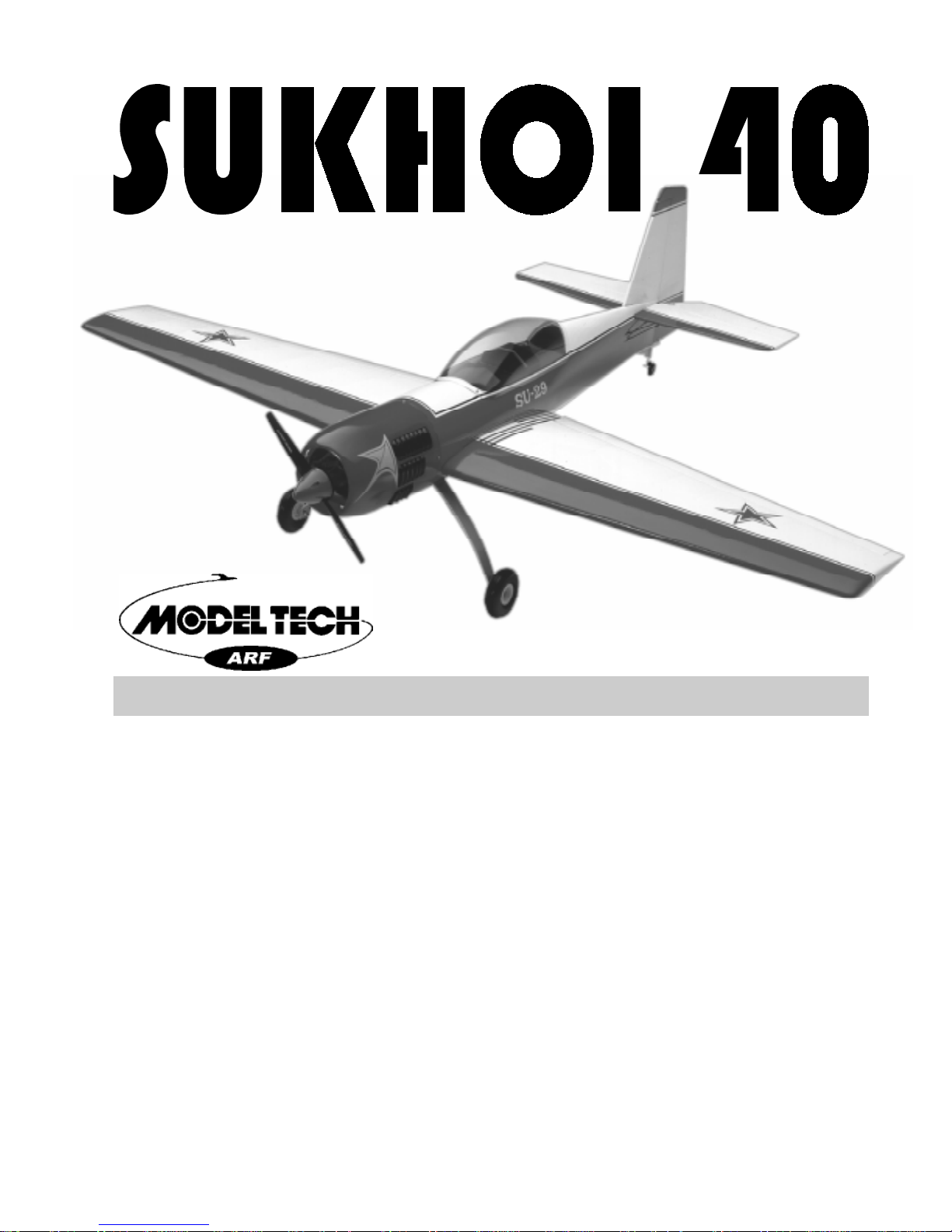
40 - 46 Size Almost Ready to Fly
Instructions for Final Assembly
Sukhoi is synonymous with performance. From high performance military aircraft like
the Su-27 to the aerobatic flagship Su-31, airshow spectators all over the world have
witnessed exciting, cutting edge performance by aircraft bearing the Sukhoi name. The
Su-26 put Sukhoi on the map for performance Russian aircraft. Later versions such as the
Su-31 continue to awe and inspire flight hungry folks today. But unlike its single place
counterparts, the Su-29, with its power and almost frightening roll rate is one of the few
aerobatic aircraft made for two passengers. The longer canopy and much less curved
landing gear give the Su-29 a very unique look. In modeling, the Su-29 is very rare
indeed. It is not the cliche of the field. This Sukhoi is no slouch either. Great power to
weight ratio and a light wing loading make this ARF a true high performance 40 class
aircraft. The Modeltech Su-29 ARF was developed for modelers, by modelers. The fiber-
glass cowling, preformed aluminum landing gear and fully adjustable tail wheel assem-
bly are just a few examples of the high quality that will give your Sukhoi longevity that no
"plastic" ARF plane can provide. An all wood airframe covered with iron-on polyester
covering means maintenance and repairs are now possible. Its built with the same quali-
ties hobbyists want in any kit they would build themselves. From all of us at Modeltech,
please enjoy!
Version V1.0 5-99 Kit # 123668 All Contents © Copyright 1999
1
Page 2

TABLE OF CONTENTS
Kit Contents...................................................2
Additional Items Required................................3
Tools and Supplied Needed..............................3
Field Support Equipment Needed......................3
Metric Conversion Chart.................................3
Wing Assembly...............................................4
Install the Dihedral Brace..........................4
Joining the Wing Halves............................5
Wing Mounting...............................................5
Align the Wing..........................................5
Installing the Blind Nuts.............................6
Installing the Wing Bolt Doubler.................6
Installing the Wing.....................................6
Belly Pan Installation.......................................6
Installing the Mounting Blocks....................6
Installing the Triangle Supports...................7
Aligning the Belly Pan...............................7
Installing the Belly Pan..............................8
Horizontal Stabilizer Mounting..........................8
Align the Horizontal Stabilizer.....................8
Mounting the Horizontal Stabilizer ...............9
Vertical Stabilizer Mounting..............................9
Align the Vertical Stabilizer........................9
Mounting the Vertical Stabilizer.................10
Control Surface Installation............................10
Hinge the Ailerons...................................10
Hinge the Elevator Halves.......................10
Hinge the Rudder....................................10
Tail Wheel Installation....................................11
Tail Wheel Bracket Assembly...................11
Installing the Tail Wheel...........................11
Mounting the Tail Wheel Bracket.............12
Main Landing Gear........................................12
Installing the Gear Bracket.......................12
Installing the Gear Cover..........................13
Installing the Main Gear Wheels...............13
Engine Mounting...........................................14
Mounting Engine to Motor Mount.............14
Aligning the Motor Mount........................14
Mounting the Engine to Firewall...............15
Fuel Tank......................................................15
Fuel Tank Assembly................................15
Fuel Tank Installation...............................16
Throttle Linkage............................................16
Installing the Throttle Linkage..................16
Servo Installation...........................................16
Installing the Fuselage Servos...................16
Installing the Servo Tray...........................17
Installing the Aileron Servo......................17
Throttle Connector.........................................18
Installing the Throttle Connector...............18
Rudder Pushrod............................................18
Installing the Rudder Control Horn............18
Rudder Pushrod Assembly.......................19
Rudder Pushrod Installation......................19
Elevator Pushrod...........................................20
Installing the Elevator Control Horns........20
Elevator Pushrod Assembly......................21
Elevator Pushrod Installation....................21
Aileron Linkage............................................22
Installing the Aileron Linkage...................22
Cowl Installation...........................................23
Installing the Cowl Vents.........................23
Installing the Cowl...................................23
Canopy Installation........................................24
Installing the Instrument Panels................24
Installing the Canopy................................25
Decal Application.........................................25
Applying the Decals................................25
Final Assembly.............................................25
Installing the Receiver and Battery...........25
Installing the Switch................................26
Balance.......................................................26
Lateral Balance......................................26
Control Throws.............................................26
Flight Preparation..........................................27
Preflight Check.......................................27
Flying...........................................................28
Notes...........................................................28
Trim Chart....................................................29
Product Evaluation........................................30
Modeltech guarantees this kit to be free from defects in both material and workmanship, at the date of purchase. This
does not cover any components parts damaged by use, misuse or modification. In no case shall Modeltech's liability
exceed the original cost of the purchased kit.
In that Modeltech has no control over the final assembly or material used for final assembly , no liability shall be assumed
for any damage resulting from the use by the user of the final user-assembled product. By the act of using the final userassembled product, the user accepts all resulting liability .
T o make your modeling experience totally enjoyable, we recommend that you get experienced, knowledgable help
with assembly and during your first flights. Your local hobby shop has information about flying clubs in your area
whose membership includes qualified instructors. You can also contact the AMA at the address below.
Academy of Model Aeronautics
5151 East Memorial Drive
Muncie, IN. 47302-9252
(800) 435-9262
www.modelaircraft.or g
2
Page 3

This instruction manual is designed to help you build a straight, great flying airplane. Please read this
manual thoroughly before beginning assembly of your new Sukhoi. Use the parts listing below to identify
and separate all parts before beginning assembly .
** KIT CONTENTS** W e have organized the parts as they come out of the box for better identification
during assembly . W e recommend you regroup the parts in the same manner. This will ensure you have all
of the parts required before you begin assembly and will also help you familiarize yourself with each part.
KIT CONTENTS
AIRFRAME ASSEMBLIES
o {2} Wing Halves w/Ailerons and Hinges
o {1} Fuselage
o {1} Horizontal Stabilizer w/Elevator Halves and Hinges
o {1} V ertical Stabilizer w/Rudder and Hinges
o { 1 } Clear Molded Canopy
o { 1 } Molded Fiberglass Cowl
o { 2 } Plastic Molded Cowl V ent Sets
o { 1 } Molded Fiberglass Belly Pan
o { 1 } Molded Fiberglass Gear Cover
MAIN GEAR ASSEMBL Y
o { 1} Aluminum Main Gear Strut
o {4 } 4mm x 12mm Machine Screws
o {8 } 4mm Flat Washers
o {4 } 4mm Blind Nuts
o {2} 4mm x 30mm Axle Screws
o {4 } 4mm Nylon Insert Nuts
o { 2 } Nylon Axle Spacers
o { 2} 76mm Diameter Wheels
o {2 } 3mm x 15mm Machine Screws
o {2 } 3mm Flat Washers
TAIL WHEEL ASSEMBL Y
o {1 } Nylon Tiller Arm
o {1 } Nylon Tail Wheel Bracket
o {1 } 25mm Diameter Wheel
o {1 } Tail Wheel Wire
o {2 } Wheel Collars w/3mm x 6mm Machine Screws
o {3 } 3mm x 12mm Wood Screws
o {1} 2.5mm x 10mm Wood Screw
ELEV A T OR CONTROL SYSTEM
o {1 } W ood Dowel (D-34)
o {1 } 2mm x 90mm Wire w/L-Bends Both Ends
o {2 } 2mm x 210mm Wire Threaded One End
o {2 } Nylon Clevis w/2mm I.D. Hole
o {1} Nylon Snap Keeper
o { 2 } Nylon Control Horns (small)
o { 2} Nylon Control Horn Backplates (small)
o {4 } 2mm x 15mm Machine Screws
THROTTLE CONTROL SYSTEM
o {1 } 2mm x 300mm Pushrod Wire w/Z-Bend
o {1} Adjustable Servo Connector Assembly
RUDDER CONTROL SYSTEM
o {1 } Wood Dowel (D-34)
o {1 } 2mm x 90mm Wire w/L-Bends Both Ends
o {1 } 2mm x 210mm Wire Threaded One End
o {1 } Nylon Clevis w/2mm I.D. Hole
o {1} Nylon Snap Keeper
o { 1 } Nylon Control Horn (large)
o { 1} Nylon Control Horn Backplate (large)
o {2 } 2mm x 15mm Machine Screws
AILERON CONTROL SYSTEM
o {2 } Nylon Clevises w/2mm I.D. Hole
o {2 } 2mm x 138mm Threaded Rod w/L-Bend
o {2} Nylon Snap Keepers
o {2} Nylon Adjustable Control Horns
MOTOR MOUNT ASSEMBLY
o {2} Nylon Motor Mount Beams
o {4 } 3mm x 25mm Machine Screws
o {4} 3mm x 20mm Machine Screws
o {4 } 3mm Nylon Insert Nuts
o { 4} 3mm Blind Nuts
o {12} 3mm Flat W ashers
MISCELLANEOUS ITEMS
o { 1} Plywood W ing Dihedral Brace (W-36)
o { 1} Gear Cover Mounting Block (D-31)
o { 4} Belly Pan Mounting Blocks (D-32)
o { 2} Balsa Triangle Supports (D-33)
o { 2 } Aileron Servo Mounting Plates (W-37)
o { 1 } Fuselage Servo Tray (D-10)
o { 1} Plywood Wing Bolt Doubler (W-39)
o { 2} Plastic Molded Instrument Panels
o {1} Plastic Molded Spinner Assembly
o {2 } 3mm x 18mm Wood Screws
o {2} 5mm x 30mm Machine Screws
o {2 } 5mm Flat Washers
o {2 } 5mm Blind Nuts
o {4 } 2mm x 10mm Wood Screws
o {4} 2mm x 6mm Wood Screws
o {1 } Decal Set
FUEL T ANK
o {1 } Molded Fuel T ank
o { 1 } 20mm Front Squash Plate
o { 1} 18mm Rear Squash Plate
o { 1} Rubber Stopper
o {1 } 70mm Length of Fuel Tubing
o { 1 } Metal Weighted Pick-Up
o { 3 ) Aluminum Tubes
o {1 } 3mm x 20mm Machine Screw
3
Page 4

ADDITIONAL ITEMS REQUIRED
o {1}Hitec 4 or More Channel Radio w/4 Servos
o {1}Dubro Foam Rubber # 513
o {1}Global Fuel Line # 115923
o {1}Dubro Fuel Filling V alve # 334
o {1}Goldberg 1/2A Flying Line # 431
o {1}Topflite Gloss Clear Spray # TOPR7200
OPTIONAL ITEMS
o {2}Williams Bros. 2-5/8” Pilots # 18500
o {1}Ernst Charge Jack # 124
o {1}Cirrus On-Board Battery Indicator # 444762
o {1}Magnum 2” Aluminum Spinner # 237152
o {1}Goldberg 1/4” White Trim T ape # 724
o {1}Goldberg 1/4” Red Trim T ape # 723
o {1}Goldberg 1/8” Black Trim T ape # 71 1
TOOLS AND SUPPLIES NEEDED
o Kwik Bond Thin C/A # 887500
o Kwik Bond Thick C/A # 887510
o Kwik Bond 5 Minute Epoxy # 887560
o Kwik Bond 30 Minute Epoxy # 887565
o Wilhold Silicon Sealer # 00684
o Pacer RC256 Canopy Glue # PT-56
o Electric Drill
o Assorted Drill Bits
o Modeling Knife
o Machine Oil or V aseline
FOR 2-STROKE ENGINE
o {1}Magnum XL .40-.46 Two Stroke
o {1}Propeller T o Suit Engine
o {1}Thunderbolt Glow Plug # 115493
o {1}Slim Line Pitt's Style Muffler # 3218
FOR 4-STROKE ENGINE
o {1}Magnum XL .52RFS Four Stroke
o {1}Propeller T o Suit Engine
o {1}Thunderbolt Glow Plug # 115490
o Straight Edge Ruler
o Dremel Tool w/Assorted Bits
o Phillips Screwdriver
o Z-Bend Pliers
o Builders Triangle
o 220 Grit Sandpaper
o Masking T ape
o Paper T owels
o Rubbing Alcohol
o Wire Cutters
FIELD SUPPORT EQUIPMENT NEEDED
o Magnum 12V Electric Starter (# 361006)
o Magnum 12V Fuel Pump (# 237377)
o Magnum Locking Glow Clip (# 237440)
o Global 12V Battery (# 110171 )
METRIC CONVERSION CHART
T o convert inches into millimeters: Inches x 25.4 = MM
1/64” = .4mm
1/32” = .8mm
1/16” = 1.6mm
3/32” = 2.4mm
1/8” = 3.2mm
5/32” = 4.0mm
3/16” = 4.8mm
1/4” = 6.4mm
3/8” = 9.5mm
1/2” = 12.7mm
5/8” = 15.9mm
3/4” = 19.0mm
o Global 12V Charger (# 110270 )
o Magnum Power Panel (# 237390)
o Global Field Buddy Flight Box (# 233072)
o Magnum 4-Way Wrench (# 237420)
1 ” = 25.4mm
2 ” = 50.8mm
3 ” = 76.2mm
6 ” = 152.4mm
12 ” = 304.8mm
18 ” = 457.2mm
4
21 ” = 533.4mm
24 ” = 609.6mm
30 ” = 762.0mm
36 ” = 914.4mm
Page 5
If you should find a part missing or have questions about assembly , please call or write to the address below:
Customer Service Center
18480 Bandilier Circle
Fountain V alley , CA. 92728
Phone: (714) 963-0329
Fax: (714) 964-6236
E-Mail: [email protected]
**SUGGESTION** To avoid scratching your new airplane, do not unwrap the pieces until they are
needed for assembly . Cover your workbench with an old towel or brown paper , both to protect the aircraft
and to protect the table. Keep a couple of jars or bowls handy to hold the small parts after you open the
bags.
**NOTE** Please trial fit all the parts. Make sure you have the correct parts and that they fit and are
aligned properly before gluing! This will assure proper assembly. Since the Sukhoi is hand made from
natural materials, every plane is unique and minor adjustments may have to be made. However, you
should find the fit superior and assembly simple.
WING ASSEMBLY
PARTS REQUIRED
o {2} Wing Halves w/Ailerons and Hinges
o {1 } Plywood Wing Dihedral Brace (W-36)
INSTALL THE DIHEDRAL BRACE
o 1) Look at the face of each root rib on both
wing halves. Notice how the excess covering material overlaps onto them. Using a modeling knife,
carefully cut away the covering from both of the
root ribs. Leave about 1/16” of covering overlapping so it does not pull away .
It is important that the covering be removed
from the root ribs. This will ensure an adequate wood-to-wood glue joint and prevent
wing failure during flight.
o 2) Using a ruler and a pen, locate and
mark the centerline of the wing dihedral brace
(W-36). Draw a vertical line at this location
on each side. See photo # 1 below.
Photo # 1
DRAW CENTERLINE
DIHEDRAL BRACE
o 3) T est fit the dihedral brace into the plywood box in each wing half. The brace should
slide into each wing half up to the centerline. If it
does not, remove the brace and lightly sand the
edges and tips until the proper fit is obtained. See
photo # 2 below.
Photo # 2
DIHEDRAL
BRACE
The dihedral brace is cut in the shape of a
"V" on the bottom and is flat on the top. It
should be installed with the flat side facing the top
of the wing to form the proper dihedral angle when
the wing halves are joined.
o 4) Test fit both of the wing halves together
with the dihedral brace temporarily installed. Do
not glue it in at this time! The wing halves should
fit together tightly with little or no gaps in the center
section joint. If the center section joint is not tight,
remove the wing halves and lightly sand the edges
and tips of the dihedral brace. Reinstall the wing
halves and brace and test the fit until you are satisfied with the fit of the wing halves.
o 5) When satisfied with the fit of the wing
halves, remove the halves and the dihedral brace.
5
Page 6
JOINING THE WING HAL VES
o 6) Mix a generous amount of Kwik Bond
30 Minute Epoxy . W orking with only one wing
half for now , apply a thin layer of epoxy inside the
plywood dihedral brace box and on only half of
the dihedral brace. Make sure to cover the top
and bottom as well as the sides and use enough
epoxy to fill any gaps.
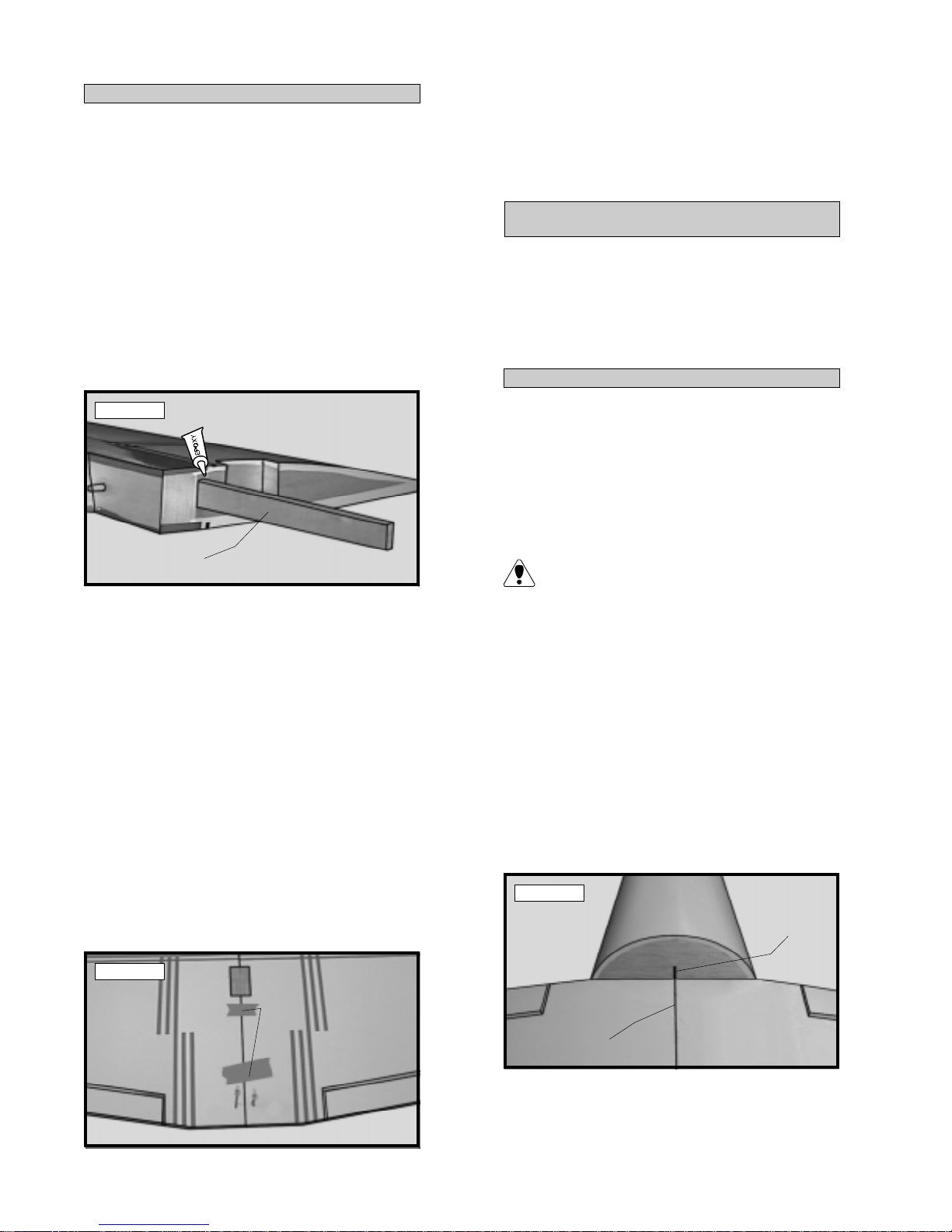
o 7) Slide the dihedral brace into the plywood
box up to the centerline. Remove any excess
epoxy before it dries using a paper towel and rubbing alcohol. Allow the epoxy to cure before
proceeding. See photo # 3 below.
o 11) When the epoxy has cured, double
check the center section joint. If any gaps are
present, mix a small amount of Kwik Bond 30
Minute Epoxy and carefully fill any remaining gaps.
Allow the epoxy to fully cure before proceeding.
WING MOUNTING
PARTS REQUIRED
o {1} Wing w/Ailerons & Hinges
o { 1 } Plywood Wing Bolt Doubler (W-39)
o {2 } 5mm x 30mm Machine Screws
o {2 } 5mm Flat Washers
o {2 } 5mm Blind Nuts
ALIGN THE WING
Photo # 3
DIHEDRAL
BRACE
o 8) Once the epoxy has cured, trial fit both
wing halves together to double check that the wing
halves still fit correctly .
o 9) Mix a generous amount of Kwik Bond 30
Minute Epoxy . Apply a thin layer of epoxy to the
exposed half of the dihedral brace, the inside of
the plywood box in the second wing half and the
entire surface of both root ribs. Make sure to
use enough epoxy to fill any gaps.
o 10) Slide the two wing halves together and
carefully align them at the leading and trailing edges.
Wipe away any excess epoxy using a paper towel
and rubbing alcohol. Use masking tape to hold the
wing halves in place until the epoxy cures. See
photo # 4 below .
o 1) Place the wing into the wing saddle making sure that the two preinstalled dowels in the leading edge of the wing fully engage the predrilled holes
in the forward bulkhead in the fuselage. Push the
wing as far forward as possible. The leading edge
should fit tight against the bulkhead.
It may be necessary to sand the forward
section of the wing to fit the fuselage sides.
If so, use 220 grit sandpaper.
o 2) Using a ruler and a pen, measure and
place a mark on the centerline of the bottom of
the fuselage at the rear of the wing saddle. Also
measure and place a mark at the centerline of the
wing at the trailing edge.
o 3) With the wing in the wing saddle, align
the two centerline marks and hold the wing
securely in place using a couple of pieces of
masking tape. See photo # 5 below .
Photo # 5
FUSELAGE
CENTERLINE
Photo # 4
MASKING
TAPE
WING
CENTERLINE
6
Page 7
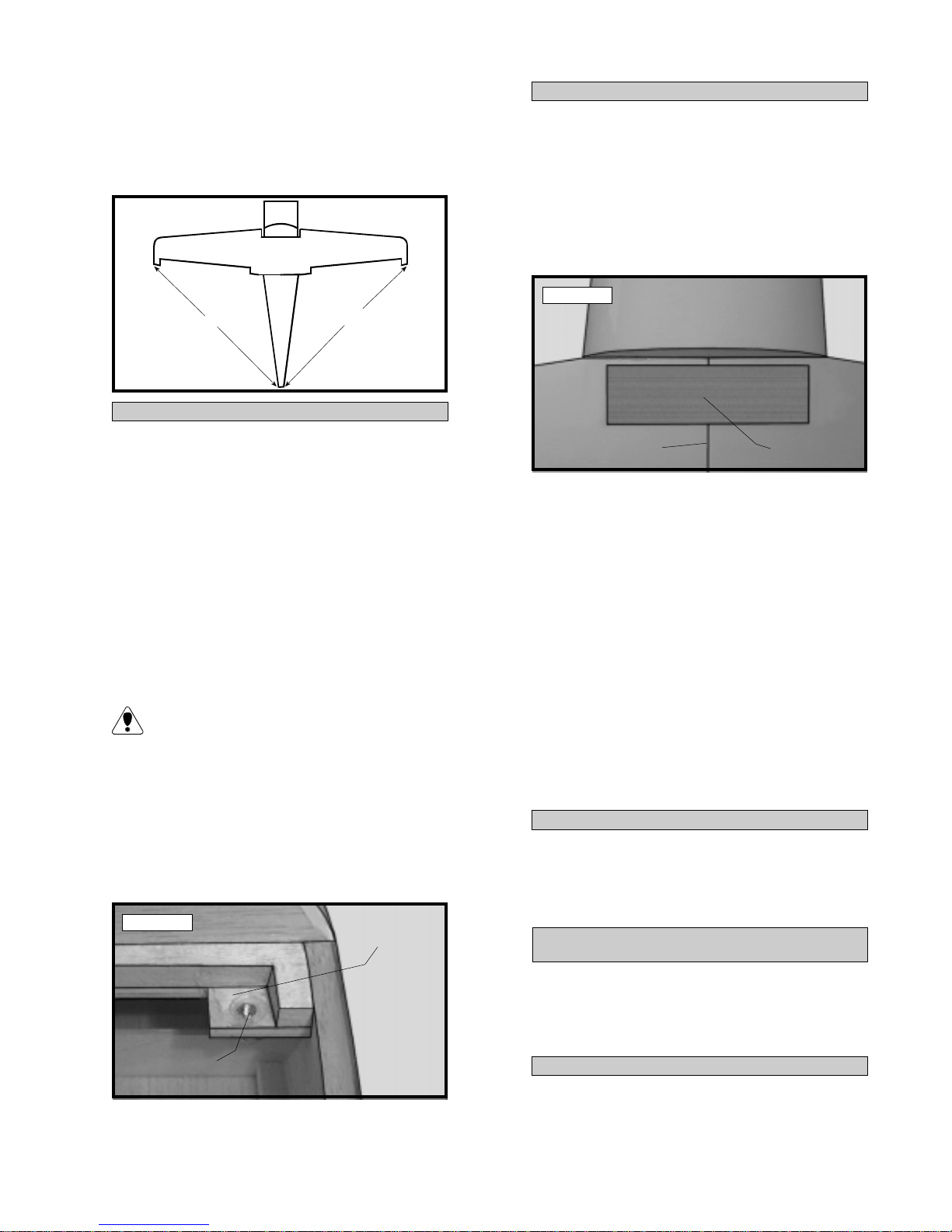
o 4) Remove the ailerons from the wing. To
double check that the wing is square to the fuselage, use a ruler and measure from each wing tip
to the rear edge of the fuselage. Both measurements should be equal. See figure # 1 below .
Figure # 1
A
INST ALLING THE BLIND NUTS
A1
INST ALLING THE WING BOLT DOUBLER
o 8) Place the wing back into the wing
saddle, aligning the centerline marks. While
holding the wing firmly in place, set the wing
bolt doubler in place. The rear edge of the
doubler should be 1/8” forward of the trailing
edge of the wing and the sides of the doubler
should be centered over the centerline of the
wing. See photo # 7 below.
Photo # 7
o 5) When satisfied with the alignment of the
wing to the fuselage, hold the wing firmly in place
and use a 7/64” drill bit and drill two holes through
the wing and on through the plywood wing hold
down block inside the fuselage. The two holes are
located 1” in from the outside edge of each side of
the fuselage and 5/8” forward of the trailing edge.
o 6) Remove the wing from the wing saddle.
Drill out only the holes in the plywood wing hold
down block using a 1/4” drill bit.
Drilling out only these holes will allow easier
installation of the blind nuts in the next step.
o 7) Install the two 5mm blind nuts from underneath the plywood wing hold down block. The
blind nuts can be installed using pliers by first removing the portion of the balsa filler block directly above where the blind nuts are installed.
See photo # 6 below.
Photo # 6
REMOVE BALSA
CENTERLINE
WING BOLT
DOUBLER
o 9) While holding the doubler in place, use a
pen and draw around the doubler to outline it onto
the wing surface.
o 10) Remove the doubler. Using a modeling
knife, carefully remove the covering from just inside the outline.
o 11) Mix up a small amount of Kwik Bond 5
Minute Epoxy and use it to glue the wing doubler
to the wing. Allow the epoxy to fully cure.
o 12) Remove the wing and drill out the holes
through the doubler using a 7/64” drill bit. Use
the holes already drilled through the wing as a
guide.
INST ALLING THE WING
o 13) Place the wing back into the wing
saddle. Secure the wing in place using the two
5mm x 30mm machine screws and two 5mm
flat washers.
BELLY PAN INSTALLATION
BLIND NUT
PARTS REQUIRED
o {1} Molded Fiberglass Belly Pan
o { 2 } Balsa Triangle Supports (D-33)
o { 4} Belly Pan Mounting Blocks (D-32)
INST ALLING THE MOUNTING BLOCKS
o 1) Trial fit one belly pan mounting block into
each corner of the belly pan. Use 220 grit sandpaper with a sanding block to shape the blocks
7
Page 8
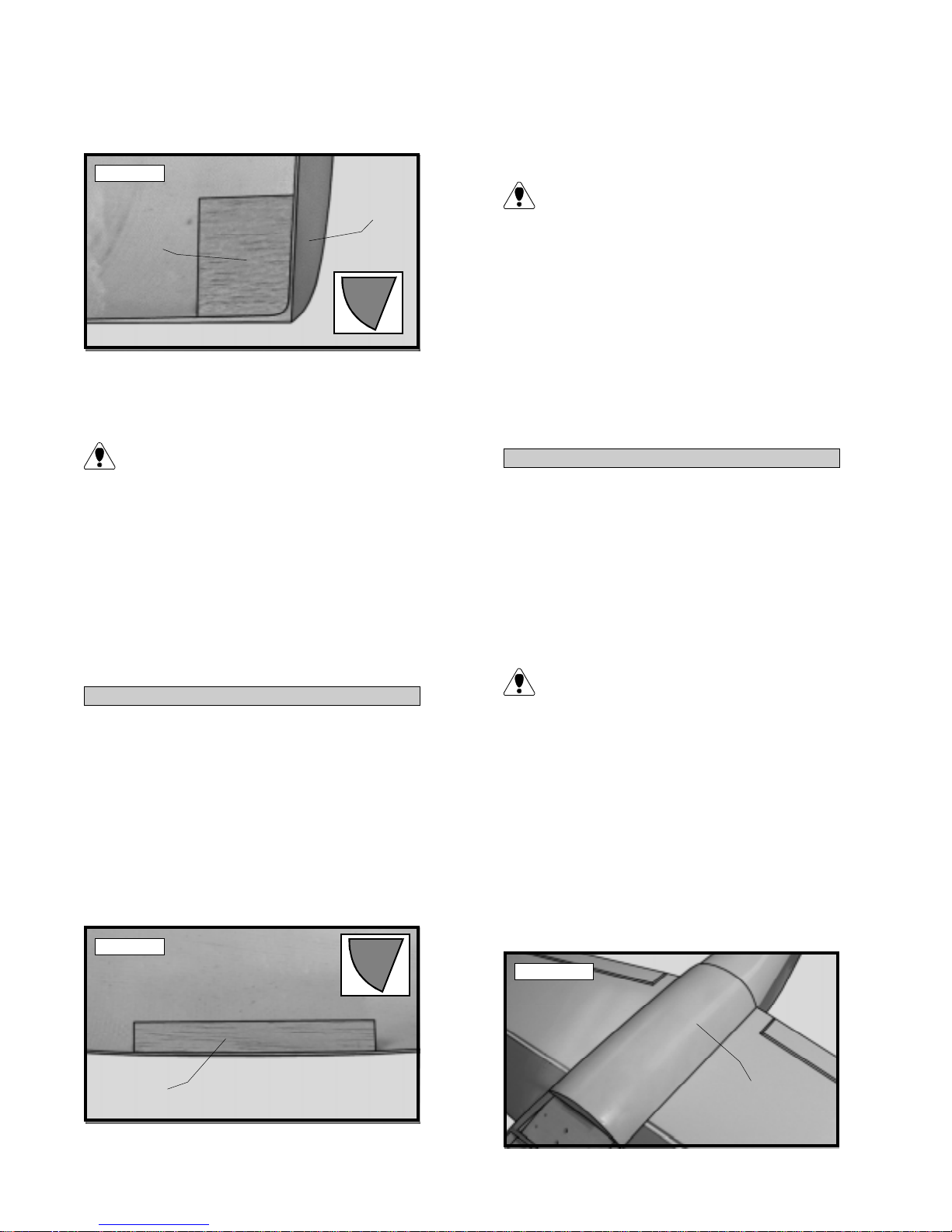
to match the contour of the belly pan. The top side
of each block should be flush with the bottom edges
of the belly pan. See photo # 8 below .
o 5) When satisfied with the fit of the triangle
stock, use 220 grit sandpaper and roughen the
surface of the belly pan where it will be glued.
Photo # 8
BELLY
PAN
MOUNTING
BLOCK
o 2) When satisfied with the fit of each block,
use 220 grit sandpaper and roughen the surface
of the belly pan where each block will be glued.
Roughening the surface of the fiberglass belly
pan will help strengthen the bond between
the epoxy and the fiberglass and prevent the
blocks from breaking off after they have been
glued in place.
o 3) Mix up a small amount of Kwik Bond 5
Minute Epoxy . Working with one mounting block
at a time, glue the block into the belly pan and
hold it in place with masking tape. When you
have glued in all four blocks, allow the assembly
to fully cure before proceeding.
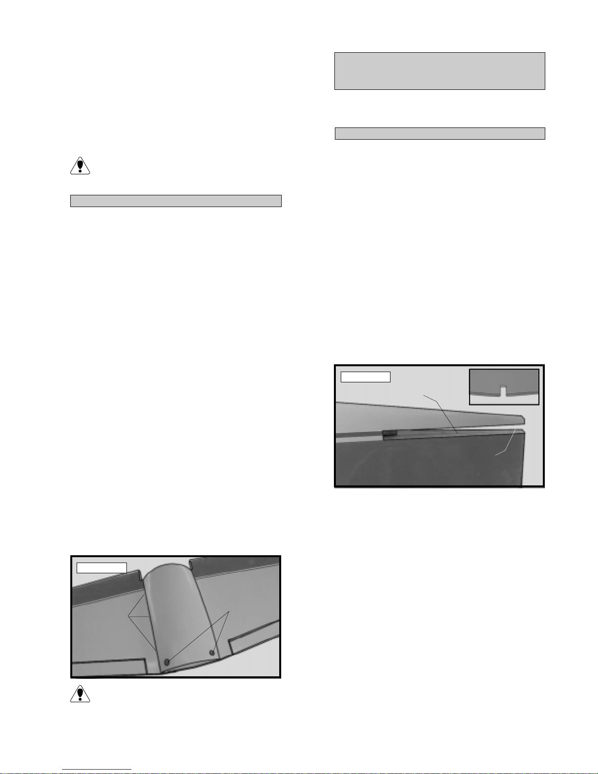
INST ALLING THE TRIANGLE SUPPORTS
o 4) Remove the masking tape from the four
mounting blocks. Trial fit the two balsa triangle
supports (D-33) to the inside edges of each side
of the belly pan. The triangle supports should
also be centered in the belly pan. Use 220 grit
sandpaper with a sanding block to shape the triangle stock to match the contour of the belly pan.
The top edge of the triangle stock should be flush
with the bottom edge of the belly pan. See photo
# 9 below .
Photo # 9
BELLY P AN
Roughening the surface of the fiberglass belly
pan will help strengthen the bond between
the epoxy and the fiberglass and prevent the triangle stock from breaking off after they has been
glued in place.
o 6) Mix up a small amount of Kwik Bond 5
Minute Epoxy . W orking with one piece of triangle stock at a time, glue the stock into the belly
pan and hold it in place with masking tape. After
you have glued both pieces in, allow the assembly to fully cure before proceeding.
ALIGNING THE BELL Y PAN
o 7) Remove the masking tape from the triangle stock. With the wing securely attached to
the fuselage, trial fit the belly pan to the bottom of
the wing. The sides of the belly pan, at both the
front and the rear, should be flush with the sides
of the fuselage. The curve at the rear of the belly
pan should also be flush with the curve of the fuselage bottom.
Y ou may find it necessary to press the sides
of the belly pan against the wing surface to
help in alignment. The edges of the belly pan may
also need adjustment. If so, carefully sand the
edges using 220 grit sandpaper until you are satisfied with the fit.
o 8) Using a modeling knife, remove the portion of the rear mounting blocks that interfere with
the wing bolt doubler and wing mounting screws.
o 9) When satisfied with the fit, hold the belly
pan in place using pieces of masking tape. See
photo # 10 below.
Photo # 10
TRIANGLE
STOCK
BELLY PAN
8
Page 9
o 10) With the belly pan held firmly in place and
aligned properly , use a pen and outline the outside
edges of the belly pan onto the wing surface.
HORIZONTAL STABILIZER
MOUNTING
o 11) Remove the belly pan. Using the lines
as a guide use a modeling knife and remove the
covering from between them.
Removing the covering will allow a stronger
bond between the belly pan and the wing
when the belly pan is glued in place.
INST ALLING THE BELLY P AN
o 12) Mix up a generous amount of Kwik
Bond 30 Minute Epoxy . Apply a thin layer of
epoxy to the bottom portion of each of the four
mounting blocks and both triangle supports. Carefully set the belly pan back in place on the wing
and align it as you did previously . Hold the belly
pan firmly in place using pieces of masking tape.
o 13) Remove any excess epoxy using a paper towel and rubbing alcohol. Allow the epoxy
to fully cure before proceeding.
o 14) Using a pen, mark the locations on the
belly pan of the two wing hold down screws. The
holes will be located 1” in from the fuselage sides
and 1-1/8” forward of the rear edge of the belly
pan at it's centerline.
PARTS REQUIRED
o {1} Horizontal Stabilizer w/Elevator Halves and Hinges
ALIGN THE HORIZONT AL STABILIZER
o 1) Remove the two elevator halves from the
horizontal stabilizer and set them aside for now .
o 2) Using a ruler and a pen, locate and mark
the centerline of the horizontal stabilizer at the
trailing edge and place a mark. Use a triangle
and extend this mark, from back to front, across
the top and bottom of the stabilizer.
o 3) Using a modeling knife, carefully remove
the covering from over the stabilizer slot precut in
the rear of the fuselage. There is also a precovered
balsa block tack glued in the rear of the slot.
Carefully remove this block using a modeling knife
and set it aside for later use. Also remove the
covering from over the precut notch in the leading edge of the stabilizer . See photo # 12 below.
Photo # 12
REMOVE COVERING
o 15) Using a 3/8” drill bit, drill two holes
through the belly pan to access the wing bolts.
o 16) Remove the wing from the fuselage. Apply a thin bead of Kwik Bond Thin C/A between
the edge of the belly pan and the surface of the
wing. The C/A will wick into the seam and secure
the belly pan in place. See photo # 11 below .
Photo # 1 1
DRILL ACCESS
HOLES
APPLY
THIN C/A
(both sides)
Do not use too much Thin C/A. The C/A is
very thin, and if too much is used, it may run
out onto the covering.
LOCATION
OF BLOCK
o 4) Slide the stabilizer into the slot. The stabilizer should be pushed firmly up against the front
of the slot. Make sure the notch in the leading
edge of the stabilizer fully engages the preinstalled
block at the front of the slot.
o 5) Attach the wing to the fuselage. Align the
centerline mark on top of the stabilizer with the
centerline of the fuselage at the rear. When that is
aligned hold the stabilizer in that position using a Tpin and align the horizontal stabilizer with the wing.
When viewed from the rear, the horizontal stabilizer should be level with the wing. If it is not level,
use sandpaper and sand down the high side of the
stabilizer mounting platform until the proper alignment is achieved. The tips of the stabilizer should
also be equal distance from the tips of the wing.
See figures # 2 and # 3 at top right.
9
Page 10
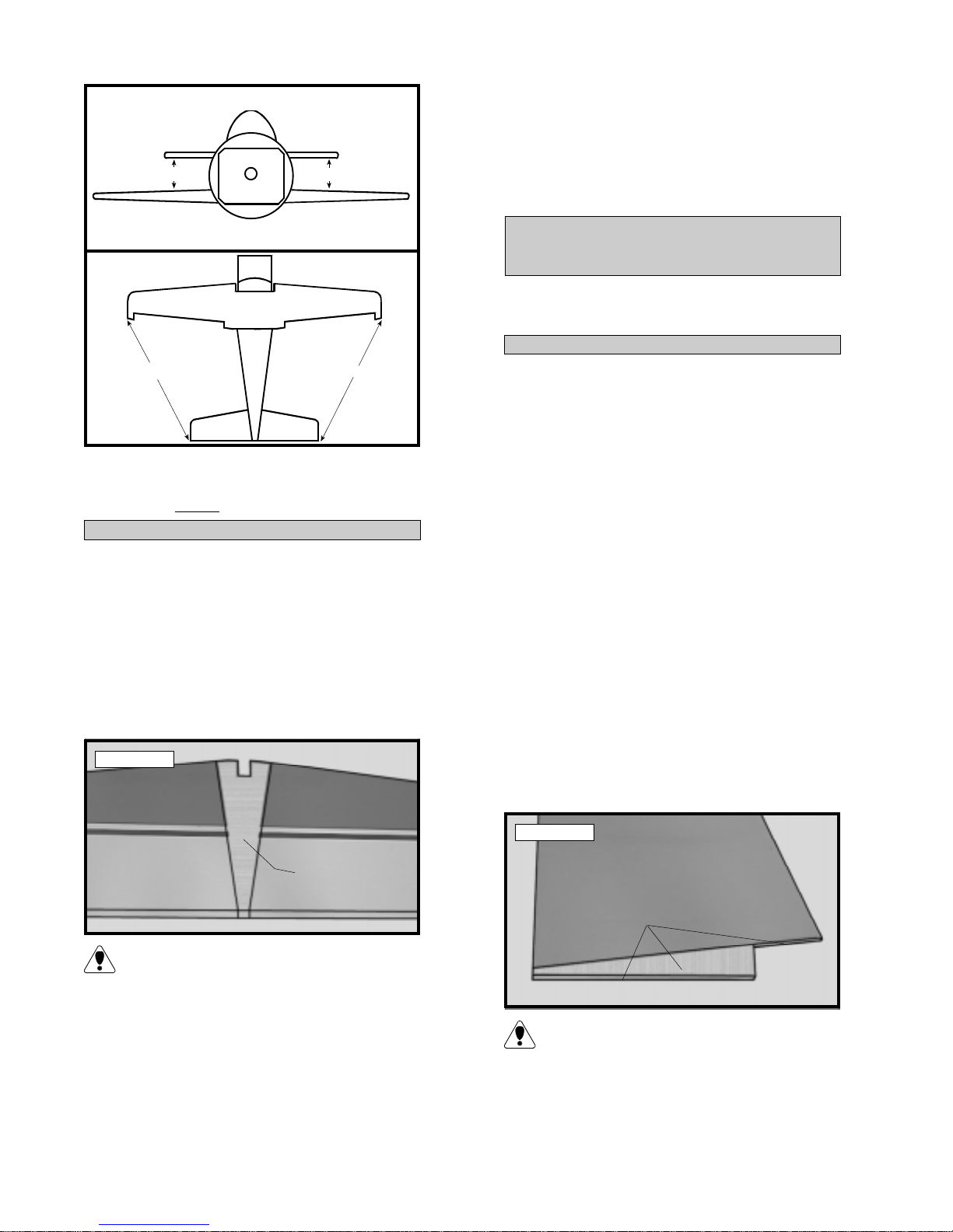
Figure # 2
Figure # 3
the fuselage. Slide the stabilizer in place and realign. Double check all of your measurements
once more before the epoxy cures. Hold the stabilizer in place with T-pins or masking tape and
A
A1
remove any excess epoxy using paper towels and
rubbing alcohol.
VERTICAL STABILIZER
MOUNTING
PARTS REQUIRED
o {1} V ertical Stabilizer w/Rudder and Hinges
ALIGN THE VERTICAL ST ABILIZER
A
A1
o 6) When you are satisfied with the alignment,
hold the stabilizer in place with T- pins or masking tape, but do not glue at this time.
MOUNTING THE HORIZONT AL STABILIZER
o 7) With the stabilizer held firmly in place, use
a pen and draw lines where it and the fuselage
sides meet. Do this on both the right and left sides
and top and bottom of the stabilizer.
o 8) Remove the stabilizer. Using the lines you
just drew as a guide, carefully remove the covering
from between them using a modeling knife. See
photo # 13 below.
Photo # 13
o 1) Using a modeling knife, carefully remove
the covering from over the stabilizer slot precut in
the top rear of the fuselage.
o 2) Remove the rudder from the stabilizer.
Slide the stabilizer into the slot in the top of the
fuselage. The rear edge of the stabilizer should
be even with the rear edge of the fuselage and it
should be firmly pushed down completely into the
slot.
o 3) Using a pen, draw a line on each side of
the vertical stabilizer where it meets the top of the
fuselage.
o 4) Remove the stabilizer. Using a modeling
knife, remove the covering from below the lines
you drew . Also remove the covering from the
bottom edge of the stabilizer. See photo # 14
below.
REMOVE
COVERING
(Top & Bottom)
When cutting through the covering to re-
move it, cut with only enough pressure to
only cut through the covering itself. Cutting into
the balsa structure may weaken it.
o 9) When you are sure that everything is
aligned correctly , mix up a generous amount of
Kwik Bond 30 Minute Epoxy . Apply a thin layer
to the top and bottom of the stabilizer mounting
area and to the stabilizer mounting platform on
Photo # 14
REMOVE
COVERING
When cutting through the covering to re-
move it, cut with only enough pressure to
only cut through the covering itself. Cutting into
the balsa structure may weaken it.
10
Page 11
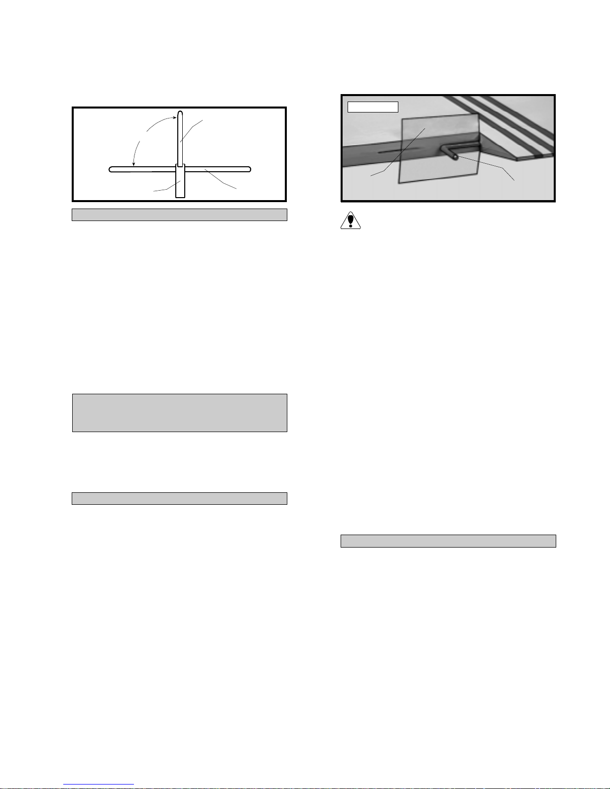
o 5) Slide the vertical stabilizer back in place.
Using a triangle, check to ensure that the vertical
stabilizer is aligned 90º to the horizontal stabilizer .
See figure # 4 below .
Figure # 4
90º
VERTICAL
STABILIZER
o 3) Slide a small piece of waxed paper between the aileron torque rod and the trailing edge
of the wing. See photo # 15 below.
Photo # 15
FUSELAGE
MOUNTING THE VERTICAL ST ABILIZER
HORIZONTAL
STABILIZER
o 6) When you are sure that everything is
aligned correctly , mix up a generous amount of
Kwik Bond 30 Minute Epoxy . Apply a thin layer
to the mounting slot in the top of the fuselage and
to the sides and bottom of the vertical stabilizer
mounting area. Set the stabilizer in place and realign. Double check all of your measurements
once more before the epoxy cures. Hold the stabilizer in place with T-pins or masking tape and
remove any excess epoxy using paper towels and
rubbing alcohol. Allow the epoxy to fully cure
before proceeding.
CONTROL SURFACE
INSTALLATION
PARTS REQUIRED
o {2} Ailerons w/Hinges
o { 2 } Elevator Halves w/Hinges
o { 1 } Rudder w/Hinges
WAXED
PAPER
TORQUE ROD
The waxed paper will prevent epoxy from
gluing the torque rod to the trailing edge of
the wing.
o 4) Mix up a small amount of Kwik Bond 30
Minute Epoxy . Apply a thin layer of epoxy to the
aileron torque rod. Also use a toothpick and pack
epoxy into the predrilled hole in the aileron.
o 5) Slide the aileron and it's hinges into their
precut hinge slots in the trailing edge of the wing,
making sure the torque rod is firmly seated in the
precut hole in the leading edge of the aileron. With
the aileron tight against the wing, rotate the aileron down about 45º. Apply six drops of Kwik
Bond Thin C/A to the exposed area of each hinge.
Allow the glue to cure for about ten minutes.
Once cured, the aileron may be stiff and difficult
to move. This is normal. Gently move the aileron
up and down about five to ten times to free it up.
HINGE THE AILERONS
o 1) The C/A hinges have already been glued
into the two ailerons. W orking with one aileron
at a time, slide the aileron and it's hinges into their
precut hinge slots in the trailing edge of the wing,
making sure the torque rod is firmly seated in the
precut hole in the leading edge of the aileron. Slide
the aileron in until it is tight against the trailing
edge of the wing. The maximum hinge gap should
be no more than 1/32”.
o 2) When satisfied with the fit, remove the
aileron. Using a modeling knife, carefully remove
any excess covering material that may have overlapped onto the hinges. Do not cut through the
hinges!
o 6) Repeat steps # 1 - # 5 for the second
aileron.
HINGE THE ELEV A TOR HALVES
o 7) The C/A hinges have already been glued
into the two elevator halves. W orking with one half
at a time, slide the elevator and it's hinges into their
precut hinge slots in the trailing edge of the horizontal stabilizer. Slide the elevator in until it is tight
against the trailing edge of the stabilizer . The maximum hinge gap should be no more than 1/32”.
o 8) When satisfied with the fit, remove the
elevator. Using a modeling knife, carefully remove any excess covering material that may have
overlapped onto the hinges. Do not cut through
the hinges!
11
Page 12
o 9) With the elevator tight against the stabilizer, rotate the elevator down about 45º. Apply
six drops of Kwik Bond Thin C/A to the exposed
area of each hinge. Allow the glue to cure for
about ten minutes. Once cured, the elevator may
be stiff and difficult to move. This is normal.
Gently move the elevator up and down about five
to ten times to free it up.
o 10) Repeat steps # 7 - # 9 for the second
elevator half.
HINGE THE RUDDER
o 11) Using a modeling knife, remove the covering from over the lower hinge slot precut in the
back edge of the fuselage. Use the rudder to
help locate the slot.
o 12) The C/A hinges have already been glued
into the rudder. Slide the rudder and it's hinges
into their precut hinge slots in the trailing edge of
the vertical stabilizer and lower section of the fuselage. Slide the rudder in until it is tight against
the trailing edge of the stabilizer . The maximum
hinge gap should be no more than 1/32”.
o 13) When satisfied with the fit, remove the
rudder . Using a modeling knife, carefully remove
any excess covering material that may have overlapped onto the hinges. Do not cut through the
hinges!
TAIL WHEEL INSTALLATION
PARTS REQUIRED
o {1} Nylon Tiller Arm
o {1 } Nylon Tail Wheel Bracket
o {1 } 25mm Diameter Wheel
o {1 } Tail Wheel Wire
o {2 } Wheel Collars w/3mm x 6mm Machine Screws
o {3 } 3mm x 12mm Wood Screws
o {1} 2.5mm x 10mm Wood Screw
TAIL WHEEL BRACKET ASSEMBL Y
o 1) Insert one wheel collar into the top of the
nylon tiller arm, making sure the threaded hole in
the wheel collar lines up with the hole in the side
of the tiller arm.
o 2) Install one 3mm x 6mm machine screw
through the tiller arm and into the wheel collar,
but do not tighten the screw at this time.
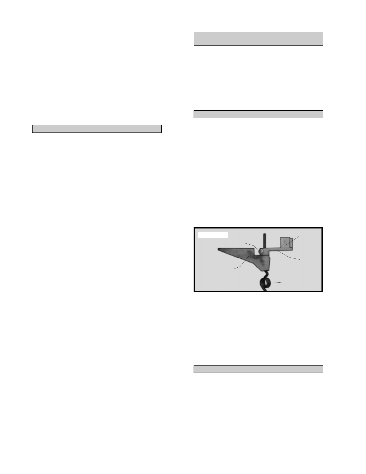
o 3) Slide the tail wheel wire up through the
bottom of the nylon bracket. Slide the tiller arm
over the tail wheel wire, making sure the mounting clasp is facing up. See photo # 16 below.
Photo # 16
NYLON
BRACKET
SET
SCREW
MOUNTING
CLASP
TILLER
ARM
TAIL WHEEL
WIRE
o 14) Slide the rudder and it's hinges into their
precut hinge slots in the trailing edge of the vertical stabilizer and lower section of the fuselage.
With the rudder tight against the stabilizer , rotate
the rudder to one side about 45º. Apply six drops
of Kwik Bond Thin C/A to the exposed area of
each hinge. Allow the glue to cure for about ten
minutes. Once cured, the rudder may be stiff and
difficult to move. This is normal. Gently move
the rudder back and forth about five to ten times
to free it up.
o 15) After the C/A has completely cured on
all of the control surfaces, gently grasp each control surface and pull lightly . If any hinges appear
to be loose, apply a few more drops of Kwik
Bond Thin C/A to that particular hinge or hinges
to secure them in place.
o 4) Adjust the height of the tail wheel wire.
The top of the wire should protrude 5/8” above
the top of the tiller arm. Adjust the tail wheel wire
so it is also parallel with the tiller arm. When satisfied with the alignment, tighten the 3mm x 6mm
machine screw to secure the wire in place. If you
wish you can either leave the excess tail wheel wire
as-is or cut it off flush with the tiller arm.
INST ALLING THE TAIL WHEEL
o 5) Install the 25mm diameter tail wheel onto
the tail wheel wire. Secure the tail wheel in place
using one wheel collar and one 3mm x 6mm machine screw . Slide the wheel collar on enough so
it is up against the tail wheel, but not so tight that
the tail wheel won't turn. The tail wheel should
rotate without binding.
12
Page 13
MOUNTING THE TAIL WHEEL BRACKET
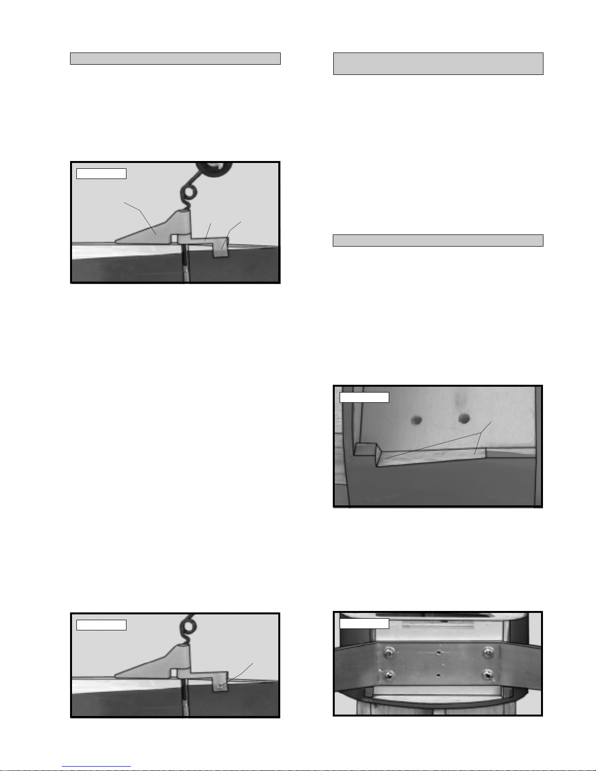
o 6) Trial fit the tail wheel bracket assembly
to the fuselage and rudder. The nylon clasp
molded into the tiller arm should slide over the
bottom edge of the rudder. The tail wheel wire
should be parallel to the rudder hinge line and the
nylon bracket should be aligned with the centerline of the fuselage. See photo # 17 below .
Photo # 17
NYLON
BRACKET
TILLER
ARM
NYLON
CLASP
o 7) While holding the tail wheel mounting
bracket aligned with the centerline of the fuselage, use a pen and mark the three mounting locations onto the fuselage.
o 8) Move the mounting bracket to the side.
Using a 1/16” drill bit, drill three pilot holes through
the bottom of the fuselage at the marks you just
made.
o 9) Secure the mounting bracket in place using three 3mm x 12mm wood screws.
MAIN LANDING GEAR
PARTS REQUIRED
o {1} Aluminum Main Gear Strut
o {4 } 4mm x 12mm Machine Screws
o {8 } 4mm Flat Washers
o {4 } 4mm Blind Nuts
o {2} 4mm x 30mm Axle Screws
o {4 } 4mm Nylon Insert Nuts
o { 2 } Nylon Axle Spacers
o { 2} 76mm Diameter Wheels
o {2 } 3mm x 15mm Machine Screws
o {2 } 3mm Flat Washers
o { 1} Gear Cover Mounting Block (D-31)
o { 1} Molded Fiberglass Gear Cover
INST ALLING THE GEAR BRACKET
o 1) Place the gear bracket onto the mounting
platform on the bottom of the fuselage. Align the
predrilled holes in the gear bracket with the predrilled holes in the mounting platform.
o 2) Using a modeling knife and the landing
gear as a guide, carefully trim the fuselage sides,
small amounts at a time, until the gear bracket
sits flush onto the mounting platform. See photo
# 19 below.
Photo # 19
TRIM SIDE
(Left & Right)
o 10) Hold the rudder in neutral using a couple
of pieces of masking tape. Using a 1/16” drill bit,
drill a hole through the rudder for the nylon clasp
mounting screw . Use the predrilled holes in the
clasp as a guide.
o 11) Secure the tiller arm to the rudder using
one 2.5mm x 10mm wood screw threaded
through one side of the clasp, through the rudder,
and into the opposite side of the clasp. Tighten
the screw , but do not overtighten. Y ou don't want
to crush the wood or break the clasp. See photo
# 18 below .
Photo # 18
WOOD
SCREW
o 3) When satisfied with the fit install the gear
bracket using the four 4mm blind nuts, four 4mm
machine screws and four 4mm flat washers. Install the blind nuts up from the bottom, through
the fuel tank compartment. Draw them up into
place by tightening the machine screws completely .
See photo # 20 below.
Photo # 20
13
Page 14

INST ALLING THE GEAR COVER
o 4) Bolt the gear cover block (D-31) to the
main gear bracket using two 3mm x 15mm machine screws and two 3mm flat washers. The
block should be orientated with the countersunk
holes facing up and the angle (taller side towards
the front) facing the rear of the fuselage. See
photo # 21 below.
Photo # 21
GEAR COVER
BLOCK
o 5) Using a ruler, measure the distance from
the rear edge of the plywood cowl ring to the
center of each predrilled hole in the gear cover
block. The measurements should be approximately 9/16” to the forward hole and 1-1/4” to
the rear hole. Make a notation of these measurements on scrap paper for later reference.
o 6) Trial fit the fiberglass gear cover over the
gear bracket. Using a Dremel T ool with a cutting
disc, remove the portion of the gear cover that interferes with the landing gear bracket. See photo
# 22 below.
Photo # 22
GEAR
COVER
o 8) Mix up a small amount of Kwik Bond 5
Minute Epoxy . Apply a generous layer of epoxy
to the top of the mounting block, being careful
not to get any glue into the two holes.
o 9) Set the gear cover in position and realign.
Hold the gear cover in place using a couple of
pieces of masking tape. Allow the epoxy to completely cure. Remove the wing.
o 10) Using the measurements found in step
# 5, locate the position of the predrilled holes in
the mounting block beneath the gear cover.
o 11) Using a 1/4” drill bit, drill two holes
through the gear cover at the two marks made.
See photo # 23 below.
Photo # 23
DRILL
HOLES
Opening the access holes through the gear
cover will allow removal of the gear cover
assembly so the landing gear bracket can be serviced if necessary .
INST ALLING THE MAIN GEAR WHEELS
o 12) W orking with only one wheel assembly
at this time, slide one 4mm flat washer onto one
4mm x 30mm axle screw . Slide one 76mm diameter wheel onto the 4mm x 30mm axle screw .
The wheel should go on with the recessed side of
the hub first.
REMOVE FOR
GEAR BRACKET
CLEARANCE
o 7) Install the wing onto the fuselage and set
the gear cover in place. The front and rear edges
of the gear cover should align with the fuselage
and the belly pan. When satisfied with the fit, use
220 grit sand paper and roughen the inside surface of the gear cover, where it will be glued to
the mounting block.
Y ou may need to trim the top of the mounting block to allow the gear cover to fit flush
with the bottom of the fuselage.
o 13) Slide one 4mm flat washer onto the axle
screw and up against the wheel. Slide one 4mm
nylon spacer onto the axle screw . Install one 4mm
nylon insert nut onto the axle screw and tighten it
against the nylon spacer. Adjust the nut so the
wheel spins free, but it not too loose. See photo
# 24 below .
Photo # 24
NUT
SPACER
AXLE
WASHER
14
Page 15
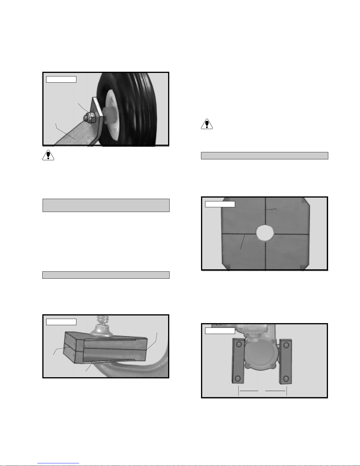
o 14) Slide the wheel assembly through the
predrilled hole in the landing gear bracket. Thread
one 4mm nylon insert nut onto the machine screw
and tighten it completely to hold the axle assembly in place. See photo # 25 below.
o 3) When satisfied with the alignment of the
engine, remove the beams from the clamp and
drill 1/8” holes through the mounting beams at
the four engine mounting hole locations.
Photo # 25
NUT
GEAR
BRACKET
When tightening the second nylon insert nut
be careful not to allow the first nylon insert
nut to tighten against the wheel.
o 15) Repeat steps # 12 - # 14 for the second
wheel assembly .
ENGINE MOUNTING
PARTS REQUIRED
o {2} Nylon Motor Mount Beams
o {4 } 3mm x 25mm Machine Screws
o {4} 3mm x 20mm Machine Screws
o {4 } 3mm Nylon Insert Nuts
o { 4} 3mm Blind Nuts
o {12} 3mm Flat W ashers
o 4) Mount the engine to the mounting beams
using the four 3mm x 25mm machine screws, eight
3mm flat washers and four 3mm lock nuts. Tighten
the screws and nuts completely .
If using an engine equipped with a remote
needle valve we recommend mounting the
needle valve to the engine prior to installing the
engine on the motor mount beams.
ALIGNING THE MOTOR MOUNT
o 5) The engine is mounted sideways on the
firewall. Using a ruler and a pen, measure and
draw a vertical centerline and a horizontal centerline on the firewall. See photo # 27 below.
Photo # 27
HORIZONTAL
CENTERLINE
VERTICAL
CENTERLINE
MOUNTING ENGINE TO MOTOR MOUNT
o 1) Using a clamp or a vise, align the two motor
mount beams and clamp them together. The beam
halves are universal and the webbing should face
the outside edges. See photo # 26 below.
Photo # 26
MAKE
EVEN
WEBBING
MAKE
EVEN
o 2) Mark the locations of the four engine
mounting holes on the beams using a pencil. For
the engine to align properly with the cowling, it is
important that the front edge of the engine's drive
washer be 4-1/8” forward from the rear edge of
the mounting beams.
15
o 6) With your engine still installed on the motor mount beams, use a ruler and measure the width
between the predrilled mounting holes in the motor
mount. This distance will vary depending on the
brand and size of the engine you have chosen. See
photo # 28 below.
Photo # 28
D = Width
between
predrilled
mounting
holes
D
o 7) Divide the measurement found in step # 6
in half. Measure this resulting distance and draw
one horizontal line above and below the horizontal
centerline.
Page 16
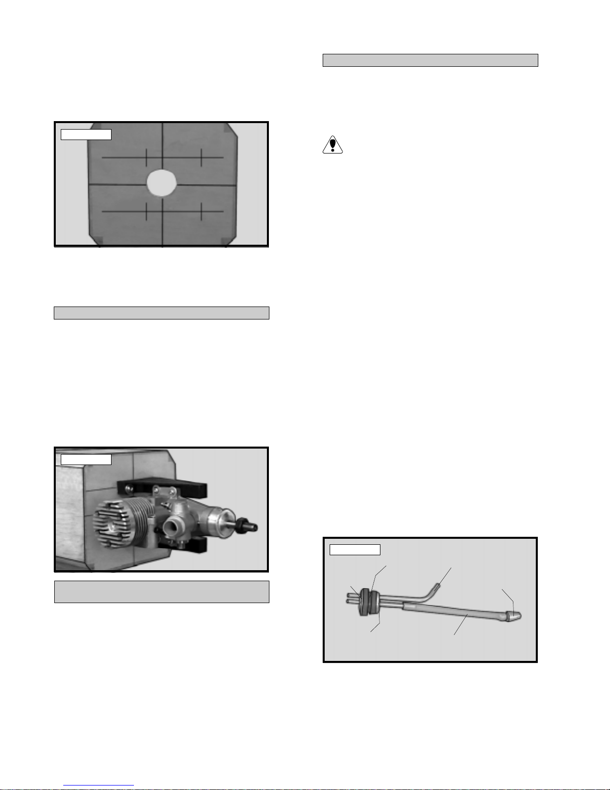
o 8) On the two horizontal lines you just
drew, measure and place marks 1/2” to the
left and 13/16” to the right of the vertical centerline (looking at the firewall). See photo #
29 below .
FUEL T ANK ASSEMBLY
o 1) The fuel tank assembly incudes 3 different length aluminum tubes. Discard the shortest
of the three. It will not be used.
Photo # 29
o 9) Hold the motor mount assembly up to the
firewall and double check that the four intersecting lines line up with the four predrilled holes in
the motor mount.
MOUNTING THE ENGINE TO FIREW ALL
o 10) Using a 1/8” drill bit, drill the four mounting holes through the firewall for the motor mount.
o 11) Mount the motor mount assembly to the
firewall using the four 3mm x 20mm machine
screws, four 3mm flat washers and four 3mm blind
nuts. Tighten the screws completely until the blind
nuts have been completely seated in the back of
the firewall. See photo # 30 below .
Photo # 30
The 50mm length tube is used for the fuel
line pickup and the 80mm tube is used for
the vent/pressure line.
o 2) Using 220 grit sandpaper carefully
smooth each end of the two tubes. This will prevent the fuel line from being cut.
o 3) Push the two aluminum tubes through the
rubber stopper until 1/2” protrudes from the front
of the stopper . Slide the 20mm diameter front
squash plate over the tubes at the front of the
stopper and slide the 18mm diameter rear squash
plate over the tubes at the rear of the stopper.
Insert the 3mm x 20mm machine screw into the
center hole in the front squash plate, then screw it
through the stopper and into the rear squash plate.
Do not completely tighten the screw at this time.
o 4) Carefully bend the longer of the two tubes
up at a 45º angle. This tube is the vent tube.
When the stopper assembly is installed in the tank,
the top of the vent tube should rest just inside the
bubble in the top of the tank.
FUEL TANK
PARTS REQUIRED
o {1} Molded Fuel T ank
o {1} Rubber Stopper
o {1 } 20mm Diameter Front Squash Plate
o {1 } 18mm Diameter Rear Squash Plate
o {1 } 3mm x 20mm Machine Screw
o {1 } Weighted Metal Pick-Up
o { 3 } Aluminum Tubes
o { 1} 90mm Silicon Fuel Tube
o 5) Slide the silicon fuel tubing, with the
weighted pickup attached to one end, onto the
fuel pickup tube. See photo # 31 below .
Photo # 31
FRONT
SQUASH
PLATE
REAR
SQUASH
PLATE
RUBBER
STOPPER
FUEL
PICKUP
TUBE
VENT TUBE
WEIGHTED
PICKUP
FUEL TUBING
o 6) Test fit the stopper assembly into the
tank. It may be necessary to remove some of
the flashing around the tank opening using a
modeling knife. If flashing is present, make sure
none falls into the tank.
16
Page 17

o 7) With the stopper assembly in place the
weighted pickup should rest about 3/8” away from
the rear of the tank and move freely inside the
tank. The vent tube should be inside the bubble
in the tank, but not rub against the tank. Adjust
the tubes accordingly .
Photo # 32
o 8) When satisfied with the alignment of the
stopper assembly tighten the 3mm x 20mm machine screw until the rubber stopper expands and
seals the tank opening. Do not overtighten the
assembly as this could cause the tank to split.
FUEL T ANK INSTALLA TION
o 9) Slide the fuel tank into the fuel tank compartment in the front of the airplane. The bubble
in the tank should face the top of the fuselage and
the stopper assembly should engage the predrilled
hole in the firewall. The rear edge of the tank
should be even with the forward bulkhead. This
will prevent the wing from interfering with the tank
when it is mounted.
o 10) Secure the fuel tank in place using several pieces of foam rubber . Seal any gaps between the stopper assembly and the firewall using
silicon sealer. Be careful not to get any sealer
inside the aluminum tubing.
THROTTLE LINKAGE
PUSHROD
WIRE
Z-BEND
SERVO INSTALLATION
PARTS REQUIRED
o {2 } Aileron Servo Mounting Plates (W-37)
o { 1 } Fuselage Servo Tray (D-10)
INSTALLING THE FUSELAGE SER VOS
o 1) Install the rubber grommets and brass collets provided with your radio system onto four servos. T est fit two of the servos into the two precut
servo holes in the fuselage servo tray (D-10). These
will be the elevator and rudder servos.
Because the size of servos differ , you may
need to adjust the size of the precut openings. Y ou may also need to use a modeling knife
and cut a groove to allow room for the servo wires.
PARTS REQUIRED
o {1} 2mm x 300mm Pushrod Wire w/Z-Bend
INSTALLING THE THROTTLE LINKAGE
o 1) Locate and drill a 3/32” hole through the
firewall for the throttle pushrod wire to pass
through (you may need to temporarily remove the
engine). The hole should be level with the throttle
arm, but may need to be moved slightly to clear
the fuel tank depending on the engine used.
Be careful not to drill through the fuel tank
that has already been installed.
o 2) Slide the plain end of the pushrod wire
through the hole and into the fuselage. Remove
the throttle arm from the carburetor and attach
the Z-bend to the outer hole in the arm.
o 3) Reattach the throttle arm to the carburetor and use a pair of pliers to make any necessary
bends in the wire so it does not bind when the
carburetor is moved from the idle to the full throttle
position. See photo # 32 at top right.
o 2) Install the elevator and rudder servos using the wood screws provided with your radio
system. Drill 1/16” pilot holes through the tray
before installing the screws. This will help prevent the wood from splitting. Install the servos
with the output shafts in the orientation shown.
See photo # 33 below .
Photo # 33
FRONT
SERVO TRAY
17
Page 18
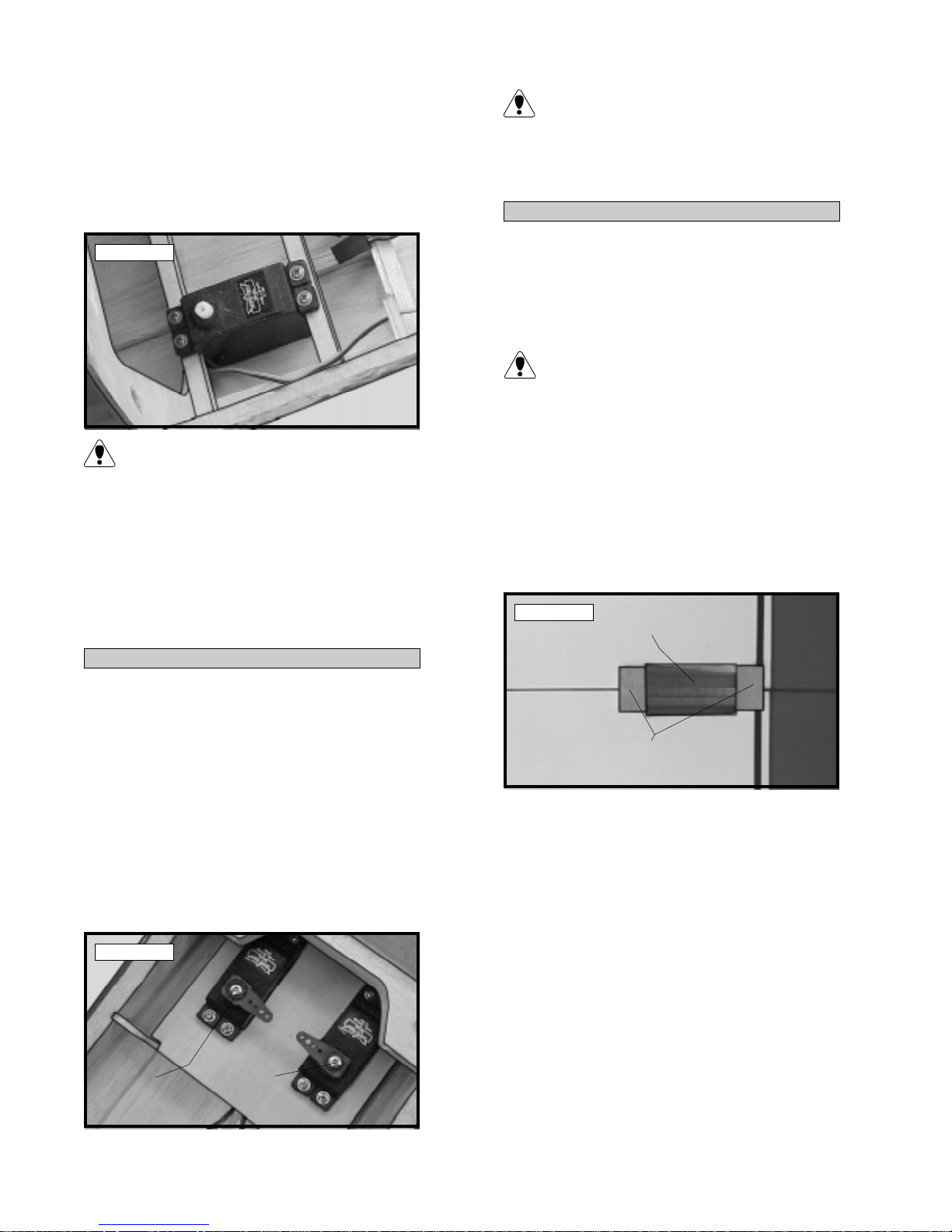
o 3) Test fit the throttle servo between the two
preinstalled servo rails just behind the forward
bulkhead. The servo should be mounted on the
right side of the fuselage, about 1” in from the
inside edge of the fuselage side, with the output
shaft towards the front of the airplane. See photo
# 34 below .
Photo # 34
Because the size of servos differ , you may
need to adjust the width of the rails. If necessary , use a modeling knife to trim the inside
edges of the rails to fit the servo.
o 4) Install the throttle servo using the wood
screws provided with your radio system. Drill
1/16” pilot holes through the rails before installing the screws. This will help prevent the wood
from splitting.
INST ALLING THE SERVO TRA Y
T o facilitate servo removal in the future, we
recommend drilling a hole through the wing
mounting bulkhead over each rear servo mounting screw . Drill the hole no larger than necessary
for a thin shanked screwdriver to fit through.
INST ALLING THE AILERON SERVO
o 7) Test fit the servo into the precut servo
hole in the top side of the wing. The output shaft
should be pointing towards the leading edge of
the wing.
Because the size of servos differ , you may
need to adjust the size of the precut opening. Y ou may also need to use a modeling knife
and cut a groove to allow room for the servo wire
to exit the hole.
o 8) Remove the servo and position the two
servo mounting plates (W-37) onto the wing. The
plates should be centered from side to side and
the inside edges should be even with the servo
opening. See photo # 36 below.
Photo # 36
SERVO
OPENING
o 5) Trial fit the servo tray , with the servos installed, into the fuselage. The front and rear of
the tray has precut notches that correspond with
notches in the rear bulkhead and the center bulkhead. The servo output shafts should face the
front of the airplane.
o 6) When satisfied with the fit, remove the
tray and mix up a generous amount of Kwik Bond
5 Minute Epoxy . Glue the tray in place using the
epoxy . Allow the epoxy to cure fully before proceeding. See photo # 35 below.
Photo # 35
RUDDER
SERVO
ELEVA TOR
SERVO
MOUNTING
PLATES
o 9) Hold the two plates in position and trace
around them using a pen. Remove the plates and
using a modeling knife, remove the covering from
just inside the lines.
o 10) Mix a small amount of Kwik Bond 5
Minute Epoxy and glue the plates in place. Allow the epoxy to cure completely .
o 11) Install the servo using the wood screws
provided with your radio system. Drill 1/16” pilot holes through the plates before installing the
screws. This will help prevent the wood from
splitting.
18
Page 19
THROTTLE CONNECTOR
PARTS REQUIRED
o {1} Adjustable Servo Connector Assembly
INSTALLING THE THROTTLE CONNECTOR
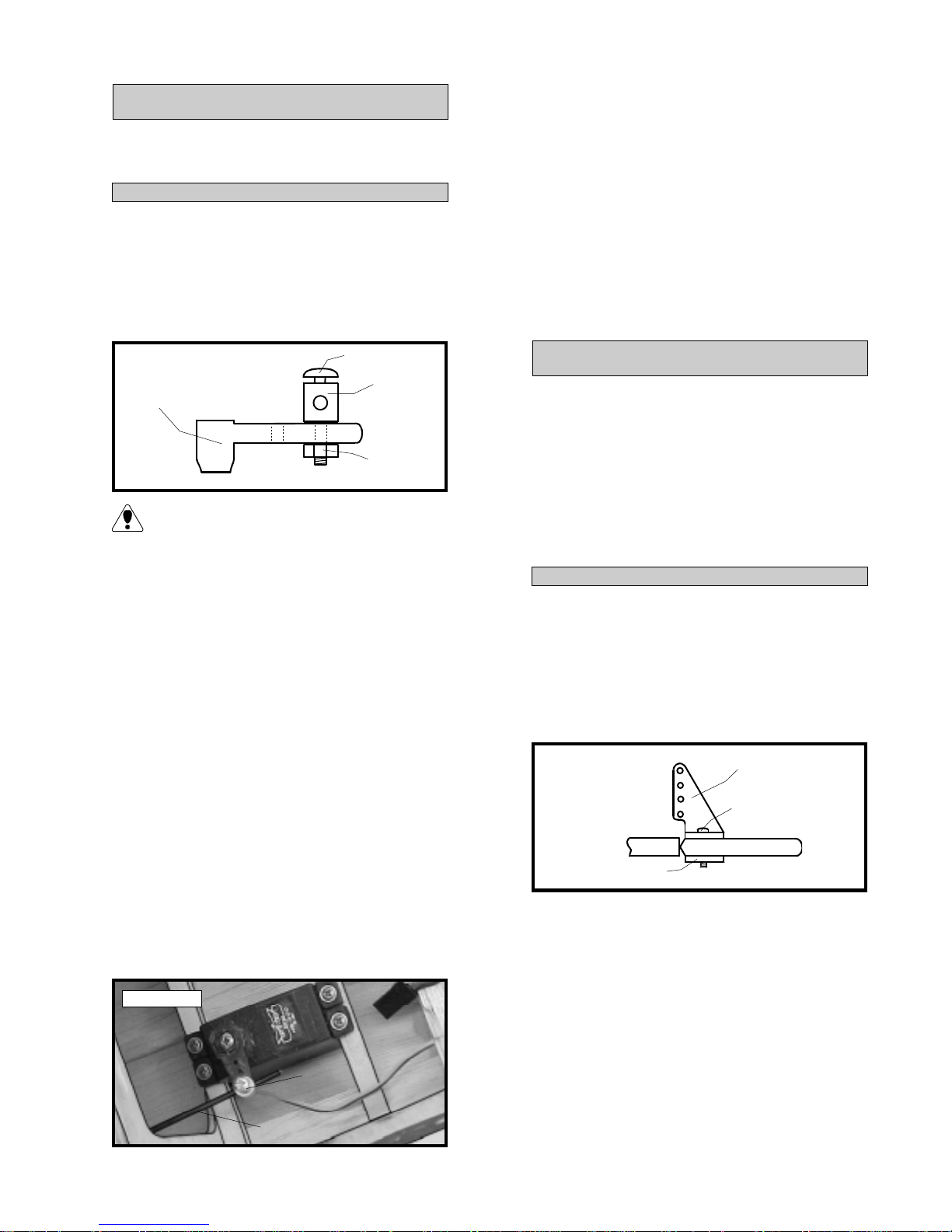
o 1) Install one adjustable servo connector
through the second hole out from the center of one
servo arm. Y ou may have to enlarge the hole in the
servo arm to accommodate the servo connector.
Remove the excess material from the servo arm
using wire cutters. See figure # 5 below.
o 5) T est the movement of the throttle pushrod. Full forward stick and full forward trim should
result in the carburetor barrel opening completely .
Full back stick and full forward trim should result
in the approximate idle setting. Full back stick
and full down trim should result in the carburetor
barrel closing fully .
o 6) When satisfied that the pushrod linkage
is adjusted correctly and no binding is present,
install the servo arm set screw and remove any
excess pushrod wire using wire cutters.
Figure # 5
SERVO ARM
SET SCREW
SERVO
CONNECTOR
NUT
After installing the adjustable servo connec-
tor apply a small drop of Kwik Bond Thin
C/A to the nut. This will prevent the connector
from loosening during flight.
o 2) Turn on the radio system. Check to ensure that the throttle servo output shaft is moving
in the correct direction.
o 3) Slide the adjustable servo connector/
throttle arm assembly over the end of the throttle
pushrod wire. Position the throttle stick and the
throttle trim at their lowest positions.
o 4) Manually push the carburetor barrel fully
closed. Angle the servo arm back about 30º from
center and attach it to the servo. The arm should
face the left side of the airplane (looking from the
rear). With the carburetor barrel fully closed,
tighten the set screw in the adjustable servo connector. You will need to make a bend in the pushrod wire to allow it to align with the servo arm.
See photo # 37 below.
RUDDER PUSHROD
PARTS REQUIRED
o {1 } Wood Dowel (D-34)
o {1 } 2mm x 90mm Wire w/L-Bends Both Ends
o {1 } 2mm x 210mm Wire Threaded One End
o {1 } Nylon Clevis w/2mm I.D. Hole
o {1} Nylon Snap Keeper
o { 1 } Nylon Control Horn (large)
o { 1 } Nylon Control Horn Backplate
o {2 } 2mm x 15mm Machine Screws
INSTALLING THE RUDDER CONTROL HORN
o 1) The centerline of the rudder control horn is
located on the left side of the rudder (looking from
behind) 1-3/16” down from the bottom of the horizontal stabilizer . Position the control horn so the
clevis attachment holes are directly in-line with the
hinge line. The control horn should also be parallel
with the hinge line. See figure # 6 below .
Figure # 6
CONTROL HORN BASE
o 2) When satisfied with the alignment, use a
3/32” drill bit and the control horn as a guide and
drill the mounting holes through the rudder.
CONTROL HORN
MOUNTING SCREW
Photo # 37
SERVO
CONNECTOR
PUSHROD
WIRE
o 3) Mount the control horn to the rudder by
inserting the 2mm x 15mm machine screws
through the control horn mounting base, through
the rudder and into the backplate. Tighten the
screws, but do not overtighten them. Y ou do not
want to crush the wood.
19
Page 20

RUDDER PUSHROD ASSEMBL Y
o 4) Using a ruler, measure the pushrod dowel
(D-34). The dowel should be 9-3/4” long. If it is
longer, use a modeling knife and cut the dowel to
the proper length.
o 5) Using a ruler and a pen, measure in 1”
from only one end of the dowel and place a mark.
Using a 3/32” drill bit, drill a hole completely
through the dowel at this mark. Using a modeling
knife, cut a groove from the hole out to the end of
the dowel. See figure # 7 below .
Figure # 7
GROOVE
CUT
GROOVE
CUT
1”
TOP VIEW
DRILL
HOLE
SIDE VIEW
o 6) Using a pair of pliers, bend one 2mm x
210mm threaded wire to the correct dimension.
See figure # 8 below .
o 9) Using a ruler and a pen, measure in 1-7/8”
from the opposite end of the dowel and place a
mark. Using a 3/32” drill bit, drill a hole completely through the dowel at this mark. The hole
should be parallel with the first hole you drilled.
Use a modeling knife and cut a groove from the
hole out to the end of the dowel.
o 10) Trial fit the 2mm x 90 wire with L-bends
at both ends into the hole you just drilled. Use a
ruler and measure from the L-bend to the tip of
the threaded wire. The measurement should be
18-3/8”. If it is not, make any necessary adjustments until the proper measurement is achieved.
See photo # 38 below.
Photo # 38
WIRE
W/L-BENDS
DOWEL
18-3/8”
THREADED
WIRE
Figure # 8
4”
FIGURE NOT TO SCALE
RUDDER PUSHROD WIRE
45º
7/8”
3”
1/4”
o 7) Install the 90º bend in the wire into the
hole in the wood dowel. The wire should lay in
the groove as well.
o 8) Holding the wire in place, apply a small
amount of Kwik Bond Thin C/A to the wire and
dowel. Allow the glue to cure, then wrap the
wire to the dowel using 1/2A Flying Line or similar thread. Apply more thin C/A to the thread,
wire and dowel and allow the glue to cure. The
wire should be solidly attached to the dowel. See
figure # 9 below .
Figure # 9
APPLY C/A
o 11) Holding the wire in place, apply a small
amount of Kwik Bond Thin C/A to the wire and
dowel. Allow the glue to cure, then wrap the
wire to the dowel using 1/2A Flying Line or similar thread. Apply more thin C/A to the thread,
wire and dowel and allow the glue to cure. The
wire should be solidly attached to the dowel.
RUDDER PUSHROD INST ALLATION
o 12) Using a ruler and a pen, mark the size
and the position of the rudder pushrod exit and
outline it on the side of the fuselage. The pushrod
exit is located on the left side of the fuselage (looking from the rear), 1-3/16” below the bottom surface of the horizontal stabilizer. The exit should
be 3/32” tall and 1-3/16” long. The rear edge of
the exit is located 4-7/8” forward of the rear edge
of the fuselage. See figure # 10 below .
Figure # 10
NOT TO SCALE
TOP VIEW
PUSHROD
WIRE
THREAD
SIDE VIEW
APPLY C/A
DOWEL
20
LEFT
FUSELAGE
SIDE
1-3/16”
1-3/16”
3/32”
4-7/8”
Page 21
Double check that the pushrod exit location
is on the same side of the fuselage as the
rudder control horn that was installed previously .
o 13) Using a modeling knife, cut out the pushrod exit at the location marked.
o 14) Insert the rudder pushrod assembly,
threaded wire first, through the servo compartment and out the rudder pushrod exit in the back
of the fuselage.
If you have trouble guiding the threaded wire
out the exit hole, drop a length of thread
through the exit slot and into the servo compartment. Tie the thread to the end of the threaded
wire and slowly pull the thread. The thread will
lead the pushrod wire out the exit hole.
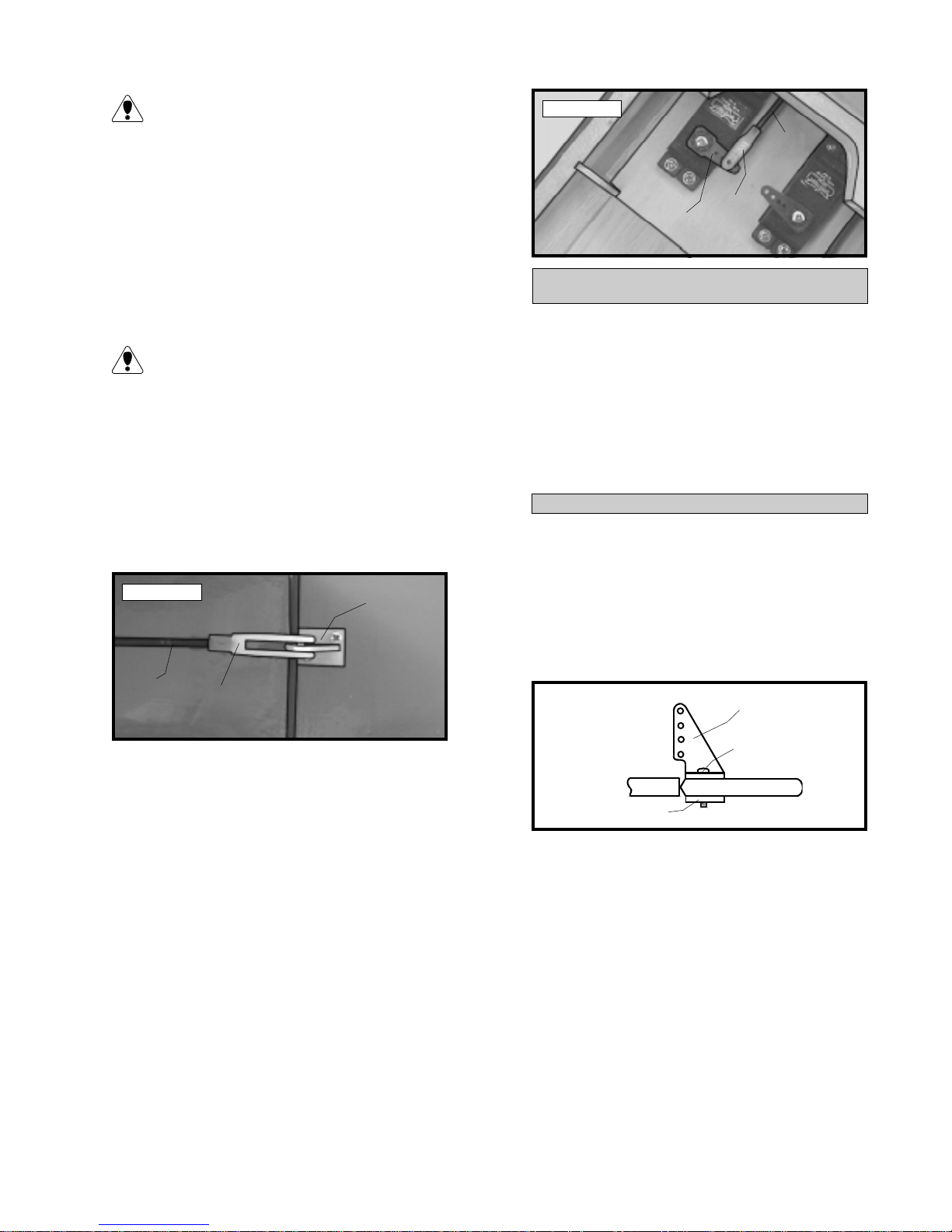
o 15) Thread one nylon clevis onto the threaded
wire. For security it should be threaded no less
than 5/16” onto the wire. Snap the clevis onto the
rudder control horn. See photo # 39 below.
Photo # 39
THREADED
ROD
NYLON
CLEVIS
CONTROL
HORN
Photo # 40
PUSHROD
WIRE
SERVO
ARM
SNAP
KEEPER
ELEVATOR PUSHROD
PARTS REQUIRED
o {1 } Wood Dowel (D-34)
o {1 } 2mm x 90mm Wire w/L-Bends Both Ends
o {2 } 2mm x 210mm Wire Threaded One End
o {2 } Nylon Clevis w/2mm I.D. Hole
o {1} Nylon Snap Keeper
o {2} Nylon Control Horns (short)
o { 2 } Nylon Control Horn Backplates
o { 4} 2mm x 15mm Machine Screws
INSTALLING THE ELEV A TOR CONTROL HORNS
o 1) The centerlines of the elevator control horns
are located on the bottom side of each elevator
half 1” out from the fuselage sides. Position the
control horns so the clevis attachment holes are directly in-line with the hinge lines. The control horns
should also be parallel with the hinge lines. See
figure # 11 below .
Figure # 1 1
CONTROL HORN
o 16) Locate a long servo arm and using wire
cutters, remove all but one of the arms. The the
remaining arm down to 3/8” long. Install the Lbend in pushrod wire into the outer hole in the
servo arm. Secure the wire in place using one
nylon snap keeper.
o 17) Using a couple of pieces of masking
tape, hold the rudder in neutral. With the rudder
and rudder servo in neutral, install the servo arm
onto the servo. The arm should be positioned
perpendicular to the fuselage sides and point to
the middle of the fuselage. Y ou can thread the
nylon clevis in further or back it out to achieve the
correct length.
o 18) When satisfied with the alignment, install
the servo arm set screw and remove the masking
tape from the rudder . See photo # 40 at top right.
MOUNTING SCREW
CONTROL HORN BASE
o 2) When satisfied with the alignment, use a
3/32” drill bit and the control horns as a guide
and drill the mounting holes through the elevator
halves.
o 3) Mount the control horns to the elevator
halves by inserting the 2mm x 15mm machine
screws through the control horn mounting bases,
through the elevator halves and into the backplates. Tighten the screws, but do not overtighten
them. Y ou do not want to crush the wood.
21
Page 22
ELEV A TOR PUSHROD ASSEMBL Y
o 4) Using a ruler, measure the pushrod dowel
(D-34). The dowel should be 9-3/4” long. If it is
longer, use a modeling knife and cut the dowel to
the proper length.
o 5) Using a ruler and a pen, measure in 1”
from only one end of the dowel and place a mark.
Using a 3/32” drill bit, drill a hole completely
through the dowel at this mark. Using a modeling
knife, cut a groove on each side of the dowel
from the hole out to the end of the dowel. See
figure # 12 below .
Figure # 12
CUT
GROOVES
CUT
GROOVES
1”
DRILL
HOLE
o 9) Using a ruler and a pen, measure in 2-1/4”
from the opposite end of the dowel and place a
mark. Using a 3/32” drill bit, drill a hole completely through the dowel at this mark. The hole
should be perpendicular to the first hole you drilled.
Use a modeling knife and cut a groove from the
hole out to the end of the dowel.
o 10) Trial fit the 2mm x 90 wire with L-bends
at both ends into the hole you just drilled. Use a
ruler and measure from the L-bend to the tips of
the threaded wires. The measurement should be
17-7/8”. If it is not, make any necessary adjustments until the proper measurement is achieved.
See photo # 41 below.
Photo # 41
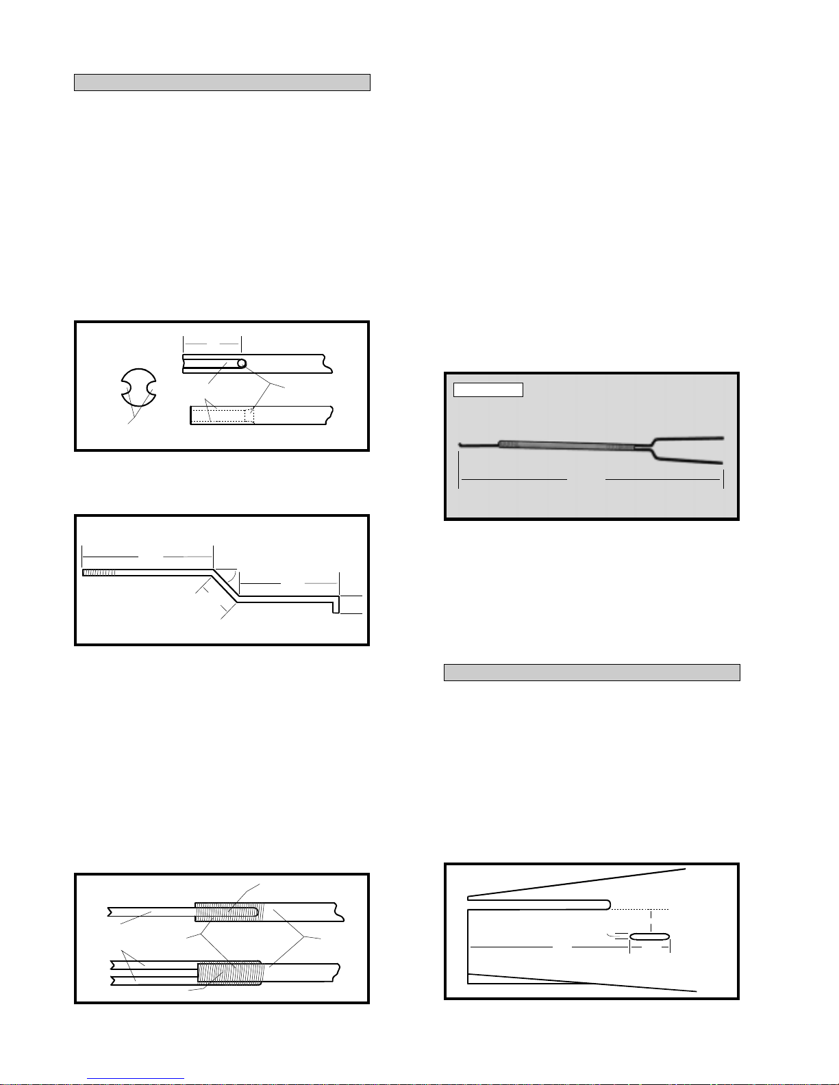
o 6) Using a pair of pliers, bend the remaining
two 2mm x 210mm threaded wires to the correct
dimension. See figure # 13 below .
Figure # 13
3-1/2”
FIGURE NOT TO SCALE
ELEVATOR PUSHROD WIRE
45º
7/
8”
(2pcs)
3-3/4”
1/8”
o 7) Install the 90º bend in one wire into each
side of the hole in the wood dowel. The wires
should lay in the grooves as well.
o 8) Holding the wires in place, apply a small
amount of Kwik Bond Thin C/A to the wires and
dowel. Allow the glue to cure, then wrap the
wires to the dowel using 1/2A Flying Line or similar thread. Apply more thin C/A to the thread,
wires and dowel and allow the glue to cure. The
wires should be solidly attached to the dowel.
See figure # 14 below .
Figure # 14
APPLY C/A
17-7/8”
o 11) Holding the wire in place, apply a small
amount of Kwik Bond Thin C/A to the wire and
dowel. Allow the glue to cure, then wrap the
wire to the dowel using 1/2A Flying Line or similar thread. Apply more thin C/A to the thread,
wire and dowel and allow the glue to cure. The
wire should be solidly attached to the dowel.
ELEV A TOR PUSHROD INST ALLATION
o 12) Using a ruler and a pen, mark the size
and the positions of the two elevator pushrod exits
and outline them onto both sides of the fuselage.
The pushrod exits are located on both sides of the
fuselage, 3/4” below the bottom surface of the horizontal stabilizer. The exits should be 3/32” tall and
1-3/16” long. The rear edge of the exits are located 4-7/8” forward of the rear edge of the fuselage. See figure # 15 below .
Figure # 15
NOT TO SCALE
PUSHROD
WIRES
THREAD
APPLY C/A
SIDE VIEW
TOP VIEW
DOWEL
22
3/32”
4-7/8” 1-3/16”
3/4”
MAKE EXITS ON
BOTH SIDES
Page 23
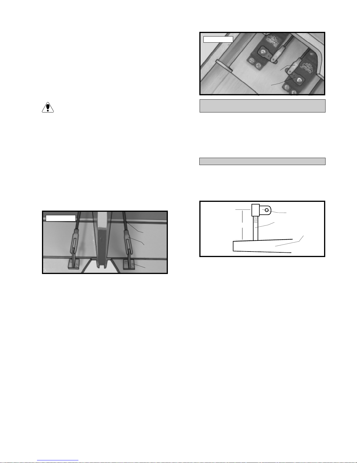
o 13) Using a modeling knife, cut out the pushrod exits at the locations marked.
o 14) Insert the elevator pushrod assembly,
threaded wires first, through the servo compartment and out the elevator pushrod exits in the
back of the fuselage.
Photo # 43
SNAP
KEEPER
SERVO
ARM
If you have trouble guiding the threaded
wires out the exit holes, drop a length of
thread through each exit slot and into the servo
compartment. Tie the thread to the ends of the
threaded wire and slowly pull the thread. The
thread will lead the pushrod wires out the exit
holes.
o 15) Thread one nylon clevis onto each
threaded wire. For security they should be
threaded no less than 5/16” onto the wires. Snap
the clevises onto the elevator control horns. See
photo # 42 below.
Photo # 42
RUDDER
REMOVED FOR
CLARITY
PUSHROD
WIRE
CLEVIS
CONTROL
HORN
o 16) Locate a long servo arm and using wire
cutters, remove all but one of the arms. Cut down
the remaining arm to 3/8” long. Install the L-bend
in the pushrod wire into the outer hole in the servo
arm. Secure the wire in place using one nylon
snap keeper.
AILERON LINKAGE
PARTS REQUIRED
o {2 } Nylon Clevises w/2mm I.D. Hole
o {2 } 2mm x 138mm Threaded Rod w/L-Bend
o {2} Nylon Snap Keepers
o {2} Nylon Adjustable Control Horns
INST ALLING THE AILERON LINKAGE
o 1) Thread one nylon adjustable control horn
onto each aileron torque rod. Thread them on
until they are 7/8” above the top surface of the
wing. See figure # 16 below .
Figure # 16
7/8”
o 2) Thread one nylon clevis at least 5/16” onto
each of the two 2mm x 138mm threaded rods
with L-bends.
o 3) With the aileron servo centered, install one
dual takeoff servo arm onto the servo. The arm
should be installed so it is parallel with the trailing
edge of the wing.
CONTROL HORN
TORQUE ROD
WING
o 17) Using a couple of pieces of masking
tape, hold the elevator halves in neutral. With the
elevator halves and elevator servo in neutral, install the servo arm onto the servo. The arm should
be positioned perpendicular to the fuselage sides
and point towards the middle of the fuselage. Y ou
can thread the nylon clevises in further or back
them out to achieve the correct length.
o 18) When satisfied with the alignment, install
the servo arm set screw and remove the masking
tape from the elevator halves. See photo # 43
at top right.
o 4) Use a couple of pieces of masking tape,
taped between the ailerons and the trailing edge
of the wing, to hold the two ailerons in neutral.
o 5) Snap the clevises onto the adjustable control horns. With the servo arm and ailerons centered, push the L-bends up through the outer holes
in the servo arm. Adjust the length of the wires
by turning the nylon clevises in or out until the
correct length is achieved. Hold the wires in place
using two nylon snap keepers. See photo # 44
at top right.
23
Page 24
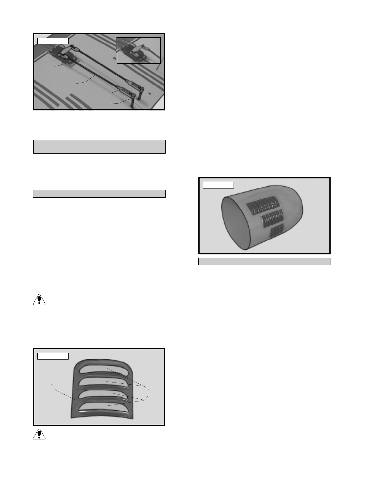
Photo # 44
SNAP
KEEPER
PUSHROD
WIRE
CLEVIS
CONTROL
HORN
o 6) When satisfied with the alignment, install
the servo arm set screw and remove the masking
tape from the ailerons.
COWL INSTALLATION
PARTS REQUIRED
o {1} Molded Fiberglass Cowling
o { 2 } Plastic Molded Cowl V ent Sets
o { 4} 2mm x 6mm Wood Screws
INST ALLING THE COWL VENTS
o 1) Using a Dremel Tool with a cutting disc
attachment, carefully cut out the six separate sections of the cowling that accept the molded cowl
vents. Carefully cut out each section along the
molded scribe lines in the cowl. Three sections
are located on each half of the cowl.
o 4) Using 220 grit sandpaper, roughen the fiberglass inside the cowl where the vents will be
glued in place. Also roughen the 1/8” lips around
each of the vents.
o 5) Trial fit each of the vents into the cowl.
The vents are installed from the inside of the cowl
and the holes in the rear of the vents should face
the rear of the cowl. Make any adjustments necessary to achieve a good fit.
o 6) When satisfied with the fit, mix up a generous amount of Kwik Bond 5 Minute Epoxy .
Carefully apply a thin layer to the lips surrounding
each vent. W orking one at a time, apply the epoxy and install the vents. Use masking tape to
hold the vents in place until the epoxy cures. See
photo # 46 below.
Photo # 46
o 2) Using a modeling knife, cut out each of
the six molded cowl vent sections. Leave about
1/8” of plastic around each section.
The vents will be glued from the inside of
the cowl. Leaving a 1/8” lip around each
section provides a good gluing surface.
o 3) Using a modeling knife, carefully cut out
the rear section of each vent. See photo # 45
below.
Photo # 45
COWL
VENT
CUT OUT
This is time consuming, however it will result in much better cooling of your engine
and is highly recommended.
INST ALLING THE COWL
o 7) Remove the carburetor and muffler from
the engine. Use plastic or masking tape to cover
the carburetor, muf fler and glow plug openings in
the engine to prevent dust from entering.
o 8) Trial fit the cowl onto the fuselage. When
aligned properly the back edge of the cowl should
be flush with the font of the cowl ring on the fuselage. Y ou may have to lightly sand the corners of
the plywood engine mounting box to allow the
cowl to slide on without binding. Locate and mark
the area of the cowl that needs to be removed for
engine cylinder head clearance using a pen.
o 9) Remove the cowl and make the cut out
using a Dremel T ool with a sanding drum attachment. Cut out a small amount at a time and trial
fit the cowl after each cut. Repeat until you are
satisfied with the cut out.
o 10) When satisfied with the fit of the cowl
slide it onto the fuselage and hold it in place with
masking tape.
24
Page 25
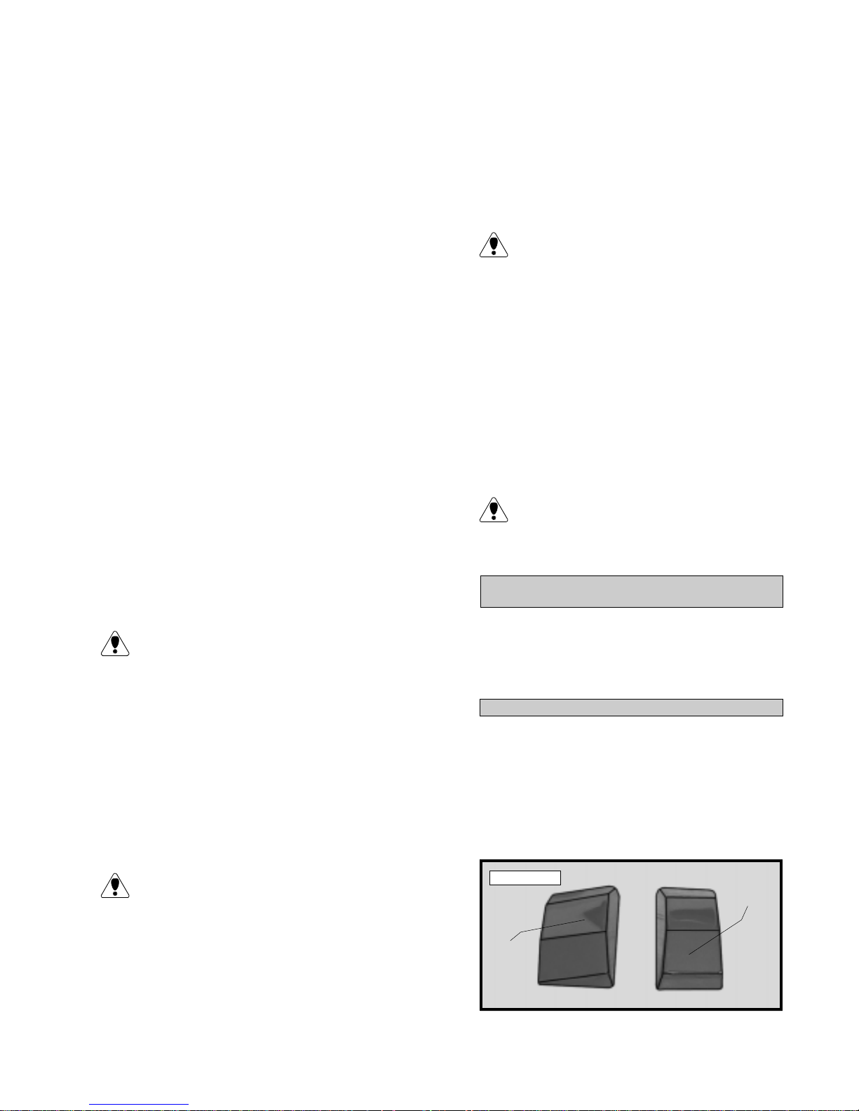
o 1 1 ) The cowl is held in place using four
2m m x 6mm wood screws threaded into four
preinstalled mounting blocks on the firewall. Use
a ruler and pen to locate and mark the mounting screw locations onto the cowl.
o 12) Using a 1/16” drill bit, drill four pilot
holes through the cowl and into the mounting
blocks at the locations you marked.
o 17) If using a Pitts Style muffler we highly
recommend cutting and air exit hole that is 1-1/2”
wide and 1-1/2” to 2” long. Locate the hole just
behind the hole you cut for the exhaust pipes to
exit the cowl. This will help cool the engine and
muffler assembly and prevent the engine from
overheating.
An air exit hole is also recommended even
if using a stock muffler .
o 13) Remove the cowl and enlarge the holes
in only the cowl using a 5/64” drill bit. Reinstall
the cowl and secure it in place using the four wood
screws.
o 14) Locate the areas of the cowl that need
to be removed for access to the high and low
speed needle valves and muffler assembly .
o 15) Remove the cowl and make these cutouts using a Dremel T ool with a cutting disc and
sanding drum attachment. Holes for the needle
valves can be cut using a drill bit. W e highly suggest the use of a Dubro Fuel Filler V alve to fuel
the airplane. This should be mounted to the cowling at this time also.
Because of the diameter of the cowl, it will
be likely you will need to use a needle valve
extension for the high speed needle valve. Make
this out of sufficient length 1.5mm wire and install
it into the end of the needle valve. Secure the
wire in place by tightening the set screw in the
side of the needle valve.
o 16) Install your muffler (stock or Pitt's Style)
and connect your fuel and pressure lines to the
fuel tank.
o 18) Once you are satisfied with the fit of the
cowl and all access holes have been cut, remove
the cowl and paint it with T opflite Gloss Clear #
TOPR7200 to prevent raw fuel from damaging
the paint.
o 19) After the clear coat has dried, connect
the fuel lines to the muffler, fuel filler valve and
carburetor . Reinstall the cowl and secure it in
place. Install the prop and spinner.
Depending on the pitch size of the propeller
you choose to use, it may not fit the cut outs
in the spinner . If necessary, you should relieve the
cut outs to fit your propeller using a modeling knife.
CANOPY INSTALLATION
PARTS REQUIRED
o {1} Clear Molded Canopy
o { 4} 2mm x 10mm Wood Screws
o {2} Plastic Molded Instrument Panels
INST ALLING THE INSTRUMENT PANELS
o 1) Using a modeling knife, carefully cut out
the front and rear instrument panels along the scribe
lines at the bottom edges.
o 2) Using a 220 grit sandpaper with a sanding block, sand the edges of both panels smooth
and straight. See photo # 47 below.
If you are using a two stroke engine with a
stock muffler a muffler extension will be necessary . No extension is necessary if using a four
stroke engine or a two stroke engine with an aftermarket Pitt's Style muffler (recommended).
25
Photo # 47
FRONT
PANEL
REAR
PANEL
Page 26
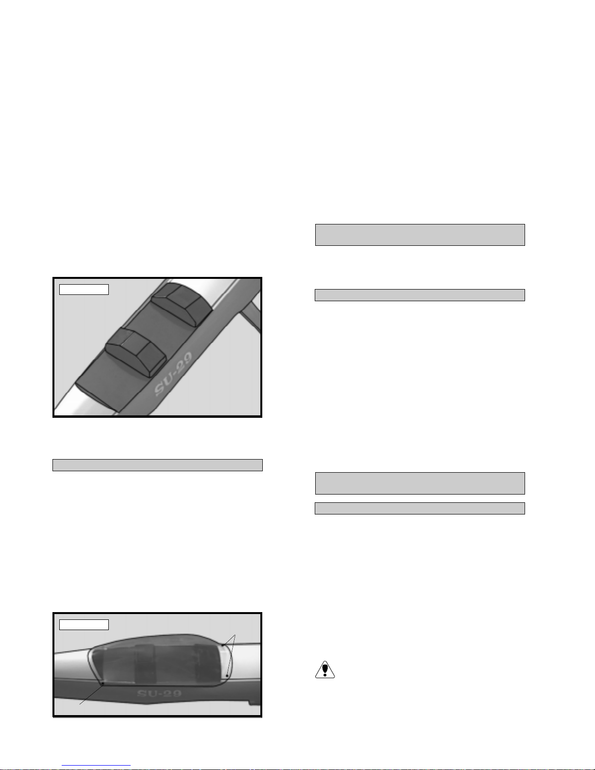
o 3) Trial fit the instrument panels in place on
the cockpit floor . The front edge of the forward
panel should fit up tight against the front of the
cockpit. The sides of the panel should be spaced
equally from the fuselage sides. The back edge
of the rear panel is located 3” forward from the
rear edge of the cockpit floor . It's sides should
also be equally spaced from the fuselage sides.
o 4) Use 220 grit sandpaper with a sanding
block and make any necessary adjustments to
the edges of the instrument panels until you are
satisfied with the fit.
o 5) When satisfied with the fit, glue the instrument panels in place using RC256 Canopy Glue.
Hold the panels in place with masking tape until the
glue completely cures. See photo # 48 below.
Photo # 48
o 10) Using a 3/32 drill bit, drill four mounting holes only through the canopy at the four locations you marked.
o 11 ) Apply a thin bead of RC256 Canopy
Glue to the perimeter of the canopy. Set the
canopy in place and secure using four 2mm x
10mm wood screws threaded into the fuselage.
Allow the glue to fully cure.
o 12) To give the canopy a better appearance
on the fuselage, we suggest using red, white and
black trim tape and detail the canopy to match
the fuselage.
DECAL APPLICATION
PARTS REQUIRED
o {1} Decal Set
APPL YING THE DECALS
o 1) Using scissors, cut out each of the
decals.
o 6) If you have purchased pilot assemblies
separately , detail and install them now, before installing the canopy .
INSTALLING THE CANOPY
o 7) Using a modeling knife or Lexan Canopy
Scissors, cut out the canopy along the molded
scribe lines.
o 8) Trial fit the canopy. When you have adjusted the canopy so it is straight, hold it in place
using a couple pieces of masking tape.
o 9) Using a pen, place a mark on both sides
of the canopy at the front and back. Use the photo
below for reference. See photo # 49 below.
Photo # 49
PLACE
MARK
o 2) To locate the decals, use the photo on
the box label or on the cover of this instruction
book. Clean the area where each decal will be
located using rubbing alcohol and a paper towel.
o 3) Remove the adhesive backing from the
decal and set the decal in place. Use your fingers
to squeeze out any trapped air under the decal.
The decals are fuel proof so they require no special sealer.
FINAL ASSEMBLY
INST ALLING THE RECEIVER AND BATTER Y
o 1) Plug the servo leads into the receiver . Plug
the aileron extension and switch that came with
your radio system into the receiver as well.
o 2) Wrap the receiver and battery pack in
foam rubber to protect them from vibration. Position the battery in the fuel tank compartment and
the receiver behind the fuel tank, next to the throttle
servo. Use extra foam pieces to hold them in
position.
PLACE MARK (BOTH SIDES)
When balancing the airplane you may need to
move the battery or receiver forward or aft to
achieve proper balance. In our test airplane, using a
Magnum XL .46 two stroke engine, the battery and
receiver were mounted as per step # 2.
26
Page 27
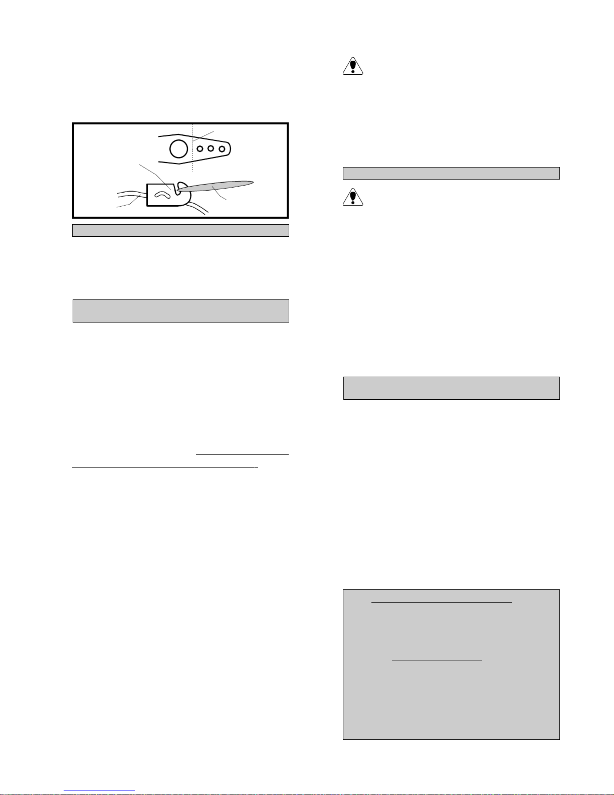
o 3) Using a 1/16” drill bit, drill a hole through
the side of the fuselage, opposite the muffler , for
the antenna to exit. Route the antenna out of the
fuselage and secure it to the vertical stabilizer using a rubber band. See figure # 17 below .
Figure # 17
MODIFIED
SERVO ARM
ANTENNA
INSTALLING THE SWITCH
CUT
TO VERTICAL
STAB
RUBBER BAND
o 4) Mount the switch to the fuselage side, opposite the muffler , at the middle of the servo compartment. Use the faceplate of the switch itself to
locate at make the necessary cutouts and holes.
Once you have flown and trimmed the Sukhoi,
the balance point can be moved forward or
aft 1/4” to change the flight performance. Moving
the balance point back will cause the Sukhoi to be
more responsive, but less stable. Moving the balance point forward will cause the Sukhoi to be
more stable, but less responsive. Do not fly the
Sukhoi beyond the recommended balance
range or an uncontrollable crash could result!
LA TERAL BALANCE
After you have balanced the Sukhoi on the
C.G. you must laterally balance it. Doing
this will help the airplane track better.
o 5) Turn the airplane upside down. Attach
one loop of heavy string to the engine crankshaft
and one to the tail wheel wire. With the wings
level carefully lift the airplane by the string. This
may require two people to make it easier .
BALANCE
o 1) It is critical that your airplane be balanced correctly . Improper balance will cause
your plane to lose control and crash. The cen-
ter of gravity is located 3-3/8” back from
the leading edge of the wing, at the fuselage sides. This location is recommended for
initial test flying and trimming. There is a 1/4”
margin forward and aft, but it is not recommended that the center of gravity be located any
further back than 3-5/8”. Balance the Sukhoi
upside down with the fuel tank empty.
o 2) Mount the wing to the fuselage. Using
a couple of pieces of masking tape, place them
on the top side of the wing 3-3/8” back from
the leading edge, at the fuselage sides.
o 3) Turn the airplane upside down. Place
your fingers on the masking tape and carefully lift
the plane.
o 4) If the nose of the plane falls, the plane is
nose heavy . T o correct this first move the battery
pack further back in the fuselage. If this is not
possible or does not correct it, stick small amounts
of weight on the fuselage under the horizontal stabilizer. If the tail of the plane falls, the plane is tail
heavy . T o correct this, move the battery and receiver forward or if this is not possible, stick
weight onto the firewall. When balanced correctly , the airplane should sit level or slightly nose
down when you lift it up with your fingers.
o 6) If one side of the wing falls, that side is
heavier than the opposite. Add small amounts of
lead weight to the bottom side of the heavier wing
half. Follow this procedure until the wing stays
level when you lift the airplane.
CONTROL THROWS
o 1) We highly recommend setting up the
Sukhoi using the control throws listed below . We
have listed control throws for both initial test flying/sport flying and aerobatic flying.
o 2) Turn on the radio system and with the trim
tabs on the transmitter in neutral, center the control surfaces by making adjustments to the clevises.
The servo arms should be centered also.
o 3) When the elevator, rudder and aileron
control surfaces are centered, use a ruler and
check the amount of the control throw in each
surface. The control throws should be mea-
sured at the widest point of each surface!
INITIAL FL YING/SPORT FL YING
Ailerons: 1/4” up 1/4” down
El eva tor : 5/16” up 5/16” down
Rudder: 3/4” right 3/4” left
AEROBATIC FL YING
Ai le ron s: 3/8” up 3/8” down
Elevator: 5/8” up 5/8” down
Rudder: 1-1/4” right 1-1/4” left
Do not use the aerobatic settings for initial test flying or sport flying.
27
Page 28

o 4) By moving the position of the clevis at the
control horn toward the outermost hole, you will
decrease the amount of throw of that control surface. Moving the clevis toward the control surface
will increase the amount of throw .
FLIGHT PREPARATION
o 1) Check the operation and direction of the
elevator, rudder , ailerons and throttle.
o A) Plug in your radio system per the
manufacturer's instructions and turn everything on.
o C) The ailerons should move 1/4” up
and 1/4” down from center . T o adjust the amount
of aileron throw , first move the pushrods on the
servo arm. Move the pushrods toward the center of the servo for less movement. Move the
pushrods farther away from the center of the
servo for more movement. If enough movement
cannot be achieved in this manner, thread the
adjustable torque rod horns farther down the
torque rods, toward the wing. It is important
that both ailerons move the same amount, both
up and down.
o B) Check the elevator first. Pull back
on the elevator stick. The elevator should go up.
If it does not, flip the servo reversing switch on
your transmitter to change the direction.
o C) Check the rudder . Looking from behind the airplane, move the rudder stick to the right.
The rudder should move to the right. The tail wheel
should move to the right as well. If it does not, flip
the servo reversing switch on your transmitter to
change the direction.
o D) Check the throttle. Moving the
throttle stick forward should open the carburetor barrel. If it does not, flip the servo reversing
switch on your transmitter to change the direction.
o E) From behind the airplane, look at the
aileron on the right wing. Move the aileron stick
to the right. The aileron should move up and the
other aileron should move down. If it does not,
flip the servo reversing switch on your transmitter to change the direction.
o 2) Check Control Surface Throw .
o D) Once the control throws and move-
ments are set, tubing must be added to the clevises to ensure they do not release in the air. A
length of clear tubing was provided in the kit for
this. Cut it into the 1/4” pieces and slip one piece
over each clevis.
PREFLIGHT CHECK
o 1) Completely charge your transmitter and receiver batteries before your first day of flying.
o 2) Check every bolt and every glue joint in
the Sukhoi to ensure everything is tight and well
bonded. This should include all of the control
surface hinges as well.
o 3) Double check the balance of the airplane.
Do this with the fuel tank empty .
o 4) Check the control surfaces. All should
move in the correct direction and not bind.
o 5) If your radio transmitter is equipped with
dual rate switches double check that they are on
the low rate setting for your first few flights.
o A ) The Rudder should move 3/4” left
and 3/4” right from center . If it moves too far ,
move the pushrod clevis to a hole in the rudder
horn away from the rudder . Do the opposite if
there is not enough throw .
o B) The elevator should move 5/16” up
and 5/16” down from center. If it moves too
far, move the pushrod clevis to a hole in the elevator horn away from the elevator . Do the opposite if there is not enough throw .
o 6) Check to ensure the control surfaces are
moving the proper amount for both low and high
rate settings.
o 7) Check the receiver antenna. It should be
fully extended and not coiled up inside the fuselage.
o 8) Properly balance the propeller. An out
of balance propeller will cause excessive vibration which could lead to engine and/or airframe
failure.
28
Page 29

FLYING
NOTES
The Sukhoi is designed for those pilots who are
experienced in flying sport models. It is in no
way a trainer . If you do not feel comfortable that
you are able to test fly the airplane don't hesitate
to ask someone for some help getting it tested
and trimmed out. T ypically, aerobatic airplanes
such as the Sukhoi, require some different flying
techniques that you might not be familiar with. It
is very important to let the airplane get up to fly-
ing speed before lifting off. Pulling the plane off
the ground too fast will cause the airplane to stall
and crash. Y ou should allow the plane to roll out
until the tail is completely off the ground and fly-
ing. Allow the airplane to roll out about 50 feet
more and gently pull it off the ground and into a
shallow climb out.
In the air, the plane flies like any other sport aero-
batic plane. Loops, rolls, low passes and most
all other maneuvers are all possible. Because of
the sometimes excessive control throws used for
aerobatics you must be aware of high speed stall-
ing. This is when the airplane is at full power and
too much up elevator is input at once. It causes
the airplane to snap. T o prevent this, make sure
the elevator is set up to our recommended test
flying and sport flying settings. When set up to
aerobatic settings, be gentle on the elevator .
When it is time to land always bring the airplane
in with a small amount of power. It is not a good
habit to just chop the throttle and dive the air-
plane to the ground. Just like the real airplanes,
gradually reduce power along with altitude and
speed. When you are about 2-3 feet off the
ground, reduce power to idle and gently let the
airplane settle onto the runway . Be careful not to
over control.
Happy Landings!
____________________________________________________
______________________________________________
______________________________________________
______________________________________________
_____________________________________________
______________________________________________
______________________________________________
_____________________________________________
______________________________________________
____________________________________________________
______________________________________________
______________________________________________
______________________________________________
_____________________________________________
______________________________________________
______________________________________________
_____________________________________________
______________________________________________
____________________________________________________
______________________________________________
______________________________________________
______________________________________________
_____________________________________________
______________________________________________
______________________________________________
_____________________________________________
______________________________________________
____________________________________________________
______________________________________________
______________________________________________
______________________________________________
_____________________________________________
______________________________________________
______________________________________________
_____________________________________________
______________________________________________
______________________________________________
____________________________________________________
______________________________________________
______________________________________________
______________________________________________
_____________________________________________
______________________________________________
______________________________________________
_____________________________________________
29
Page 30

TRIM CHART
After you have test flown and done the initial trim changes to the aircraft, use the Trim Chart below to begin
trimming your airplane. Following and adhering to this chart will result in the ability to diagnose trim problems
and correct those problems using the simple adjustments shown below . Making these observations and
related corrections will result in a truer, straighter and better flying airplane.
TRIM FEA TURE MANEUVER OBSERV A TION CORRECTION
Control Centering Fly general circles and Try for hands off straight Readjust linkages so Tx
random maneuvers. and level flight. trims are centered.
Control Throws Fly random maneuvers. A) Too sensitive, jerky If A) Change linkages to
controls. reduce throws.
B) Not sufficient control. If B) Increase throws.
Engine Thrust Angle* From straight flight, A) Airplane continues If A) Thrust is correct.
chop throttle quickly. level path for short
distance.
B) Airplane pitches nose up. If B) Decrease downthrust.
C) Airplane pitches nose If C) Increase downthrust.
down.
Center of Gravity From level flight, roll A) Continues in bank for If A) Trim is good.
Longitudinal Balance to 45º bank and moderate distance.
neutralize controls. B) Nose pitches up. If B) Add nose weight.
C) Nose drops. If C) Remove nose weight.
Y aw** Into wind, do inside A) Wings level throughout. If A) Trim is correct.
loops using only elevator. B) Yaws to right in both If B) Add left rudder trim.
Repeat tests doing inside and outside loops.
outside loops from C) Y aws to left in both If C) Add right rudder trim.
inverted entry. inside and outside loops.
D) Y aws to right on inside, If D) Add left aileron trim.
and left on outside loops.
E) Y aws left on inside, and If E) Add right aileron trim.
right on outside loops.
Lateral Balance Into wind, do tight A) Wings are level and If A) Trim is correct.
inside loops. plane falls to either side.
B) Falls off to left in loops. If B) Add weight to right
Worsens as loops tighten. wing tip.
C) Falls off to right in loops. If C) Add weight to left
Worsens as loops tighten. wing tip.
Aileron Rigging W ith wings level, pull A) Climb continues along If A) Trim is correct.
to vertical climb and same path.
neutralize controls. B) Nose tends to go to If B) Raise both ailerons
inside loop. very slightly.
C) Nose tends to go to If C) Lower both ailerons
outside loop. very slightly.
*Engine thrust angle and C.G. interact. Check both.
**Y aw and lateral balance produce similar symptoms. Note that the fin may be crooked. Make certain both elevator
halves are even with each other and produce the same amount of control throw. Right and left references are from the rear
of the plane, as if you were in the cockpit.
30
Page 31
** PRODUCT EVALUATION SHEET **
T elling us what you like and don't like determines what model kits we make and how we make them. W e
would appreciate it if you would take a few minutes of your time to answer the following questions about
this kit and your modeling interests. Simply fold this form on the dotted lines, seal with tape and mail it to
us. Do not use staples and make sure our address faces out.
1.) Kit: Sukhoi 40 (# 123668)
2.) Where did you learn about this kit?
o Magazine Ads o Friend
o Hobby Shop o Other
o Internet
3.) What influenced you the most to buy this kit?
o Magazine Ads o Price
o T ype of Model o Box Art
o Recommendation o Other__________
o Internet
4.) Did you have any trouble understanding
the written instructions? If yes, please
explain.
o Yes o No
__________________________________
__________________________________
__________________________________
__________________________________
5.) Did you have any trouble understanding
any of the photographs in the instructions?
If yes, please explain.
o Yes o No
__________________________________
__________________________________
__________________________________
__________________________________
6.) W ere any of the kit parts:
o Damaged o Wrong Size
o Missing o Wrong Shape
If you checked any of the boxes above,
please list the parts below:
__________________________________
__________________________________
7.) W as any of the model's assembly difficult
for you? If yes, please explain.
__________________________________
__________________________________
__________________________________
8.) What did you like most about this kit?
o Assembly Manual o Parts Fit
o Hardware Supplied oOther_________
__________________________________
__________________________________
9.) What did you like least about this kit?
o Assembly Manual o Parts Fit
o Hardware SuppliedoOther_________
__________________________________
__________________________________
10.) Are you satisfied with the finished model?
o Yes o No
If no, please explain.
_________________________________
_________________________________
_________________________________
11.) How does this kit compare to similar kits
by other manufacturers?
o Better Than o As Good
o Not as Good
12.) Please list any other comments or
suggestions you have.
_________________________________
_________________________________
_________________________________
_________________________________
31
Page 32
Fold along dotted line
Global Hobby Distributors
Attn: Customer Service Department
18480 Bandilier Circle
Fountain V alley , CA. 92728
Fold along dotted line
Place
Stamp
Here
32
 Loading...