


Model Tech makes 3D more fun with more performance. The no-compromise Magic Formula 3D ARF is a true aerobatic machine.
Two years and thousands of R&D hours went into the making of this unique and beautiful flying machine.
The Magic Formula 3D ARF is drawn in 3D-CAD, then each kit is cut on the latest large-footprint laser cutters and assembled by
master craftsmen in precision-made jigs. Finally, after sanding, test-fitting and checking alignment, each airplane is hand-covered
using real iron-on covering.
In the air, you'll find the Magic Formula 3D ARF to have the performance envelope you're looking for in a larger 3D-style aircraft.
Slow speed is amazing, transition to hover is easy and high alpha maneuvers are stable, and with the right powerplant, you'll be
amazed at the vertical performance. Rolling Harriers, hovering, flat spins, Blenders and torque rolls...you'll look like a world-class
pro flying your own Magic Formula 3D ARF.
INSTRUCTIONS FOR FINAL ASSEMBLY
The Model Tech Magic Formula 3D ARF is distributed
exclusively in the USA by Global Hobby Distributors
✦✦
✦IMPORTANT
✦✦
and in the U.K. by YT International
All contents copyright © 2004, Global Hobby
Distributors Version V1.0 December 2004
✦✦
✦ The Model Tech Magic Formula 3D ARF is not intended for inexperienced pilots. It is not a trainer. If you are
✦✦
not comfortable flying high-performance aerobatic aircraft, we strongly suggest returning the airplane (brand new, in the box with
all original packaging and your dated sales receipt) to the place of purchase.
Magic Formula 3D ARF Specifications:
●
Wing Span: 60 Inches (1524mm)
●
Wing Area: 1027 Square Inches (66.3dm2)
●
Length: 64 Inches (1630mm)
●
Weight RTF: 6.1 - 7.7 Pounds (2.75-3.5kg)
●
Wing Loading: 13.6-17.25 oz/sq in (41-52 g/sqdm)
●
Functions: Ailerons, Elevator, Rudder and Throttle
●
Engine Required: .46 - .61 Two-Stroke or .61-.70 Four-Stroke
●
Radio Required: 4 Channel or More w/6 Standard BB Servos
1
Kit Product Number 123771

TABLE OF CONTENTS
Safety Warning ...................................................................................... 2
Introduction ............................................................................................ 3
Customer Service Information ..............................................................3
Section 1: Our Recommendations ....................................................... 4
Section 2: Tools and Supplies Required ............................................. 5
Section 3: A Note About Covering ....................................................... 5
Section 4: Kit Contents ........................................................................ 6
Section 5: Wing Assembly ................................................................... 7
Section 6: Wing Mounting ..................................................................10
Section 7: Belly Pan Installation ........................................................ 12
Section 8: Stabilizer Installation.........................................................13
Section 9: Control Surface Hinging ................................................... 17
Section 10: Tail Skid Installation ........................................................19
Section 11: Landing Gear Installation ................................................ 20
Section 12: Engine Installation .......................................................... 23
Section 14: Fuel Tank Assembly and Installation ..............................27
Section 15: Elevator Control System Installation ..............................30
Section 16: Rudder Control System Installation ............................... 32
Section 17: Aileron Control System Installation ................................34
Section 18: Cowling Installation ......................................................... 36
Section 19: Canopy Installation .........................................................38
Section 20: Final Assembly ............................................................... 39
Section 21: Balancing the Magic Formula 3D ARF .......................... 40
Section 22: Lateral Balancing the Magic Formula 3D ARF ..............40
Section 23: Aircraft Setup Information ...............................................41
Section 24: Control Throws................................................................42
Section 25: Computer Radio Setup and 3D Control Throws ............42
Section 26: Preflight Check and Safety ............................................. 43
Section 27: Magic Formula 3D ARF Flight-Trimming Chart ............. 44
Section 28: Replacement Parts ......................................................... 45
Section 13: Throttle Control System Installation ............................... 24
Product Evaluation Sheet ...................................................................47
Check out our website for more information on
this and other exciting Model Tech products!
http://modeltech.globalhobby.com
SAFETY WARNING
This R/C airplane is not a toy! If misused or abused, it can cause serious bodily injury and/or damage to property. Fly only in open
areas and preferably at a dedicated R/C flying site. We suggest having a qualified instructor carefully inspect your airplane before
its first flight. Please carefully read and follow all instructions included with this airplane, your radio control system and any other
components purchased separately.
FOR YOUR INFORMATION
To make your modeling experience totally enjoyable, we recommend that you get experienced, knowledgeable help with assembly and during
your first flights. Your local hobby shop has information about flying clubs in your area whose membership includes qualified instructors. If there
is no hobby shop in your area, we recommend that you contact the AMA at the address below. They will be able to help you locate a flying field
near you.
Academy of Model Aeronautics
5151 East Memorial Drive
Muncie IN 47302-9252
(800) 435-9262
www.modelaircraft.org
Model Tech guarantees this kit to be free from defects in both material and workmanship at the date of purchase. This does not cover any
component parts damaged by use, misuse or modification. In no case shall Model Tech's liability exceed the original cost of the
purchased kit.
In that Model Tech has no control over the final assembly or material used for final assembly, no liability shall be assumed for any damage
resulting from the use by the user of the final user-assembled product. By the act of using the final user-assembled product, the user accepts all
resulting liability.
OUR GUARANTEE
2

INTRODUCTION
Thank you for purchasing the Model Tech Magic Formula 3D ARF. Before completing the final assembly of your new
airplane, please carefully read through this instruction manual in its entirety. Doing so will ensure your success the first
time around!
MODEL TECH MAGIC FORMULA 3D ARF FEATURES
●
Prebuilt from High-Quality Balsa and Light Plywood
●
Detailed, Laser-Cut Parts to Maximize Weight Reduction
●
Precovered with Real Iron-On, Heat-Shrink Covering Material
●
Durable Aluminum Main Landing Gear Bracket
●
Prepainted Molded Fiberglass Cowling
●
Dual Aileron Servos, Dual Elevator Servos and Pull-Pull Rudder Pushrods for Solid Control Response
●
Includes a High-Quality Hardware Package
●
Fast and Easy Assembly - Over 90 High-Resolution Digital Photos and Drawings to Guide You
This instruction manual is designed to guide you through the entire assembly process of your new airplane in the least amount of
time possible. Along the way you'll learn how to properly assemble your new airplane and also learn tips that will help you in the
future. We have listed some of our recommendations below. Please read through them before beginning assembly.
●
Please read through each step before beginning assembly.
You should find the layout very complete and straightforward.
Our goal is to guide you through assembly without any of the
headaches and hassles that you might expect.
●
There are check boxes next to each procedure. After you
complete a procedure, check off the box. This will help prevent
you from losing your place.
●
Cover your work table with brown paper or a soft cloth, both
●
Keep a couple of small bowls or jars handy to put the small
parts in after you open the accessory bags.
●
We're all excited to get a new airplane in the air, but take your
time. This will ensure you build a straight, strong and great
flying airplane.
●
If you come across this symbol ☞, it means that this is an
important point or an assembly hint.
to protect the table and to protect the parts.
CUSTOMER SERVICE INFORMATION
If you should find a part missing or damaged, or have any questions about assembly, please contact us at the address below:
In the USA:
Global Services
18480 Bandilier Circle
Fountain Valley, CA 92708
Phone: (714) 963-0329
Fax: (714) 964-6236
Email: service@globalhobby.net
In the United Kingdom:
YT International
15 Parkstone Closere
Shelfield
Walsall
West Midlands
WS4 1QW
Phone/Fax: 01922-684425
Email: inquiries@ytinternational.co.uk
www.ytinternational.co.uk
CHECK IT OUT! We urge you to come check out our website at http://globalservices.globalhobby.com. There you will find public message
boards frequented by other Model Tech product owners and the Model Tech support staff. This is a great place to learn about new products,
get help and suggestions for your current Model Tech products or just simply hang out and chat with people that share your same interests.
To enable us to better serve your needs, please include your email address with any correspondence you send to us. Your email
address will be added to our Customer Service Database so you will automatically receive free updates and tech notices for your
particular product. You will also receive repair status updates (if applicable) and other important information about your product
as it becomes available.
IMPORTANT INFORMATION ABOUT YOUR EMAIL ADDRESS
Global Hobby Distributors will not disclose the information it collects to outside parties. Global Hobby Distributors does not sell,
trade, or rent your personal information to others . Your privacy is important to us.
3

SECTION 1: OUR RECOMMENDATIONS
This section describes our recommendations to help you in deciding which types of accessories to purchase for your new
Model Tech Magic Formula 3D ARF. Please read through this entire section very carefully. We have provided you with tips
and recommendations that, if followed, will result in a great flying airplane. Failure to follow our recommendations may
result in a poor flying airplane.
What Engine Should I Use?
The airplane is designed to use a .46- .61 size two-stroke engine or a .61 - .70 size four-stroke engine.
The airplane flies well using engines within the recommended size ranges, although for the best
aerobatic performance we suggest using an engine at the upper end of the size range. For 3D-style
flying, we've found that the airplane flies best when matched with a lightweight,
yet powerful engine, such as the Magnum XL .70 four-stroke engine. For this
style of flying, we suggest using a large diameter, low pitch propeller suited for
your engine.
Whether you're using a two-stroke engine or a four-stroke engine, the
engine will be mounted inverted. The airplane has been designed to
allow the fuel tank to sit lower than normal to help prevent flooding and erratic engine tuning. Your
engine's stock muffler will be able to be used, regardless of the type of engine chosen.
If you're flying at higher altitudes, we recommend using an engine at the high end of the size range.
What Radio System and Servos Should I Use?
To get the most out of the airplane, we suggest using a four or more channel computer
radio system with mixing capabilities. Since there are two separate aileron servos
used, they can be plugged separately into the receiver, allowing you the capability of
flaperon and spoileron mixing, differential mixing and flaperon/spoileron to elevator
mixing. Because of the large control surfaces, using ball bearing servos is a must. For
crisp, positive control, we suggest using high-quality, dual ball bearing servos with a
minimum of 45-55oz/in of torque on the flight control surfaces. For throttle control, a
standard ball bearing servo can be used. Although you would lose mixing capabilities, the airplane can be flown using a basic
four-channel radio control system. If you do this, you will need to use a servo Y-Harness to join the two aileron servos together.
The airplane uses two separate elevator servos that are mounted offset, so no servo reverser is necessary. You will, however, need
a standard Y-Harness to connect the servos together.
What Else Do I Need?
There really isn't much else that you'll need to finish the airplane. Most of the hardware is included
in the kit, so about the only thing else you'll need is a remote fueling valve, four servo extension
leads and two Y-Harnesses. You'll also need typical modeling supplies, such as foam rubber to
protect your receiver and battery, and fuel tubing.
Here's a List of What We Used to Finish Our Magic Formula 3D ARF
QTY. 1 210945 Magnum XL .70RFS Four-Stroke Engine
QTY. 1 609288 APC 13 x 6 Composite Propeller
QTY. 5 759573 Hitec HS-475HD Deluxe Ball Bearing Servos
QTY. 1 444104 Cirrus CS-36 Standard Servo
QTY. 4 444713 Cirrus 12" Servo Extensions
QTY. 1 115559 Thunderbolt # 3 Performance Glow Plug
QTY. 1 237500 Magnum Fueling Valve
QTY. 1 115923 Global XX Silicone Fuel Tubing
QTY. 1 868638 Dubro 1/4" Protective Foam Rubber
QTY. 1 867903 Dubro 3/8" Heat-Shrink Tubing
✦✦
✦IMPORTANT
✦✦
connector. The part number for the Hitec servos and the Cirrus servo extensions are compatible with Hitec and JR radio control systems. These
items are also available with connectors that are compatible with Futaba and Airtronics radio control systems.
✦✦
✦ The part number for the Cirrus servo is compatible with all name-brand radio control systems. This servo uses a universal
✦✦
4

SECTION 2: TOOLS AND SUPPLIES REQUIRED
The tools and supplies listed below will be necessary to finish the assembly of your new Model Tech Magic Formula 3D ARF. We
suggest having these items on hand before beginning assembly.
❑ Kwik Bond Thin C/A # 887500
❑ Kwik Bond Thick C/A # 887510
❑ Kwik Bond 5 Minute Epoxy # 887560
❑ Kwik Bond 30 Minute Epoxy # 887565
❑ Kwik Bond C/A Debonder # 887545
❑ Pacer Formula 560 Canopy Glue # 339176
❑ Wilhold Silicon Sealant # 335407
❑ Pacer Z-42 Blue Threadlocker # 339162
❑ #1 & #2 Phillips Head Screwdrivers
❑ 3mm Hex Wrench
❑ Wire Cutters
❑ Needle Nose Pliers
❑ Magnum Z-Bend Pliers # 237473
❑ Adjustable Wrench (2)
❑ Excel Modeling Knife # 692801
❑ Scissors
❑ Electric Drill
❑ Assorted Drill Bits
❑ Ernst Airplane Stand # 223977
❑ Ruler
❑ Pencil
❑ Dubro T-Pins # 567677
❑ Rotary Tool w/Cutting Disc & Sanding Drum
❑ Builder's Triangle
❑ 220 Grit Sandpaper w/Sanding Block
❑ Masking Tape
❑ Paper Towels
❑ Waxed Paper
❑ Rubbing Alcohol
❑ NHP Epoxy Mixing Sticks # 864204
❑ NHP Epoxy Mixing Cups # 864205
❑ Global Heat Gun # 360920
❑ Global Heat-Sealing Iron # 360900
SECTION 3: A NOTE ABOUT COVERING
The covering material used on the Model Tech Magic Formula 3D ARF is real iron-on, heat-shrink covering material. It is
possible with heat and humidity changes that the covering on your airplane may wrinkle or sag. This trait is inherent in all
types of heat-shrink material. To remove any wrinkles that might be visible you will need to use a heat-sealing covering iron.
Follow this simple procedure to remove the wrinkles:
❑ Plug in and turn on the sealing iron to the medium-high temperature setting. Allow the sealing iron to heat up for approximately
5 - 7 minutes.
❑ After the sealing iron has reached temperature, lightly apply the sealing iron to the wrinkled section of the covering. Move the
sealing iron slowly over the wrinkled section until the covering tightens and the wrinkles disappear.
✦✦
✦IMPORTANT
✦✦
it will return to its normal color.
If the color layer smears from any of the seams the temperature of the sealing iron is too hot. Turn the temperature dial down
☞
and wait about 5 minutes for the sealing iron to adjust to the lower temperature. You can remove any excess color streaks using a
paper towel soaked with a small quantity of Acetone.
PRO TIP
for any length of time. The extreme heat could distort the molded parts and/or cause the covering material to wrinkle and possibly
damage the fragile components of the radio control system.
✦✦
✦ You will notice that the color of the covering will darken when it is heated. When the covering cools back down,
✦✦
We do not suggest storing your airplane in an extremely hot environment (like the back of your car in direct sunlight)
✦✦
✦WARNING
✦✦
✦✦
✦ The fiberglass cowling on your Magic Formula 3D ARF is painted. The blow-molded wheel pants and canopy are
✦✦
made from plastic. Do not use any harsh chemical cleaners, such as Acetone, to clean the painted or plastic surfaces. Use of
rubbing alcohol is okay and will not damage the paint or the plastic.
5

SECTION 4: KIT CONTENTS
We have organized the parts as they come out of the box for easier identification during assembly. Before you begin assembly,
group the parts as we list them below. This will ensure that you have all of the parts before you begin assembly and it will also help
you become familiar with each part.
If you find any parts missing or damaged, please contact us as soon as possible,
using the Customer Service Information on page # 3.
AIRFRAME ASSEMBLIES
❑ (1) Fuselage
❑ (1) Right Wing Panel w/Aileron
❑ (1) Left Wing Panel w/Aileron
❑ (1) Horizontal Stabilizer w/Elevator Halves
❑ (1) Vertical Stabilizer w/Rudder
LANDING GEAR ASSEMBLY
❑ (1) Aluminum Landing Gear Bracket
❑ (2) Molded Wheel Pants
❑ (2) Main Gear Wheels
❑ (2) M4 x 35mm Threaded Axles
❑ (3) M4 x 16mm Machine Screws
❑ (4) M4 Lock Nuts
❑ (2) Nylon Spacers
❑ (2) M2 x 10mm Flange-Head Wood Screws
❑ (13) M4 Flat Washers
AILERON CONTROL SYSTEM
❑ (2) 3-1/8" Threaded Wires w/90º Bends
❑ (2) Nylon Control Horns w/Backplates
❑ (2) Nylon Clevises
❑ (2) Nylon 90º Snap-Keepers
❑ (4) M2 x 16mm Machine Screws
❑ (8) C/A-Style Hinges
ELEVATOR CONTROL SYSTEM
❑ (2) 6-3/8" Threaded Wires w/90º Bends
❑ (2) Nylon Control Horns w/Backplates
❑ (2) Nylon Clevises
❑ (2) Nylon 90º Snap-Keepers
❑ (4) M2 x 12mm Machine Screws
❑ (6) C/A-Style Hinges
ENGINE MOUNT ASSEMBLY
❑ (2) Engine Mounting Beams
❑ (4) M4 x 20mm Socket-Cap Screws
❑ (4) M4 x 25mm Socket-Cap Screws
❑ (4) M4 Lock Nuts
❑ (12) M4 Flat Washers
RUDDER CONTROL SYSTEM
❑ (2) 38-1/2" Threaded Wires w/90º Bends
❑ (2) Nylon Control Horns (w/o Backplates)
❑ (2) Nylon Clevises
❑ (2) Nylon 90º Snap-Keepers
❑ (4) M2 x 12mm Machine Screws
❑ (4) M2 Flat Washers
❑ (4) M2 Hex Nuts
❑ (3) C/A-Style Hinges
THROTTLE CONTROL SYSTEM
❑ (1) 13-1/4" Plain Wire w/Z-Bend
❑ (1) Adjustable Pushrod Connector w/Machine Screw & Nut
TAIL SKID ASSEMBLY
❑ (1) Prebent Tail Skid
❑ (2) Nylon Mounting Straps
❑ (4) M2 x 10mm Wood Screws
FUEL TANK ASSEMBLY
❑ (1) 320cc Fuel Tank
❑ (1) Large Diameter Metal Plate
❑ (1) Small Diameter Metal Plate
❑ (1) Neck-Reinforcement Ring
❑ (1) Rubber Stopper
❑ (1) Fuel Pick-Up "Clunk"
❑ (1) M3 x 20mm Machine Screw
❑ (1) Silicone Fuel Tubing
❑ (3) Aluminum Tubing
MISCELLANEOUS FUSELAGE PARTS
❑ (1) Belly Pan
❑ (1) Molded Cowling
❑ (1) Spinner Assembly w/Backplate & Screws
❑ (1) Molded Canopy
❑ (4) M3 x 5mm Wood Screws
❑ (1) Clear Vinyl Tubing
❑ (1) Decal Set
6
Continued On Next Page
☛☛
☛
☛☛

MISCELLANEOUS WING PARTS
❑ (1) Plywood Wing Joiner (W34)
❑ (1) Plywood Wing-Screw Doubler (W35)
❑ (2) M4 x 40mm Machine Screws
❑ (2) M4 Flat Washers
A complete replacement parts list, along with part numbers for ordering convenience,
SECTION 5: WING ASSEMBLY
YOU'LL NEED THE FOLLOWING PARTS FROM THE KIT:
To convert inches into millimeters:
Inches x 25.4 = mm
To convert millimeters into inches:
Millimeters / 25.4 = in
can be found on page # 44.
❑ (1) Right Wing Panel w/Aileron
❑ (1) Left Wing Panel w/Aileron
YOU'LL NEED THE FOLLOWING TOOLS AND SUPPLIES:
❑ Kwik Bond 30 Minute Epoxy
❑ # 1 Phillips Head Screwdriver
❑ Excel Modeling Knife
❑ Electric Drill
❑ 1/16" Drill Bit
❑ Ruler
❑ Pencil
STEP 1: INSTALLING THE AILERON SERVOS
❑ Remove the aileron and hinges from one wing panel and set them aside.
❑ Install the rubber grommets and brass collets onto one aileron servo,
making sure to install the collets with the flanges toward the bottom of
the servo.
❑ Plug one 12" servo extension onto the aileron servo lead.
❑ To prevent the plugs from pulling apart during assembly, or worse,
during flight, secure the plugs together, using a short piece of 3/8"
diameter heat-shrink tubing. Use a heat gun to shrink the tubing tight.
❑ (1) Plywood Wing Joiner (W34)
❑ 220 Grit Sandpaper w/Sanding Block
❑ Masking Tape
❑ Paper Towels
❑ Rubbing Alcohol
❑ NHP Epoxy Mixing Sticks
❑ NHP Epoxy Mixing Cups
❑ Global Heat Gun
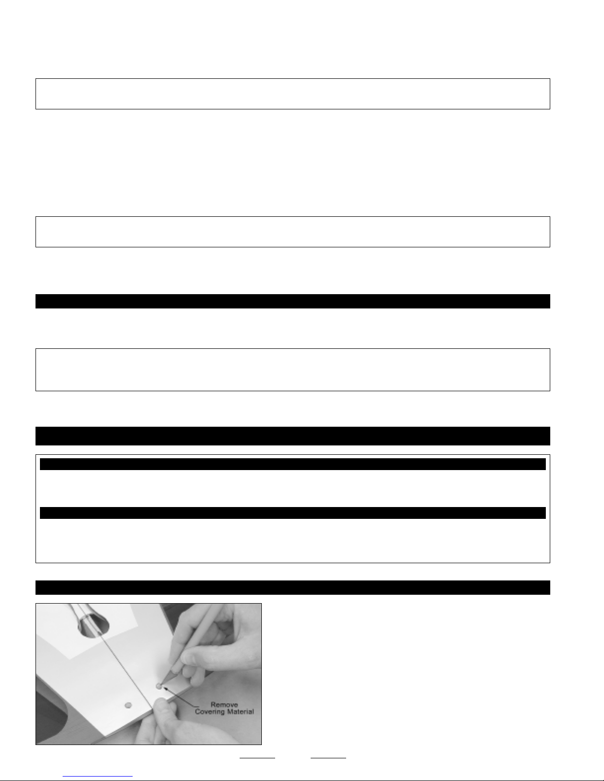
❑ Using a modeling knife, cut away and remove the covering material
from over the aileron servo lead exit hole in the top of the wing panel.
The hole is located on the edge of the root rib, 4-3/4" in front of the
trailing edge.
7
Continued On Next Page
☛☛
☛
☛☛

❑ Using a modeling knife, cut away and remove the covering material
from over the aileron servo mounting hole in the bottom of the wing
panel. The hole is located 13-1/2" out from the root rib and 3-1/4" in
front of the trailing edge.
❑ Tie the end of the length of preinstalled string in the servo mounting
hole to the servo extension plug and use it to pull the servo extension
lead through the wing panel.
Tie the end of the string to the servo extension plug at the servo mounting hole, then pull the string from the other end to guide
☞
the servo extension lead out through the top of the wing panel.
❑ Set the servo into place, making sure that the servo output shaft is
toward the leading edge of the wing panel.
❑ Install the aileron servo, making sure to drill 1/16" diameter pilot holes
for the mounting screws.
❑ Repeat the previous procedures to install the aileron servo into the second wing panel.
STEP 2: ALIGNING THE WING PANELS
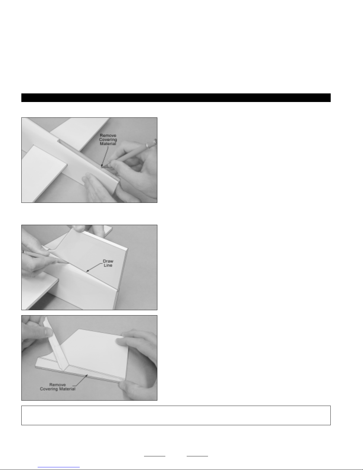
❑ Using a modeling knife, cut away and remove the excess covering
material that overlaps onto the root ribs of each wing panel, leaving
about 1/16" overlapped so it does not pull away.
✦✦
✦IMPORTANT
✦✦
from the root ribs as possible. Do not omit this procedure or the wing center-section joint may fail during flight.
✦✦
✦ It's very important to the integrity of the wing center-section joint that you remove as much covering material
✦✦
8
Continued On Next Page
☛☛
☛
☛☛

❑ Use a ruler and a pencil to locate and draw a vertical centerline on
one side of the plywood wing joiner.
✦✦
✦IMPORTANT
✦✦
or bottom.
❑ Test-fit the wing joiner into each wing panel. It should slide easily
into each wing panel up to the centerline you drew.
✦✦
✦IMPORTANT
✦✦
tightly into the wing panels. It should actually be slightly loose. This
will ensure that when you glue the wing joiner into place that epoxy
can get into the joints between the wing joiner and the joiner box.
This will ensure the strongest joint possible.
If the wing joiner does not fit properly, use 220 grit sandpaper
☞
with a sanding block to lightly sand the wing joiner, until you are satisfied
with the fit.
✦✦
✦ The plywood wing joiner is straight. There is no top
✦✦
✦✦
✦ When the wing joiner is installed, it should not fit
✦✦
❑ Carefully slide both wing panels together with the wing joiner
temporarily installed (without using glue).
❑ While holding the two wing panels together firmly, make sure that the wing panels are lined up at both the leading and trailing
edges, then look carefully at the center-section joint: the wing panels should fit together tightly with few or no gaps in the joint.
✦✦
✦IMPORTANT
✦✦
sanding block to lightly sand the edges and tips of the wing joiner, until you are satisfied with the fit. Remember, when the wing
panels are pushed together, there should be few or no gaps in the center-section joint.
STEP 3: JOINING THE WING PANELS
✦✦
✦ If the wing panels do not fit together properly, remove the wing joiner and use 220 grit sandpaper with a
✦✦
❑ When satisfied with the fit and alignment, pull the wing panels apart
and remove the wing joiner.
❑ Apply a strip of masking tape to the top and bottom edges of the root
rib on each wing panel.
The masking tape will prevent excess epoxy from getting onto the
☞
wing panels when you join them.
9
Continued On Next Page
☛☛
☛
☛☛
❑ Mix a generous amount of 30 minute epoxy. Working with only one wing panel for now, apply a thin layer of epoxy inside the wing
joiner box and to only half of the wing joiner. Make sure to cover the top and bottom, as well as the sides, and use enough epoxy to
fill any gaps.
✦✦
✦WARNING
✦✦
minute epoxy. It is not strong enough. If you use 5 minute epoxy, the wing will fail during flight.
❑ Slide the wing joiner into the wing panel up to the centerline mark. Quickly remove any excess epoxy, using a paper towel and
rubbing alcohol, and allow the epoxy to set up before proceeding.
❑ After the epoxy has set up, test-fit both wing panels together again to double-check that they still fit together properly. Check the
leading and trailing edges, too. It's important that they be even with each other.
❑ Mix a generous amount of 30 minute epoxy and apply a thin layer to the exposed half of the wing joiner, the inside of the wing
joiner box in the second wing panel, and the entire surface of BOTH root ribs. Make sure to use enough epoxy to fill any gaps.
✦✦
✦IMPORTANT
✦✦
of epoxy to both root ribs and the wing joiner. Not using enough epoxy can result in wing failure during flight.
❑ Slide the two wing panels together and realign them. Quickly wipe away any excess epoxy, using a paper towel and rubbing
alcohol, and use pieces of masking tape to hold the two wing panels aligned until the epoxy fully cures.
STEP 4: CHECKING THE WING CENTER-SECTION JOINT
❑ Once the epoxy has fully cured, remove the masking tape and double-check the center-section joint. If any gaps are present,
mix a small quantity of 30 minute epoxy and carefully fill any remaining gaps.
✦✦
✦IMPORTANT
✦✦
that appear after the epoxy has cured. To make the wing center-section joint as strong as possible, it's important to fill any gaps,
using 30 minute epoxy.
✦✦
✦ Use only 30 or 45 minute epoxy to install the wing joiner and to join the wing panels together. Do not use 5
✦✦
✦✦
✦ It is of the utmost importance to the integrity of the wing center-section joint that you apply a generous amount
✦✦
✦✦
✦ Do not omit this procedure. The wing panels should fit together tightly, but it's possible to have some small gaps
✦✦
SECTION 6: WING MOUNTING
YOU'LL NEED THE FOLLOWING PARTS FROM THE KIT:
❑ (1) Fuselage
❑ (2) Plywood Wing-Screw Doubler (W35)
YOU'LL NEED THE FOLLOWING TOOLS AND SUPPLIES:
❑ Kwik Bond Thick C/A
❑ # 2 Phillips Head Screwdriver
❑ Excel Modeling Knife
STEP 1: INSTALLING THE WING-SCREW DOUBLER
❑ (2) M4 x 40mm Machine Screws
❑ (2) M4 Flat Washers
❑ Ernst Airplane Stand
❑ Ruler
❑ Pencil
❑ Using a modeling knife, cut away and remove the covering material
from over the top and bottom of the two predrilled wing-screw mounting
holes in the trailing edge of the wing. The holes are located 5/8" in front
of the trailing edge and 3/4" out from the center-section joint.
10
Continued On Next Page
☛☛
☛
☛☛

❑ Place the wing-screw doubler onto the bottom of the wing and align
the predrilled holes in the wing-screw doubler with the predrilled holes
in the wing.
❑ While holding the wing-screw doubler in place, trace an outline around
it, using a pencil.
The back edge of the wing-screw doubler should be about
☞
1/16"-3/32" in front of the trailing edge of the wing.
❑ Using a modeling knife, cut away and remove the covering material
from inside the outline you drew.
✦✦
✦IMPORTANT
✦✦
Always remove the covering material first to ensure a strong glue joint.
❑ Using a generous amount of thick C/A, glue the wing-screw doubler to the wing. Allow the C/A to fully cure before proceeding.
STEP 2: MOUNTING THE WING
❑ Place the wing into the wing saddle, push it forward completely, then
push the trailing edge down into place.
Two holes have been predrilled into the forward bulkhead to accept
☞
the wing hold-down dowels in the leading edge of the wing.
✦✦
✦ Never glue anything directly to covering material.
✦✦
❑ Turn the fuselage over and check the fit between the wing and the wing saddle. There shouldn't be any gaps between the two.
If there are any small gaps, we suggest that you apply a strip of foam wing saddle tape (not included) to the wing saddle to seal
the gaps.
Foam tape will prevent fuel from getting inside the fuselage during flight.
☞
❑ Align the holes in the wing with the preinstalled blind nuts in the wing
mounting block inside the fuselage.
❑ Secure the wing into place, using two M4 x 40mm machine screws
and two M4 flat washers.
Don't overtighten the screws. You don't want to crush the wing.
☞
11

SECTION 7: BELLY PAN INSTALLATION
YOU'LL NEED THE FOLLOWING PARTS FROM THE KIT:
❑ (1) Belly Pan
YOU'LL NEED THE FOLLOWING TOOLS AND SUPPLIES:
❑ Wilhold Silicon Sealant
❑ Excel Modeling Knife
❑ Ernst Airplane Stand
❑ Pencil
STEP 1: ALIGNING THE BELLY PAN
❑ 220 Grit Sandpaper w/Sanding Block
❑ Masking Tape
❑ Paper Towels
❑ Waxed Paper
❑ Using a modeling knife, cut away and remove the covering material
from over the two precut wing-screw access holes in the bottom of the
belly pan.
❑ Using a modeling knife, carefully cut out the back of the belly pan,
as shown.
✦✦
✦IMPORTANT
✦✦
to retrieve the wing screws and washers should they fall loose into
the belly pan after it's glued to the wing.
❑ With the wing installed onto the fuselage, position the belly pan onto
the wing. When lined up properly, the sides and bottom of the belly
pan should be even with the sides and bottom of the fuselage, and
there should be few or no gaps between the base of the belly pan and
the wing.
Some small gaps between the belly pan and the wing are normal.
☞
They will be filled with silicon when the belly pan is glued in place.
✦✦
✦IMPORTANT
✦✦
and the front and back of the belly pan.
If there are any large gaps between the base of the belly pan and the wing, use 220 grit sandpaper to sand away some material
from the base of the belly pan. Remove small amounts of material at a time and recheck the fit often until you are satisfied with
the fit.
✦✦
✦ So that the wing can be installed and removed, there should be about a 1/16" wide space between the fuselage
✦✦
✦✦
✦ Cutting out the back of the belly pan will allow you
✦✦
12
Continued On Next Page
☛☛
☛
☛☛

STEP 2: INSTALLING THE BELLY PAN
❑ Remove the wing, lay a long piece of waxed paper over the wing
saddle, then reinstall the wing, making sure that the ends of the waxed
paper are covering the joints between the fuselage and the leading and
trailing edges of the wing.
✦✦
✦IMPORTANT
✦✦
when you glue the belly pan to the wing. The waxed paper will
ensure that you don't accidentally glue the wing to the fuselage when
you glue the belly pan into place.
❑ Apply a generous bead of silicon sealant to the base of the belly
pan, making sure that you cover all of the gluing surfaces. This includes
not only the sides of the belly pan, but the front and back, too.
Make sure to use enough silicon sealant to fill any small gaps or
☞
irregularities in the glue joint.
❑ Set the belly pan back into place and realign it. When satisfied with the alignment, push the belly pan down firmly and remove
any excess silicon sealant, using a paper towel and water. Hold the belly pan securely in place, using pieces of masking tape, until
the silicon sealant completely cures.
✦✦
✦IMPORTANT
✦✦
time. You must allow sufficient time for the silicon sealant to dry.
✦✦
✦ It will take the silicon sealant about 24 hours to fully cure. We suggest not moving the assembly during this
✦✦
✦✦
✦ It's important to use waxed paper or plastic wrap
✦✦
❑ After the silicon sealant has fully cured, look carefully at the glue joint between the belly pan and the wing. If there are any gaps
in the glue joint, carefully fill them using extra silicon sealant, making sure to remove any excess before it cures, using a paper towel
and water. This will ensure the strongest possible bond.
SECTION 8: STABILIZER INSTALLATION
YOU'LL NEED THE FOLLOWING PARTS FROM THE KIT:
❑ (1) Horizontal Stabilizer w/Elevator Halves
YOU'LL NEED THE FOLLOWING TOOLS AND SUPPLIES:
❑ Kwik Bond 30 Minute Epoxy
❑ Excel Modeling Knife
❑ Ernst Airplane Stand
❑ Ruler
❑ Pencil
❑ Dubro T-Pins
❑ Builder's Triangle
STEP 1: ALIGNING THE HORIZONTAL STABILIZER
❑ Remove the elevator halves and hinges from the horizontal stabilizer and set them aside for now.
❑ (1) Vertical Stabilizer w/Rudder
❑ 220 Grit Sandpaper w/Sanding Block
❑ Masking Tape
❑ Paper Towels
❑ Rubbing Alcohol
❑ NHP Epoxy Mixing Sticks
❑ NHP Epoxy Mixing Cups
13
Continued On Next Page
☛☛
☛
☛☛

❑ Using a modeling knife, cut away and remove the covering material
from over the horizontal stabilizer mounting slot in each side of the
fuselage.
The slot is located 7" in front of the back edge of the fuselage and
☞
is 4" long and 5/16" wide.
❑ Slide the horizontal stabilizer into the mounting slot and center it by
carefully measuring out from each side of the fuselage to each end of
the stabilizer (at the trailing edge only for now). When the stabilizer is
centered, both measurements will be equal.
✦✦
✦IMPORTANT
✦✦
✦✦
✦IMPORTANT
✦✦
aligned. The trailing edge should not be allowed to move from side to side.
✦✦
✦ Make sure that the top of the stabilizer (the white side) is facing up when you slide it into place.
✦✦
❑ When you're satisfied that the stabilizer is centered at the trailing
edge, draw a mark on each side of the stabilizer (at the trailing edge)
where it meets the fuselage sides.
❑ With the marks on the stabilizer lined up with the fuselage sides, hold
only the trailing edge of the stabilizer in position, using a T-Pin.
✦✦
✦ The front of the stabilizer should be able to pivot from side to side and the back should stay firmly in place and
✦✦
❑ With the wing mounted to the fuselage, use a ruler to measure the
distance between the tips of the stabilizer and the tips of the wing. Pivot
the front of the stabilizer until both of these measurements are equal.
B=B-1
When both of these measurements are equal, you're assured
☞
that the stabilizer is square to the wing.
14
Continued On Next Page
☛☛
☛
☛☛

❑ When you're satisfied that the stabilizer is square to the wing, use a pencil to draw a couple of marks on each side of the front
of the stabilizer where it and the fuselage sides meet, then use a couple of T-Pins to hold the stabilizer firmly in place and aligned.
❑ With the stabilizer held firmly in place, look from the front of the
airplane at both the wing and the stabilizer. When aligned properly, the
stabilizer should be parallel to the wing.
C=C-1
If the stabilizer is not parallel to the wing, remove it and use 220 grit sandpaper with a sanding block to sand down the higher
☞
side of the stabilizer mounting slot, then reinstall the stabilizer and check the alignment once more. Repeat this procedure until
you are satisfied with the alignment.
STEP 2: MOUNTING THE HORIZONTAL STABILIZER
❑ When satisfied with the alignment, use a pencil to draw a line on
each side of the stabilizer where it meets the fuselage sides. Do this on
both the top and the bottom.
✦✦
✦IMPORTANT
✦✦
prevent the epoxy from spreading over the entire length of one half of the stabilizer when you slide it into place.
✦✦
✦ Because the stabilizer has to slide into place through the fuselage, apply epoxy only to the stabilizer. This will
✦✦
❑ Remove the stabilizer from the fuselage and use a modeling knife to
carefully cut away and remove the covering material from between the
lines you drew. Do this on both the top and the bottom.
✦✦
✦WARNING
✦✦
with only enough pressure to cut through only the covering itself.
Cutting down into the balsa structure could weaken the stabilizer and
cause it to fail during flight.
❑ To make it less messy during installation, apply masking tape to the
fuselage around the side of the mounting slot that the stabilizer will slide
into. Apply masking tape to the top and bottom of the corresponding
side of the stabilizer, too.
❑ Partially slide the stabilizer into the mounting slot.
15
✦✦
✦ When cutting through the covering to remove it, cut
✦✦
Continued On Next Page
☛☛
☛
☛☛
❑ Mix and apply a generous amount of 30 minute epoxy to ONLY the top and bottom gluing surfaces of the stabilizer.
❑ Push the stabilizer into place and realign it, double-checking all of your measurements once more before the epoxy sets up.
Quickly remove any excess epoxy and use T-Pins to hold the stabilizer in place and aligned until the epoxy has fully cured.
❑ After the epoxy has fully cured, remove the T-Pins and masking tape and look closely at the glue joint. If there are any gaps
between the stabilizer and the fuselage, fill them using 30 minute epoxy for added strength. Again, before the epoxy sets up,
remove any excess epoxy, using a paper towel and rubbing alcohol.
STEP 3: ALIGNING AND MOUNTING THE VERTICAL STABILIZER
❑ Remove the rudder and hinges from the vertical stabilizer and set them aside for now.
❑ Using a modeling knife, cut away and remove the covering material
from over the vertical stabilizer mounting slot in the top of the fuselage.
The slot is 6" long and 5/16" wide.
❑ Push the vertical stabilizer down into the mounting slot. To align it properly, the trailing edge of the stabilizer should be even with
the back edge of the fuselage and the stabilizer should be pushed down firmly.
❑ While holding the vertical stabilizer firmly in place, use a pencil to
draw a line on each side of the vertical stabilizer where it meets the top
of the fuselage.
❑ Remove the vertical stabilizer and use a modeling knife to carefully
cut away and remove the covering material from below the lines you
drew. Remove the covering material from the base of the vertical
stabilizer, too.
✦✦
✦WARNING
✦✦
itself. Cutting down into the balsa structure could weaken the stabilizer and cause it to fail during flight.
❑ Mix and apply a generous amount of 30 minute epoxy to the gluing surfaces of both the vertical stabilizer and to the vertical
stabilizer mounting slot in the top of the fuselage.
✦✦
✦ When cutting through the covering to remove it, cut with only enough pressure to cut through only the covering
✦✦
16
Continued On Next Page
☛☛
☛
☛☛

❑ Push the vertical stabilizer down into place and realign it, double-
checking all of your measurements once more before the epoxy sets
up. Quickly remove the excess epoxy, and use pieces of masking tape
to hold the vertical stabilizer in place, until the epoxy has fully cured.
✦✦
✦IMPORTANT
✦✦
horizontal stabilizer.
✦✦
✦ Before the epoxy sets up, use a builder's triangle to make sure that the vertical stabilizer is perpendicular to the
✦✦
SECTION 9: CONTROL SURFACE HINGING
YOU'LL NEED THE FOLLOWING PARTS FROM THE KIT:
❑ (17) C/A-Style Hinges
YOU'LL NEED THE FOLLOWING TOOLS AND SUPPLIES:
❑ Kwik Bond Thin C/A
❑ Kwik Bond C/A Debonder
❑ Excel Modeling Knife
❑ Ernst Airplane Stand
STEP 1: HINGING THE AILERONS
✦✦
✦Important Information About the C/A-Style Hinges Included with Your Magic Formula 3D ARF
✦✦
The hinges are NOT glued into place at the factory, they are simply slid into place dry for shipping purposes. You must glue them
into place.
The Magic Formula 3D ARF uses C/A-style hinges to hinge the control surfaces. These hinges are designed to be glued into
place using thin C/A. Do not glue these hinges into place using any other type of glue, such as thick C/A or epoxy. Use of any
adhesive other than thin C/A could result in failure of the hinges during flight.
❑ Dubro T-Pins
❑ Masking Tape
❑ Paper Towels
✦✦
✦
✦✦
For flutter-free control surfaces and crisp control response, it is imperative that the hinges be glued in properly. This is achieved
by having a tight hinge gap (no more than 1/32" wide) and using plenty of thin C/A glue. Poor hinge installation can lead to control
surface flutter which can result in a catastrophic failure of the airframe.
If the hinge(s) can't be pushed in far enough to achieve the proper hinge gap, you'll need to use a modeling knife with a # 11 blade
to cut the hinge slot(s) deeper.
❑ Push two T-Pins through the center of four C/A-style aileron hinges,
as shown.
The T-Pins will keep the hinges centered and square to the
☞
hinge line while you are hinging the aileron.
17
Continued On Next Page
☛☛
☛
☛☛

❑ Slide one hinge into each hinge slot in one aileron, making sure that
you push each hinge in up to the T-Pins. Don't glue the hinges into the
aileron yet, though.
✦✦
✦IMPORTANT
✦✦
❑ Push the aileron and its hinges into the hinge slots in the trailing edge of the corresponding side of the wing. Remove the T-Pins
and push the aileron into its final position. The aileron should be pushed firmly up against the trailing edge, so that there is a minimal
hinge gap (no more than 1/32" wide), and the outer end of the aileron should not rub against the wing panel. There should be about
a 1/16" - 3/32" wide gap between the two.
❑ Allow the C/A to dry for about 15 minutes, then pivot the aileron up and down several times to free up the hinges.
PRO TIP
the hinges. The hinges should hold securely. If one or more hinges feels loose, apply more C/A to the hinge(s) and allow it to
completely cure.
✦✦
✦ Notice that the ailerons are hinged along the top. This is normal and by design.
✦✦
❑ While holding the aileron tight against the trailing edge of the wing,
pivot the aileron down about 45º and apply 5-6 drops of thin C/A to the
exposed area of each hinge. Turn the wing over and repeat for the
other side of the hinges.
Remove any C/A that may run down the hinge line, using C/A
☞
Debonder.
After the C/A has fully cured, gently grasp the aileron and wing and pull on the aileron like you are trying to pull out
❑ Repeat the previous procedures to hinge the other aileron to the wing, making sure to check the integrity of the hinges
after the C/A fully cures. The last thing you want is for a hinge to come loose during flight.
STEP 2: HINGING THE ELEVATOR HALVES
✦✦
✦IMPORTANT
✦✦
C/A to the hinge(s) if necessary.
✦✦
✦ After allowing the C/A to fully cure, pull on the elevator halves to check the integrity of the hinges. Apply more
✦✦
❑ Hinge the elevator halves, using the same techniques that you used
to hinge the ailerons. Each elevator half is hinged using three hinges.
When hinging the elevator halves, there should be a 1/16" wide gap
between the ends of the stabilizer and the elevator counterbalances.
There should also not be more than a 1/32" wide hinge gap.
18
Continued On Next Page
☛☛
☛
☛☛

STEP 3: HINGING THE RUDDER
❑ Hinge the rudder, using the same techniques that you used to hinge
the ailerons and the elevator halves. The rudder is hinged using three
hinges. When hinging the rudder, there should be a 1/16" wide gap
between the end of the stabilizer and the rudder counterbalance. There
should also not be more than a 1/32" wide hinge gap.
✦✦
✦IMPORTANT
✦✦
hinge(s) if necessary.
✦✦
✦ After allowing the C/A to fully cure, pull on the rudder to check the integrity of the hinges. Apply more C/A to the
✦✦
SECTION 10: TAIL SKID INSTALLATION
YOU'LL NEED THE FOLLOWING PARTS FROM THE KIT:
❑ (1) Prebent Tail Skid
❑ (2) Nylon Mounting Straps
YOU'LL NEED THE FOLLOWING TOOLS AND SUPPLIES:
❑ # 1 Phillips Head Screwdriver
❑ Excel Modeling Knife
❑ Electric Drill
❑ 1/16" Drill Bit
STEP 1: INSTALLING THE TAIL SKID
❑ (4) M2 x 10mm Wood Screws
❑ Ernst Airplane Stand
❑ Ruler
❑ Pencil
❑ Using a modeling knife, cut away and remove the covering material
from over the tail skid mounting slot in the bottom of the fuselage. The
slot is 2-1/2" long and 1/8" wide.
❑ Insert the 90º bend in the tail skid into the predrilled hole in the tail
skid mounting slot, then firmly push the tail skid down into the slot.
❑ Place the two nylon mounting straps equally spaced apart over the
tail skid and use a pencil to mark the locations of the four mounting
holes onto the bottom of the fuselage.
19
Continued On Next Page
☛☛
☛
☛☛

❑ Remove the nylon mounting straps and drill four 1/16" diameter pilot
holes into the fuselage at the marks you drew.
❑ Install the two nylon mounting straps, using four M2 x 10mm wood
screws, to secure the tail skid into place.
SECTION 11: LANDING GEAR INSTALLATION
YOU'LL NEED THE FOLLOWING PARTS FROM THE KIT:
❑ (1) Aluminum Landing Gear Bracket
❑ (2) Molded Wheel Pants
❑ (2) Main Gear Wheels
❑ (2) M4 x 35mm Threaded Axles
❑ (3) M4 x 16mm Machine Screws
YOU'LL NEED THE FOLLOWING TOOLS AND SUPPLIES:
❑ Pacer Z-42 Blue Threadlocker
❑ # 2 Phillips Head Screwdriver
❑ Adjustable Wrench (2)
❑ Excel Modeling Knife
❑ Electric Drill
❑ (4) M4 Lock Nuts
❑ (2) Nylon Spacers
❑ (2) M2 x 10mm Flange-Head Wood Screws
❑ (13) M4 Flat Washers
❑ 5/32" Drill Bit
❑ Ernst Airplane Stand
❑ Ruler
❑ Pencil
❑ 220 Grit Sandpaper w/Sanding Block
STEP 1: INSTALLING THE LANDING GEAR BRACKET
❑ Using a modeling knife, cut away and remove the covering material
from over the three predrilled landing gear mounting holes in the bottom
of the fuselage. The location of the holes should be visible underneath
the covering material.
❑ Install the aluminum landing gear bracket to the bottom of the
fuselage, using three M4 x 16mm machine screws and three M4 flat
washers.
Blind nuts have been preinstalled into the landing gear mounting
☞
block to thread the screws into.
✦✦
✦IMPORTANT
✦✦
machine screws so that they don't come loose during flight.
✦✦
✦ We suggest applying Blue Threadlocker to the
✦✦
20
Continued On Next Page
☛☛
☛
☛☛

STEP 2: INSTALLING THE WHEELS AND WHEEL PANTS
❑ Using a modeling knife, carefully cut away the material from over the
wheel opening in one wheel pant.
❑ Use 220 grit sandpaper to sand the edges of the wheel pant opening smooth.
❑ Drill a 5/32" diameter hole into one side of the wheel pant, using the
molded dimple as your guide.
❑ Using a modeling knife, carefully cut a slot from the hole you drilled
down to the bottom of the wheel pant, as shown.
This slot will allow you to slide the wheel pant over the threaded axle.
☞
❑ Slide one main gear wheel onto one M4 x 35mm threaded axle, flat side first.
❑ Slide one nylon spacer up against the wheel, then slide three M4 flat
washers up against the nylon spacer.
❑ Thread one M4 lock nut onto the threaded axle and tighten it firmly.
✦✦
✦IMPORTANT
✦✦
wheel is tight, remove one flat washer and retighten the lock nut. It may be necessary to remove 1 or 2 flat washers to achieve
a perfect fit.
✦✦
✦ When you tighten the lock nut, the wheel should spin freely and have only slight side to side play. If the
✦✦
21
Continued On Next Page
☛☛
☛
☛☛

❑ Slide one M4 flat washer up against the hex nut, then slide the wheel
and threaded axle assembly into the slot in the wheel pant, making sure
that the flat washer is on the inside of the wheel pant .
❑ Slide the end of the threaded axle through the predrilled hole in the main gear bracket.
❑ Secure the threaded axle to the main gear bracket, using one M4 flat
washer and one M4 lock nut. Tighten the outer lock nut firmly while
securely holding the inner lock nut in place.
✦✦
✦IMPORTANT
✦✦
✦✦
✦ Tighten the lock nut firmly so that the wheel pant cannot rotate under pressure.
✦✦
❑ While holding the wheel pant aligned (the bottom of the wheel pant
should be parallel to the bottom edge of the landing gear bracket), use
the tip of your modeling knife to make a small pilot hole in the wheel
pant, using the predrilled hole in the landing gear bracket as a guide.
❑ Install and tighten one M2 x 10mm flange-head wood screw to lock
the wheel pant into place and keep it from rotating.
✦✦
✦IMPORTANT
✦✦
the plastic.
✦✦
✦ Don't overtighten the wood screw or you might strip
✦✦
❑ Repeat the previous procedures to install the second wheel and wheel pant assembly.
✦✦
✦IMPORTANT
✦✦
lined up with each other when viewed from the side.
✦✦
✦ Before installing the wood screw in the second wheel pant assembly, double-check that both wheel pants are
✦✦
22

SECTION 12: ENGINE INSTALLATION
YOU'LL NEED THE FOLLOWING PARTS FROM THE KIT:
❑ (2) Engine Mounting Beams
❑ (4) M4 x 20mm Socket-Cap Screws
❑ (4) M4 x 25mm Socket-Cap Screws
YOU'LL NEED THE FOLLOWING TOOLS AND SUPPLIES:
❑ Pacer Z-42 Blue Threadlocker
❑ 3mm Hex Wrench
❑ Adjustable Wrench
❑ Electric Drill
STEP 1: INSTALLING THE ENGINE MOUNTING BEAMS
❑ (4) M4 Lock Nuts
❑ (12) M4 Flat Washers
❑ (1) Spinner Assembly w/Backplate & Screws
❑ 3/32" & 5/32" Drill Bits
❑ Ruler
❑ Pencil
✦✦
✦IMPORTANT
✦✦
engine, the installation procedures are the same. The Magnum XL .70RFS engine is shown.
The mounting holes in the firewall are prespaced to fit the Magnum XL .61ARNV two-stroke engine and the Magnum XL .70RFS
four-stroke engine. If you are using a different size engine, such as the XLS .52A two-stroke engine or the XL .61RFS four-stroke
engine, you will have to modify the spacing of the mounting holes. This can be done by removing the blind nuts and gluing pieces
of hardwood dowel into the existing holes. You can then redrill the holes to fit your engine's width and reinstall the blind nuts.
Note that the engine is mounted inverted to fit properly within the cowling and to allow the muffler to exit the side of the fuselage.
STEP 2: ALIGNING AND INSTALLING THE ENGINE
✦✦
✦ The following procedures outline the installation of a four-stroke engine. If you are installing a two-stroke
✦✦
❑ Install the two engine mounting beams onto the firewall, using four
M4 x 20mm socket-cap screws and four M4 flat washers. Tighten the
screws firmly to hold the engine mounting beams securely in place.
Blind nuts have been preinstalled into the back of the firewall to
☞
thread the screws into. We suggest applying Blue Threadlocker to the
screws to prevent them from loosening during flight.
✦✦
✦IMPORTANT
✦✦
the firewall. The distance from the firewall to the back of the spinner backplate should be 4-1/2". This measurement is the same
whether you're installing a two-stroke engine or a four-stroke engine. This measurement will allow a 1/16" wide gap between the
front of the cowling and the spinner backplate, and allow the cowling to overlap the fuselage approximately 1/4".
✦✦
✦ So that the cowling will line up properly when it's installed later, the engine must be spaced out correctly from
✦✦
❑ Remove the muffler assembly, high speed needle valve and choke
lever (if applicable) from your engine and set them aside.
❑ Install the spinner backplate onto your engine's crankshaft, using
the propeller washer and nut included with your engine.
Depending on the diameter of your engine's crankshaft, you may
☞
need to enlarge the diameter of the hole in the spinner backplate to fit.
Use a drill bit or a propeller reamer to do this.
23
Continued On Next Page
☛☛
☛
☛☛

❑ With the fuselage upside down, set the engine onto the engine
mounting beams.
❑ Using a ruler, measure the distance from the firewall to the back of
the spinner backplate. Adjust the depth of the engine so that the
measurement is 4-1/2".
❑ Using a pencil, carefully mark the locations of the engine mounting holes onto the engine mounting beams.
❑ Remove the engine and drill 3/32" diameter pilot holes through the
engine mounting beams at the marks you drew.
✦✦
✦IMPORTANT
✦✦
and not at an angle.
❑ Carefully enlarge the 3/32" diameter pilot holes, using a 5/32"
diameter drill bit.
❑ Install the engine using four M4 x 25mm socket-cap screws, eight
M4 flat washers and four M4 lock nuts.
Tighten the screws and lock nuts firmly to hold the engine securely
☞
into place.
✦✦
✦ Be careful that you drill the holes straight down
✦✦
SECTION 13: THROTTLE CONTROL SYSTEM INSTALLATION
YOU'LL NEED THE FOLLOWING PARTS FROM THE KIT:
❑ (1) 13-1/4" Plain Wire w/Z-Bend
YOU'LL NEED THE FOLLOWING TOOLS AND SUPPLIES:
❑ Kwik Bond Thin C/A
❑ # 1 & # 2 Phillips Head Screwdrivers
❑ Wire Cutters
❑ Needle Nose Pliers
STEP 1: INSTALLING THE THROTTLE SERVO
❑ Install the rubber grommets and brass collets onto your throttle servo, making sure to install the collets with the flanges toward
the bottom of the servo.
❑ (1) Adjustable Pushrod Connector w/Machine Screw & Nut
❑ Electric Drill
❑ 1/16" & 5/64" Drill Bits
❑ Ernst Airplane Stand
❑ Ruler
24
Continued On Next Page
☛☛
☛
☛☛

❑ Install the throttle servo into the forward hole in the plywood servo
tray, making sure to drill 1/16" diameter pilot holes for the mounting screws.
✦✦
✦IMPORTANT
✦✦
of the fuselage, as shown.
STEP 2: INSTALLING THE THROTTLE PUSHROD WIRE
✦✦
✦IMPORTANT
✦✦
arm can be more tricky than if we were using a two-stroke engine. This is because the carburetor on most four-stroke engines is
on the back of the engine, close to the firewall. To make connecting the throttle pushrod wire easier, we made a 180º bend in the
end of the throttle pushrod wire. This allows the Z-Bend to be connected to the throttle arm without causing the pushrod wire to
bind. This also ensures that the throttle pushrod wire will not interfere with the installation of the fuel tank assembly. Installing the
throttle pushrod wire will be the same if you are using a two-stroke engine. The only difference will be that you will only need to
make a slight bend in the pushrod wire to line up with your engine's throttle arm.
✦✦
✦IMPORTANT
✦✦
✦✦
✦ Since we are using a four-stroke engine in our model, attaching the throttle pushrod wire to the engine's throttle
✦✦
✦✦
✦ If you're using a two-stroke engine, don't make a 180º bend in the pushrod wire as shown in the next procedure.
✦✦
✦✦
✦ The servo output shaft should be toward the front
✦✦
❑ Using a pair of pliers, carefully make a shallow 180º bend in the
pushrod wire.
❑ Remove the throttle arm from your engine and install the Z-Bend in the pushrod wire into the outermost hole in the throttle arm.
You may need to enlarge the hole in your engine's throttle arm, using a 5/64" diameter drill bit, to accommodate the pushrod wire.
☞
❑ Slide the plain end of the pushrod wire into the predrilled hole in
the firewall, then reinstall the throttle arm onto your engine.
❑ Double-check that the pushrod wire does not bind. The carburetor
barrel should open and close smoothly and completely. You may need
to make a couple of bends in the pushrod wire, so that the pushrod
assembly will operate smoothly.
If you're using a four-stroke engine, you will need to make a bend in
☞
the pushrod wire where it exits the firewall, so that the pushrod wire will
line up with your engine's throttle arm.
STEP 3: INSTALLING THE ADJUSTABLE PUSHROD CONNECTOR
❑ Using a modeling knife, cut away all but one arm from a "4-point" servo horn.
25
Continued On Next Page
☛☛
☛
☛☛

❑ Enlarge the hole in the servo arm that is 11/16" out from the center of
the servo arm, using a 5/64" diameter drill bit.
❑ Install the adjustable pushrod connector into the enlarged hole in
the servo arm.
✦✦
✦IMPORTANT
✦✦
the nut completely. You don't want the pushrod connector loose, but
you do want it to be able to rotate without binding.
PRO TIP
before proceeding.
❑ Connect your radio system and plug the throttle servo into the receiver. Check to ensure that the throttle servo output shaft
is rotating in the correct direction. When the throttle control stick is moved forward, from the idle to the full throttle position, the
servo output shaft should rotate in the correct direction to open your engine's carburetor. If it doesn't, flip the servo reversing
switch on your transmitter.
For the Magnum XL .70RFS, the servo output shaft should rotate clockwise to open the carburetor.
☞
❑ Position the throttle control stick and the throttle trim lever on your transmitter to their lowest positions.
❑ Slide the adjustable pushrod connector/servo horn assembly over the plain end of the throttle pushrod wire.
✦✦
✦IMPORTANT
✦✦
shallow notch in the side of the forward bulkhead for the pushrod wire to ride in. You will also need to make a shallow bend in the
pushrod wire, so that it lines up with the adjustable pushrod connector. See the photo below for more detail.
To prevent the knurled nut from loosening during flight, apply a drop of thin C/A to it. Allow the C/A to fully cure
✦✦
✦ So that the fuel tank does not interfere with the pushrod wire when it's installed later, you will need to cut a
✦✦
✦✦
✦ When threading on the knurled nut, don't tighten
✦✦
❑ Operate the throttle several times to ensure that the pushrod wire does not bind and that the carburetor opens and closes
completely. You may need to adjust your transmitter EPA settings to achieve perfect settings. You may also need to fine tune the
bends in the pushrod wire so that it doesn't bind. This is especially true if you're using a four-stroke engine.
❑ After making sure that the carburetor is in the fully closed position,
angle the servo horn about 45º from center and attach it to the servo
output shaft.
❑ While holding the carburetor fully closed, install and tighten the
machine screw in the top of the adjustable pushrod connector.
❑ Use wire cutters to cut away and remove the excess pushrod wire,
then install and tighten the servo horn retaining screw to hold the servo
horn securely to the servo.
26

SECTION 14: FUEL TANK ASSEMBLY AND INSTALLATION
YOU'LL NEED THE FOLLOWING PARTS FROM THE KIT:
❑ (1) 320cc Fuel Tank
❑ (1) Large Diameter Metal Plate
❑ (1) Small Diameter Metal Plate
❑ (1) Neck-Reinforcement Ring
❑ (1) Rubber Stopper
YOU'LL NEED THE FOLLOWING TOOLS AND SUPPLIES:
❑ # 2 Phillips Head Screwdriver
❑ Excel Modeling Knife
❑ Scissors
STEP 1: ASSEMBLING THE RUBBER STOPPER
❑ (1) Fuel Pick-Up "Clunk"
❑ (1) M3 x 20mm Machine Screw
❑ (1) Silicone Fuel Tubing
❑ (3) Aluminum Tubing
❑ Ruler
❑ 220 Grit Sandpaper w/Sanding Block
✦✦
✦IMPORTANT
✦✦
❑ Using 220 grit sandpaper, carefully smooth and deburr each end of the two aluminum tubes. This will prevent the fuel tubing
from being accidentally cut when it is installed later.
❑ Push the two aluminum tubes through the rubber stopper. Slide the large diameter metal plate over the tubes at the front of the
rubber stopper and slide the small diameter metal plate over the tubes at the rear of the rubber stopper.
❑ Carefully bend the longer of the two aluminum tubes up at a 45º angle, being careful not to kink the tubing as you bend it.
✦✦
✦IMPORTANT
✦✦
rest inside the bubble in the top of the fuel tank.
✦✦
✦ Discard one of the two longer aluminum tubes. It will not be used for our style of fuel tank setup.
✦✦
❑ Using a ruler, measure the distance that the two aluminum tubes
protrude from the front of the stopper assembly. This distance should
be 3/8". If it is not, adjust the tubes by pushing them forward or
backward until you are satisfied with the alignment.
✦✦
✦ When the stopper assembly is installed in the fuel tank, the top of the vent tube (the tube you just bent) should
✦✦
❑ Secure one end of the silicone fuel tubing onto the end of the fuel pick-up "clunk."
❑ Push the M3 x 20mm machine screw through the front of the stopper assembly and partially thread it into the small diameter
metal backplate. Don't tighten the machine screw yet or you won't be able to install the stopper assembly into the fuel tank.
❑ Slide the silicone fuel tubing, with the fuel pick-up attached, onto the
end of the aluminum fuel pick-up tube (straight tube). While holding the
aluminum tube in place, adjust the length of the silicone tubing until the
end of the fuel pick-up is 4-1/2" back from the rear of the stopper
assembly.
27
Continued On Next Page
☛☛
☛
☛☛

STEP 2: INSTALLING THE STOPPER ASSEMBLY
❑ Push the metal neck-reinforcement ring over the neck of the molded
fuel tank opening, then carefully push the stopper assembly into the
molded hole in the front of the fuel tank and rotate the stopper assembly
until the aluminum vent tube rests inside the bubble in the top of the
fuel tank.
PRO TIP
inside of the fuel tank, making it easy to see the tubing inside.
❑ When satisfied with the alignment, tighten the machine screw until the rubber stopper expands and seals the fuel tank opening.
✦✦
✦IMPORTANT
✦✦
❑ With the rubber stopper assembly installed, double-check to make sure that the fuel pick-up can move freely inside the fuel tank.
Ideally, the fuel pick-up should be about 1/4" in front of the back of the fuel tank.
STEP 3: INSTALLING THE FUEL TANK
If you have trouble seeing the vent tube, hold the fuel tank assembly up to a bright light. This will illuminate the
✦✦
✦ Don't overtighten the machine screw or you might strip the threads in the small metal plate or split the fuel tank.
✦✦
❑ Cut two pieces of silicone fuel tubing (not included) to a length of 8"
and install them to the aluminum tubes at the front of the fuel tank.
PRO TIP
so you don't confuse them when it comes time to connect them to the
engine later on.
Mark the ends of the silicone tubing "vent" and "pick-up"
❑ Feed the ends of the fuel tubing through the predrilled hole in the firewall and slide the fuel tank into position, making sure that
the stopper assembly lines up with, and is firmly pushed into, the predrilled hole in the firewall.
✦✦
✦IMPORTANT
✦✦
❑ To align the fuel tank properly, the fuel tank should be pushed forward as far as possible and the fuel tank should be level from
front to back.
✦✦
✦ When you slide the fuel tank into position, make sure that the top of the fuel tank is toward the top of the fuselage.
✦✦
❑ Use your favorite method to secure the fuel tank into position. We
supported the top and bottom of the fuel tank with thick pieces of foam
rubber, then we glued a piece of scrap plywood to the inside of the
forward bulkhead, directly behind the fuel tank, to keep the fuel tank from
sliding backward.
Make sure that the fuel tank is held firmly in place. The last thing
☞
you want is for it to come loose during flight. It's important that it can't
slide backward during flight.
28

SECTION 15: ELEVATOR CONTROL SYSTEM INSTALLATION
YOU'LL NEED THE FOLLOWING PARTS FROM THE KIT:
❑ (2) 6-3/8" Threaded Wires w/90º Bends
❑ (2) Nylon Control Horns w/Backplates
❑ (2) Nylon Clevises
YOU'LL NEED THE FOLLOWING TOOLS AND SUPPLIES:
❑ Kwik Bond Thin C/A
❑ # 1 Phillips Head Screwdriver
❑ Wire Cutters
❑ Needle Nose Pliers
❑ Excel Modeling Knife
❑ Electric Drill
STEP 1: INSTALLING THE ELEVATOR SERVOS
❑ (2) Nylon 90º Snap-Keepers
❑ (4) M2 x 12mm Machine Screws
❑ 1/16" & 5/64" Drill Bits
❑ Ernst Airplane Stand
❑ Ruler
❑ Pencil
❑ Masking Tape
❑ Global Heat Gun
✦✦
✦IMPORTANT
✦✦
the fuselage. The servos are installed offset, so that no servo reverser is necessary.
✦✦
✦ The elevator control system uses two separate elevator servos and pushrod assemblies, one on each side of
✦✦
❑ Using a modeling knife, cut away and remove the covering material
from over the elevator servo mounting hole in each side of the fuselage.
Both holes are located 12" in front of the rudder hinge line. The
☞
hole on the right side of the fuselage is located 1" up from the bottom of
the fuselage and the hole on the left side of the fuselage is located
1-3/4" up from the bottom of the fuselage.
❑ Install the rubber grommets and brass collets onto both elevator
servos, making sure to install the collets with the flanges toward the
bottom of the servos.
❑ Plug one 12" servo extension onto each of the elevator servo leads.
❑ To prevent the plugs from pulling apart during assembly, or worse,
during flight, secure the plugs together, using a short piece of 3/8"
diameter heat-shrink tubing. Use a heat gun to shrink the tubing tight.
❑ Run the servo extension leads through the fuselage and into the radio
compartment, then install the elevator servos into the mounting holes,
making sure to drill 1/16" diameter pilot holes for the mounting screws.
✦✦
✦IMPORTANT
✦✦
of the fuselage, as shown.
29
✦✦
✦ Both servo output shafts should be toward the back
✦✦
Continued On Next Page
☛☛
☛
☛☛

STEP 2: INSTALLING THE CONTROL HORNS
✦✦
✦IMPORTANT
✦✦
sealing the control surface hinge gaps. It is strongly recommended that you do this, and it's much easier to do it now than later.
PRO TIP
the C/A to fully cure. The C/A will harden the surrounding balsa, making the mounting area stronger.
❑ Install the control horn and backplate, using two M2 x 12mm machine screws, being careful not to overtighten them.
❑ Using a pair of wire cutters, cut off the machine screws flush with the top of the control horn backplate.
❑ Repeat the previous procedures to align and install the second control horn assembly onto the other elevator half.
✦✦
✦ Before installing the control horns and pushrod assemblies, please refer to section 23 on page # 41 about
✦✦
❑ Position one nylon control horn onto one elevator half. When
aligned properly, the centerline of the control horn should be 3/8" out
from the inside edge of the elevator half (at the hinge line) and the clevis
attachment holes should be lined up over the hinge line. The base of
the control horn should be parallel to the hinge line, too, so that the
control horn will line up with the pushrod wire.
❑ When satisfied with the alignment, mark and drill 5/64" diameter
pilot holes through the elevator for the control horn mounting screws.
Before installing the control horn in the next procedure, drip several drops of thin C/A into the pilot holes and allow
STEP 3: INSTALLING THE PUSHROD ASSEMBLIES
✦✦
✦IMPORTANT
✦✦
the servo arm on the right side of the fuselage will point up and the servo arm on the left side of the fuselage will point down.
Because the elevator servos are mounted offset, there is no need to use a servo reverser. The two elevator servos can be
plugged together using a standard Y-harness and they will both move in the same direction.
✦✦
✦ Both elevator pushrod assemblies are assembled and installed exactly the same. The only difference is that
✦✦
❑ Using a modeling knife, cut away all but one arm from a "4-point"
servo horn.
❑ Enlarge the hole in the servo arm that is 9/16" out from the center of
the servo arm, using a 5/64" diameter drill bit.
❑ Install the 90º bend in one 6-3/8" long pushrod wire into the hole that
you enlarged, using the nylon snap keeper provided. When installing
the snap keeper, make sure it "snaps" firmly into place over the
pushrod wire.
The pushrod wire should be orientated on top of the servo arm,
☞
as shown.
30
Continued On Next Page
☛☛
☛
☛☛

❑ Connect your radio system and plug the left-side elevator servo into the receiver. Center the servo by double-checking that the
elevator trim lever on your transmitter is centered, then use a couple of pieces of masking tape, taped between the elevator half and
the stabilizer, to hold the elevator half centered.
❑ Install the servo horn onto the left-side servo, making sure that the
servo horn is centered and pointing down toward the bottom of
the fuselage.
❑ Install the servo horn retaining screw to secure the servo horn to
the servo.
❑ Thread one nylon clevis onto the pushrod wire and snap the clevis
into the outermost hole in the control horn.
Hold the pushrod wire with a pair of pliers to prevent it from turning
☞
or twisting when installing the clevis.
❑ Repeat the previous procedures to install the second elevator
pushrod assembly on the right side of the fuselage.
Remember, the servo arm on the right side of the fuselage should
☞
point up toward the top of the fuselage.
❑ Remove the masking tape from the elevator halves and double-check that both servo horns and both elevator halves are still
centered. If the elevator halves are not centered, adjust the clevises until they are.
❑ Move the elevator halves up and down several times to ensure that the pushrod assemblies do not bind. They should operate
smoothly in both directions.
✦✦
✦IMPORTANT
✦✦
same direction.
✦✦
✦IMPORTANT
✦✦
elevator half moves more than the other, this will cause the airplane to roll when it pitches up or down during flight. Look from the
back of the fuselage at the trailing edge of both elevator halves. Slowly move the elevator halves up and down several times
(using the transmitter control stick) to ensure that both elevator halves track evenly together throughout the whole range of
deflection. If the elevator halves do not track together (e.g., one moves more than the other though the range of deflection), you
will need to adjust the position of the clevis and/or the snap-keeper on one of the pushrod assemblies until both elevator halves
track evenly.
✦✦
✦ When you connect the elevator servo leads together with a Y-harness, both elevator halves should move the
✦✦
✦✦
✦ It's important that both elevator halves track evenly together throughout the entire range of deflection. If one
✦✦
31

SECTION 16: RUDDER CONTROL SYSTEM INSTALLATION
YOU'LL NEED THE FOLLOWING PARTS FROM THE KIT:
❑ (2) 38-1/2" Threaded Wires w/90º Bends
❑ (2) Nylon Control Horns (w/o Backplates)
❑ (2) Nylon Clevises
❑ (2) Nylon 90º Snap-Keepers
YOU'LL NEED THE FOLLOWING TOOLS AND SUPPLIES:
❑ Kwik Bond Thin C/A
❑ # 1 Phillips Head Screwdriver
❑ Wire Cutters
❑ Needle Nose Pliers
❑ Excel Modeling Knife
❑ Electric Drill
STEP 1: INSTALLING THE RUDDER SERVO
❑ Install the rubber grommets and brass collets onto your rudder servo,
making sure to install the collets with the flanges toward the bottom of
the servo.
❑ (4) M2 x 12mm Machine Screws
❑ (4) M2 Flat Washers
❑ (4) M2 Hex Nuts
❑ 1/16" & 5/64" Drill Bits
❑ Ernst Airplane Stand
❑ Ruler
❑ Pencil
❑ Masking Tape
❑ Install the rudder servo into the plywood servo tray, making sure to
drill 1/16" diameter pilot holes for the mounting screws.
✦✦
✦IMPORTANT
✦✦
of the fuselage, as shown.
STEP 2: INSTALLING THE RUDDER PUSHROD ASSEMBLY
❑ Using a modeling knife, cut away and remove the covering material
from over the rudder pushrod exit hole in each side of the fuselage. The
holes are located 5-1/4" in front of the rudder hinge line and 5/8" above
the top of the horizontal stabilizer.
✦✦
✦ The servo output shaft should be toward the back
✦✦
❑ Using a modeling knife, cut away two arms from a "4-point" servo horn.
❑ Enlarge the hole in each arm that is 9/16" out from the center of the
servo arm, using a 5/64" diameter drill bit.
32
Continued On Next Page
☛☛
☛
☛☛

❑ Install the 90º bend in each 38-1/2" long pushrod wire into the holes
that you enlarged, using the nylon snap keepers provided. When
installing the snap keepers, make sure they "snap" firmly into place over
the pushrod wires.
The pushrod wires should be orientated on top of the servo arm,
☞
as shown.
❑ Connect your radio system and plug the rudder servo into the receiver. Center the rudder servo by double-checking that the
rudder trim lever on your transmitter is centered.
❑ Carefully slide the threaded ends of the pushrod wires into the two
pushrod housings from inside the fuselage.
❑ Install the servo horn onto your servo, making sure that it's centered,
as shown.
❑ Install the servo horn retaining screw to secure the servo horn to
the servo.
STEP 3: INSTALLING THE CONTROL HORNS AND CLEVISES
❑ Position one nylon control horn onto one side of the rudder. When
aligned properly, the centerline of the control horn should be 3" above
the bottom of the rudder and the clevis attachment holes should be
lined up over the hinge line. The base of the control horn should be
parallel to the rudder hinge line, too.
❑ When satisfied with the alignment, mark and drill 5/64" diameter pilot holes through the rudder for the control horn mounting screws.
PRO TIP
the C/A to fully cure. The C/A will harden the surrounding balsa, making the mounting area stronger.
Before installing the control horns in the next procedure, drip several drops of thin C/A into the pilot holes and allow
❑ Install one control horn onto each side of the rudder, using four
M2 x 12mm machine screws, four M2 flat washers and four M2 hex
nuts. Be careful not to overtighten the nuts. You don't want to crush
the rudder.
✦✦
✦IMPORTANT
✦✦
prevent them from loosening during flight.
❑ Using a pair of wire cutters, cut off the machine screws flush with the
hex nuts.
33
✦✦
✦ Apply a drop of thin C/A onto each hex nut to
✦✦
Continued On Next Page
☛☛
☛
☛☛

❑ Use a piece of masking tape, taped between the rudder and the stabilizer, to hold the rudder centered.
❑ Thread two nylon clevises onto the pushrod wires and snap them
into the outermost hole in the control horns.
Hold the pushrod wires with a pair of pliers to prevent them from
☞
turning or twisting when installing the clevises.
❑ Remove the masking tape from the rudder and double-check that the servo horn and the rudder are still centered. If the
rudder is not centered, adjust the clevises until it is. Move the rudder right and left several times to ensure that the linkage assembly
does not bind. It should operate smoothly in both directions.
❑ Move the rudder control stick completely to one side. Let the control stick go and check to see if the rudder returns to center. Do
this a couple of times in each direction. If the rudder does not return to center consistently, adjust the tension of the pushrod wires
by adjusting the clevises. Ideally, the pushrod wires should be as tight as possible, while still allowing the rudder to return to center.
The pushrod wires should not have slack in them, yet they should not be so tight that the linkage and/or the servo bind.
SECTION 17: AILERON CONTROL SYSTEM INSTALLATION
YOU'LL NEED THE FOLLOWING PARTS FROM THE KIT:
❑ (2) 3-1/8" Threaded Wires w/90º Bends
❑ (2) Nylon Control Horns w/Backplates
❑ (2) Nylon Clevises
YOU'LL NEED THE FOLLOWING TOOLS AND SUPPLIES:
❑ Kwik Bond Thin C/A
❑ # 1 Phillips Head Screwdriver
❑ Wire Cutters
❑ Needle Nose Pliers
❑ Excel Modeling Knife
STEP 1: INSTALLING THE AILERON PUSHRODS
✦✦
✦IMPORTANT
✦✦
hinge gaps. It is strongly recommended that you do this, and it's much easier to do it now than later.
✦✦
✦ Before installing the control horns, please refer to section 23 on page # 41 about sealing the control surface
✦✦
❑ (2) Nylon 90º Snap-Keepers
❑ (4) M2 x 16mm Machine Screws
❑ Electric Drill
❑ 5/64" Drill Bit
❑ Ruler
❑ Pencil
❑ Masking Tape
❑ Using a modeling knife, cut away all but one arm from a "4-point"
servo horn.
❑ Enlarge the hole in the servo arm that is 9/16" out from the center of
the servo arm, using a 5/64" diameter drill bit.
34
Continued On Next Page
☛☛
☛
☛☛

❑ Install the 90º bend in one 3-1/8" long pushrod wire into the hole that
you enlarged, using the nylon snap keeper provided. When installing
the snap keeper, make sure it "snaps" firmly into place over the
pushrod wire.
The pushrod wire should be orientated on top of the servo arm,
☞
as shown.
❑ Connect your radio system and plug one aileron servo into the receiver. Center the servo by double-checking that the aileron
trim lever on your transmitter is centered.
❑ Install the servo horn onto the servo, making sure that the servo
horn is centered and pointing toward the wing tip.
❑ Install the servo horn retaining screw to secure the servo horn to the servo.
❑ Repeat the previous procedure to install the servo horn and pushrod wire onto the aileron servo in the other half of the wing.
STEP 2: INSTALLING THE CONTROL HORNS AND CLEVISES
❑ Position one nylon control horn onto the bottom of one aileron. When
aligned properly, the centerline of the control horn should be 12-1/4" out
from the inside edge of the aileron (at the hinge line) and the clevis
attachment holes should be lined up over the hinge line. The front of
the control horn should be angled slightly to line up better with the
pushrod wire, too.
❑ When satisfied with the alignment, mark the locations of the two mounting holes, then drill 5/64" diameter pilot holes through the
aileron for the control horn mounting screws.
PRO TIP
the C/A to fully cure. The C/A will harden the surrounding balsa, making the mounting area stronger.
Before installing the control horn in the next procedure, drip several drops of thin C/A into the pilot holes and allow
❑ Install the control horn and backplate, using two M2 x 16mm machine screws, being careful not to overtighten them.
❑ After installing the control horn, carefully cut off the top of the machine screws flush with the control horn backplate, using a pair
of wire cutters.
❑ Use a piece of masking tape, taped between the aileron and the wing, to hold the aileron centered.
35
Continued On Next Page
☛☛
☛
☛☛

❑ Thread one nylon clevis onto the pushrod wire and snap the clevis
into the outermost hole in the control horn.
Hold the pushrod wire with a pair of pliers to prevent it from turning
☞
or twisting when installing the clevis.
❑ Remove the masking tape from the aileron and double-check that the servo horn and the aileron are still centered. If the aileron
is not centered, adjust the clevis until it is. Move the aileron up and down several times to ensure that the linkage assembly does
not bind. It should operate smoothly in both directions.
❑ Repeat the previous procedures to install the second control horn and clevis assembly to the aileron on the other half of the wing.
✦✦
✦IMPORTANT
✦✦
you will need to plug a Y-Harness into the two aileron servo leads at this time. This will allow both aileron servos to be plugged into
the aileron channel in your receiver.
If you will be flying your Magic Formula 3D ARF using a computer radio with mixing capabilities, you may want to plug each aileron
servo lead into your receiver separately (into Ch. 1 and Ch. 6) to take advantage of your radio's mixing capabilities.
✦✦
✦ If you will be flying your Magic Formula 3D ARF using a non-computer radio system without mixing capabilities,
✦✦
SECTION 18: COWLING INSTALLATION
YOU'LL NEED THE FOLLOWING PARTS FROM THE KIT:
❑ (1) Molded Cowling
❑ (1) Spinner Assembly w/Backplate & Screws
YOU'LL NEED THE FOLLOWING TOOLS AND SUPPLIES:
❑ Kwik Bond Thin C/A
❑ # 1 Phillips Head Screwdriver
❑ Excel Modeling Knife
❑ Electric Drill
❑ 5/64" Drill Bit
❑ Ernst Airplane Stand
❑ (4) M3 x 5mm Wood Screws
❑ Ruler
❑ Pencil
❑ Rotary Tool w/Cutting Disc & Sanding Drum
❑ 220 Grit Sandpaper w/Sanding Block
❑ Masking Tape
❑ Paper Towels
STEP 1: ALIGNING THE COWLING
❑ Remove the high speed needle valve and muffler assembly from your engine and set them aside.
❑ Using a rotary tool with a cutting disc and a sanding drum, carefully
cut out the molded air-intake hole in the front of the cowling, using the
molded scribe line as a guide.
36
Continued On Next Page
☛☛
☛
☛☛

✦✦
✦WARNING
✦✦
suggest covering your engine's exhaust port, carburetor opening and needle valve inlet with small pieces of paper towel.
✦✦
✦ To prevent dust and debris from entering your engine during the fitting and aligning of the cowling, we strongly
✦✦
❑ Measure and mark the location on the cowling that you must cut out
to clear your engine's cylinder head.
Scribe lines have been molded into the cowling as a guide for most
☞
two-stroke engines, although we suggest double-checking the location
and adjusting it to suit your particular engine.
❑ Using a rotary tool with a cutting disc and a sanding drum, carefully
cut out the cowling for your engine's cylinder head. Work slowly,
removing small amounts of material at time, checking the fit often.
❑ Temporarily slide the cowling over your engine and onto the fuselage,
then secure the spinner backplate onto your engine's crankshaft.
You may need to remove some material from the front edges of the
☞
engine mounting beams, so that it doesn't interfere with the cowling.
❑ Line up the front of the cowling, using the spinner backplate as your
guide. When aligned properly, the cowl ring should be centered with the
spinner backplate and there should be about a 1/16" wide gap between
the front of the cowling and the back of the spinner backplate. The
painted trim on the cowling should line up with the corresponding trim
on the fuselage, too.
❑ When satisfied with the alignment, use pieces of masking tape to hold the cowling securely in place and aligned.
STEP 2: MOUNTING THE COWLING
❑ With the cowling held firmly in alignment, drill 5/64" diameter pilot
holes through the cowling and into the fuselage for the four wood screws.
Position the holes 1/8" in front of the back edge of the cowling. Two
holes should be positioned on each side of the cowling, spaced
equally apart.
✦✦
✦IMPORTANT
✦✦
front of the back edge of the cowling or they will miss the sides of
the fuselage.
❑ Remove the spinner backplate and cowling, then install the muffler assembly onto your engine.
❑ Mark and cut out the area of the cowling necessary to clear your
engine's muffler. Again, remove small amounts of material at a time
and test-fit often so you don't remove more material than necessary.
✦✦
✦IMPORTANT
✦✦
in the bottom of the cowling, behind the cutout for the cylinder head.
For proper engine cooling, the total area of the air-exit hole should be
approximately 30% larger than the area of the air-intake hole .
✦✦
✦ Don't drill the pilot holes farther forward than 1/8" in
✦✦
✦✦
✦ If you haven't already done so, cut an air-exit hole
✦✦
37
Continued On Next Page
☛☛
☛
☛☛
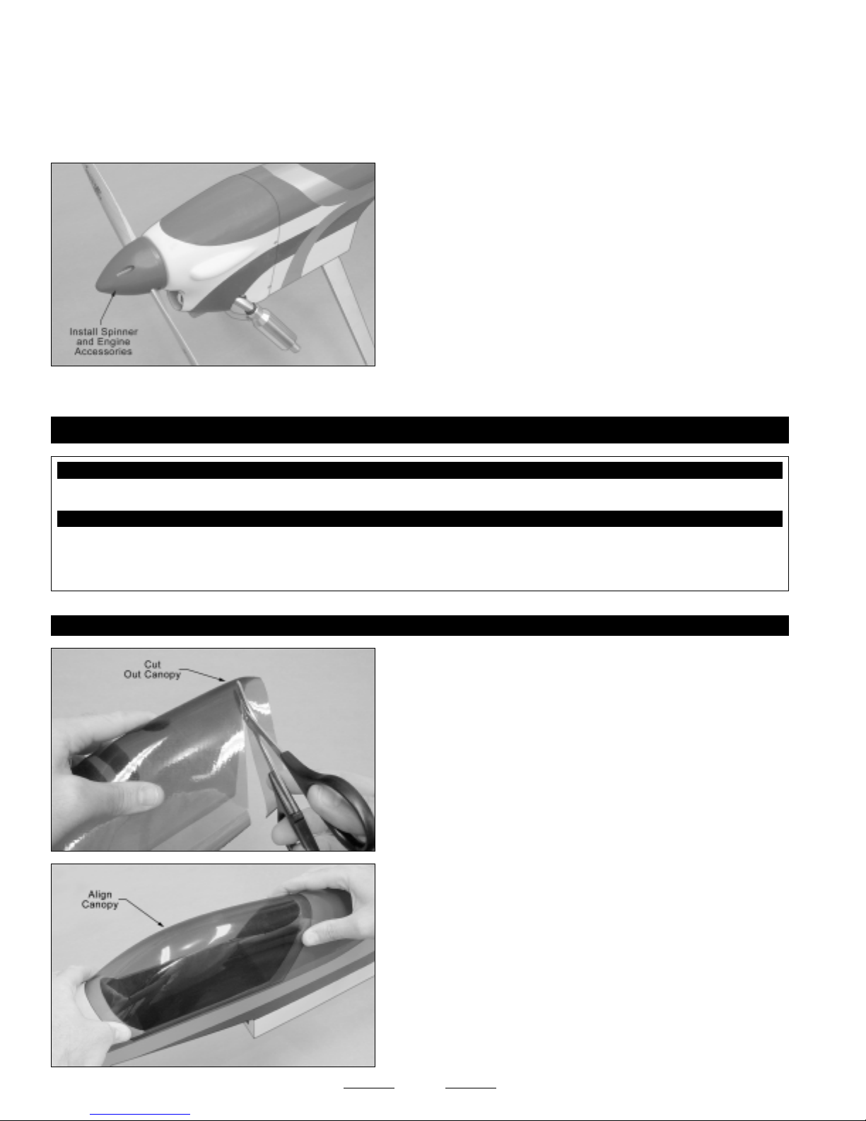
❑ At this time you should mark and cut out the areas of the cowling necessary to give you access to your engine's high and low
speed needle valves and choke lever (if featured). You should also install a fueling valve into a convenient location on the side
of the cowling, so that you can fill the fuel tank.
❑ To strengthen the holes in the fuselage that the wood screws will thread into, carefully apply a couple of drops of thin C/A into
the holes and let it dry completely before installing the cowling.
❑ Connect the fuel lines from the fuel tank to your engine's carburetor,
muffler and fueling valve.
❑ Slide the cowling into position and realign it. Install and tighten the
four M3 x 5mm wood screws to hold the cowling firmly in place.
❑ Install your high speed needle valve and propeller, then install the
spinner cone, using the two screws provided.
SECTION 19: CANOPY INSTALLATION
YOU'LL NEED THE FOLLOWING PARTS FROM THE KIT:
❑ (1) Molded Canopy
YOU'LL NEED THE FOLLOWING TOOLS AND SUPPLIES:
❑ Pacer Formula 560 Canopy Glue
❑ Scissors
❑ 220 Grit Sandpaper w/Sanding Block
STEP 1: ALIGNING AND INSTALLING THE CANOPY
❑ Masking Tape
❑ Paper Towels
❑ Using a pair of scissors, carefully cut out the canopy along the molded
scribe line.
❑ Using 220 grit sandpaper with a sanding block, carefully sand the
edges of the canopy smooth and straight.
❑ Set the canopy onto the fuselage and align it. When aligned
properly, the edges of the canopy should be centered over the cockpit
area and the canopy should be centered from side-to-side when viewed
from the front.
38
Continued On Next Page
☛☛
☛
☛☛

Before gluing the canopy into place, clean the inside of it to remove any fingerprints, dust and small debris.
☞
❑ When satisfied with the alignment, carefully glue the canopy into place, using a thin layer of Pacer Formula 560 Canopy Glue.
Remove any excess glue before it dries, using a paper towel and water, and use pieces of masking tape to hold the canopy in
place until the glue fully cures.
SECTION 20: FINAL ASSEMBLY
YOU'LL NEED THE FOLLOWING PARTS FROM THE KIT:
❑ (1) Decal Set
YOU'LL NEED THE FOLLOWING TOOLS AND SUPPLIES:
❑ # 1 Phillips Head Screwdriver
❑ Excel Modeling Knife
❑ Scissors
STEP 1: INSTALLING THE RECEIVER, BATTERY PACK AND SWITCH
❑ Electric Drill
❑ 5/64" Drill Bit
❑ Masking Tape
✦✦
✦IMPORTANT
✦✦
How the airplane initially balances will determine where you need to mount the receiver and battery pack.
❑ Wrap the receiver and battery pack in foam rubber to protect them from vibration. Use masking tape or rubber bands to hold the
foam in place. Do not wrap the foam rubber too tightly or the vibration dampening quality will be reduced.
❑ After you've found the final location of the receiver and battery pack, mount them into the fuselage using your favorite method.
Strips of Velcro
flat battery pack can be mounted in the fuel tank compartment, if necessary.
✦✦
✦IMPORTANT
✦✦
compartment to balance the airplane.
❑ After installing the receiver, drill a 5/64" diameter hole through the fuselage floor (behind the wing saddle) for the antenna to exit.
Unwrap the receiver antenna and feed it out through the hole.
✦✦
✦ We don't suggest permanently installing the receiver and battery pack until you have balanced the airplane.
✦✦
®
work well or sandwich them in place using a couple of scraps of balsa wood glued between the fuselage sides. A
✦✦
✦ If you're using a lightweight two-stroke engine, it may be necessary to mount the battery pack in the fuel tank
✦✦
❑ Using a modeling knife, carefully make an antenna mount out of an
extra servo horn. Remove one of the arms and cut it into the shape shown.
❑ Use the modified servo arm and a rubber band to secure the end of
the antenna to the tail skid.
❑ Mount the switch to the fuselage side (opposite the muffler) and connect the battery lead to the switch, and the switch and servo
leads to the receiver.
✦✦
✦IMPORTANT
✦✦
otherwise get caught in the rudder pushrods. You should take measures to secure the servo leads, so they can't get tangled in the
rudder pushrods during flight.
STEP 2: APPLYING THE DECALS
❑ Using a clean cloth, wipe the airframe down completely to remove any dust, oil and fingerprints, then cut out each of the decals
and apply them to the airframe, using the box cover photos for reference.
✦✦
✦ Make sure that the servo leads (including the aileron servo leads when the wing is installed) cannot interfere or
✦✦
39

SECTION 21: BALANCING THE MAGIC FORMULA 3D ARF
YOU'LL NEED THE FOLLOWING TOOLS AND SUPPLIES:
❑ # 2 Phillips Screwdriver
❑ Ruler
❑ Masking Tape
✦✦
✦
✦✦
IMPORTANT
and crash!
✦✦
✦
✦✦
It is critical that your airplane be balanced correctly. Improper balance will cause your airplane to lose control
Center of Gravity Location:
4-1/2" - 5-1/2" (114mm-140mm) back from the leading edge of the wing, measured at the fuselage sides.
✦✦
✦
✦✦
WARNING
(114mm), then move it farther back as you become familiar with the flying characteristics of the airplane. It is not recommended
that the C/G be located any farther back than 5-1/2" (140mm).
✦✦
✦IMPORTANT
✦✦
❑ Install the wing onto the fuselage.
❑ Apply two short pieces of masking tape onto the top of the wing, 4-1/2" (114mm) back from the leading edge, measured at
the fuselage sides.
❑ Turn the airplane upside down, place your fingers on the masking tape, and carefully lift the airplane. If the nose of the airplane
falls, the airplane is nose heavy. To correct this, move the battery pack and/or receiver back far enough to bring the airplane into
balance. If the tail of the airplane falls, the airplane is tail heavy. To correct this, move the battery pack and/or receiver forward far
enough to bring the airplane into balance. When balanced correctly, the airplane should sit level or slightly nose down when you lift
it up with your fingers at the C/G location.
Once you have flown and become familiar with the flight characteristics of the airplane, the C/G can be moved fore or aft within
☞
the C/G range to change the flight performance. Moving the C/G back will cause the airplane to be more responsive, but less stable.
Moving the C/G forward will cause the airplane to be more stable, but less responsive.
✦✦
✦
✦✦
This is the recommended C/G range. FOR TEST-FLYING WE SUGGEST YOU START WITH THE C/G AT 4-1/2"
✦✦
✦ Balance the Magic Formula 3D ARF with the fuel tank empty and the airplane fully assembled.
✦✦
DO NOT FLY THE AIRPLANE BEYOND THE RECOMMENDED BALANCE RANGE OR AN
UNCONTROLLABLE CRASH COULD RESULT!
SECTION 22: LATERAL BALANCING THE MAGIC FORMULA 3D ARF
Lateral balancing will make the airplane's controls easier to trim and will make the airplane track straighter in the air. It is
☞
strongly recommended.
❑ Turn the airplane upside down and tie one length of string to the propeller shaft and one length of string to the tail skid.
❑ With someone helping you, carefully lift the airplane up by the two pieces of string. Watch how the wing reacts. If one side of the
wing drops, that side is heavier than the other. To correct this condition, stick a small piece of self-adhesive lead weight to the
bottom of the lighter wing half (the one that doesn't drop).
✦✦
✦IMPORTANT
✦✦
✦✦
✦WARNING
✦✦
❑ Repeat the procedure a couple of more times to double-check your findings. When done properly the wing should stay level
when you lift the airplane.
✦✦
✦ For best mechanical advantage, place the weight as close to the wing tip as possible.
✦✦
✦✦
✦ Make sure to apply the lead weight to a solid portion of the wing structure so that it can't rip off during flight.
✦✦
40
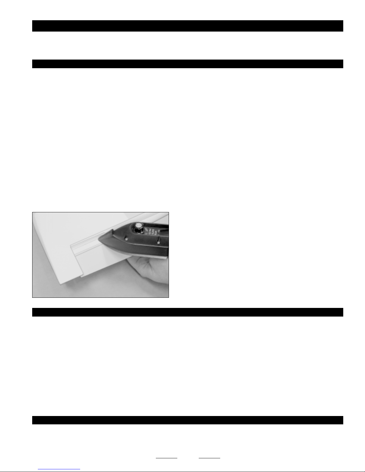
SECTION 23: AIRCRAFT SETUP INFORMATION
Before adjusting the control throws and flying your new Magic Formula 3D ARF, there are some points about the airplane's setup
that you should be aware of. We strongly suggest following these suggestions to get the most enjoyment out of your airplane.
SEALING THE HINGE GAPS
Because of the large control surfaces, it is imperative that the aileron and elevator hinge gaps be sealed. Failure to do this can lead
to control surface flutter, which can cause your airplane to crash. Sealing the hinge gaps will also provide crisper control response
and the airplane will track straighter and fly truer, making trimming much easier.
While the elevator and aileron hinge gaps should be sealed, it's not necessary to seal the rudder hinge gap, although you
☞
certainly could if you wanted to.
Hinge gaps can be sealed using heat-shrink covering material or clear vinyl tape. To seal the hinge gaps using heat-shrink covering
material, follow these steps:
❑ Cut a piece of covering material 1" wide and the same length as the hinge gap you're going to seal.
❑ Fold the length of covering material in half lengthwise so that there is a sharp crease down the middle of the covering material.
The hinge gap sealing material should be applied to only the bottom of the hinged surfaces. It is not necessary to seal both the
☞
bottom and the top.
❑ Remove the protective backing from the covering material. With the control surface fully deflected in the "UP" position, place the
length of covering material over the hinge line (on the bottom), making sure that the crease is pushed completely down into the hinge line.
❑ With the control surface fully deflected in the "UP" position, use a
heat sealing iron to carefully adhere the covering material to both the
trailing edge of the flying surface and the leading edge bevel of the
control surface. Use a modeling knife to trim the excess covering
material flush with both surfaces.
❑ Pivot the control surface up and down several times to check for free
movement. The control surface should be able to smoothly pivot
completely up and completely down, without interference from the hinge
Photo Shown May Look Different
Than Actual Model
CONTROL SURFACE LINKAGES
If you don't maintain the proper mechanical advantage on the control surfaces, control surface flutter may result, which can cause
your airplane to lose control and crash. Mechanical advantage refers to the distance that the pushrod attachment points (pivot
points) are from the servos and the control surfaces.
●
Keeping the pushrods as close to the center of the servo arms as possible will increase the servo's resolution. What this means
is that when you move the control sticks on the transmitter, the servo arms will have to travel farther to achieve the desired amount
of control input. This makes the resolution higher, therefore causing the control surface deflection to be more precise. We don't
recommend moving the pushrods any farther away from the center of the servo arms than absolutely necessary.
●
Keeping the pushrods as far away as possible from the control surfaces is better than moving them closer. The mechanical
advantage is greatly reduced the closer the pushrods are moved toward the control surfaces. We don't recommend moving the
pushrods any closer to the control surfaces than absolutely necessary.
gap sealing material.
THROTTLE MANAGEMENT
It is very important that you understand throttle management. Basically, this means no full throttle dives. Full throttle
dives should be avoided so as not to cause control surface flutter and/or airframe failure. When the nose of the airplane
drops, decrease the throttle, just as in full-scale aerobatics.
41

SECTION 24: CONTROL THROWS
We recommend initially setting up the Magic Formula 3D ARF using the Test-Flying control throws. These control throws are
suggested for initial test-flying and general sport-flying because they will allow the airplane to fly smoother and make it easier to
control. For general aerobatic flight, use the Sport-Flying control throws, but only AFTER you've become familiar with the flight
characteristics of the airplane using the Test-Flying control throws.
TEST-FLYING
Ailerons: 1-1/4" (32mm) Up & Down
Elevator: 1-1/2" (38mm) Up & Down
Rudder: 1-5/8" (40mm) Right & Left
The control throws listed are a good starting point for test-flying and aerobatics. Of course, you can adjust these control
throws to suit your particular style and tastes, but realize that the airplane will be extremely control sensitive and more
difficult to control with higher control throws.
✦✦
✦IMPORTANT
✦✦
✦✦
✦VERY IMPORTANT
✦✦
of the clear tubing provided and sliding one piece over each clevis and 90º snap-keeper. The tubing will prevent any chance of the
clevises and snap-keepers opening during flight.
✦✦
✦VERY IMPORTANT
✦✦
throws unless you are a proficient flyer. Higher control throws will cause the airplane to be extremely control sensitive and result in
a possible crash if you are not careful.
✦✦
✦ The control throws are measured from the widest point of the control surfaces.
✦✦
✦✦
✦ After you are finished adjusting the pushrods and control throws, we strongly suggest cutting 1/4" lengths
✦✦
✦✦
✦ We do not suggest increasing the control throws beyond the recommended Sport-Flying control
✦✦
Ailerons: 1-3/4" (45mm) Up & Down
Elevator: 1-3/4" (45mm) Up & Down
Rudder: 2" (50mm) Right & Left
SPORT-FLYING
SECTION 25: COMPUTER RADIO SETUP AND 3D CONTROL THROWS
Although you don't have to use a computer radio to enjoy the flying qualities of the Magic Formula 3D ARF, if you're planning on
doing extreme 3D aerobatics, it is recommended. Before making any adjustments, please read and understand your radio's
setup manual.
✦✦
✦READ THIS BEFORE GOING FURTHER
✦✦
The 3D aerobatic control throws listed below make the airplane extremely control sensitive. Use these control throws only if you
have a computer radio that you can program exponential and dual rates into. Your radio system must have the capability to turn
these control throws off during normal flight and turn them on before flying 3D maneuvers. Normal flying does not require this
amount of control throw.
3D CONTROL THROWS
Ailerons: 2-3/8" (60mm) Up & Down
Elevator: 3-7/8" (100mm) Up & Down
Rudder: As Much as Possible Right & Left
EXPONENTIAL:
Expo, as it's more commonly referred to, softens the control feel around neutral. This is especially helpful when flying an airplane
that uses a lot of control throw. Softening the neutral point makes the airplane fly more smoothly and makes it more likely that
you won't over-control.
Obviously, you may want to change the expo settings to suit your flying style, but here are some good starting points:
Ailerons: 40%
Elevator: 30%
Rudder: 20%
Because of the extreme control surface throw using the 3D control throws, you must
program exponential into the control surfaces. It will soften the control sensitivity around
neutral, making the airplane smoother and easier to control.
✦✦
✦
✦✦
For 3D flying, we suggest moving the C/G back further than
the test-flying position. Move the C/G back to 5", then get a
feel for the airplane. You can continue to move it back from
there to suit your flying style, but we strongly caution you to
not move the C/G further back than 5-1/2".
42
Continued On Next Page
☛☛
☛
☛☛

FLAPERON AND SPOILERON MIXING:
Plugging the servos separately into the receiver (one into channel 1 and one into channel 6) will allow the use of flaperons (both
ailerons down at the same time) and spoilerons (both ailerons up at the same time). These functions can then be mixed with the
elevator for extreme pitch changes (high-alpha) useful in extreme 3D aerobatic maneuvers. These recommendations are for
3D flying only.
Elevator: 3-7/8" (100mm) Up and Spoilerons (both ailerons up) 2-3/4" (70mm)
Elevator: 3-7/8" (100mm) Down and Flaperons (both ailerons down) 2-3/4" (70mm)
✦✦
✦IMPORTANT
✦✦
✦✦
✦ We do not recommend using flaperon and spoileron with elevator mixing during general flying, especially
✦✦
during takeoff and landing.
ADDING TAIL BRACES:
The construction of the Magic Formula 3D is very strong; however, if you wish to add tail bracing (flying wires) to the horizontal and
vertical stabilizers, we have provided hardpoints to mount them.
SECTION 26: PREFLIGHT CHECK AND SAFETY
●
Completely charge the transmitter and receiver batteries before your first day of flying.
●
Check every bolt and every glue joint in the airplane to ensure that everything is tight and well-bonded. This should
include all of the control surface hinges as well.
●
Double-check that you've installed and tightened all of the servo horn retaining screws.
●
Double-check that the receiver and battery pack are properly secured into the fuselage. There's nothing worse than the
battery pack coming loose during a violent aerobatic maneuver.
●
Double-check that the fuel tank is properly secured into the fuselage.
●
Double-check the balance of the airplane. Do this with the fuel tank EMPTY.
●
Check the control surfaces. They should all move in the correct direction and not bind.
●
Make sure that you've installed 1/4" long pieces of clear tubing over the clevises and snap-keepers to prevent any chance of
them opening during flight.
●
If your radio transmitter is equipped with dual rate switches, double-check that they are on the low-rate setting for your first
few flights.
●
Check to ensure that all of the control surfaces are moving the proper amount in both low and high rate settings.
●
Check the receiver antenna. It should be fully extended and not coiled up inside the fuselage. Do not cut the receiver antenna
shorter or the range of your radio control system will be greatly reduced.
●
Properly balance the propeller. A propeller that is out of balance will cause excessive vibration, which could lead to engine
and/or airframe failure, and it will reduce engine efficiency and power.
43

SECTION 27: MAGIC FORMULA 3D ARF FLIGHT-TRIMMING CHART
After you have test-flown and done the initial trim changes to the airplane, use this trimming chart to begin trimming your airplane.
Following and adhering to this chart will result in the ability to diagnose trim problems and correct those problems using the simple
adjustments shown below. Making these observations and related corrections will result in an airplane that tracks straighter and
flies truer.
TRIM FEATURE MANEUVER OBSERVATION CORRECTION
Control Centering Fly general circles and random
maneuvers
Control Throws Fly random maneuvers A) Controls are too sensitive or
Engine Thrust Angle* From straight and level flight, quickly
chop the throttle for a short distance
Center of Gravity From level flight, roll to a 45º bank and
neutralize the controls
Yaw** Into the wind, perform inside loops
using only elevator. Repeat test
performing outside loops from an
inverted entry
Try for hands off straight and level flight Readjust linkages so the transmitter
airplane feels "jerky"
B) Controls are not sensitive enough
or airplane feels "mushy"
A) Airplane continues in a level attitude
for a short distance
B) Airplane pitches nose up
C) Airplane pitches nose down
A) Airplane continues in the bank for
a short distance
B) Nose pitches up
C) Nose pitches down
A) Wing is level throughout
B) Airplane yaws to right in both inside
and outside loops
C) Airplane yaws to left in both inside
and outside loops
D) Airplane yaws to the right in inside
loops and yaws to the left in
out side loops
E) Airplane yaws to the left in inside
loops and yaws to the right in
outside loops
trim levers are centered
If A) Adjust linkages to reduce
control throws
If B) Adjust linkages to increase
control throws
If A) Engine thrust angle is correct
If B) Decrease engine down thrust
If C) Increase engine down thrust
If A) Center of gravity is correct
If B) Add nose weight
If C) Remove nose weight or add tail
weight
If A) Trim settings are correct
If B) Add left rudder trim
If C) Add right rudder trim
If D) Add left aileron trim
If E) Add right aileron trim
Lateral Balance** Into the wind, perform tight inside loops
using only elevator
Aileron Control System With the wing level, pull to a vertical
climb and neutralize the controls
*Engine thrust angle and center of gravity interact. Check both.
**Yaw and lateral balance produce similar symptoms. Note that the fin may be crooked. Make certain both elevator halves are even with
each other and that they both produce the same amount of control deflection throughout the complete deflection range. Right and left
references are as if you were in the cockpit.
A) Wing is level and airplane falls
to either side
B) Airplane falls off to the left.
Worsens as loops tighten
C) Airplane falls off to the right.
Worsens as loops tighten
A) Climb continues along the same
path
B) Nose tends to go toward an inside
loop
C) Nose tends to go toward an outside
loop
44
If A) Lateral balance is correct
If B) Add weight to right wing tip
If C) Add weight to left wing tip
If A) Trim settings are correct
If B) Raise both ailerons very slightly
If C) Lower both ailerons very slightly

SECTION 28: REPLACEMENT PARTS
We stock a complete line of replacement parts for your Model Tech Magic Formula 3D ARF. Listed below are the replacement parts
that are available along with their respective part numbers for easy ordering convenience. We suggest ordering directly from your
local dealer.
If your dealer does not stock Model Tech or Global products, you can order replacement parts
directly from us, using the Customer Service Information on page # 3.
Magic Formula 3D ARF - Complete...............................123771
Instruction Manual ......................................................... 120265
Wing Set ........................................................................ 120266
Fuselage Set .................................................................. 120267
Stabilizer Set .................................................................. 120268
Belly Pan ........................................................................120269
Canopy ........................................................................... 120270
Tail Skid .......................................................................... 120271
Fuel Tank (320cc) .......................................................... 120272
Landing Gear Bracket .................................................... 120273
Cowling .......................................................................... 120274
Wheel Pants .................................................................. 120275
Hardware Set ................................................................. 120276
Decal Set ....................................................................... 120277
Spinner Assembly .......................................................... 120278
Engine Mount Set .......................................................... 120279
45

46

PRODUCT EVALUATION SHEET
Telling us what you like and don't like determines what model kits we make and how we make them. We would appreciate it if you would
take a few minutes of your time to answer the following questions about this kit and your modeling interests. Simply fold this form on the
dotted lines, seal with tape and mail it to us. Do not use staples and make sure our address faces out.
Global Hobby Distributors will not disclose the information it collects to outside parties. Global Hobby Distributors does not sell,
trade, or rent your personal information to others. Your privacy is important to us.
1) Kit: Model Tech Magic Formula 3D ARF # 123771
2) Where did you learn about this kit?
❑ Magazine Ads ❑ Friend
❑ Hobby Shop ❑ Other
❑ Internet
3) What influenced you the most to buy this kit?
❑ Magazine Ads ❑ Price
❑ Type of Model ❑ Box Art
❑ Recommendation ❑ Other
❑ Internet
4) Did you have any trouble understanding the written
instructions? If yes, please explain.
❑ Yes ❑ No
____________________________________
____________________________________
____________________________________
____________________________________
5) Did you have any trouble understanding any of the
photographs? If yes, please explain.
❑ Yes ❑ No
____________________________________
____________________________________
____________________________________
6) Were any of the kit parts:
Cut Along Dotted Line
❑ Damaged ❑ Wrong Size
❑ Missing ❑ Wrong Shape
If you checked any of the boxes above, did you
contact our Customer Service Department to resolve
the problem?
❑ Yes ❑ No
7) Was any of the assembly difficult for you? If yes,
please explain.
❑ Yes ❑ No
____________________________________
____________________________________
____________________________________
____________________________________
8) What did you like most about this kit?
❑ Assembly Manual ❑ Parts Fit
❑ Hardware Supplied ❑ Price
❑ Other
____________________________________
____________________________________
____________________________________
9) What did you like least about this kit?
❑ Assembly Manual ❑ Parts Fit
❑ Hardware Supplied ❑ Price
❑ Other
____________________________________
____________________________________
____________________________________
10) Are you satisfied with the finished model? If no,
please explain.
❑ Yes ❑ No
____________________________________
____________________________________
____________________________________
____________________________________
11) How does this kit compare to similar kits by other
manufacturers?
❑ Better ❑ As Good
What is Your Age Group:
❑ 10 & Under ❑ 11 - 20 ❑ 21 - 30 ❑ 31 - 40 ❑ 41 - 50 ❑ 51 - 60 ❑ 61 - 70 ❑ 71 +
How Many Years Have You Been in the Hobby?
❑ Less than 1 ❑ 2 - 4 ❑ 5 - 7 ❑ 8 - 10 ❑ 11 - 15 ❑ 16 - 20 ❑ 20 or More
How Many Models Have You Purchased In the Last Year?
❑ 0 - 1 ❑ 2 - 4 ❑ 5 - 7 ❑ 8 - 10 ❑ 10 or More
Please List any Other Modeling Interests or any Additional Information about This Product: ______________________
_____________________________________________________________________________________
_____________________________________________________________________________________
_____________________________________________________________________________________
_____________________________________________________________________________________
The Model Tech Magic Formula 3D ARF is distributed exclusively by
Global Hobby Distributors 18480 Bandilier Circle, Fountain Valley, CA 92708
All contents copyright © 2004, Global Hobby Distributors
Version V1.0 December 2004
QC #
47

_____________________________
_____________________________
_____________________________
(Return Address Here)
Global Hobby Distributors
Attn: Global Services
18480 Bandilier Circle
Fountain Valley CA 92728-8610
Fold along dotted line
Fold along dotted line
Post Office will
not deliver
without proper
postage
48
 Loading...