

Page 1

ModelSim®
Xilinx Edition II
User’s Manual
Version 5.7c
Published: 11/Mar/03
The world’s most popular HDL simulator
Page 2

ii
ModelSim is produced by Model Technology™, a Mentor Graphics Corporation
company. Copying, duplication, or other reproduction is prohibited without the
written consent of Model Technology.
The information in this manual is subject to change without notice and does not
represent a commitment on the part of Model Technology. The program described
in this manual is furnished under a license agreement and may not be used or
copied except in accordance with the terms of the agreement. The online
documentation provided with this product may be printed by the end-user. The
number of copies that may be printed is limited to the number of licenses
purchased.
ModelSim is a registered trademark and Signal Spy, TraceX, ChaseX and Model
Technology are trademarks of Mentor Graphics Corporation. PostScript is a
registered trademark of Adobe Systems Incorporated. UNIX is a registered
trademark of AT&T in the USA and other countries. FLEXlm is a trademark of
Globetrotter Software, Inc. IBM, AT, and PC are registered trademarks, AIX and
RISC System/6000 are trademarks of International Business Machines
Corporation. Windows, Microsoft, and MS-DOS are registered trademarks of
Microsoft Corporation. OSF/Motif is a trademark of the Open Software Foundation,
Inc. in the USA and other countries. SPARC is a registered trademark and
SPARCstation is a trademark of SPARC International, Inc. Sun Microsystems is a
registered trademark, and Sun
, SunOS and OpenWindows are trademarks of Sun
Microsystems, Inc. All other trademarks and registered trademarks are the
properties of their respective holders.
Copyright
© 1990 -2003, Model Technology, a Mentor Graphics Corporation
company. All rights reserved. Confidential. Online documentation may be printed
by licensed customers of Model Technology and Mentor Graphics for internal
business purposes on ly.
ModelSim support
Support for ModelSim is available from your FPGA vendor. See the About
ModelSim dialog box (accessed via the Help menu) for contact information.
ModelSim User’s Manual
Page 3

Table of Contents
1 - Introduction (UM-13)
Standards supported . . . . . . . . . . . . . . . . . . . . . . . . . . . . . . UM-14
Assumptions . . . . . . . . . . . . . . . . . . . . . . . . . . . . . . . . . UM-14
Sections in this document . . . . . . . . . . . . . . . . . . . . . . . . . . . . UM-14
What is an "HDL item" . . . . . . . . . . . . . . . . . . . . . . . . . . . . . UM-16
Text conventions . . . . . . . . . . . . . . . . . . . . . . . . . . . . . . . UM-16
2 - Projects (UM-17)
Introduction . . . . . . . . . . . . . . . . . . . . . . . . . . . . . . . . . UM-18
How do proje cts differ from pre-5.5 version s? . . . . . . . . . . . . . . . . . . UM-19
Project conversion between versions . . . . . . . . . . . . . . . . . . . . . . UM-19
Getting started with projects . . . . . . . . . . . . . . . . . . . . . . . . . . . UM-20
Step 1 — Creating a new project . . . . . . . . . . . . . . . . . . . . . . . UM-20
Step 2 — Adding items to the project . . . . . . . . . . . . . . . . . . . . . UM-21
Step 3 — Compiling the files . . . . . . . . . . . . . . . . . . . . . . . . . UM-24
Step 4 — Simula t ing a design . . . . . . . . . . . . . . . . . . . . . . . . UM-25
Other basic project operations . . . . . . . . . . . . . . . . . . . . . . . . UM-25
The Project tab . . . . . . . . . . . . . . . . . . . . . . . . . . . . . . . . UM-26
Project tab context menu . . . . . . . . . . . . . . . . . . . . . . . . . . UM-27
Changing compile order . . . . . . . . . . . . . . . . . . . . . . . . . . . . UM-28
Grouping files . . . . . . . . . . . . . . . . . . . . . . . . . . . . . . . UM-29
Creating a Simulation Configuration . . . . . . . . . . . . . . . . . . . . . . . . UM-30
Organizing projects with folders . . . . . . . . . . . . . . . . . . . . . . . . . UM-32
Setting compiler options . . . . . . . . . . . . . . . . . . . . . . . . . . . . UM-34
Accessing projects from the command line . . . . . . . . . . . . . . . . . . . . . UM-35
UM-3
3 - Design libraries (UM-37)
Design library contents . . . . . . . . . . . . . . . . . . . . . . . . . . . . . UM-38
Design library types . . . . . . . . . . . . . . . . . . . . . . . . . . . . . . UM-39
Working with design libraries . . . . . . . . . . . . . . . . . . . . . . . . . . UM-40
Managing library contents . . . . . . . . . . . . . . . . . . . . . . . . . . UM-41
Assigning a logical name to a design library . . . . . . . . . . . . . . . . . . . UM-43
Moving a library . . . . . . . . . . . . . . . . . . . . . . . . . . . . . . UM-44
Specifying the resource libraries . . . . . . . . . . . . . . . . . . . . . . . . . UM-45
Predefined libraries . . . . . . . . . . . . . . . . . . . . . . . . . . . . . UM-46
Alternate IEEE libraries supplied . . . . . . . . . . . . . . . . . . . . . . . UM-46
Regenerating your design libraries . . . . . . . . . . . . . . . . . . . . . . . UM-47
Importing FPGA libraries . . . . . . . . . . . . . . . . . . . . . . . . . . . . UM-48
ModelSim User’s Manual
Page 4

UM-4 Table of Contents
4 - VHDL simulation (UM-49)
Compiling VHDL designs . . . . . . . . . . . . . . . . . . . . . . . . . . . . UM-50
Invoking the VHDL compiler . . . . . . . . . . . . . . . . . . . . . . . . UM-50
Dependency checking . . . . . . . . . . . . . . . . . . . . . . . . . . . . UM-50
Range and index checking . . . . . . . . . . . . . . . . . . . . . . . . . . UM-50
Simulating VHDL designs . . . . . . . . . . . . . . . . . . . . . . . . . . . . UM-52
Simulator resolution limit . . . . . . . . . . . . . . . . . . . . . . . . . . UM-52
Delta delays . . . . . . . . . . . . . . . . . . . . . . . . . . . . . . . UM-53
Using the TextIO package . . . . . . . . . . . . . . . . . . . . . . . . . . . . UM-55
Syntax for file declaration . . . . . . . . . . . . . . . . . . . . . . . . . . UM-55
Using STD_INPUT and STD_OUTPUT within ModelSim . . . . . . . . . . . . . UM-56
TextIO implementation issues . . . . . . . . . . . . . . . . . . . . . . . . . . UM-57
Reading and writing hexadecimal numbers . . . . . . . . . . . . . . . . . . . UM-58
Dangling pointers . . . . . . . . . . . . . . . . . . . . . . . . . . . . . UM-58
The ENDLINE function . . . . . . . . . . . . . . . . . . . . . . . . . . . UM-58
The ENDFILE function . . . . . . . . . . . . . . . . . . . . . . . . . . . UM-58
Using alternative input/output files . . . . . . . . . . . . . . . . . . . . . . UM-59
Providing st imulus . . . . . . . . . . . . . . . . . . . . . . . . . . . . . UM-59
VITAL specification and source code . . . . . . . . . . . . . . . . . . . . . . . UM-60
VITAL packages . . . . . . . . . . . . . . . . . . . . . . . . . . . . . . . UM-60
ModelSim VITAL compliance . . . . . . . . . . . . . . . . . . . . . . . . . . UM-60
VITAL compliance checking . . . . . . . . . . . . . . . . . . . . . . . . . UM-60
Compiling and simulating with accelerated VITAL packages . . . . . . . . . . . . . . UM-61
Util package . . . . . . . . . . . . . . . . . . . . . . . . . . . . . . . . . UM-62
get_resolution . . . . . . . . . . . . . . . . . . . . . . . . . . . . . . . UM-62
init_signal_driver() . . . . . . . . . . . . . . . . . . . . . . . . . . . . . UM-63
init_signal_spy() . . . . . . . . . . . . . . . . . . . . . . . . . . . . . . UM-63
signal_force() . . . . . . . . . . . . . . . . . . . . . . . . . . . . . . . UM-63
signal_release() . . . . . . . . . . . . . . . . . . . . . . . . . . . . . . UM-63
to_real() . . . . . . . . . . . . . . . . . . . . . . . . . . . . . . . . . UM-64
to_time() . . . . . . . . . . . . . . . . . . . . . . . . . . . . . . . . . UM-65
5 - Verilog simulation (UM-67)
Compilation . . . . . . . . . . . . . . . . . . . . . . . . . . . . . . . . . UM-69
Incremental compilation . . . . . . . . . . . . . . . . . . . . . . . . . . . UM-70
Library usage . . . . . . . . . . . . . . . . . . . . . . . . . . . . . . . UM-72
Verilog-XL compatible compiler arguments . . . . . . . . . . . . . . . . . . . UM-73
Verilog-XL ‘uselib compiler directive . . . . . . . . . . . . . . . . . . . . . UM-74
Simulation . . . . . . . . . . . . . . . . . . . . . . . . . . . . . . . . . . UM-76
Simulator resolution limit . . . . . . . . . . . . . . . . . . . . . . . . . . UM-77
Event ordering in Verilog designs . . . . . . . . . . . . . . . . . . . . . . . UM-79
Negative timing check limits . . . . . . . . . . . . . . . . . . . . . . . . . UM-83
Verilog-XL compatible simulator arguments . . . . . . . . . . . . . . . . . . . UM-86
Cell libraries . . . . . . . . . . . . . . . . . . . . . . . . . . . . . . . . . UM-87
Delay modes . . . . . . . . . . . . . . . . . . . . . . . . . . . . . . . UM-87
ModelSim User’s Manual
Page 5

System tasks . . . . . . . . . . . . . . . . . . . . . . . . . . . . . . . . . UM-89
IEEE Std 1364 system tasks . . . . . . . . . . . . . . . . . . . . . . . . . UM-89
Verilog-XL compatible system tasks . . . . . . . . . . . . . . . . . . . . . . UM-92
ModelSim Verilog system tasks . . . . . . . . . . . . . . . . . . . . . . . . UM-94
Compiler directives . . . . . . . . . . . . . . . . . . . . . . . . . . . . . . UM-95
IEEE Std 1364 compiler directives . . . . . . . . . . . . . . . . . . . . . . UM-95
Verilog-XL compatible compiler directives . . . . . . . . . . . . . . . . . . . UM-96
Verilog PLI/VPI . . . . . . . . . . . . . . . . . . . . . . . . . . . . . . . . UM-97
Registering PLI applications . . . . . . . . . . . . . . . . . . . . . . . . . UM-97
Registering VPI applications . . . . . . . . . . . . . . . . . . . . . . . . . UM-99
Compiling and linking PLI/VPI C applications . . . . . . . . . . . . . . . . . UM-101
Compiling and linking PLI/VPI C++ applications . . . . . . . . . . . . . . . . UM-102
Specifying the PLI/VPI file to load . . . . . . . . . . . . . . . . . . . . . UM-103
PLI example . . . . . . . . . . . . . . . . . . . . . . . . . . . . . . UM-104
VPI example . . . . . . . . . . . . . . . . . . . . . . . . . . . . . . UM-105
The PLI callback reason argument . . . . . . . . . . . . . . . . . . . . . . UM-106
The sizetf callback function . . . . . . . . . . . . . . . . . . . . . . . . UM-107
PLI object handles . . . . . . . . . . . . . . . . . . . . . . . . . . . . UM-107
Third party PLI applications . . . . . . . . . . . . . . . . . . . . . . . . UM-108
Support for VHDL objects . . . . . . . . . . . . . . . . . . . . . . . . . UM-109
IEEE Std 1364 ACC routines . . . . . . . . . . . . . . . . . . . . . . . . UM-110
IEEE Std 1364 TF routines . . . . . . . . . . . . . . . . . . . . . . . . . UM-111
Verilog-XL compatible routines . . . . . . . . . . . . . . . . . . . . . . . UM-113
64-bit support in the PLI . . . . . . . . . . . . . . . . . . . . . . . . . . UM-113
PLI/VPI tracing . . . . . . . . . . . . . . . . . . . . . . . . . . . . . UM-113
Debugging PLI/VPI application code . . . . . . . . . . . . . . . . . . . . UM-115
UM-5
6 - WLF files (datasets) and virtuals (UM-117)
WLF files (datasets) . . . . . . . . . . . . . . . . . . . . . . . . . . . . . UM-118
Saving a simulation to a WLF file . . . . . . . . . . . . . . . . . . . . . . UM-119
Opening datasets . . . . . . . . . . . . . . . . . . . . . . . . . . . . . UM-119
Viewing dataset structure . . . . . . . . . . . . . . . . . . . . . . . . . UM-120
Managing multiple datasets . . . . . . . . . . . . . . . . . . . . . . . . UM-121
Saving at intervals with Dataset Snapshot . . . . . . . . . . . . . . . . . . . UM-123
Virtual Objects (User-defined buses, and more) . . . . . . . . . . . . . . . . . . UM-125
Virtual signals . . . . . . . . . . . . . . . . . . . . . . . . . . . . . . UM-125
Virtual functions . . . . . . . . . . . . . . . . . . . . . . . . . . . . . UM-126
Virtual regions . . . . . . . . . . . . . . . . . . . . . . . . . . . . . UM-127
Virtual types . . . . . . . . . . . . . . . . . . . . . . . . . . . . . . UM-127
Dataset, WLF file, and virtual commands . . . . . . . . . . . . . . . . . . . . . UM-128
7 - Graphic interface (UM-129)
Window overview . . . . . . . . . . . . . . . . . . . . . . . . . . . . . . UM-130
Common window features . . . . . . . . . . . . . . . . . . . . . . . . . . . UM-131
Quick access toolbars . . . . . . . . . . . . . . . . . . . . . . . . . . . UM-132
Drag and Drop . . . . . . . . . . . . . . . . . . . . . . . . . . . . . UM-132
ModelSim User’s Manual
Page 6

UM-6 Table of Contents
Command his tory . . . . . . . . . . . . . . . . . . . . . . . . . . . . UM-132
Automatic window updating . . . . . . . . . . . . . . . . . . . . . . . . UM-133
Finding names . . . . . . . . . . . . . . . . . . . . . . . . . . . . . UM-133
Sorting HDL items . . . . . . . . . . . . . . . . . . . . . . . . . . . . UM-133
Saving window layout . . . . . . . . . . . . . . . . . . . . . . . . . . UM-134
Context menus . . . . . . . . . . . . . . . . . . . . . . . . . . . . . UM-134
Menu tear of f . . . . . . . . . . . . . . . . . . . . . . . . . . . . . . UM-134
Tree window hierarchical view . . . . . . . . . . . . . . . . . . . . . . . UM-135
Main window . . . . . . . . . . . . . . . . . . . . . . . . . . . . . . . . UM-137
Workspace . . . . . . . . . . . . . . . . . . . . . . . . . . . . . . . UM-138
Transcript . . . . . . . . . . . . . . . . . . . . . . . . . . . . . . . UM-139
The Main window menu bar . . . . . . . . . . . . . . . . . . . . . . . . UM-140
The Main window toolbar . . . . . . . . . . . . . . . . . . . . . . . . . UM-145
The Main window status bar . . . . . . . . . . . . . . . . . . . . . . . . UM-147
Mouse and keyboard shortcuts . . . . . . . . . . . . . . . . . . . . . . . UM-147
Dataflow window . . . . . . . . . . . . . . . . . . . . . . . . . . . . . . UM-149
Adding items to the window . . . . . . . . . . . . . . . . . . . . . . . . UM-149
Links to other windows . . . . . . . . . . . . . . . . . . . . . . . . . . UM-150
Dataflow window menu bar . . . . . . . . . . . . . . . . . . . . . . . . UM-150
The Dataflow window toolbar . . . . . . . . . . . . . . . . . . . . . . . UM-153
Exploring the connectivity of your design . . . . . . . . . . . . . . . . . . . UM-156
Zooming an d panning . . . . . . . . . . . . . . . . . . . . . . . . . . . UM-158
Tracing events (causality) . . . . . . . . . . . . . . . . . . . . . . . . . UM-159
Tracing the source of an unknown (X) . . . . . . . . . . . . . . . . . . . . UM-160
Finding items by name in the Dataflow window . . . . . . . . . . . . . . . . UM-161
Saving the display . . . . . . . . . . . . . . . . . . . . . . . . . . . . UM-162
Configuring page setup . . . . . . . . . . . . . . . . . . . . . . . . . . UM-164
Symbol mapping . . . . . . . . . . . . . . . . . . . . . . . . . . . . . UM-165
Configuring window options . . . . . . . . . . . . . . . . . . . . . . . . UM-166
List window . . . . . . . . . . . . . . . . . . . . . . . . . . . . . . . . UM-168
HDL items you can view . . . . . . . . . . . . . . . . . . . . . . . . . UM-168
Adding HDL items to the List window . . . . . . . . . . . . . . . . . . . . UM-169
The List window menu bar . . . . . . . . . . . . . . . . . . . . . . . . . UM-170
Editing and formatting HDL items in the List window . . . . . . . . . . . . . . UM-172
Combining items in the List window . . . . . . . . . . . . . . . . . . . . . UM-174
Setting List window display properties . . . . . . . . . . . . . . . . . . . . UM-175
Finding items by name in the List window . . . . . . . . . . . . . . . . . . UM-177
Setting time markers in the List window . . . . . . . . . . . . . . . . . . . UM-178
Saving List window data to a file . . . . . . . . . . . . . . . . . . . . . . UM-179
List window keyboard shortcuts . . . . . . . . . . . . . . . . . . . . . . . UM-180
Process window . . . . . . . . . . . . . . . . . . . . . . . . . . . . . . . UM-181
The Process window menu bar . . . . . . . . . . . . . . . . . . . . . . . UM-182
Signals window . . . . . . . . . . . . . . . . . . . . . . . . . . . . . . . UM-183
The Signals window menu bar . . . . . . . . . . . . . . . . . . . . . . . UM-184
Filtering the signal list . . . . . . . . . . . . . . . . . . . . . . . . . . UM-185
Forcing signal and net values . . . . . . . . . . . . . . . . . . . . . . . . UM-186
Adding HDL items to the Wave and List windows or a WLF file . . . . . . . . . . UM-187
Finding HDL items in the Signals window . . . . . . . . . . . . . . . . . . UM-188
Setting signal breakpoints . . . . . . . . . . . . . . . . . . . . . . . . . UM-189
ModelSim User’s Manual
Page 7

Defining cl ock signals . . . . . . . . . . . . . . . . . . . . . . . . . . UM-189
Source window . . . . . . . . . . . . . . . . . . . . . . . . . . . . . . . UM-191
The Source window menu bar . . . . . . . . . . . . . . . . . . . . . . . UM-192
The Source window toolbar . . . . . . . . . . . . . . . . . . . . . . . . UM-194
Setting file-line breakpoints . . . . . . . . . . . . . . . . . . . . . . . . UM-197
Checking HDL item values and descriptions . . . . . . . . . . . . . . . . . . UM-197
Finding and replacing in the Source window . . . . . . . . . . . . . . . . . . UM-197
Setting tab stops in the Source window . . . . . . . . . . . . . . . . . . . . UM-198
Structure window . . . . . . . . . . . . . . . . . . . . . . . . . . . . . . UM-199
Structure window menu bar . . . . . . . . . . . . . . . . . . . . . . . . UM-200
Structure window context menu . . . . . . . . . . . . . . . . . . . . . . . UM-201
Finding items in the Structure window . . . . . . . . . . . . . . . . . . . . UM-202
Variables window . . . . . . . . . . . . . . . . . . . . . . . . . . . . . . UM-203
The Variables window menu bar . . . . . . . . . . . . . . . . . . . . . . UM-204
Finding HDL items in the Variables window . . . . . . . . . . . . . . . . . . UM-205
Wave window . . . . . . . . . . . . . . . . . . . . . . . . . . . . . . . UM-206
Pathname pane . . . . . . . . . . . . . . . . . . . . . . . . . . . . . UM-206
Values pane . . . . . . . . . . . . . . . . . . . . . . . . . . . . . . UM-207
Waveform pane . . . . . . . . . . . . . . . . . . . . . . . . . . . . . UM-207
Cursor panes . . . . . . . . . . . . . . . . . . . . . . . . . . . . . . UM-207
HDL items you can view . . . . . . . . . . . . . . . . . . . . . . . . . UM-207
Adding HDL items in the Wave window . . . . . . . . . . . . . . . . . . . UM-208
The Wave window menu bar . . . . . . . . . . . . . . . . . . . . . . . . UM-209
The Wave window toolbar . . . . . . . . . . . . . . . . . . . . . . . . . UM-212
Using dividers . . . . . . . . . . . . . . . . . . . . . . . . . . . . . . UM-215
Splitting Wave window panes . . . . . . . . . . . . . . . . . . . . . . . UM-216
Combining items in the Wave window . . . . . . . . . . . . . . . . . . . . UM-217
Displaying drivers of the selected waveform . . . . . . . . . . . . . . . . . . UM-218
Editing and formatting HDL items in the Wave window . . . . . . . . . . . . . UM-219
Setting Wave window display properties . . . . . . . . . . . . . . . . . . . UM-222
Setting signal breakpoints . . . . . . . . . . . . . . . . . . . . . . . . . UM-224
Finding items by name or value in the Wave window . . . . . . . . . . . . . . UM-225
Using time cursors in the Wave window . . . . . . . . . . . . . . . . . . . UM-226
Examining waveform values . . . . . . . . . . . . . . . . . . . . . . . . UM-228
Zooming - changing the waveform display range . . . . . . . . . . . . . . . . UM-228
Saving zoom range and scroll position with bookmarks . . . . . . . . . . . . . UM-229
Wave window mouse and keyboard shortcuts . . . . . . . . . . . . . . . . . UM-231
Saving waveforms . . . . . . . . . . . . . . . . . . . . . . . . . . . . UM-233
Compiling with the graphic interface . . . . . . . . . . . . . . . . . . . . . . UM-238
Locating source errors during compilation . . . . . . . . . . . . . . . . . . . UM-239
Setting default compile options . . . . . . . . . . . . . . . . . . . . . . . UM-240
Simulating with the graphic interface . . . . . . . . . . . . . . . . . . . . . . UM-245
Design tab . . . . . . . . . . . . . . . . . . . . . . . . . . . . . . . UM-245
VHDL tab . . . . . . . . . . . . . . . . . . . . . . . . . . . . . . . UM-247
Verilog tab . . . . . . . . . . . . . . . . . . . . . . . . . . . . . . . UM-249
Libraries tab . . . . . . . . . . . . . . . . . . . . . . . . . . . . . . UM-250
SDF tab . . . . . . . . . . . . . . . . . . . . . . . . . . . . . . . . UM-251
Options tab . . . . . . . . . . . . . . . . . . . . . . . . . . . . . . . UM-253
Setting default simulation options . . . . . . . . . . . . . . . . . . . . . . UM-254
UM-7
ModelSim User’s Manual
Page 8

UM-8 Table of Contents
Creating and managing breakpoints . . . . . . . . . . . . . . . . . . . . . . . UM-258
Signal breakpoints . . . . . . . . . . . . . . . . . . . . . . . . . . . . UM-258
File-line breakpoints . . . . . . . . . . . . . . . . . . . . . . . . . . . UM-258
Breakpoints dialog . . . . . . . . . . . . . . . . . . . . . . . . . . . . UM-259
Miscellaneous tools and add-ons . . . . . . . . . . . . . . . . . . . . . . . . UM-262
The GUI Expression Builder . . . . . . . . . . . . . . . . . . . . . . . . UM-262
Language templates . . . . . . . . . . . . . . . . . . . . . . . . . . . UM-264
Graphic interface commands . . . . . . . . . . . . . . . . . . . . . . . . . . UM-267
8 - Signal Spy (UM-269)
Introduction . . . . . . . . . . . . . . . . . . . . . . . . . . . . . . . . UM-270
init_signal_driver . . . . . . . . . . . . . . . . . . . . . . . . . . . . . . UM-271
init_signal_spy . . . . . . . . . . . . . . . . . . . . . . . . . . . . . . . UM-274
signal_force . . . . . . . . . . . . . . . . . . . . . . . . . . . . . . . . UM-276
signal_release . . . . . . . . . . . . . . . . . . . . . . . . . . . . . . . . UM-278
$init_signal_driver . . . . . . . . . . . . . . . . . . . . . . . . . . . . . . UM-280
$init_signal_spy . . . . . . . . . . . . . . . . . . . . . . . . . . . . . . . UM-283
$signal_force . . . . . . . . . . . . . . . . . . . . . . . . . . . . . . . . UM-285
$signal_release . . . . . . . . . . . . . . . . . . . . . . . . . . . . . . . UM-287
9 - Standard Delay Format (SDF) Timing Annotation (UM-289)
Specifying SDF files for simulation . . . . . . . . . . . . . . . . . . . . . . . UM-290
Instance specification . . . . . . . . . . . . . . . . . . . . . . . . . . . UM-290
SDF specification with the GUI . . . . . . . . . . . . . . . . . . . . . . . UM-291
Errors and warnings . . . . . . . . . . . . . . . . . . . . . . . . . . . UM-291
VHDL VITAL SDF . . . . . . . . . . . . . . . . . . . . . . . . . . . . . UM-292
SDF to VHDL generic matching . . . . . . . . . . . . . . . . . . . . . . UM-292
Resolving errors . . . . . . . . . . . . . . . . . . . . . . . . . . . . . UM-293
Verilog SDF . . . . . . . . . . . . . . . . . . . . . . . . . . . . . . . . UM-294
The $sdf_annotate system task . . . . . . . . . . . . . . . . . . . . . . . UM-294
SDF to Verilog construct matching . . . . . . . . . . . . . . . . . . . . . UM-295
Optional edge specifications . . . . . . . . . . . . . . . . . . . . . . . . UM-298
Optional conditions . . . . . . . . . . . . . . . . . . . . . . . . . . . UM-299
Rounded timing values . . . . . . . . . . . . . . . . . . . . . . . . . . UM-299
SDF for Mixed VHDL and Verilog Designs . . . . . . . . . . . . . . . . . . . . UM-300
Interconnect delays . . . . . . . . . . . . . . . . . . . . . . . . . . . . . UM-300
Disabling timing checks . . . . . . . . . . . . . . . . . . . . . . . . . . . UM-300
Troubleshooting . . . . . . . . . . . . . . . . . . . . . . . . . . . . . . . UM-301
Mistaking a component or module name for an instance label . . . . . . . . . . . UM-302
Forgetting to specify the instance . . . . . . . . . . . . . . . . . . . . . . UM-302
ModelSim User’s Manual
Page 9

10 - Value Change Dump (VCD) Files (UM-303)
ModelSim VCD commands and VCD tasks . . . . . . . . . . . . . . . . . . . . UM-304
Creating a VCD file . . . . . . . . . . . . . . . . . . . . . . . . . . . . . UM-306
Flow for four-state VCD file . . . . . . . . . . . . . . . . . . . . . . . . UM-306
Flow for extended VCD file . . . . . . . . . . . . . . . . . . . . . . . . UM-306
Case sensitivity . . . . . . . . . . . . . . . . . . . . . . . . . . . . . UM-306
Resimulating a design from a VCD file . . . . . . . . . . . . . . . . . . . . . UM-307
A VCD file from source to output . . . . . . . . . . . . . . . . . . . . . . . . UM-309
VCD simulator commands . . . . . . . . . . . . . . . . . . . . . . . . . UM-309
VCD output . . . . . . . . . . . . . . . . . . . . . . . . . . . . . . UM-310
Capturing port driver data . . . . . . . . . . . . . . . . . . . . . . . . . . . UM-312
Supported TSSI states . . . . . . . . . . . . . . . . . . . . . . . . . . . UM-312
Strength values . . . . . . . . . . . . . . . . . . . . . . . . . . . . . UM-313
Port identifier code . . . . . . . . . . . . . . . . . . . . . . . . . . . . UM-313
Example VCD output from vcd dumpports . . . . . . . . . . . . . . . . . . UM-314
11 - Tcl and macros (DO files) (UM-315)
UM-9
Tcl features within ModelSim . . . . . . . . . . . . . . . . . . . . . . . . . UM-316
Tcl References . . . . . . . . . . . . . . . . . . . . . . . . . . . . . . . UM-316
Tcl commands . . . . . . . . . . . . . . . . . . . . . . . . . . . . . . . UM-317
Tcl command syntax . . . . . . . . . . . . . . . . . . . . . . . . . . . . . UM-318
if command syntax . . . . . . . . . . . . . . . . . . . . . . . . . . . . UM-320
set command syntax . . . . . . . . . . . . . . . . . . . . . . . . . . . UM-321
Command substitution . . . . . . . . . . . . . . . . . . . . . . . . . . UM-321
Command separator . . . . . . . . . . . . . . . . . . . . . . . . . . . UM-322
Multiple-line commands . . . . . . . . . . . . . . . . . . . . . . . . . . UM-322
Evaluation order . . . . . . . . . . . . . . . . . . . . . . . . . . . . . UM-322
Tcl relational expression evaluation . . . . . . . . . . . . . . . . . . . . . UM-322
Variable substitution . . . . . . . . . . . . . . . . . . . . . . . . . . . UM-323
System commands . . . . . . . . . . . . . . . . . . . . . . . . . . . . UM-323
List processing . . . . . . . . . . . . . . . . . . . . . . . . . . . . . . . UM-324
ModelSim Tcl commands . . . . . . . . . . . . . . . . . . . . . . . . . . . UM-324
ModelSim Tcl time commands . . . . . . . . . . . . . . . . . . . . . . . . . UM-325
Conversions . . . . . . . . . . . . . . . . . . . . . . . . . . . . . . UM-325
Relations . . . . . . . . . . . . . . . . . . . . . . . . . . . . . . . . UM-325
Arithmetic . . . . . . . . . . . . . . . . . . . . . . . . . . . . . . . UM-326
Tcl examples . . . . . . . . . . . . . . . . . . . . . . . . . . . . . . . . UM-327
Example 2 . . . . . . . . . . . . . . . . . . . . . . . . . . . . . . . UM-328
Macros (DO files) . . . . . . . . . . . . . . . . . . . . . . . . . . . . . . UM-331
Using Parameters with DO files . . . . . . . . . . . . . . . . . . . . . . . UM-331
Making ma cro parameters optional . . . . . . . . . . . . . . . . . . . . . UM-332
Useful commands for handling breakpoints and errors . . . . . . . . . . . . . . UM-333
ModelSim User’s Manual
Page 10

UM-10 Table of Contents
A - ModelSim variables (UM-335)
Variable settings report . . . . . . . . . . . . . . . . . . . . . . . . . . . . UM-336
Personal preferences . . . . . . . . . . . . . . . . . . . . . . . . . . . . . UM-336
Returning to the original ModelSim defaults . . . . . . . . . . . . . . . . . . . UM-337
Environment variables . . . . . . . . . . . . . . . . . . . . . . . . . . . . UM-337
Creating environment variables in Windo ws . . . . . . . . . . . . . . . . . . UM-339
Referencing environment variables within ModelSim . . . . . . . . . . . . . . UM-340
Removing temp files (VSOUT) . . . . . . . . . . . . . . . . . . . . . . . UM-340
Preference variables located in INI files . . . . . . . . . . . . . . . . . . . . . UM-341
[Library] library path variables . . . . . . . . . . . . . . . . . . . . . . . UM-341
[vcom] VHDL compiler control variables . . . . . . . . . . . . . . . . . . . UM-342
[vlog] Verilog compiler control variabl es . . . . . . . . . . . . . . . . . . . UM-343
[vsim] simulator control variables . . . . . . . . . . . . . . . . . . . . . . UM-344
Commonly used INI variables . . . . . . . . . . . . . . . . . . . . . . . UM-349
Preference variables located in Tcl files . . . . . . . . . . . . . . . . . . . . . UM-352
User-defined variables . . . . . . . . . . . . . . . . . . . . . . . . . . UM-352
More preferences . . . . . . . . . . . . . . . . . . . . . . . . . . . . UM-352
Variable precedence . . . . . . . . . . . . . . . . . . . . . . . . . . . . . UM-353
Simulator state variables . . . . . . . . . . . . . . . . . . . . . . . . . . . UM-353
Referencing simulator state variables . . . . . . . . . . . . . . . . . . . . . UM-354
Special considerations for the now variable . . . . . . . . . . . . . . . . . . UM-354
B - ModelSim shortcuts (UM-355)
Wave window mouse and keyboard shortcuts . . . . . . . . . . . . . . . . . . . UM-356
List window keyboard shortcuts . . . . . . . . . . . . . . . . . . . . . . . . UM-357
Command shor t cuts . . . . . . . . . . . . . . . . . . . . . . . . . . . . . UM-358
Mouse and keyboard shortcuts in Main and Source windows . . . . . . . . . . . . . UM-359
Right mouse button . . . . . . . . . . . . . . . . . . . . . . . . . . . . UM-360
C - ModelSim messages (UM-361)
ModelSim message sy st e m . . . . . . . . . . . . . . . . . . . . . . . . . . UM-362
Message format . . . . . . . . . . . . . . . . . . . . . . . . . . . . . UM-362
Getting more information . . . . . . . . . . . . . . . . . . . . . . . . . UM-362
Suppressing warning messages . . . . . . . . . . . . . . . . . . . . . . . . . UM-363
Suppressing VCOM warning messages . . . . . . . . . . . . . . . . . . . . UM-363
Suppressing VLOG warning messages . . . . . . . . . . . . . . . . . . . . UM-363
Suppressing VSIM warning messages . . . . . . . . . . . . . . . . . . . . UM-363
Exit codes . . . . . . . . . . . . . . . . . . . . . . . . . . . . . . . . . UM-364
Miscellaneous messages . . . . . . . . . . . . . . . . . . . . . . . . . . . UM-366
Empty port name warning . . . . . . . . . . . . . . . . . . . . . . . . . UM-366
Lock message . . . . . . . . . . . . . . . . . . . . . . . . . . . . . . UM-366
Metavalue detected warning . . . . . . . . . . . . . . . . . . . . . . . . UM-366
ModelSim User’s Manual
Page 11

Sensitivity list warning . . . . . . . . . . . . . . . . . . . . . . . . . . UM-367
Tcl Initialization error 2 . . . . . . . . . . . . . . . . . . . . . . . . . . UM-367
Too few port connections . . . . . . . . . . . . . . . . . . . . . . . . . UM-368
VSIM license lost . . . . . . . . . . . . . . . . . . . . . . . . . . . . UM-369
D - System initialization (UM-371)
Files accessed during startup . . . . . . . . . . . . . . . . . . . . . . . . . . UM-372
Environment variables accessed during startup . . . . . . . . . . . . . . . . . . . UM-373
Initialization sequence . . . . . . . . . . . . . . . . . . . . . . . . . . . . UM-374
E - Tips and techniques (UM-377)
Running command-line and batch-mode simulations . . . . . . . . . . . . . . . . UM-378
Saving and viewing waveforms in batch mode . . . . . . . . . . . . . . . . . . . UM-379
Setting up libraries for group use . . . . . . . . . . . . . . . . . . . . . . . . UM-379
Using a DO file to test for assertions . . . . . . . . . . . . . . . . . . . . . . . UM-380
Locating assertion warnings . . . . . . . . . . . . . . . . . . . . . . . . . . UM-380
Sampling signals at a clock change . . . . . . . . . . . . . . . . . . . . . . . UM-381
Configuring a List trigger with Expression Builder . . . . . . . . . . . . . . . . . UM-382
Converting signal values to strings . . . . . . . . . . . . . . . . . . . . . . . UM-384
Converting an integer into a bit_vector . . . . . . . . . . . . . . . . . . . . . . UM-385
Detecting infinite zero-delay loops . . . . . . . . . . . . . . . . . . . . . . . UM-386
Referencing source files with location maps . . . . . . . . . . . . . . . . . . . . UM-387
Using location mapping . . . . . . . . . . . . . . . . . . . . . . . . . . UM-387
Pathname syntax . . . . . . . . . . . . . . . . . . . . . . . . . . . . . UM-388
How location mapping works . . . . . . . . . . . . . . . . . . . . . . . . UM-388
Mapping with Tcl variables . . . . . . . . . . . . . . . . . . . . . . . . UM-388
Performance affected by scheduled events being cancelled . . . . . . . . . . . . . . UM-389
Modeling memory in VHDL . . . . . . . . . . . . . . . . . . . . . . . . . . UM-390
UM-11
Index (UM-401)
ModelSim User’s Manual
Page 12

UM-12
ModelSim User’s Manual
Page 13

1 - Introduction
Chapter contents
Standards supported . . . . . . . . . . . . . . UM-14
Assumptions . . . . . . . . . . . . . . . . UM-14
Sections in this document . . . . . . . . . . . . . UM-14
What is an "HDL item" . . . . . . . . . . . . . UM-16
Text conventions . . . . . . . . . . . . . . . UM-16
What is an "HDL item" . . . . . . . . . . . . . UM-16
This documentation was written for ModelSim version 5.7c for Microsoft Windows 98/
Me/NT/2000/XP. If the ModelSim software you are using is a later release, check the
README file that accompanied the software. Any supplemental information will be there.
UM-13
ModelSim User’s Manual
Page 14

UM-14 1 - Introduction
Standards supported
Assumptions
ModelSim VHDL supports both the IEEE 1076-1987 and 1076-1993 VHDL, the
1164-1993 Standard Multivalue Logic System for VHDL Interoperability, and the
1076.2-1996 Standard VHDL Mathematical Packages standards. A ny design developed
with ModelSim will be compatible with any other VHDL system that is compliant with
either IEEE Standard 1076-1987 or 1076-1993.
ModelSim Verilog is based on IEEE Std 1364-1995 and a partial implementation of
1364-2001 Standard Hardware Description Language Based on the Ve rilog Hardware
Description Language (see /<install_dir>/modeltech/docs/technotes/vlog_2001.note for
implementation details). The Open Verilog International Veri l og LRM version 2.0 is also
applicable to a large extent. Both PLI (Programming Language Interface) and VCD (V alue
Change Dump) are supported for ModelSim PE and SE users.
In addition, all products support SDF 1.0 through 3.0, VITAL 2.2b, VITAL’95 – IEEE
1076.4-1995, and VITAL 2000 – IEEE 1076.4-2000.
We assume that you are familiar with the use of your operating system. If you are not
familiar with Microsoft Windows, we recommend that you work through the tutorials
provided with MS Windows before using ModelSim.
We also assume that you have a working knowledge of VHDL and Verilog. Although
ModelSim is an excellent tool to use while learning HDL concepts and practices, this
document is not written to support that goal.
Finally, we make the assumption that you have worked the appropriate lesson s in the
ModelSim Tutorial and are therefore familiar with the basic functionality of ModelSim.
The ModelSim Tutorial is available from the ModelSim Help menu.
Sections in this document
In addition to this introduction, you will find the following major sections in this document:
2 - Projects (UM-17)
This chapter discusses ModelSim "projects", a container for design files and their
associated simulation properties.
3 - Design libraries
To simulate an HDL design using ModelSim, you need to know how to create,
compile, maintain, and delete design libraries as described in this chapter.
4 - VHDL simulation
This chapter is an overview of compilation and simulation for VHDL within the
Model
Sim environment.
(UM-37)
(UM-49)
ModelSim User’s Manual
5 - Verilog simulation
This chapter is an overview of compilation and simulation for Verilog within the
Model
Sim environment.
(UM-67)
Page 15

Sections in this document UM-15
6 - WLF files (datasets) and virtuals
(UM-117)
This chapter describes datas ets and virtuals - both methods for viewing and organizing
simulation data in Model
7 - Graphic interface
(UM-129)
Sim.
This chapter describes the graphic interface available while operating ModelSim.
Model
Sim’s graphic interface is designed to provide consistency throughout all
operating system environments.
8 - Signal Spy
(UM-269)
This chapter describes Signal Spy, a set of VHDL procedures and Verilog system tasks
that let you monitor, drive, force, or release an item from anywhere in the hierarchy of
a VHDL or mixed design.
9 - Standard Delay Format (SDF) Timing Annotation
(UM-289)
This chapter discusses ModelSim’s implementation of SDF (Standard Delay Format)
timing annotation. Included are sections on VITAL SDF and Verilog SDF, plus
troubleshooting.
10 - Value Change Dump (VCD) Files
(UM-303)
This chapter explains Model Technology’s Verilog VCD implementation for
Model
Sim. The VCD usage is extended to include VHDL designs.
11 - Tcl and macros (DO files)
(UM-315)
This chapter provides an overview of Tcl (tool command language) as used with
Model
Sim.
A - ModelSim variables
(UM-335)
This appendix describes environment, system, and preference variables used in
Model
Sim.
B - ModelSim shortcuts
(UM-355)
This appendix describes ModelSim keyboard and mouse shortcuts.
C - ModelSim messages
(UM-361)
This appendix describes ModelSim error and warning messages.
D - System initialization
(UM-371)
This appendix describes what happens during ModelSim startup.
E - Tips and techniques
(UM-377)
This appendix contains a collection of ModelSim usage examples taken from our
manuals and tech support solutions.
ModelSim User’s Manual
Page 16

UM-16 1 - Introduction
What is an "HDL item"
Text conventions
Because ModelSim works with both VHDL and Verilog, “HDL” refers to either VHDL or
Verilog when a specific language reference is not needed. Depending on the context, “HDL
item” can refer to any of the following:
VHDL block statement, component instantiation, constant, generate
statement, generic, package, signal, or variable
Verilog function, module instantiation, named fork, named begin, net,
task, or register variable
Text conventions used in this manual include:
italic text provides emphasis and sets off filenames, path names, and
design unit names
bold text indicates commands, command options, menu choices,
package and library logical names, as well as variables,
dialog box s elections, and language keywords
monospace type
The right angle (>) is used to connect menu choices when traversing menus as
UPPER CASE denotes file types used by ModelSim (e.g., DO, WLF, INI,
monospace type is used for program and command examples
in: File > Quit
MPF, PDF, etc.)
ModelSim User’s Manual
Page 17

2 - Projects
Chapter contents
Introduction . . . . . . . . . . . . . . . . UM-18
What are projects?. . . . . . . . . . . . . . UM-18
What are the benefits of projects?. . . . . . . . . . UM-18
How do projects differ from pre-5.5 versions? . . . . . . UM-19
Project conversion between versions . . . . . . . . . UM-19
Getting started with projects . . . . . . . . . . . . UM-20
Step 1 — Creating a new project . . . . . . . . . . UM-20
Step 2 — Adding items to the project. . . . . . . . . UM-21
Step 3 — Compiling the files . . . . . . . . . . . UM-21
Step 4 — Simula ting a design. . . . . . . . . . . UM-21
Other basic project operations. . . . . . . . . . . UM-25
The Project tab . . . . . . . . . . . . . . . . UM-26
Sorting the list. . . . . . . . . . . . . . . UM-26
Project tab context menu . . . . . . . . . . . . UM-27
UM-17
Changing compile order . . . . . . . . . . . . . UM-28
Auto-generating compile order . . . . . . . . . . UM-28
Grouping f iles . . . . . . . . . . . . . . . UM-29
Creating a Simulation Configuration . . . . . . . . . . UM-30
Organizing projects with folders . . . . . . . . . . . UM-32
Setting compiler options . . . . . . . . . . . . . UM-34
Accessing projects from the command line . . . . . . . . UM-35
This chapter discusses ModelSim projects. Projects simplify the process of compiling and
simulating a design and are a great tool for getting started with ModelSim.
ModelSim User’s Manual
Page 18

UM-18 2 - Projects
Introduction
What are projects?
Projects are collection entities for HDL designs under specification or test. At a minimum,
projects have a root directory, a work library, and " metadata" which are stored in a .mpf file
located in a project’s root directory. The metadata include compiler switch settings, compile
order, and file mappings. Projects may also include:
• HDL source files or references to source files
• other files such as READMEs or other project documentation
• local libraries
• references to global libraries
• Simulation Configurations (see "Creating a Simulation Config uration"
• Folders (see "Organizing projects with folders" (UM-32))
Important: Project metadata are updated and stored only for actions taken within the
project itself. For example, if you have a file in a project, and you compile that file from
the command line rather than using the project menu commands, the project will not
update to reflect any new compile settings.
What are the benefits of pr ojects?
Projects offer benefits to both new and advanced users. Projects
• simplify interaction with ModelSim; you don’t need to understand the intricacies of
compiler switches and library mappings
• eliminate the need to remember a conceptual model of the design; the compile order is
maintained for you in the project
• remove the necessity to r e-establish compiler switches and settings at each session; these
are stored in the project metadata as are mappings to HDL source files
• allow users to share libraries without copying files to a local directory; you can establish
references to source files that are stored remotely or locally
• allow you to change individual parameters across multiple files; in previous versions you
could only set parameters one file at a time
(UM-30)
ModelSim User’s Manual
• enable "what-if" analysis; you can copy a project, manipulate the settings, and rerun it to
observe the new results
• reload .ini variable settings every time the project is opened; in previous versions you had
to quit ModelSim and restart the program to read in a new .ini file
Page 19

How do projects differ from pre-5.5 versions?
Projects have improved a great deal from version s prior to 5.5. Some of the key diff erences
include:
• A new interface eliminates the need to write custom scripts.
• You don’t have to copy files into a specific directory; you can establish references to files
in any location.
• You don’t have to specify compiler switches; the automatic defaults will work for many
designs. However, if you do want to customi ze the settings, you do it through a dialog
box rather than by writing a script.
• All metadata (compiler settings, compile order, file mappings, etc.) are stored in the
project .mpf file.
Note: Due to the significant changes, pro jects created in versions prior to 5.5 cannot be
converted automatically. If you created a project in an earlier version, you will need to
recreate it in versions later than 5.5. With the new interface even the most complex
project should take less than 15 minutes to recreate. Follow the instructions in the
ensuing pages to recreate your project.
Introduction UM-19
Project conversion between versions
Projects are generally not backwards compatible for either number or letter releases. Wh en
you open a project created in an earlier version (e.g, yo u’re using 5.6 and you open a project
created in 5.5), you’ll see a message warning that the project will be converted to the newer
version. You have the option of continuing with the conversion or cancelling the operation.
As stated in the warning message, a backup of the original project is created before the
conversion occurs. The backup file is named <proj ect name>.mpf.bak an d is created in the
same directory in which the original project is located.
ModelSim User’s Manual
Page 20

UM-20 2 - Projects
Getting started with projects
This section describes the four basic steps to working with a project.
Step 1 — Creating a new project (UM-20)
This creates a .mpf file and a working library.
Step 2 — Adding items to the project (UM-21)
Projects can reference or include HDL source files, folders for organization, simulations,
and any other files you want to associate with the project. You can copy files into the
project directory or simply create mappings to files in other locations.
Step 3 — Compiling the files (UM-24)
This checks syntax and semantics and creates the pseudo machine code ModelSim us es
for simulation.
Step 4 — Simulating a design (UM-25)
This specifies the design unit you want to simulate and op ens a st ructure tab in the Main
window workspace.
Step 1 — Creating a new project
Select File > New > Project (Main window) to create a new project. This opens the Create
Project dialog.
The dialog includes these options:
• Project Name
The name of the new project.
• Project Location
The directory in which the .mpf file will be created.
• Default L ibrary Name
The name of the working library. See "Design library types"
work libraries. You can generally leave the Default Library Name set to "work." The
(UM-39) for more details on
ModelSim User’s Manual
Page 21

workspace
Getting started with projects UM-21
name you specify will be used to create a working library subdirectory within the Project
Location.
After selecting OK, you will see a blank Project tab in the workspace area of the Main
window and the Add Items to the Project dialog.
The name of the current project is shown at the bottom left corner of the Main window.
Step 2 — Adding items to the project
The Add Items to the Project dialog includes these options:
• Create New File
Create a new VHDL, Verilog, Tcl, or text file using the Source window. See below for
details.
• Add Existing File
Add an existing file. See below for details.
• Create Simulation
Create a Simulation Configuration that specifies source files and simulator options. See
"Creating a Simulation Configuration"
• Create New Folder
Create an organization folder. See "Organizing projects with folders"
(UM-30) for details.
(UM-32) for details.
ModelSim User’s Manual
Page 22

UM-22 2 - Projects
Create New File
The Create New File command lets you create a new VHDL, Verilog, Tcl, or text file using
the Source window. You can also access this command by s electing File > Add to Project
> New File (Main window) or right-clicking
The Create Project File dialog includes these options:
• File Nam e
The name of the new file.
• Add file as type
The type of the new file. Select VHDL, Verilog, TCL, or text.
• Folder
The organization folder in which you want the new file placed. You must first create
folders in order to access them here. See "Organizing projects with folders"
(UM-32) for
details.
When you select OK, the Source window opens with an empty file, and the file is listed in
the Project tab of the Main window workspace.
ModelSim User’s Manual
Page 23

Getting started with projects UM-23
Add Existing File
You can also access this command by selecting File > Add to Project > Existing File
(Main window) or by right-clicking
The Add file to Project dialog includes these options:
• File Nam e
The name of the file to add. You can add multiple files at one time.
• Add file as type
The type of the file. "Default" assigns type based on the file extension (e.g., .v is type
Verilog).
• Folder
The organization folder in which you want the file placed. You must first create folders
in order to access them here. See "Organizing projects with folders"
(UM-32) for details.
• Reference from current location/Copy to project directory
Choose whether to reference the file from its current location or to copy it into the project
directory.
When you select OK, the file(s) is listed in the Project tab of the Main window workspace.
ModelSim User’s Manual
Page 24

UM-24 2 - Projects
Step 3 — Compiling the files
The question marks next to the files in the Project tab denote either the files haven’t been
compiled into the project or the source has changed since the last compile. To compile the
files, select Compile > Compile All (Main window) or right click in the Project tab and
select Compile > Compile All.
Once compilation is finished, click the Library tab, expand library work by clicking the "+",
and you’ll see the two compiled design units.
ModelSim User’s Manual
Page 25

Step 4 — Simulating a design
To simulate one of the designs, either double-click the name or right-click the name and
select Simulate. A new tab appears showing the structure of the active simulation.
Getting started with projects UM-25
At this point you are ready to run the simulation and analyze your results. You often do this
by adding signals to the Wave window and running the simulation for a given period of
time. See the ModelSim Tutorial for examples.
Other basic project operations
Open an existing project
If you previously exited ModelSim with a project open, ModelSim automatically will open
that same project upon startup. You can open a different project by selecting File > Open
> Project (Main window).
Close a project
Select File > Close > Project (Main window). This closes the Project tab but leaves the
Library tab open in the workspace. Note that you cannot close a project while a simulation
is in progress.
Delete a project
Select File > Delete > Project (Main window). You cannot delete a project while it is open.
ModelSim User’s Manual
Page 26

UM-26 2 - Projects
The Project tab
The Project tab contains information about the items in your project. By default the tab is
divided into five columns.
Sorting the list
Name – The name of a file or object.
Status – Identifies whether a source file has been successfully compiled. Applies only to
VHDL or Verilog files. A question mark means the file hasn’t been compiled or the source
file has changed since the last successful com pile; an X means the compile failed; a check
mark means the compile succeeded.
Type – The file type as determined by registered file types on Windows or the type y ou
specify when you add the file to the project.
Order – The order in which the file will be compiled when you execute a Compile All
command.
Modified – The date and time of the last modification to the file.
You can hide or show columns by right-clicking on a column title and selecting or
deselecting entries.
You can sort the list by any of the five columns. Click on a column heading to sort by that
column; click the heading again to invert the sort order. An arrow in the column heading
indicates which field the list is sorted by and whether the sort order is descending (down
arrow) or ascending (up arrow).
ModelSim User’s Manual
Page 27

Project tab context menu
Like the other workspace tabs, the Project tab has a context menu that you access by
clicking your right mouse button anywhere in the tab.
The context menu has the following options:
• Edit
Open the selected file in the ModelSim editor.
• Compile > Compile Selected
Compile the selected file(s). Note that if you select a folder and select Compile Selected,
it will compile all files in the folder and any sub-folders.
• Compile > Compile All
Compile all source files included in the project.
• Compile > Compile Out-of-Date
Compile source files that have been modified since the last compile.
• Compile > Compile Order
Set compile order for all files in the project. See "Changing compile order"
more details.
• Compile > Compile Report
Show the compilation history of the selected file.
The Project tab UM-27
(UM-28) for
• Compile > Compile Summary
Show the compilation history of the entire project.
• Compile > Compile Properties
View/change project compiler settings for the selected source file(s).
• Simulate
Load the design unit(s) and associated simulation options from the selected Simulation
Configuration. See "Creating a Simulation Configuration"
(UM-30) for more details.
• Add to Project > New File
Add a new file to the project.
• Add to Project > Existing File
Add an extant file to the project.
• Add to Project > Simulation Configuration
Create a new Simulation Configuration. See "Creating a Simulation Configuration"
for more details.
30)
• Add to Project > Folder
Add an organization folder to the project. See "Organizing projects with folders"
(UM-32)
for more details.
• Remove from Project
Remove the selected item from the project.
• Close Project
Close the active project.
(UM-
• Properties
View/change project compiler settings for the selected source file(s).
ModelSim User’s Manual
Page 28

UM-28 2 - Projects
Changing compile order
When you compile all files in a project, ModelSim by default compiles the files in the order
in which they were added to the project. You have two alternatives for changing the default
compile order: 1) select and compile each file individually; 2) specify a custom compile
order.
To specify a custom compile order, follow these steps:
1 Select Compile > Compile Order (Main window) or select it from the context menu in
the Project tab.
2 Drag the files into the correct order or use the up and down ar row buttons. Note that yo u
can select multiple files and drag them simultaneously.
Auto-generating compile order
The Auto Generate button in the Compile Order dialog (see above) "determines" the
correct compile order by making multiple passes over the files. It starts compiling from the
top; if a file fails to compile due to dependencies, it moves that file to the bottom and then
recompiles it after compiling the rest of the files. It continues in this manner until all files
compile successfully or until a file(s) can’t be compiled for reasons other than depen dency.
ModelSim User’s Manual
Page 29

Grouping files
Changing compile order UM-29
You can group two or more files in the Compile Order dialog so they are sent to the
compiler at the same time. For example, you might have one file with a bunch of Verilog
define statements and a second file that is a Verilog module. You would want to compile
these two files together.
To group files, follow these steps:
1 Select the files you want to group.
2 Click the Group button.
To ungroup files, select the group and click the Ungroup button.
ModelSim User’s Manual
Page 30
UM-30 2 - Projects
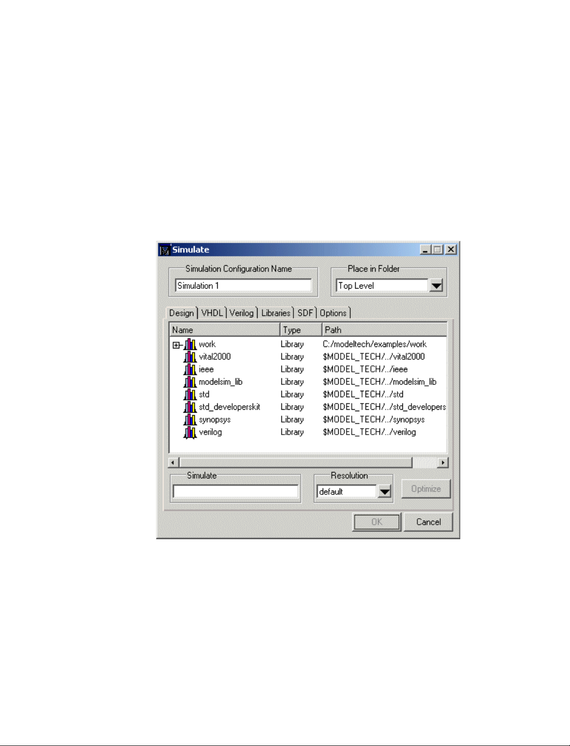
Creating a Simulation Configuration
A Simulation Configuration associates a design unit(s) and its simulation options. For
example, say you routinely load a particular design and you have to specify the simulator
resolution, generics, and SDF timing files. Or dinarily you wou l d have to specify t hose
options each time you load the design. With a Simulation Configuration, you would specify
the design and those options and then save the configuration with a name (e.g., top_config).
The name is then listed in the Project tab and you can double-click it to load the design
along with its options.
To create a Simulation Configuration, follow these steps:
1 Select File > Add to Project > Simulation Configuration ( Main window) o r select it
from the context menu in the Project tab.
ModelSim User’s Manual
2 Specify a name in the Simulation Configuration Name field.
3 Specify the folder in which you want to place the configuration (see Organi zing projects
with folders
4 Select one or more design unit(s) and click Add.
(UM-32)).
Page 31

Creating a Simulation Configu rat io n UM-31
Use the other tabs in the dialog to specify any required simulation options. All of the
5
options in t his dialog are described under "Simulating with the graphic interface"
.
245)
Click OK and the simulation configuration is added to the Project tab.
(UM-
Double-click the object to load it.
ModelSim User’s Manual
Page 32

UM-32 2 - Projects
Organizing projects with folders
Adding a folder
The more files you add to a project, the harder it can be to locate the item you need. You
can add "folders" to the project to organize your files. These folders are akin to directo ries
in that you can have multiple levels of folders and sub-folders. However, no actual
directories are created via the file system–the folders are present only within the project
file.
To add a folder to your project, select File > Add to Project > Folder.
Specify the Folder Name, the location for the folder, and click OK. The folder will be
displayed in the Project tab.
ModelSim User’s Manual
Page 33

Organizing projects with folders UM-33
You use the folders when you add new objects to the project. For example, when you add
a file, you can select which folder to place it in.
If you want to move a file into a folder later on, you can do so using the Properties dialog
for the file (right-click on the file and select Properties from the context menu).
ModelSim User’s Manual
Page 34

UM-34 2 - Projects
Setting compiler options
The VHDL and Verilog compilers (vcom and vlog, respectively) have numerous options
that affect how a design is compiled and subsequently simulated. You can customize the
settings on individual files or a group of files.
Important: Any changes you make to the compile properties outside of the project,
whether from the command line, the GUI, or the modelsim.ini file, will not affect the
properties of files already in the project.
To customize specific files, select the file(s) in the Project tab, right click on the file names,
and select Properties. The resulting dialog varies depending on the number and type of
files you have selected. If you select a single VHDL or Verilog file, you’ll see the General
tab and the VHDL or Verilog tab, respectively. On the General tab, you’ll see file properties
such as Type, Location, and Size. If you select multiple files, the file properties on the
General tab are not listed. Finally, if you select both a VHDL file and a Verilog file, you’ll
see all three tabs but no file information on the General tab.
ModelSim User’s Manual
The General tab includes these options:
• Do Not Compile
Determines whether the file is excluded from the compile.
• Compile to library
Specifies to which library you want to compile the file; defaults to the working library.
• Place in Folder
Specifies the folder in which to place the selected file(s). See "Organizing projects with
folders"
• File Properties
A variety of information about the selected file (e.g, type, size, path). Displays only if a
single file is selected in the Project tab.
The definitions of the options on the VHDL and Verilog tabs can be found in the section
"Setting default compile options"
(UM-32) for details on folders.
(UM-240).
Page 35

Accessing projects from the command line UM-35
When setting options on a group of files, keep in mind the following:
• If two or more files have different settings for the same option, the checkbox in the dialog
will be "grayed out." If you change the option, you cannot change it back to a "multi- state
setting" without cancelling out of the dialog. Once you click OK, ModelSim will set the
option the same for all selected files.
• If you select a combination of VHDL and Verilog files, the options you set on the VHDL
and Verilog tabs apply only to those file types.
Accessing projects from the command line
Generally, projects are used from within the ModelSim GUI. However, standalone tools
will use the project file if they are invoked in the project's root directory. If you want to
invoke outside the project directory, set the MODELSIM environment variable with the
path to the project file (<Project_Root_Dir>/<Project_Name>.mpf).
You can also use the project command
common operations on new projects. The command is to be used outside of a simulation
session.
(CR-104) from the command line to perform
ModelSim User’s Manual
Page 36

UM-36
ModelSim User’s Manual
Page 37

3 - Design libraries
Chapter contents
Design library contents. . . . . . . . . . . . . . UM-38
Design unit information . . . . . . . . . . . . UM-38
Archives . . . . . . . . . . . . . . . . UM-38
Design library types . . . . . . . . . . . . . . UM-39
Working with design libraries . . . . . . . . . . . . UM-40
Creating a library . . . . . . . . . . . . . . UM-40
Managing library contents . . . . . . . . . . . UM-41
Assigning a logical name to a design library . . . . . . . UM-43
Moving a library . . . . . . . . . . . . . . UM-44
Specifying the resource libraries . . . . . . . . . . . UM-45
VHDL resource libraries . . . . . . . . . . . . UM-45
Predefined libraries . . . . . . . . . . . . . UM-46
Alternate IEEE libraries supplied . . . . . . . . . . UM-46
Regenerating your design libraries . . . . . . . . . UM-47
UM-37
Importing FPGA libraries . . . . . . . . . . . . . UM-48
VHDL contains libraries, which are objects that contain compiled design units; libraries
are given names so they may be referenced. Verilog designs simulated with in ModelSim
are compiled into libraries as well.
ModelSim User’s Manual
Page 38

UM-38 3 - Design libraries
Design library contents
Design unit information
A design library is a directory or archive that serves as a repository for compiled design
units. The design units contained in a design library consist of VHDL entities, packages,
architectures, and configurations; and Verilog modules and UDPs (user-defined
primitives). The design units are classified as follows:
• Primary design units
Consist of entities, package declarations, configuration declarations, modules, and
UDPs. Primary design units within a given library must have unique names.
• Secondary design units
Consist of architecture bodies and package bodies. Secondary design units are associated
with a primary design unit. Architectures by the same name can exist if they are
associated with different entities.
The information stored for each design unit in a design library is:
• retargetable, executable code
Archives
• debugging information
• dependency information
By default design libraries are stored in a director y stru cture with a sub-dir ectory fo r each
design unit in the library. Alternatively, you can configure a design library to use archives.
In this case each design unit is stored in its own archive file. To create an archive, use the
-archive argument to the vlib command
Generally you would do this only in the rare case that you hit the reference count limit on
I-nodes due to the ".." entries in the lower-level directories. An example of an error message
that is produced when this limit is hit is:
mkdir: cannot create directory ‘65534’: Too many links
Archives may also have limited value to customers seeking disk space savings.
Note that GMAKE won’t work with these archives on the IBM platform.
(CR-180).
ModelSim User’s Manual
Page 39

Design library types
There are two kinds of design libraries: working libr aries and resource lib raries. A working
library is the library into which a design unit is placed after compilation. A resource library
contains design units that can be referenced within the design unit being compiled. Only
one library can be the working library; in contrast, any number of libraries (including the
working li brary itself) ca n be resource libraries during a compilation.
The library named work has special attributes within ModelSim; it is predefined in the
compiler and need not be declared explicitly (i.e. library work). It is also the library name
used by the compiler as the default destination of compiled design units. In other words the
work library is the working library. In all other aspects it is the same as any other library.
Design library types UM-39
ModelSim User’s Manual
Page 40

UM-40 3 - Design libraries
Working with design libraries
Creating a library
The implementation of a design library is not defined within standard VHDL or Verilog.
Within ModelSim design libraries are implemented as directories and can have any legal
name allowed by the operating system, with one exception; extended identifiers are not
supported for library names.
When you create a project (see "Getting started with projects" (UM-20)), ModelSim
automatically creates a working design library. If you don’t create a project, you need to
create a working design library bef ore yo u run the compiler. This can be done from either
the command line or from the ModelSim graphic interface.
From the ModelSim prompt or a DOS prompt, use this vlib command
vlib <directory_pathname>
To create a new library with the ModelSim graphic interface, select File > New > Library
(Main window).
The Create a New Library dialog box includes these options:
(CR-180):
ModelSim User’s Manual
• Create a new library and a logical mapping to it
Type the new library name into the Library Name field. This creates a library subdirectory in your current working directory, initially mapped to itself. Once created, the
mapped library is easily remapped to a different library.
• Create a map to an existing library
Type the new library name into the Library Name field, then type into the Library
Maps to field or Browse to select a library name for the mapping.
• Library Name
Type the logical name of the new library into this field.
Page 41

• Library Physical Name
Type the physical name of the new library into this field. ModelSim will create a
directory with this name.
• Library Maps to
Type or Browse for a mapping for the specified library. This field is visible and can be
changed only when the Create a map to an ex isting library opti on is selected.
When you cli ck OK, ModelSim creates the specified library directory and writes a
specially-formatted file named _info into that directory. The _info file must remain in the
directory to distinguish it as a ModelSim library.
The new map entry is written to the modelsim.ini file in the [Library] section. See
"[Library] library path variable s"
Note: Remember that a design library is a special kind of directory; the only way to
create a library is to use the ModelSim GUI or the vlib command
libraries using DOS or Windows commands.
Managing library contents
Working with design libraries UM-41
(UM-341) for more information.
(CR-180). Do not create
Library contents can be viewed, deleted, recompiled, edited and so on using either the
graphic interface or command line.
The Library tab in the Main window workspace provides access to design units
(configurations, modules, packages, entities, and architectures) in a library. The listing is
organized hierarchically, and the unit types are identified both by icon (entity (E), module
(M), and so forth) and the Type column.
ModelSim User’s Manual
Page 42
UM-42 3 - Design libraries
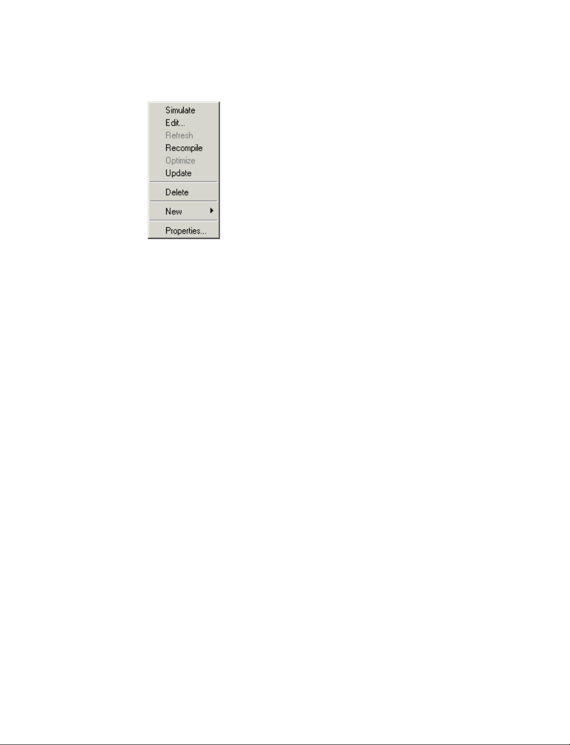
The Library tab has a context menu that you access by clicking your right mo use button in
the Library tab.
The context menu includes the following commands:
• Simulate
Loads the selected design unit and opens structure and Files tabs in the workspace.
Related command line command is vsim
(CR-189).
• Edit
Opens the selected design unit in the Source window, or if a library is selected, opens the
Edit Library Mapping dialog (see "Library mappings with the GUI"
(UM-43)).
• Refresh
Rebuilds the library image of the selected library without using source code. Related
command line command is vcom
(CR-145) or with the -refresh argument.
• Recompile
Recompiles the selected design unit. Related command line command is vcom
(CR-145)
or .
• Update
Updates the display of available libraries and design units.
• Delete
Deletes the selected design unit. Related command line command is vdel
(CR-151).
Deleting a package, configuration, or entity will remove the design unit from the library.
If you delete an entity that has one or more architectures, the entity and all its associated
architectures will be deleted.
You can also delete an architecture without deleting its associated entity. Expand the
entity, right-click the desired architecture name, and select Delete. You are prompted for
confirmation before any design unit is actually deleted.
• New
Create a new library.
ModelSim User’s Manual
• Properties
Displays various properties (e.g., Name, Type, Source, etc.) of the selected design unit
or library.
Page 43

Assigning a logical name to a design library
VHDL uses logical library names that can be mapped to ModelSim library directories. By
default, ModelSim can find libraries in your current directory (assuming they have the right
name), but for it to find libraries located elsewhere, you need to map a logical library name
to the pathname of the library.
You can use the GUI, a command, or a pro j ect to assign a log ical name to a d esign library.
Library mappings with the GUI
To associate a logical name with a library, select the library in the workspace, right-click
and select Edit from the context menu. This brings up a dialog box that allows you to edit
the mapping.
Working with design libraries UM-43
The dialog box includes these options:
• Library Mapping N ame
The logical name of the library.
• Library Pathname
The pathname to the library.
Library mapping from the command line
You can issue a command to set the mapping between a logical library name and a
directory; its form is:
vmap <logical_name> <directory_pathname>
You may invoke this command from either a DOS prompt or from the command line within
ModelSim.
When you use vmap
(CR-188) this way you are modifying the modelsim.ini file. You can
also modify modelsim.ini manually by adding a mapping li n e. To do this, use a text editor
and add a line under the [Library] section heading using the syntax:
<logical_name> = <directory_pathname>
ModelSim User’s Manual
Page 44

UM-44 3 - Design libraries
More than one logical name can b e mapped to a single directo ry. For examp le, suppose th e
modelsim.ini file in the current working directory contains following lines:
[Library]
work = /usr/rick/design
my_asic = /usr/rick/design
This would allow you to use either the logical name work or my_asic in a library or use
clause to refer to the same design library.
Moving a library
The vmap command
(CR-188) can also be used to display the mapping of a logical library
name to a directory. To do this, enter the shortened form of the command:
vmap <logical_name>
Library search rules
The system searches for the mapping of a logical name in the following order:
• First the system looks for a modelsim.ini file.
• If the system doesn’t find a modelsim.ini file, or if the specified logical name does not
exist in the modelsim.ini file, the system searches the current working directory for a
subdirectory that matches the logical name.
An error is generated by the compiler if you specify a logical name that does not resolve to
an existing directory.
Individual design units in a design library cannot be moved. An entire design library can
be moved, however, by using standard operating system commands for moving a directory
or an archive.
ModelSim User’s Manual
Page 45

Specifying the resource libraries
Verilog resource libraries
ModelSim supports and encourages separate compilation of distinct portions of a Verilog
design. The vlog
specified library. The library thus contains pre-comp iled modules and UDPs that are
referenced by the simulator as it loads the design. See "Library usage"
Important: Resource libraries are specified differently for Verilog and VHDL. For
Verilog you use either the -L or -Lf argument to vlog
VHDL resource libraries
Within a VHDL source file, you use the VHDL library clause to specify logical names of
one or more resource libraries to be r eferenc ed in the subsequent design unit. Th e scope of
a library clause includes the text region that starts immediately after the library clause an d
extends to the end of the declarative region of the a ssociated design unit. It does not extend
to the next design unit in the file.
(CR-181) compiler is used to compile one or more source files into a
Specifying the resource libraries UM-45
(UM-72).
(CR-181).
Note that the library clause is not used to specify the working library into which the design
unit is placed after compilation; the vcom command
to the current working library. By default, this is the library named work. To change the
current working library, you can use vcom -work and specify the name of the desired target
library.
Default binding rules
A common question related to resource libraries is how ModelSim handles default binding
for components. ModelSim addresses default binding at compile time. When look ing f or
an entity to bind with, ModelSim searches the currently visible libraries for an entity with
the same name as the component. ModelSim does this because IEEE 1076-1987 contained
a flaw that made it almost impossible for an entity to be directly visible if it had the same
name as the component. In short, if a componen t was declared in an arch itecture, any likenamed entity above that declaration would be hidden because component/entity names
cannot be overloaded. As a result we implemented the following rules for determining
default binding:
• If a directly visible entity has the same name as the component, use it.
• If the component is declared in a package, search the library that contained the package
for an entity with the same name.
• Search the work library.
• Search all other libraries that are currently visible by means of the library clause.
(CR-145) adds compiled design units
ModelSim User’s Manual
Page 46

UM-46 3 - Design libraries
Predefined libraries
In IEEE 1076-1993, the flaw was partially fixed in that the name look-up for the default
entity ignores component declarations. However, you could still encounter problems.
Consider the case where you declare a component C in a package P, library L contains an
entity C, and you have the following lines of code:
library L;
use L.P.all; -- Makes component C visible
use L.all; -- Because L.C exists and entity and component cannot be
overloaded, neither L.C nor L.P.C are directly visible.
In this case you couldn’t have the statement:
U1: C PORT MAP ( p1 => ...);
Instead, you need to have:
U1: P.C PORT MAP ( p1 => ...);
Because the default binding rules in IEEE 1076 contain these flaws, different simulators
implement default binding in different ways.
Certain resource libraries are predefined in standard VHDL. The library named std
contains the packages standard and textio, which should not be modi fied. The contents of
these packages and other aspects o f the p redefined langua ge environmen t are documented
in the IEEE Standard VHDL Language Reference Manua l, Std 1076- 1987 and ANSI /IEEE
Std 1076-1993. See also, "Using the TextIO package"
(UM-55).
A VHDL use clause can be specified to select particular declarations in a library or package
that are to be visible within a design unit during compilation. A use clause references the
compiled version of the package—not the source.
By default, every VHDL design unit is assumed to contain the following declarations:
LIBRARY std, work;
USE std.standard.all
To specify that all declarations in a library or pack age can be r eferenced, a dd the suffix .all
to the library/package name. For example, the use clause above specifies that all
declarations in the package standard in the design library named std are to be visible to the
VHDL design file in which the use clause is placed. Other libraries or packages are not
visible unless they are explicitly specified using a library or use clause.
Another predefined library is work, the library where a design unit is stored after it is
compiled as described earlier. There is no limit to the number of libraries that can be
referenced, but only one library is modified during compilation.
Alternate IEEE libraries supplied
The installation directory may contain two or more versions of the IEEE library:
• ieeepure
Contains only IEEE approved std_logic_1164 packages (accelerated for ModelSim).
ModelSim User’s Manual
Page 47

• ieee
Contains precompiled Synopsys and IEEE arithmetic packages which have been
accelerated by Model Technology including math_complex, math_real, numeric_bit,
numeric_std, std_logic_1164, std_logic_misc, std_logic_textio, std_logic_ ari th,
std_logic_signed, std_logic_unsigned, vital_primiti ves , and vital_timing.
You can select which library to use by changing the mapping in the modelsim.ini file. The
modelsim.ini file in the installation directory defaults to the ieee library.
Regenerating your design libraries
Dependin g on your current ModelSim version, you may need to regenerate your design
libraries before running a simulation. Check the installation README file to see if your
libraries require an update. You can regenerate your design libraries using the Refresh
command from the Library tab context menu (see "Managing library conten ts"
by using the -refresh argument to vcom
From the command line, you would use vcom with the -refresh option to update VHDL
design units in a lib rary , and vlog with the -refresh option to update Verilog design units.
By default, the work library is updated; use -work <library> to update a different library.
For example, if you have a library named mylib that contains both VHDL and Verilog
design units:
vcom -work mylib -refresh
vlog -work mylib -refresh
Specifying the resource libraries UM-47
(UM-41)), or
(CR-145) and vlog (CR-181).
An important feature of -refresh is that it rebuilds the library image without using source
code. This means that models delivered as compiled libraries without source code can be
rebuilt for a specific release of ModelSim (4.6 and later only). In general, this works for
moving forwards or backward s on a release. Movin g backwards on a release may not work
if the models used compiler switches or directives (Verilog only) that do not exist in the
older release.
Note: You don't need to regenerate the std, ieee, vital22b, and verilog libraries. Also, you
cannot use the -refresh option to update libraries that were built before the 4.6 release.
ModelSim User’s Manual
Page 48

UM-48 3 - Design libraries
Importing FPGA libraries
ModelSim includes an import wizard for referencing and using vendor FPGA libraries. The
wizard scans for and enforces dependencies in the libraries and determines the correct
mappings and target directories.
Important: The FPGA libraries you import must be pre-compiled. Most FPGA vendors
supply pre-compiled libraries configured for use with ModelSim.
To import an FPGA library, select File > Import > Library (Main window).
ModelSim User’s Manual
Follow the instructions in the wizard to complete the import.
Page 49

4 - VHDL simulation
Chapter contents
Compiling VHDL designs . . . . . . . . . . . . . UM-50
Creating a design library . . . . . . . . . . . . UM-50
Invoking the VHDL compiler. . . . . . . . . . . UM-50
Dependency checking. . . . . . . . . . . . . UM-50
Range and index checking . . . . . . . . . . . UM-50
Simulating VHDL designs . . . . . . . . . . . . . UM-52
Simulator resolution limit . . . . . . . . . . . . UM-52
Delta delays . . . . . . . . . . . . . . . UM-53
Using the TextIO package . . . . . . . . . . . . . UM-55
Syntax for file declaration. . . . . . . . . . . . UM-55
Using STD_INPUT and STD_OUTPUT within ModelSim . . . UM-56
TextIO implementation issues . . . . . . . . . . . . UM-57
Writing strings and aggregates . . . . . . . . . . UM-57
Reading and writing hexadecimal numbers . . . . . . . UM-58
Dangling pointers . . . . . . . . . . . . . . UM-58
The ENDLINE function . . . . . . . . . . . . UM-58
The ENDFILE function . . . . . . . . . . . . UM-58
Using alternative input/output files . . . . . . . . . UM-59
Providing st imulus . . . . . . . . . . . . . UM-59
UM-49
VITAL specification and source code . . . . . . . . . . UM-60
VITAL packages . . . . . . . . . . . . . . . UM-60
ModelSim VITAL compliance. . . . . . . . . . . . UM-60
VITAL compliance checking . . . . . . . . . . . UM-60
Compiling and simulating with accelerated VITAL packages . . UM-61
Compiling and simulating with accelerated VITAL packages . . . UM-61
Util package . . . . . . . . . . . . . . . . UM-62
get_resolution . . . . . . . . . . . . . . . UM-62
init_signal_driver() . . . . . . . . . . . . . UM-63
init_signal_spy() . . . . . . . . . . . . . . UM-63
signal_force() . . . . . . . . . . . . . . . UM-63
signal_release() . . . . . . . . . . . . . . UM-63
to_real() . . . . . . . . . . . . . . . . UM-64
to_time() . . . . . . . . . . . . . . . . UM-65
This chapter provides an overview of compilation and simulation for VHDL; using the
TextIO package with ModelSim; ModelSim’s implementation of the VITAL (VHDL
Initiative Towards ASIC Libraries) specification for ASIC modeling; and docu mentation
on ModelSim’s special built-in utilities package.
The TextIO package is defined within the VHDL L an gua ge Ref erence Manuals, IEEE St d
1076-1987 and IEEE Std 1076-1993; it allows human-readable text input from a declared
source within a VHDL file during simulation.
ModelSim User’s Manual
Page 50

UM-50 4 - VHDL simulation
Compiling VHDL designs
Creating a design library
Before you can compile your design, you must create a library in which to store the
compilation results. Use vlib
vlib work
(CR-180) to create a new library. For example:
This creates a library named work. By default, compilation results are stored in the work
library.
Note: The work library is actually a subdirectory named work. This subdirectory
contains a special file named _info. Do not create libraries using MS Windows or DOS
commands – always use the v lib command
(CR-180).
See "Design libraries"
Invoking the VHDL compiler
ModelSim compiles one or more VHDL design units with a single invocation of vcom (CR-
, the VHDL compiler. The design units are compiled in the order that they appear on
145)
the command line. For VHDL, the order of compilation is important – you must compile
any entities or configurations before an architecture that references them.
You can simulate a design containing units written with both the 1076 -1987 and 1076
-1993 versions of VHDL. To do so you will need to compile units from each VHDL version
separately. The vcom
by default; use the -93 option with vcom
1076 -1993. You can also change the default by modifying the modelsim.ini file (see
"Preference variables located in INI files"
Dependency checking
Dependent design units must be reanalyzed when the design units they depend on are
changed in the library. vcom
have changed. For example, if you keep an entity and its architectures in the same source
file and you modify only an architecture and recompile the source file, the entity
compilation results will remain unchanged and you will not have to recompile design units
that depend on the entity.
(UM-37) for additional information on working with libraries.
(CR-145) command compiles units written with version 1076 -1987
(CR-145) to compile units written with version
(UM-341) for more information).
(CR-145) determines whether or not the compilation results
Range and index checking
ModelSim User’s Manual
A range check verifies that a scalar value defined with a range subtype is always assigned
a value within its range. An index check verifies that whenever an array subscript
expression is evaluated, the subscript will be within the array's range.
Range and index checks are perfor med by default when you compi le your desi gn. You can
disable range checks (potentially offering a performance advantage) and index checks
using arguments to the vcom
(CR-145) command. Or, you can use the NoRangeCheck and
NoIndexCheck variables in the modelsim.ini file to specify whether or not they are
performed. See "Preference variables located in INI files"
(UM-341).
Page 51

Compiling VHDL designs UM-51
Range checks in ModelSim are slightly more restrictive than those specified by the VHDL
LRM. ModelSim requires any assignment to a signal to also be in range whereas the LRM
requires only that range checks be d one whenever a sig nal is updated. Most assignments to
signals update the signal anyway, and the more restrictive requirement allows ModelSim
to generate better error messages.
ModelSim User’s Manual
Page 52

UM-52 4 - VHDL simulation
Simulating VHDL designs
After compiling the design units, you can simulate your designs with vsim (CR-189). This
section discusses simulation from the Windows/DOScommand line. You can also use a
project to simulate (see "Getting started with projects"
(see "Simulating with the graphic interface"
For VHDL invoke vsim
(CR-189) with the name of the configuration, or entity/ architecture
(UM-245)).
(UM-20)) or the Simulate dialog box
pair. Note that if you specify a configuration you may not specify an architecture.
This example invokes vsim
vsim my_asic structure
vsim (CR-189) is capable of annotating a design using VITAL compliant models with timing
data from an SDF file. You can specify the min:typ:max delay by invoking vsim with the
-sdfmin, -sdftyp and -sdfmax options. Using the SDF file f1.sdf in the current work
directory, the following invocation of vsim annotates maximum timing values for the
design unit my_asic:
vsim -sdfmax /my_asic=f1.sdf my_asic
By default, the timing checks within VITAL models are enabled. They can be disabled with
the +notimingchecks option. For example:
vsim +notimingchecks topmod
Simulator resolution limit
The simulator internally represents time as a 64-bit integer in units equivalent to the
smallest unit of simulation time, also known as the simulator resolution limit. The default
resolution limit is set to the value specified by the Resolution
modelsim.ini file. You can view the current resolution by invoking the report command
(CR-109) with the simulator state option .
Overriding the resolution
You can override ModelSim’s default resolution by specifying the -t option on the
command line or by selecting a different Simula tor Resolution in the Simulate dialog box.
Available resolutions are: 1x, 10x or 100x of fs, ps, ns, us, ms, or sec.
(CR-189) on the entity my_asic and the architecture structure:
(UM-347) variable in the
ModelSim User’s Manual
For example this command chooses 10 ps resolution:
vsim -t 10ps topmod
Clearly you need to be careful when doing this type of operation. If the resolution set by -t
is larger than a delay value in your design, the delay values in that design unit are rounded
to the next multiple of the resolution. In the example above, a delay of 4 ps would be
rounded to 0 ps.
Choosing the resolution
You should choose the coarsest resolution limit possible that does not result in undesired
rounding of your delays. The time precision should not be unnecessarily small because it
will limit the maximum simulation time limit, and it will degrade performance in some
cases.
Page 53

Delta delays
Simulating VHDL designs UM-53
Event-based simulators such as ModelSim may process many events at a given s imulation
time. Multiple signals may need updating, statements that are sensitive to these signa ls
must be executed, and any new events that result from these statements must then be
queued and executed as well. The steps taken to evaluate the design without advancing
simulation time are referred to as "delta times" or just "deltas."
The diagram below represents the process for VHDL designs. This process continues until
the end of simulation time.
Execute
concurrent
statements at
Advance
delta time
current time
Advance
simulation
time
Any transactions
No
to process?
Any events to
Yes
No
process?
Yes
Execute concurrent
statements that are
sensitive to events
This mechanism in event-based simulators may cause unexpected results. Consider the
following code snippet:
.
.
.
clk2 <= clk;
process (rst, clk)
begin
if(rst = ’0’)then
s0 <= ’0’;
elsif(clk’event and clk=’1’) then
s0 <= inp;
end if;
end process;
process (rst, clk2)
begin
if(rst = ’0’)then
ModelSim User’s Manual
Page 54

UM-54 4 - VHDL simulation
s1 <= ’0’;
elsif(clk2’event and clk2=’1’) then
s1 <= s0;
end if;
end process;
.
.
.
In this example you have two synchronous processes, one t r ig gered with clk an d the o ther
with clk2. To your surprise, the signals change in the clk2 process on the same edge as they
are set in the clk process. As a result, the value of inp appears at s1 rather than s0. What is
going on?
Here is what’s happing. During simulation an event on clk occurs (from the testbench).
From this event ModelSim performs the "clk2 <= clk" assignment and the process which
is sensitive to clk. Before advancing the simulation time, ModelSim finds that the process
sensitive to clk2 can also be run. Since there are no delays present, the effect is that the
value of inp appears at s1 in the same simulation cycle.
In order to get the expected results, you must do one of the following:
1 insert delay at every output
2 make certain to use the same clock
3 insert a delta delay
To insert a delta delay, you would modify the code like this:
process (rst, clk)
begin
if(rst = ’0’)then
s0 <= ’0’;
elsif(clk’event and clk=’1’) then
s0 <= inp;
s0_delayed <= s0;
end if;
end process;
process (rst, clk2)
begin
if(rst = ’0’)then
s1 <= ’0’;
elsif(clk2’event and clk2=’1’) then
s1 <= s0_delayed;
end if;
end process;
The best way to debug delta delay problems is observe your signals in the List window.
There you can see how values change at each delta time.
ModelSim User’s Manual
Page 55

Using the TextIO package
To access the routines in TextIO, include the following statement in your VHDL source
code:
USE std.textio.all;
A simple example using the package TextIO is:
USE std.textio.all;
ENTITY simple_textio IS
END;
ARCHITECTURE simple_behavior OF simple_textio IS
BEGIN
PROCESS
VARIABLE i: INTEGER:= 42;
VARIABLE LLL: LINE;
BEGIN
WRITE (LLL, i);
WRITELINE (OUTPUT, LLL);
WAIT;
END PROCESS;
END simple_behavior;
Using the TextIO package UM-55
Syntax for file declaration
The VHDL’87 syntax for a file declaration is:
file identifier : subtype_indication is [ mode ] file_logical_name ;
where "file_logical_name" must be a string expression.
The VHDL’93 syntax for a file declaration is:
file identifier_list : subtype_indication [ file_open_information ] ;
where "file_open_information" is:
[open file_open_kind_expression] is file_logical_name
You can specify a full or relative path as the file_logical_name; for example (VHDL’87):
Normally if a file is declared within an architecture, process, or package, the file is opened
when you start the simulator and is closed when you exit from it. If a file is declared in a
subprogram, the file is opened when the subprogram is called and closed when execution
RETURNs from the subprogram. Alternatively, the opening of files can be delayed until
the first read or write by setting the DelayFileOpen variable in the modelsim.ini file. Also,
the number of concurrently open files can be controlled by the ConcurrentFileLimit
variable. These variables help you manage a large number of files during simulation. See
Appendix A - ModelSim variables for more details.
ModelSim User’s Manual
Page 56

UM-56 4 - VHDL simulation
Using STD_INPUT and STD_OUTPUT within ModelSim
The standard VHDL’87 TextIO package contains the following file declarations:
file input: TEXT is in "STD_INPUT";
file output: TEXT is out "STD_OUTPUT";
The standard VHDL’93 TextIO package contains these file declarations:
file input: TEXT open read_mode is "STD_INPUT";
file output: TEXT open write_mode is "STD_OUTPUT";
STD_INPUT is a file_logical_name that refers to characters that are entered interactively
from the keyboard, and STD_OUTPUT refers to text that is displayed on the screen.
In ModelSim, reading from the STD_INPUT file allows you to enter text into the current
buffer from a prompt in the Main window. The lines written to the STD_OUTPUT file
appear in the Main window transcript.
ModelSim User’s Manual
Page 57

TextIO implementation issues
Writing strings and aggregates
A common error in VHDL source code occurs when a call to a WRITE procedur e does not
specify whether the argument is of type STRING or BIT_VECTOR. For example, the
VHDL procedure:
WRITE (L, "hello");
will cause the following error:
ERROR: Subprogram "WRITE" is ambiguous.
In the TextIO package, the WRITE procedure is overloaded for the types STRING and
BIT_VECTOR. These lines are reproduced here:
procedure WRITE(L: inout LINE; VALUE: in BIT_VECTOR;
JUSTIFIED: in SIDE:= RIGHT; FIELD: in WIDTH := 0);
procedure WRITE(L: inout LINE; VALUE: in STRING;
JUSTIFIED: in SIDE:= RIGHT; FIELD: in WIDTH := 0);
TextIO implementation issues UM-57
The error occurs because the argument "hello" could be interpreted as a string or a bit
vector, but the compiler is not allowed to determine the argument type until it knows which
function is being called.
The following procedure call also generates an error:
WRITE (L, "010101");
This call is even more ambiguous, because the compiler could not determine, even if
allowed to, whether the argument "010101" should be interpreted as a string or a bit vector.
There are two possible solutions to this problem:
• Use a qualified expression to specify the type, as in:
WRITE (L, string’("hello"));
• Call a procedure that is not overloaded, as in:
WRITE_STRING (L, "hello");
The WRITE_STRING procedure simply defines the value to be a STRING and calls the
WRITE procedure, but it serves as a shell around the WRITE procedure that solves the
overloadin g problem. For further details, refer to the WRITE_STRING procedure in the
io_utils package, which is located in the file <install_dir>/modeltech/examples/
io_utils.vhd.
ModelSim User’s Manual
Page 58

UM-58 4 - VHDL simulation
Reading and writing hexadecimal numbers
Dangling pointers
The reading and writing of hexadecimal numbers is not specified in standard VHDL. The
Issues Screening and Analysis Committee of the VHDL Analysis and Standardization
Group (ISAC-VASG) has specified that the TextIO package reads and writes only decimal
numbers.
To expand this functionality, ModelSim supplies hexadecimal routines in the package
io_utils, which is located in the file <install_dir>/modeltech/examples/io_utils.vhd. To use
these routines, compile the io_utils package and then include the following use clauses in
your VHDL source code:
use std.textio.all;
use work.io_utils.all;
Dangling pointers are easily created when using the TextIO package, because
WRITELINE de-allocates the access type (pointer) that is passed to it. Following are
examples of good and bad VHDL coding styles:
Bad VHDL (because L1 and L2 both point to the same buffer):
READLINE (infile, L1); -- Read and allocate buffer
L2 := L1; -- Copy pointers
WRITELINE (outfile, L1); -- Deallocate buffer
Good VHDL (because L1 and L2 point to different buffers):
READLINE (infile, L1); -- Read and allocate buffer
L2 := new string’(L1.all); -- Copy contents
WRITELINE (outfile, L1); -- Deallocate buffer
The ENDLINE function
The ENDLINE function described in the IEEE Standard VHDL Language Reference
Manual, IEEE Std 1076-1987 contains invalid VHDL syntax and cannot be implemented
in VHDL. This is because access types must be passed as variables, but functions only
allow constant parameters.
Based on an ISAC-VASG recommendation the ENDLINE function has been removed
from the TextIO package. The following test may be substituted for this function:
(L = NULL) OR (L’LENGTH = 0)
The ENDFILE function
In the VHDL Language Reference Manuals, IEEE Std 1076 -1987 and IEEE Std 107 6-1993,
the ENDFILE function is listed as:
-- function ENDFILE (L: in TEXT) return BOOLEAN;
As you can see, this function is commented out of the standard TextIO package. This is
because the ENDFILE function is implicitly declared, so it can be used with files of any
type, not just files of type TEXT.
ModelSim User’s Manual
Page 59

Using alternative input/output files
You can use the TextIO package to read and write to your own files. To do this, just declare
an input or output file of type TEXT. For example, for an input file:
The VHDL’87 declaration is:
file myinput : TEXT is in "pathname.dat";
The VHDL’93 declaration is:
file myinput : TEXT open read_mode is "pathname.dat";
Then include the identifier for this file ("myinput" in this example) in the READLINE or
WRITELINE procedure call.
Providing stimulus
You can stimulate and test a design by reading vectors from a file, using them to drive
values onto signals, and testing the results. A VHDL test bench has been included with the
ModelSim install files as an example. Check for this file:
<install_dir>/modeltech/examples/stimulus.vhd
TextIO implementation issues UM-59
ModelSim User’s Manual
Page 60

UM-60 4 - VHDL simulation
VITAL specification and source code
VITAL packages
VITAL ASIC Modeling Specification
The IEEE 1076.4 VITAL ASIC Modeling Specification is available from the Institute of
Electrical and Electronics Engineers, Inc.:
IEEE Customer Service
445 Hoes Lane
Piscataway, NJ 08855-1331
Tel: (732) 981-0060
Fax: (732) 981-1721
home page: http://www.ieee.org
VITAL source code
The source code for VITAL packages is provided in the /<install_dir>/vhdl_src/vital22b,
/vital95, or /vital2000 directories.
VITAL 1995 accelerated packages are pre-compiled into the ieee library in the installation
directory. VITAL 2000 accelerated packages are pre-compiled into the vital2000 library.
If you need to use th e newe r library, you’ ll need to a dd a use clause to your VHDL code to
access the VITAL 2000 packages. For example:
LIBRARY vital2000;
USE vital2000.all
ModelSim VITAL compliance
A simulator is VITAL compliant if it implements the SDF mapping and if it co rrectly
simulates designs using the VITAL packages, as outlined in the VITAL Model
Development Specification. ModelSim is compliant with the IEEE 1076.4 VITAL ASIC
Modeling Specification. In addition, ModelSim accelerates the VITAL_Timing,
VITAL_Primitives, and VITAL_memory packages. The optimized procedures are
functionally equivalent to the IEEE 107 6.4 VITAL ASIC Modeling Specif ication (VITAL
1995 and 20 00).
VITAL compliance checking
If you are using VITAL 2.2b, you must turn off the compliance checking either by not
setting the attributes, or by invoking vcom
(CR-145) with the option -novitalcheck.
ModelSim User’s Manual
Page 61

Compiling and simulating with accelerated VITAL packages UM-61
Compiling and simulating with accelerated VITAL packages
vcom (CR-145) automatically recognizes that a VITAL function is being referenced from
the ieee library and generates code to call the optimized built-in routines.
Invoke with the -novital option if you do not want to use the built-in VITAL routines
(when debugging for instance). To exclude all VITAL functions, use -novital all:
vcom -novital all design.vhd
To exclude selected VITAL functions, use one or more -novital <fname> options:
vcom -novital VitalTimingCheck -novital VitalAND design.vhd
The -novital switch only affects calls to VITAL functions from the design units currently
being compiled. Pre-compiled design units referenced from the current design units will
still call the built-in functions unless they too are compiled with the -novital optio n.
ModelSim VITAL built-ins will be updated in step with new releases of the VITAL
packages.
ModelSim User’s Manual
Page 62

UM-62 4 - VHDL simulation
Util package
get_resolution
The util package, included in ModelSim versions 5.5 and later, serves as a container for
various VHDL utilities. The package is part of the modelsim_lib library which is located in
the modeltech tree and is mapped in the default modelsim.ini file.
To access the utilities in the package, you would add lines like the following to your VHDL
code:
library modelsim_lib;
use modelsim_lib.util.all;
get_resolution returns the current simulato r resolution as a real number. For example, 1
femtosecond corresponds to 1e-15.
Syntax
resval := get_resolution;
Returns
Name Type Description
resval real The simulator resolution represented as a real
Arguments
None
Related functions
to_real() (UM-64)
to_time() (UM-65)
Example
If the simulator resolution is set to 10ps, and you invoke the command:
resval := get_resolution;
the value returned to resval would be 1e-11.
ModelSim User’s Manual
Page 63

init_signal_driver()
The init_signal_driver() procedure drives the value of a VHDL signal or Verilog net onto
an existing VHDL signal or Verilog net. This allows you to drive signals or nets at any level
of the design hierarchy from within a VHDL architecture (e.g., a testbench).
Util package UM-63
init_signal_spy()
signal_force()
signal_release()
See init_signal_driver
(UM-271) in Chapter 8 - Signal Spy for complete details and syntax
on this procedure.
The init_signal_spy() utility mirrors the value of a VHDL signal or Verilog register/ net
onto an existing VHDL signal or Verilog register. This allows you to reference signals,
registers, or nets at any level of hierarchy from within a VHDL architecture (e.g., a
testbench).
See init_signal_spy
(UM-274) in Chapter 8 - Signal Spy for complete details and syntax on
this procedure.
The signal_force() procedure forces the value specified onto an existing VHDL signal or
Verilog register or net. This allows you to force signals, registers, or nets at any level of the
design hierarchy from within a VHDL architecture (e.g., a testbench). A signal_force works
the same as the force command
(CR-82) with the exception that you cannot issue a repeating
force.
See signal_force
(UM-276) in Chapter 8 - Signal Spy for complete details and syntax on this
procedure.
The signal_release() procedure releases any force that was applied to an existing VHDL
signal or Verilog register or net . This allows y ou to release signal s, registers, or nets at any
level of the design hierarchy from within a VHDL architecture (e.g., a testbench). A
signal_release works the same as the noforce command
See signal_release
(UM-278) in Chapter 8 - Signal Spy for complete details and syntax on
(CR-92).
this procedure.
ModelSim User’s Manual
Page 64

UM-64 4 - VHDL simulation
to_real()
to_real() converts the physical type time value into a real value with respect to the current
simulator resolution. The precision of the converted value is determ ined by the simulator
resolution. For example, if you were converting 1900 fs to a real and the simulator
resolution was ps, then the real value would be 2.0 (i.e., 2 ps).
Syntax
realval := to_real(timeval);
Returns
Name Type Description
realval real The time value represented as a real with
respect to the simulator resolution
Arguments
Name Type Description
timeval time The value of the physical type time
Related functions
get_resolution (UM-62)
to_time() (UM-65)
Example
If the simulator resolution is set to ps, and you enter the following fun ction:
realval := to_real(12.99 ns);
then the value returned to realval would be 12990.0. If you wanted the returned value to be
in units of nanoseconds (ns) i nstead, you would u se the get_resolution
(UM-62) function to
recalculate the value:
realval := 1e+9 * (to_real(12.99 ns)) * get_resolution();
If you wanted the returned value to be in units of femtoseconds (fs), you would enter the
function this way:
realval := 1e+15 * (to_real(12.99 ns)) * get_resolution();
ModelSim User’s Manual
Page 65

to_time()
Util package UM-65
to_time() converts a real value into a time value with respect to the current simulator
resolution. The precision of the converted value is determined by the simulator resolution.
For example, if you were converting 5.9 to a time and the simulator resolution was ps, then
the time value would be 6 ps.
Syntax
timeval := to_time(realval);
Returns
Name Type Description
timeval time The real value represented as a physical type
time with respect to the simulator resolution
Arguments
Name Type Description
realval real The value of the type real
Related functions
get_resolution (UM-62)
to_real() (UM-64)
Example
If the simulator resolution is set to ps, and you enter the following fun ction:
timeval := to_time(72.49);
then the value returned to timeval would be 72 ps.
ModelSim User’s Manual
Page 66

UM-66
ModelSim User’s Manual
Page 67

5 - Verilog simulation
Chapter contents
Compilation . . . . . . . . . . . . . . . . UM-69
Incremental compilation . . . . . . . . . . . . UM-70
Library usage . . . . . . . . . . . . . . . UM-72
Verilog-XL compatible compiler arguments . . . . . . . UM-73
Verilog-XL ‘uselib compiler directive . . . . . . . . UM-74
Simulation . . . . . . . . . . . . . . . . . UM-76
Invoking the simulator . . . . . . . . . . . . UM-76
Simulator resolution limit . . . . . . . . . . . . UM-77
Event ordering in Verilog designs . . . . . . . . . UM-79
Negative timing check limits . . . . . . . . . . . UM-83
Verilog-XL compatible simulator arguments . . . . . . . UM-86
Cell libraries . . . . . . . . . . . . . . . . UM-87
SDF timing annotation . . . . . . . . . . . . UM-87
Delay modes . . . . . . . . . . . . . . . UM-87
UM-67
System tasks . . . . . . . . . . . . . . . . UM-89
IEEE Std 1364 system tasks . . . . . . . . . . . UM-89
Verilog-XL compatible system tasks . . . . . . . . . UM-92
ModelSim Verilog system tasks . . . . . . . . . . UM-94
Compiler directives . . . . . . . . . . . . . . UM-95
IEEE Std 1364 compiler directives . . . . . . . . . UM-95
Verilog-XL compatible compiler directives . . . . . . . UM-96
Verilog PLI/VPI . . . . . . . . . . . . . . . UM-97
Registering PLI applications . . . . . . . . . . . UM-97
Registering VPI applications . . . . . . . . . . . UM-99
Compiling and linking PLI/VPI C applications . . . . . UM-101
Compiling and linking PLI/VPI C++ applications . . . . UM-102
Specifying the PLI/VPI file to load . . . . . . . . UM-103
PLI example . . . . . . . . . . . . . . UM-104
VPI example . . . . . . . . . . . . . . UM-105
The PLI callback reason argument . . . . . . . . UM-106
The sizetf callback function . . . . . . . . . . UM-107
PLI object handles. . . . . . . . . . . . . UM-107
Third party PLI applications . . . . . . . . . . UM-108
Support for VHDL objects . . . . . . . . . . UM-109
IEEE Std 1364 ACC routines . . . . . . . . . . UM-110
IEEE Std 1364 TF routines . . . . . . . . . . UM-111
Verilog-XL compatible routines . . . . . . . . . UM-113
64-bit support in the PLI . . . . . . . . . . . UM-113
PLI/VPI tracing . . . . . . . . . . . . . UM-113
Debugging PLI/VPI application code. . . . . . . . UM-115
ModelSim User’s Manual
Page 68

UM-68 5 - Verilog simulation
This chapter describes how to compile and simulate Verilog designs with ModelSim
Verilog. ModelSim Verilog implements the Verilog language as defined by the IEEE Std
1364, and it is recommended that you obtain this specification as a reference manual.
In addition to the functionality described in the IEEE Std 1364, ModelSim Verilog includes
the following features:
• Standard Delay Format (SDF) annotator compatible wi th many ASIC and FPGA vendor' s
• Value Change Dump (VCD) file extensions for ASIC vendor test tools
• Dynamic loading of PLI/VPI applications
• Compilation into retargetable, executable code
• Incremental design compilation
• Extensive support for mixing VHDL and Verilog in the same design (including SDF
• Graphic Interface that is common with ModelSim VHDL
• Extensions to provide compatibility with Verilog-XL
The following IEEE Std 1364 f unctionality is partially implemen ted in ModelSim Verilog:
Verilog libraries
annotation)
• Verilog Procedural Interface (VPI) (see /<install_dir>/modeltech/docs/technotes/
Verilog_VPI.note for details)
• Verilog 2001 (see /<install_dir>/modeltech/docs/technotes/vlog_2000.note for details)
Many of the examples in this chapter are shown from the command line. For compiling and
simulating within a project or ModelSim’s GUI see:
• Getting started with projects
(UM-20)
• Compiling with the graphic interface (UM-238)
• Simulating with the graphic interface (UM-245)
ModelSim User’s Manual
Page 69

Compilation
Compilation UM-69
Before you can simulate a Ve rilog design, you must first create a library and compile the
Verilog source code into that library. This section provides detailed information on
compiling Verilog designs. For information on creating a design library, see Chapter 3 -
Design libraries.
The ModelSim Verilog compiler, vlog, compiles Verilog source code into retargetable,
executable code, meaning that the library format is compatible across all supported
platforms a nd that you can simulate your design on any platform without having to
recompile your design specifically for that platform. As you compile your design, the
resulting object code for modules and UDPs is generated into a library. By default, the
compiler places results into the work library. You can s pecify an alternate library with the
-work argument. The following is a simple example of how to create a work library,
compile a design, and simulate it:
Contents of top.v:
module top;
initial $display("Hello world");
endmodule
Create the work library:
% vlib work
Compile the design:
% vlog top.v
-- Compiling module top
Top level modules:
top
View the contents of the work library (optional):
% vdir
MODULE top
Simulate the design:
% vsim -c top
# Loading work.top
VSIM 1> run -all
# Hello world
VSIM 2> quit
In this example, the simulator was run without the graphic interface by specifying the -c
argument. After the design was loaded, the simulator command run -all was entered,
meaning to simulate until there are no more simulator events. Finally, the quit command
was entered to exit the simulator. By default, a log of the simulation is written to the
transcript file in the current directory.
ModelSim User’s Manual
Page 70

UM-70 5 - Verilog simulation
Incremental compilation
By default, ModelSim Verilog supports incremental compilatio n of designs, thus saving
compilation time when you modify your design. Unlike other Verilog simulators, there is
no requirement that you compile the entire design in one invocation of the compiler .
You are not required to compile your design in any particular order because all module an d
UDP instantiations and external hierarchical references are resolved when the design is
loaded by the simulator. Incremental compilation is made possible by deferring these
bindings, and as a result some errors cannot be detected during compilation. Commonly,
these errors include: modules that were referenced but not compiled, incorrect port
connections, and incorrect hierarchical references.
The following example shows how a hierarchical design can be compiled in top-down
order:
Contents of top.v:
module top;
or2 or2_i (n1, a, b);
and2 and2_i (n2, n1, c);
endmodule
Contents of and2.v:
module and2(y, a, b);
output y;
input a, b;
and(y, a, b);
endmodule
Contents of or2.v:
module or2(y, a, b);
output y;
input a, b;
or(y, a, b);
endmodule
Compile the design in top down order (assumes work library already exists):
% vlog top.v
-- Compiling module top
Top level modules:
top
% vlog and2.v
-- Compiling module and2
Top level modules:
and2
% vlog or2.v
-- Compiling module or2
ModelSim User’s Manual
Top level modules:
or2
Note that the compiler lists each module as a top level module, although, ultimately, only
top is a top-level module. If a module is not referenced by another module compiled in the
same invocation of the compiler, then it is listed as a top level module. This is just an
Page 71

Compilation UM-71
informative message and can be ignored during incremental compilation. The message is
more useful when you compile an entire desi gn in one invocation of the compiler and need
to know the top-level module names for the simulator. For example,
% vlog top.v and2.v or2.v
-- Compiling module top
-- Compiling module and2
-- Compiling module or2
Top level modules:
top
The most efficient method of incremental compilation is to manually compile only the
modules that have changed. This is not always convenient, especially if your source files
have compiler directive interdependencies (such as macros). In this case, you may prefer to
always compile your entire design in one invocation of the compiler. If you specify the
-incr argument, the compiler will automatically determine which modules have changed
and generate code only for those modules. This is not as efficient as manual incremental
compilation because the compiler must scan all of the source code to determine which
modules must be compiled.
The following is an example of how to compile a design with automatic incremental
compilation:
% vlog -incr top.v and2.v or2.v
-- Compiling module top
-- Compiling module and2
-- Compiling module or2
Top level modules:
top
Now, suppose that you modify the functionality of the or2 module:
% vlog -incr top.v and2.v or2.v
-- Skipping module top
-- Skipping module and2
-- Compiling module or2
Top level modules:
top
The compiler informs you that it skipped the modules top and and2, and compiled or2.
Automatic incremental compilation is intelligent about when to compile a module. For
example, changing a comment in your source code does not result in a recompile; however,
changing the compiler command line arguments results in a recompile of all modules.
Note: Changes to your source code that do not change functionality but that do affect
source code line numbers (such as adding a comment line) will cause all affected
modules to be recompiled. This happens becaus e debug information must be kept curren t
so that ModelSim can trace back to the correct areas of the source code.
ModelSim User’s Manual
Page 72

UM-72 5 - Verilog simulation
Library usage
All modules and UDPs in a Verilog design must be compiled into one or more libraries.
One library is usually sufficient for a simple design, but you may want to organize your
modules into variou s libraries for a co mplex design. If your des ign uses different mod ule s
having the same name, then you are required to put those modules in different libraries
because design unit names must be unique within a library.
The following is an example of how you may organize your ASIC cells into one library and
the rest of your design into another:
% vlib work
% vlib asiclib
% vlog -work asiclib and2.v or2.v
-- Compiling module and2
-- Compiling module or2
Top level modules:
and2
or2
% vlog top.v
-- Compiling module top
Top level modules:
top
Note that the first compilation uses the -work asiclib argument to instruct the compiler to
place the results in the asiclib library rather than the default work library.
Since instantiation bindings are not determined at compile time, you must instruct the
simulator to search your libraries when loading the design. The top-level modules are
loaded from the library named work unless you prefix the modules with the <library>.
option. All other Verilog instantiations are resolved in the following order:
• Search libraries specified with -Lf arguments in the order they appear on the command
line.
• Search the library specified in the "Verilog-XL `uselib compiler directive"
(UM-74).
• Search libraries specified with -L arguments in the order they appear on the command
line.
• Search the work library.
• Search the library explicitly named in the special escaped identifier instance name.
The work library is not necessarily a library named work—rather, the work library refers
to the library containing the module that instantiates the module or UDP that is currently
being searched for. This definition is useful if you have hierarchical modules organized into
separate libraries and if sub-module names overlap among the libraries. In this situation you
want the modules to search for their sub-modules in the work library first. This is
accomplished by specifying -L work first in the list of search libraries.
For example, assume you have a top-level module top that instantiates module modA from
library libA and module modB from library libB. Furthermore, modA and modB both
instantiate modules named cellA, but the definition of cellA compiled into libA is different
from that compiled into libB. In this case, it is insufficient to just specify -L libA - L libB
as the search libraries because instantiations o f cellA from modB resolve to the libA version
of cellA. The appropriate search library arguments are -L work -L libA -L libB.
ModelSim User’s Manual
Page 73

Verilog-XL compatible compiler arguments
The compiler arguments listed below are equivalent to Verilog-XL arguments and may
ease the porting of a design to ModelSim. See the vlog command
of each argument.
+define+<macro_name>[=<macro_text>]
+delay_mode_distributed
+delay_mode_path
+delay_mode_unit
+delay_mode_zero
-f <filename>
+incdir+<directory>
+mindelays
+maxdelays
+nowarn<mnemonic>
+typdelays
-u
Arguments supporting source libraries
The compiler arguments listed below support source libraries in the same manner as
Verilog-XL. See the vlog command
Note that these source libraries are very different from the libraries that the ModelSim
compiler uses to store compilation results. You may find it convenient to use these
arguments if you are porting a design to ModelSim or if you are familiar with these
arguments and prefer to use them.
(CR-181) for a description of each argument.
Compilation UM-73
(CR-181) for a description
Source libraries are searched after the source files on the command line are compiled. If
there are any unresolved references to modules or UDPs, then the compiler searches the
source libraries to satisfy them. The modules compiled from source libraries m a y in tu rn
have additional unresolved references that cause the source libraries to be searched again.
This process is repeated until all references are resolved or until no new unresolved
references are found. Source libraries are searched in the order they appear on the co mmand
line.
-v <filename>
-y <directory>
+libext+<suffix>
+librescan
+nolibcell
-R [<simargs>]
ModelSim User’s Manual
Page 74

UM-74 5 - Verilog simulation
Verilog-XL ‘uselib compiler directive
The ‘uselib compiler directive is an alternative source library management scheme to the
-v, -y, and +libext compiler arguments. It has the advantage that a design may reference
different modules having the same name. You compile designs that contain ‘uselib
directive statements using the -compile_uselibs argument (described below) to vlog
181)
The syntax for the ‘uselib directive is:
where <library_reference> is:
The library references are equivalent to command line argu ments as follow s:
For example, the following directive
(CR-
.
‘uselib <library_reference>...
dir=<library_directory> | file=<library_file> | libext=<file_extension> |
lib=<library_name>
dir=<library_directory> -y <library_directory>
file=<library_file> -v <library_file>
libext=<file_extension> +libext+<file_extension>
‘uselib dir=/h/vendorA libext=.v
is equivalent to the following command li ne arguments:
-y /h/vendorA +libext+.v
Since the ‘uselib directives are embedded in the Verilog source code, there is more
flexibility in defining the source libraries for the instantiations in the design. The
appearance of a ‘uselib directive in the source code explicitly defines how instantiations
that follow it are resolved, completely overriding any previous ‘uselib directives.
-compile_uselibs argument
Use the -compile_uselibs argument to vlog (CR-181) to reference ‘uselib directives. The
argument finds the source files referenced in the directive, compiles them into
automatically created object libraries, and updates the modelsim.ini file with the logical
mappings to the libraries.
When using -compile_uselibs, ModelSim determines into what directory to compile the
object libraries by choosing, in order, from the following three values:
• The directory name specified by the -compile_uselibs argument. For example,
-compile_uselibs=./mydir
• The directory specified by the MTI_USELIB_DIR environment variable (see
"Environment variables"
(UM-337))
• A directory named mti_uselibs that is created in the current working directory
Note: In ModelSim versions prior to 5.5, the library files referenced by the ‘uselib
directive were not automatically compiled by ModelSim Verilog. To maintain
backwards compatibility, this is still the default behavior when -compile_uselibs is not
used. See www.model.com/products/documentation/pre55_uselib.pdf
for a description
of the pre-5.5 implementa tion.
ModelSim User’s Manual
Page 75

Compilation UM-75
The following code fragment and compiler invocation sho w how two differ ent modules
that have the same name can be instantiated within the same design:
module top;
‘uselib dir=/h/vendorA libext=.v
NAND2 u1(n1, n2, n3);
‘uselib dir=/h/vendorB libext=.v
NAND2 u2(n4, n5, n6);
endmodule
This allows the NAND2 module to have different definitions in the vendorA and vendorB
libraries.
‘uselib is persistent
As mentioned above, the appearance of a ‘uselib directive in the source code explicitly
defines how instantiations that follow it are resolved. This may result in unex pected
consequences. For example, consider the following compile command:
vlog -compile_uselibs dut.v srtr.v
Assume that dut.v contains a ‘uselib directive. Since srtr.v is compiled after dut.v, the
‘uselib directive is still in effect. When srtr is loaded it is using the ‘uselib directive from
dut.v to decide where to locate modules. If this is not what you intend, then you need to put
an empty ‘uselib at the end of dut.v to "close" the previous ‘uselib statement.
ModelSim User’s Manual
Page 76

UM-76 5 - Verilog simulation
Simulation
The ModelSim simulator can load and simulate both Verilog and VHDL designs, providing
a uniform graphic interface and simulation cont rol commands for debugg ing and analyzing
your designs. The graphic interface and simulator commands are described elsewhere in
this manual, while this section focuses specifically on Verilog simul a tion.
Invoking the simulator
A Verilog design is ready for simulation after it has been compiled into one or more
libraries. The simulator may then be invoked with the names of the top-level modules
(many designs contain only one top level module). For example, if your top level modules
are "testbench" and "globals", then invoke the simulator as follows:
After the simulator loads the top-level modules, it iteratively loads the instantiated modules
and UDPs in the design hierarchy, linking the design together by connecting the ports and
resolving hierarchical references. By default all modules and UDPs are loaded from the
library named work. Modules and UDPs from other libraries can be specified using the -L
or -Lf arguments to vsim (see "Library usage"
On successful loading of the design, the simulation time is set to zero, and you must enter
a run command to begin simulation. Commonly, you enter run -all to run until there are
no more simulation events or until $finish is executed in the Verilog code. You can also
run for specific time periods (e.g.,
simulator.
vsim testbench globals
(UM-72) for details).
run 100 ns). Enter the quit command to exit the
ModelSim User’s Manual
Page 77

Simulator resolution limit
The simulator internally represents time as a 64-bit integer in units equivalent to the
smallest unit of simulation time, also known as the simulator resolutio n limit. The
resolution limit defaults to the smallest time precisi on found among all of the ‘timescale
compiler directives in the design. Here is an example of a ‘timescale directive:
‘timescale 1 ns / 100 ps
The first number is the time units and the second number is the time pr ecision. The directive
above causes time values to be read as ns and to be rounded to the nearest 100 ps.
Modules without timescale directives
You may encounter unexpected behavior i f your design contains some modules with
timescale directives and others without. The time units for modules without a timescale
directive default to the simulator resolution. For example, say you have the two modules
shown in the table below:
Module 1 Module 2
Simulation UM-77
`timescale 1 ns / 10 ps
module mod1 (set);
module mod2 (set);
output set;
reg set;
output set;
parameter d = 1.55;
reg set;
parameter d = 1.55;
initial
begin
initial
begin
set = 1'bz;
#d set = 1'b0;
set = 1'bz;
#d set = 1'b0;
#d set = 1'b1;
end
#d set = 1'b1;
end
endmodule
endmodule
If you invoke vsim as
vsim mod2 mod1 then Module 1 sets the simulator resolution to 10 ps.
Module 2 has no timescale directive, so the time units default to the simulator resolution,
in this case 10 ps. If you watched /mod1/set and /mod2/set in the Wave window, you’d see
that in Module 1 it transitions every 1.55 ns as expected (because of the 1 ns time unit in
the timescale directive). However, in Module 2, set transitions every 20 ps. That’s because
the delay of 1.55 in Module 2 is read as 15.5 ps and is rounded up to 20 ps.
In such cases ModelSim will issue the following warning message during elaboration:
** Warning: (vsim-3010) [TSCALE] - Module ’mod1’ has a ‘timescale directive
in effect, but previous modules do not.
ModelSim User’s Manual
Page 78

UM-78 5 - Verilog simulation
If you invoke vsim as vsim mod1 mod2, the simulation results would be the same but
ModelSim would produce a different warning message:
These warnings should ALWAYS be investigated.
If the design contains no ‘timescale directives, then the resolution limit and time units
default to the value specified by the Resolution
(The variable is set to 1 ps by default.)
Multiple timescale directives
As alluded to above, your design can have multiple timescale directives. The timescale
directive takes effect where it appears in a source file and applies to all source files which
follow in the same vlog
different timescales. The simulator determines the smallest timescale of all the modules in
a design and uses that as the simulator resolution.
Overriding the resolution
You can override the simulator resolution (or ModelSim’s default resolution) by specifying
the -t argument on the command line or by selecting a different Simulator Resolution in the
Simulate dialog box. Available resol utions are: 1 x, 10x or 100x of fs, p s, ns, us, ms , or sec.
** Warning: (vsim-3009) [TSCALE] - Module ’mod2’ does not have a ‘timescale
directive in effect, but previous modules do.
(UM-347) variable in the modelsim.ini file.
(CR-181) command. Separately compiled modules can also have
For example this command chooses 10 ps resolution:
vsim -t 10ps top
Clearly you need to be careful when doing this type of operation. If the resolution set by -t
is larger than the timescale of some module, the time valu es in that mod ule ar e ro und ed to
the next multiple of the resolution. In the example above, a delay of 4 ps would be rounded
to 0 ps.
Choosing the resolution
You should choose the coarsest resolution limit possible that does not result in undesired
rounding of your delays. The time precision should not be unnecessarily small because it
will limit the maximum simulation time limit, and it will degrade performance in some
cases.
ModelSim User’s Manual
Page 79

Event ordering in Verilog designs
Event-based simulators such as ModelSim may process multiple events at a given
simulation time. The Verilog language is defined such that you cannot explicitly control the
order in which simultaneous events are processed. Unfortunately, some designs rely on a
particular event order, and these designs may behave differently than you expect.
Event queues
Section 5 of the IEEE Std 1364-1995 LRM defines several event queues that determine the
order in which events are evaluated. At the current simulation time, the simulator has the
following pending events:
• active events
• inactive events
• non-blocking assignment u pdate events
• monitor events
• future events
- inactive events
Simulation UM-79
- non-blocking assignment update events
The LRM dictates that events are processed as follows – 1) all active events are processed;
2) the inactive events are moved to the active event queue and then processed; 3) the
non-blocking events are moved to the active event queue and then processed ; 4) the monitor
events are moved to the a ctive queue and then proces sed; 5) simulation advances to the next
time where there is an inactive event or a non-blocking assignment update event.
Within the active event queue, the events can be processed in any order, and new active
events can be added to the queue in any order. In other words, you cannot control event
order within the active queue. The example below illustrates potential ramifications of this
situation.
Say you have these four statements:
1 always @(q) p = q;
2 always @(q) p2 = not q;
3 always @(p or p2) clk = p and p2;
4 always @(posedge clk)
and current values as follows: q = 0, p = 0, p2=1
ModelSim User’s Manual
Page 80

UM-80 5 - Verilog simulation
The tables below show two of the many valid evaluations of these statements. Evaluation
events are denoted #, where # is the statement to be evaluated. Update events are denoted
<name>(old->new) where <name> indicates the reg being upd ated and new is the updated
value.
Table 1: Evaluation 1
Event being processed Active event queue
q(0 → 1)
q(0 → 1) 1, 2
1p(0 → 1), 2
p(0 → 1) 3, 2
3clk(0 → 1), 2
clk(0 → 1) 4, 2
42
2p2(1 → 0)
p2(1 → 0) 3
3clk(1 → 0)
clk(1 → 0) <empty>
Table 2: Evaluation 2
Event being processed Active event queue
q(0 → 1)
q(0 → 1) 1, 2
1p(0 → 1), 2
2p2(1 → 0), p(0 → 1)
p(0 → 1) 3, p2(1 → 0)
p2(1 → 0) 3
3 <empty> (clk doesn’t change)
Again, both evaluations ar e valid. However, in Evaluation 1, clk has a glitch on it; in
Evaluation 2, clk doesn’t. This indicates that the design has a zero-delay race condition on
clk.
ModelSim User’s Manual
Page 81

Simulation UM-81
’Controlling’ event queues with blocking/non-blocking assignments
The only control you have over event order is to assign an event to a particular queue. You
do this via blocking or non-blocking assignments.
Blocking assignments
Blocking assignments place an event in the active, inactive, or futur e queues depending o n
what type of delay they have:
• a blocking assignment without a delay goes in the active queue
• a blocking assignment with an explicit delay of 0 goes in the inactiv e queu e
• a blocking assignment with a non-zero delay goes in the future queue
Non-blocking assignments
A non-blocking assignment goes into either the non-blocking assignment update event
queue or the future non-blocking assignment update event queue. (Non-blocking
assignments with no delays and those with explicit zero delays are treated the same.)
Non-blocking assignments should be used only for outputs of flip-flops. This insures that
all outputs of flip-flops do not change until after all flip-flops have been evaluated.
Attempting to use non-blocking assignments in combinational logic paths to remove race
conditions may only cause more problems. (In the preceding example, changing all
statements to non-blocking assignments would not remove the race condition.) This
includes using non-blocki ng assignments in the generati on of gated clocks.
The following is an example of how to properly use non-blocking assignments.
gen1: always @(master)
clk1 = master;
gen2: always @(clk1)
clk2 = clk1;
f1 : always @(posedge clk1)
begin
q1 <= d1;
end
f2: always @(posedge clk2)
begin
q2 <= q1;
end
If written this way, a value on d1 always takes two clock cycles to get from d1 to q2.
If you change clk1 = master and clk2 = clk1 to non-blocking assignment s or q 2 <= q1 and
q1 <= d1 to blocking assignments, then d1 may get to q2 is less than two clock cycles.
Debugging event order issues
Since many models have been developed on Verilog-XL, ModelSim tries to duplicate
Verilog-XL event ordering to ease the porting of those models to ModelSim. However,
ModelSim does not match Verilog-XL event ordering in all cases, and if a model ported to
ModelSim does not behave as expected, then you sho uld suspect that there ar e event ord er
dependencies.
ModelSim User’s Manual
Page 82

UM-82 5 - Verilog simulation
ModelSim helps you track down event order dependencies with the following compiler
arguments: -compat, -hazards, and -keep_delta.
See the vlog command
(CR-181) for descriptions of -compat and -keep_delta.
Hazard detection
The -hazard argument to vsim (CR-189) detects event order hazards involving simultaneous
reading and writing of the same register in concurrently executing processes. vsim detects
the following kinds of hazards:
• WRITE/WRITE:
Two processes writing to the same variable at the same time.
• READ/WRITE:
One process reading a variable at the same time it is being written to by another process.
ModelSim calls this a READ/WRITE hazard if it executed the read first.
• WRITE/READ:
Same as a READ/WRITE hazard except that ModelSim executed the write first.
vsim issues an error message when it detects a hazard. The message pinpoints the v ariable
and the two processes involved. You can h ave th e simulator break on the s tatement wh ere
the hazard is detected by setting the break on assertion level to error.
To enable hazard detection you must invoke vlog
(CR-181) with the -hazards argument
when you compile your source code and you must also invoke vsim with the -hazards
argument when you simula t e.
Important: Enabling -hazards implicitly enables the -compat argument. As a result,
using this argument may affect your simulation results.
Limitations of hazard detection
• Reads and writes involving bit and part selects of vectors are not considered for hazard
detection. The overhead of tracking the overlap between the bit and part selects is too
high.
• A WRITE/WRITE hazard is flagged even if the same value is written by both processes.
• A WRITE/READ or READ/WRITE hazard is flagged even if the write does not modify
the variable's value.
• Glitches on nets caused by non-guaranteed event ordering are not detected.
ModelSim User’s Manual
Page 83

Negative timing check limits
Verilog supports negative limit values in the $setuphold and $recrem system tasks. These
tasks have optional del ayed versio ns of input s ignals to i nsure proper eval uation of models
with negative timing check limits. Delay values for these delayed nets are determined by
the simulator so that valid data is available for evaluation before a clocking signal.
Example
$setuphold(posedge clk, negedge d, 5, -3, Notifier,,, clk_dly, d_dly);;
d violation
region
clk
ModelSim calculates the delay for signal d_dly as 4 time units instead of 3. It does this to
prevent d_dly and clk_dly from occurring simultaneously when a violation isn’t reported.
Note: ModelSim accepts negative limit checks by default, unlike current versions of
Verilog-XL. To match Verilog-XL default behavior (i.e., zeroing all negative timing
check limits), use the +no_neg_tcheck argument to vsim
Simulation UM-83
5
3
0
(CR-189).
Negative timing constraint algorithm
The algorithm ModelSim uses to calculate delays for delayed nets isn’t described in IEEE
Std 1364. Rather, ModelSim matches Verilog-XL beha vior. The algorithm att empts to find
a set of delays so the data net is valid when the clock net transitions and the timing checks
are satisfied. The algorithm is iterative because a set of delays can be selected that satisfies
all timing checks for a pair of inputs but then causes mis-ordering of another pair (where
both pairs of inputs share a common input). When a set of delays that satisfies all timing
checks is found, the delays are said to converge.
When none of the delay sets cause converg ence, the algorithm pes simistically changes the
timing check limits to force convergence. Basically the algorithm zeroes the smallest
negative $setup/$recovery limit. If a negative $setup/$recovery doesn't exist, then the
algorithm zeros the smallest negative $hold/$removal limit. After zeroing a negative limit,
the delay calculation procedure is repeated. If the delays don’t converge , the algorithm
zeros another negative limit, repeating the process until convergence is found.
ModelSim User’s Manual
Page 84

UM-84 5 - Verilog simulation
A simple example will help clarify the algorithm. Assume you have the following timing
checks:
The violation regions for t and d in this example are:
t violation
region
$setuphold(posedge clk, posedge d, 3, -2 , NOTIFIER,,, clk_dly, d_dly);
$setuphold(posedge clk, negedge d, 6, -5 , NOTIFIER,,, clk_dly, d_dly);
$setuphold(posedge clk, posedge t, 20, -12 , NOTIFIER,,, clk_dly, t_dly);
$setuphold(posedge clk, negedge t, 18, -11 , NOTIFIER,,, clk_dly, t_dly);
12
20
18
11
d violation
regions
clk
65
32
0
Note that the delays between clk/clk_dly, t/t_dly, and d/d_dly are not edge sensitive, and
they must be the same for both rising and falling transitions of clk, t, and d. A d => d_dly
delay of 5 will satisfy the negedge case (transitions of d from 5 to 0 before clk won’t be
latched), but valid transitions of posedge d, in the region of 5 to 3 before clk, won’t latch
correctly. Therefore, to find convergence, the algorithm starts zeroing negative $hold
limits (-12, then -11, and then -5). The check limits on t are zeroed first because of their
magnitude.
ModelSim will display messages when limits are zeroed if you use the +ntc_warn
argument. Even if you don ’t se t +ntc_warn, ModelSim displays a summar y of an y zeroed
limits.
Extending check limits without zeroing
If zeroing limits is too pessimistic for your design, you can use the vsim (CR-189) arguments
-extend_tcheck_data_limit and -extend_tcheck_ref_limit instead. These arguments
cause a one-time extension of qualifying data or reference limits in an attempt to provide a
solution prior to any limit zeroing. A limit qualifies if it bounds a violation region which
does not overlap a related violation region.
ModelSim User’s Manual
An example will help illustrate. Assume you have the following timing checks:
$setuphold( posedge clk, posedge d, 45, 70, notifier,,,dclk,dd);
$setuphold( posedge clk, negedge d, 216, -68, notifier,,,dclk,dd);
The violation regions for d in this example are:
d violation
regions
clk
216 -68
45 70
0
Page 85

Simulation UM-85
The delay net delay analysis in this case does not provide a solution. The required negative
hold delay of 68 between d and dd could cause a non-violating posedge d transition to be
delayed on dd so that it could arrive after dclk for functional evaluation. By default the -68
hold limit is set pessimistically to 0 to insure the correct functional evaluation.
Alternatively, you could use -extend_tcheck_data_limit to overlap the regions. In this
example we must specify the percentage by which to "decrease" the negative hold limit in
order to overlap the positive setup limit. In other words, you must extend the 216, -68
region to 216, -44. You would calculate the percentage as follows:
1 Calculate the size of the negative edge violation region:
216 - 68 = 148
2 Calculate the gap between the negative hold limit and the positi ve setup limit and add
one timing unit to allow for overlap:
68 - 45 = 23 + 1 = 24
3 Divide the gap size by the violation region size:
24 / 148 = .16
Hence, you would set -extend_tcheck_data_limit to 16.
Note: ModelSim will extend the limit only as far as is needed to derive a solution. So if
you used 100 in the previous example, it would still only extend the limit 16 percent.
Indeed, in some cases it may be easiest to select a large percentage number and not worry
about an exact calculation.
ModelSim User’s Manual
Page 86

UM-86 5 - Verilog simulation
Verilog-XL compatible simulator arguments
The simulator arguments listed below are equivalent to Verilog-XL arguments and may
ease the porting of a design to ModelSim. See the vsim
argument.
(CR-189) for a description of each
+alt_path_delays
-l <filename>
+maxdelays
+mindelays
+multisource_int_delays
+no_cancelled_e_msg
+no_neg_tchk
+no_notifier
+no_path_edge
+no_pulse_msg
+no_show_cancelled_e
+nosdfwarn
+nowarn<mnemonic>
+ntc_warn
+pulse_e/<percent>
+pulse_e_style_ondetect
+pulse_e_style_onevent
+pulse_int_e/<percent>
+pulse_int_r/<percent>
+pulse_r/<percent>
+sdf_nocheck_celltype
+sdf_verbose
+show_cancelled_e
+transport_int_delays
+transport_path_delays
+typdelays
ModelSim User’s Manual
Page 87

Cell libraries
Model Technology passed the ASIC Council’s Verilog test suite and achieved the "Library
Tested and Approved" designation from Si2 Labs. This test suite is designed to ensure
Verilog timing accuracy and functionality and is the first significant hurdle to complete on
the way to achieving full ASIC vendor su pport. As a consequ ence, many ASIC and FPGA
vendors’ Verilog cell libraries are compatible with ModelSim Verilog.
The cell models generally contain Verilog "specify blocks" that describe the path delays
and timing constraints for the cells. See section 13 in the IEEE Std 1364-1995 for details
on specify blocks, and section 14.5 for details on timing constraints. ModelSim Verilog
fully implements specify blocks and timing constraints as defined in IEEE Std 1364 along
with some Verilog-XL compatible extensions.
SDF timing annotation
ModelSim Verilog supports timing annotation from Standard Del ay Format (SDF) files.
See Chapter 9 - Standard Delay Format (SDF) Timing Annotatio n for details.
Delay modes
Cell libraries UM-87
Verilog models may contain both distributed delays an d path delays. The delays on
primitives, UDPs , and conti nuous assi gnments ar e the distributed delays , whereas the portto-port delays specified in specify blocks are the path delays. These delays interact to
determine the actual delay observed. Most Verilog cells use path delays exclusively, with
the distributed delays set to zero. For example,
module and2(y, a, b);
input a, b;
output y;
and(y, a, b);
specify
(a => y) = 5;
(b => y) = 5;
endspecify
endmodule
In the above two-input "and" gate cell, the distributed delay for the "and" primitive is zero,
and the actual delays observed on the module ports are taken from the path delays. This is
typical for most cells, but a complex cell may require non-zero distributed delays to work
properly. Even so, these delays are usually small enough that the path delays take priority
over the distributed delays. The rule is that if a module contains both path delays and
distributed delays, then the la rger of the two delay s for each path shall be used (as defined
by the IEEE Std 1364). This is the default behavior, but you can specify alternate delay
modes with compiler directives and arguments. These arguments and directives are
compatible with Verilog-XL. Compiler delay mode arguments take preceden ce over delay
mode directives in the source code.
ModelSim User’s Manual
Page 88

UM-88 5 - Verilog simulation
Distributed delay mode
In distributed delay mode the specify path delays are ignored in favor of the distributed
delays. Select this del ay mode with th e +delay_mode_distributed compiler argument or
the ‘delay_mode_distributed compiler directive.
Path delay mode
In path delay mode the distributed delays are set to zero in any module that co ntains a path
delay. Select this delay mode with the +delay_mode_path compiler argument or the
‘delay_mode_path compiler directive.
Unit delay mode
In unit delay mode the distributed delays are set to one (the unit is the time_unit specified
in the ‘timescale directive), and the s pecify path delays and timing con straints are ignored.
Select this delay mode with the +delay_mode_unit compiler argument or the
‘delay_mode_unit compiler directive.
Zero delay mode
In zero delay mode the distributed delays are set to zero, and the specify path delays and
timing constraints are ignored. Select this delay mode with the +delay_mode_zero
compiler argument or the ‘delay_mode_zero compiler directive.
ModelSim User’s Manual
Page 89

System tasks
The IEEE Std 1364 defines many system tasks as part of the Verilog language, and
ModelSim Verilog supports all of these along with several non-s tandard Verilog-XL
system tasks. The system tasks listed in this chapter are built into the simulator, although
some designs depend on user-defined system tasks implemented with the Programming
Language Interface (PLI) or Verilog Procedural Interface (VPI). If the simulator issues
warnings regarding undefined system tasks, then it is likely that thes e system tasks are
defined by a PLI/VPI application that must be loaded by the simulator.
IEEE Std 1364 system tasks
The following system tasks are described in detail in the IEEE Std 1364.
System tasks UM-89
Timescale tasks Simulator
control tasks
$printtimescale $finish $realtime $test$plusargs
$timeformat $stop $stime $value$plusargs
Probabilistic
distribution
functions
$dist_chi_square $bitstoreal $q_add $hold
$dist_erlang $itor $q_exam $nochange
$dist_exponential $realtobits $q_full $period
$dist_normal $rtoi $q_initialize $recovery
$dist_poisson $signed $q_remove $setup
$dist_t $unsigned $setuphold
$dist_uniform $skew
Conversion
functions
Simulation time
functions
$time
Stochastic
analysis tasks
Command line
input
Timing check
tasks
$random $width
$removal
$recrem
ModelSim User’s Manual
Page 90

UM-90 5 - Verilog simulation
Display tasks PLA modeling tasks Value change dump (VCD)
file tasks
$display $async$and$array $dumpall
$displayb $async$nand$array $dumpfile
$displayh $async$or$array $dumpflush
$displayo $async$nor$array $dumplimit
$monitor $async$and$plane $dumpoff
$monitorb $async$nand$plane $dumpon
$monitorh $async$or$plane $dumpvars
$monitoro $async$nor$plane
$monitoroff $sync$and$array
$monitoron $sync$nand$array
$strobe $sync$or$array
$strobeb $sync$nor$array
$strobeh $sync$and$plane
$strobeo $sync$nand$plane
$write $sync$or$plane
$writeb $sync$nor$plane
$writeh
$writeo
ModelSim User’s Manual
Page 91

File I/O tasks
$fclose $fopen $fwriteh
$fdisplay $fread $fwriteo
$fdisplayb $fscanf $readmemb
$fdisplayh $fseek $readmemh
$fdisplayo $fstrobe $rewind
$ferror $fstrobeb $sdf_annotate
$fflush $fstrobeh $sformat
$fgetc $fstrobeo $sscanf
$fgets $ftell $swrite
$fmonitor $fwrite $swriteb
System tasks UM-91
$fmonitorb $fwriteb $swriteh
$fmonitorh $swriteo
$fmonitoro $ungetc
Note: $readmemb and $readmemh match th e beha vi or o f Verilog -XL rath er than IEEE
Std 1364. Specifically, they load data into memory starting with the lowest address. For
example, whether you make the declaration
memory[127:0] or memory[0:127],
ModelSim will load data starting at address 0 and work upwards to address 127.
ModelSim User’s Manual
Page 92

UM-92 5 - Verilog simulation
Verilog-XL compatible system tasks
The following system tasks are provided for compatibility with Verilog-XL. Although they
are not part of the IEEE standard, they are described in an annex of the IEEE Std 1364.
The following system tasks are also provided for compatibility with Verilog-XL; they are
not described in the IEEE Std 1364.
$deposit(variable, value);
$disable_warnings(“<keyword>”?<,<module_instance>>*?);
$countdrivers
$getpattern
$sreadmemb
$sreadmemh
This system task sets a Verilog register or net to the specified value. variable is the
register or net to be changed; value is the new value for the register or net. The value
remains until there is a subsequent driver transaction or another $deposit task for the
same register or net. This system task operates identically to the ModelSim
force -deposit command.
This system task instructs ModelSim to disable warnings about timing check violations
or triregs that acquire a value of ‘X’ due to charge decay. <keyword> may be decay or
timing. If you don’t specify a module_instance, ModelSim disables warnings for the
entire simulation.
$enable_warnings(“<keyword>”?<,<module_instance>>*?);
This system task enables warnings about timing check violations or triregs that acquire a
value of ‘X’ due to charge decay. <keyword> may be decay or timing. If you don’t
specify a module_instance, ModelSim enables warnings for the entire simulation.
The following system tasks are extended to provide additional functionality for negative
timing constraints and an alternate method of conditioning, as in Verilog-XL.
$recovery(reference event, data_event, removal_limit, recovery_limit,
[notifier], [tstamp_cond], [tcheck_cond], [delayed_reference],
[delayed_data])
The $recovery system task normally takes a recovery_limit as the third argument and an
optional notifier as the fourth argument. By specifying a limi t for both the third and
fourth arguments, the $recovery timing check is transformed into a combination removal
and recovery timing check similar to the $recrem timing check. The only difference is
that the removal_limit and recovery_limit are swapped.
$setuphold(clk_event, data_event, setup_limit, hold_limit, [notifier],
[tstamp_cond], [tcheck_cond], [delayed_clk], [delayed_data])
The tstamp_cond argument conditions the data_event for the setup check and the
clk_event for the hold check. This alternate method of conditioning precludes specifying
conditions in the clk_event and data_event arguments.
The tcheck_cond argument conditions the data_event for the hold check and the
clk_event for the setup check. This alternate method of conditioning preclu des specifying
conditions in the clk_event and data_event arguments.
The delayed_clk argument is a net that i s continuously assigned the value of the net
specified in the clk_event. The delay is non-zero if the setup_limit is negative, zero
otherwise.
ModelSim User’s Manual
Page 93

System tasks UM-93
The delayed_data argument is a net tha t is continuously assigned the value of the net
specified in the data_event. The delay is non-zero if the hold_limit is negative, zero
otherwise.
The delayed_clk and delayed_data arguments are provided to ease the modeling of
devices that may have negative timing constraints. The model’s logic should reference
the delayed_clk and delayed_data nets in place of the normal clk and data nets. This
ensures that the correct data is latched in the presence of negative constraints. The
simulator automatically calculates the delays for delayed_clk and delayed_data such that
the correct data is latched as long as a timing constraint has not been violated. See
"Negative timing check limits"
(UM-83) for more details.
The following system tasks are Verilog-XL system tasks that are not implemented in
ModelSim Verilog, but have equivalent simulator commands.
$input("filename")
This system task reads commands from the specified filename. The equivalent simulator
command is do <filename>.
$list[(hierarchical_name)]
This system task lists the source code for the specified scope. The equivalent
functionality is provided by selecting a module in the graphic interface Structure
window. The corresponding source code is displayed in the Source window.
$reset
This system task resets the simulation back to its time 0 state. The equivalent simulator
command is restart.
$restart("filename")
This system task sets the simulation to the state specified by filename, saved in a previous
call to $save. The equivalent simulator command is restore <filename>.
$save("filename")
This system task saves the current simulation state to the file specified by filename. The
equivalent simulator command is checkpoint <filename>.
$scope(hierarchical_name)
This system task sets the interactive scope to the scope specified by hierarchical_name.
The equivalent simulator command is environment <pathname>.
$showscopes
This system task displays a list of scopes defined in the current interactive scope. The
equivalent simulator command is show.
$showvars
This system task displays a list of registers and nets defined in the current in teract ive
scope. The equivalent simulator command is show.
ModelSim User’s Manual
Page 94

UM-94 5 - Verilog simulation
ModelSim Verilog system tasks
The following system tasks are specific to ModelSim. They are not included in the IEEE
Std 1364 nor are they likely supported in other simulators. Their use may limit the
portability of your code.
$init_signal_driver
$init_signal_spy
$signal_force
The $init_signal_driver() system task drives the value of a VHDL signal or Verilog net
onto an existing VHDL signal or Verilog net. This allows you to drive signals or nets at
any level of the design hierarchy from within a Verilog module (e.g., a testbench). See
$init_signal_driver
(UM-280) in Chapter 8 - Signal Spy for complete details and syntax on
this system task.
The $init_signal_spy() system task mirrors the value of a VHDL signal or Verilog
register/net onto an existing Verilog register or VHDL signal. This system task allows
you to reference signal s, regist ers, or nets at any level of hierarchy from within a Verilog
module (e.g., a testbench). See $init_signal_spy
(UM-283) in Chapter 8 - Signal Spy for
complete details and syntax on this system task.
The $signal_force() system task forces the value specified onto an existing VHDL signal
or Verilog register or net. This allows you to force signals, registers, or n ets at any level
of the design hierarchy from within a Verilog module (e.g., a t estbench). A $signal_force
works the same as the force command
repeating force. See $signal_force
(CR-82) with the exception that you cannot issue a
(UM-285) in Chapter 8 - Signal Spy for complete details
and syntax on this system task.
$signal_release
The $signal_release() system task releases a value that had previously been forced onto
an existing VHDL signal or Verilog register or net. A $signal_release works the same as
the noforce command
(CR-92). See $signal_release (UM-287) in Chapter 8 - Signal Spy for
complete details and syntax on this system task.
$sdf_done
This task is a "cleanup" function that removes internal buffers, called MIPDs, that have
a delay value of zero. These MIPDs are inserted in response to the -v2k_int_delay
argument to the vsim comman d
(CR-189). In general the simulator will automatically
remove all zero delay MIPDs. However, if you have $sdf_annot ate() calls in your design
that are not getting executed, the zero-delay MIPDs are not removed. Adding the
$sdf_done task after your last $sdf_annotate() will remove any zero-delay MIPDs that
have been created.
ModelSim User’s Manual
Page 95

Compiler directives
ModelSim Verilog supports all of the compiler directives defined in the IEEE Std 1364,
some Verilog-XL compiler directives, and some that are proprietary.
Many of the compiler directives (such as ‘timescale) take effect at the point they are
defined in the source code and stay in effect until the directive is redefined or until it is reset
to its default by a ‘resetall directive. The effect of compiler directives spans source files,
so the order of source files on the compilation command line could be significant. For
example, if you have a file that defines some common macros for the entire design, then
you might need to place it first in the list of files to be compiled.
The ‘resetall directive affects only the following directives by resetting them back to their
default settings (this information is not provided in the IEEE Std 1364):
‘celldefine
‘default_decay_time
`default_nettype
`delay_mode_distributed
`delay_mode_path
`delay_mode_unit
`delay_mode_zero
`protected
`timescale
`unconnected_drive
`uselib
Compiler directives UM-95
ModelSim Verilog implicitly defines the following macro:
`define MODEL_TECH
IEEE Std 1364 compiler directives
The following compiler directives are described in detail in the IEEE Std 1364.
`celldefine
`default_nettype
`define
`else
`elsif
`endcelldefine
`endif
`ifdef
‘ifndef
`include
‘line
`nounconnected_drive
`resetall
`timescale
`unconnected_drive
`undef
ModelSim User’s Manual
Page 96

UM-96 5 - Verilog simulation
Verilog-XL compatible compiler directives
The following compiler directives are provided for compatibility with Verilog-XL.
‘default_decay_time <time>
`delay_mode_distributed
`delay_mode_path
`delay_mode_unit
`delay_mode_zero
This directive specifies the default decay time to be used in trireg net declarations that do
not explicitly declare a decay time. The decay time can be expressed as a real or integer
number, or as "infinite" to specify that the charge never decays.
This directive disables path delays in favor of distributed delays. See "Delay modes" (UM-
for details.
87)
This directive sets distributed delays to zero in favor of path delays. See "Delay modes"
(UM-87) for details.
This directive sets path delays to zero and non-zero distributed delays to one time unit.
See Delay modes
(UM-87) for details.
This directive sets path delays and distributed delays to zero. See "Delay modes" (UM-87)
for details.
`uselib
This directive is an alternative to the -v, -y, and +libext source library compiler
arguments. See "Verilog-XL ‘uselib compiler directive"
(UM-74) for details.
The following Verilog-XL compiler directives are silently ignored by ModelSim Verilog.
Many of these directives are irrelevant to ModelSim Verilog, but may appear in code being
ported from Verilog-XL.
`accelerate
`autoexpand_vectornets
`disable_portfaults
`enable_portfaults
`expand_vectornets
`noaccelerate
`noexpand_vectornets
`noremove_gatenames
`noremove_netnames
`nosuppress_faults
`remove_gatenames
`remove_netnames
`suppress_faults
The following Verilog-XL compiler directives produce warning messages in ModelSim
Verilog. These are not implemented in ModelSim Verilog, and any code containing these
directives may behave differently in ModelSim Verilog than in Verilog-XL.
`default_trireg_strength
`signed
`unsigned
ModelSim User’s Manual
Page 97

Verilog PLI/VPI
The Verilog PLI (Programming Language Interface) and VPI (Verilog Procedural
Interface) both provide a mechanism for defining system tasks and functions that
communicate with the simulator through a C procedural interface. There are many third
party applications available that interface to Verilog simulators through the PLI (see "Third
party PLI applications"
applications.
ModelSim Verilog implements the PLI as defined in the IEEE Std 1364, with the excep tion
of the acc_handle_datapath() routine. We did not implement the acc_handle_datapath()
routine because the information it returns is more appropriate for a static timing analysis
tool. The VPI is partially implemented as defined in the IEEE Std 1364-2001. The list of
currently supported functionality can be found in the following file:
<install_dir>/modeltech/docs/technotes/Verilog_VPI.note
The IEEE Std 1364 is the reference that defines the usage of the PLI/VPI routines. This
manual only describes details of using the PLI/VPI with ModelSim Verilog.
Registering PLI applications
Verilog PLI/VPI UM-97
(UM-108)). In addition, you may write your own PLI/VPI
Each PLI application must register its system tasks and functions with the simulato r,
providing the name of each system task and func tion and the associated callb ack routines .
Since many PLI applications already interface to Verilog-XL, ModelSim Verilog PLI
applications make use of the same mechanism to register information about each system
task and function in an array of s_tfcell structures. This structure is declared in the
veriuser.h include file as follows:
typedef int (*p_tffn)();
typedef struct t_tfcell {
short type;/* USERTASK, USERFUNCTION, or USERREALFUNCTION */
short data;/* passed as data argument of callback function */
p_tffn checktf; /* argument checking callback function */
p_tffn sizetf; /* function return size callback function */
p_tffn calltf; /* task or function call callback function */
p_tffn misctf; /* miscellaneous reason callback function */
char *tfname;/* name of system task or function */
/* The following fields are ignored by ModelSim Verilog */
int forwref;
char *tfveritool;
char *tferrmessage;
int hash;
struct t_tfcell *left_p;
struct t_tfcell *right_p;
char *namecell_p;
int warning_printed;
} s_tfcell, *p_tfcell;
The various callback functions (checktf, sizetf, calltf, and misctf) are described in detail in
the IEEE Std 1364. The simulator calls these functions for various reasons. All callback
functions are optional, but most applications contain at least the calltf function, which is
called when the system task or function is executed in the Verilog code. The first argument
to the callback functions is the value supplied in the data field (many PLI applications don’t
ModelSim User’s Manual
Page 98

UM-98 5 - Verilog simulation
use this field). The type field defines the entry as either a system task (USERTASK) or a
system function that returns either a register (USERFUNCTION) or a real
(USERREALFUNCTION). The tfname field is the system task or function name (it must
begin with $). The remaining fields are not used by ModelSim Verilog.
On loading of a PLI application, the simulator first looks for an init_usertfs function, and
then a veriusertfs array. If init_usertfs is found, the simulato r calls that function so that it
can call mti_RegisterUserTF() for each system task or function defined. The
mti_RegisterUserTF() function is declared in veriuser.h as follows:
The storage for each usertf entry passed to the simulator must persist throughout the
simulation because the simulator de-references the usertf pointer to call the callback
functions. We recommend that you define your entries in an array, with the last entry set to
0. If the array is named veriusertfs (as is the case for linking to Verilog-XL), then you don’t
have to provide an init_usertfs function, and the simulator will automatically register the
entries directly from the array (the last entry must be 0). For example,
void mti_RegisterUserTF(p_tfcell usertf);
s_tfcell veriusertfs[] = {
{usertask, 0, 0, 0, abc_calltf, 0, "$abc"},
{usertask, 0, 0, 0, xyz_calltf, 0, "$xyz"},
{0} /* last entry must be 0 */
};
Alternatively, you can add an init_usertfs function to explicitly register each entry from the
array:
void init_usertfs()
{
p_tfcell usertf = veriusertfs;
while (usertf->type)
}
mti_RegisterUserTF(usertf++);
It is an error if a PLI shared library does not contain a veriusertfs array or an init_usertfs
function.
Since PLI applications are dynamically loaded by the simulator, you must specify which
applications to load (each application must be a dynamically loadable library, see
"Compiling and linking PLI/VPI C applications"
(UM-101)). The PLI applications are
specified as follows (note that on a Windows platform the file extension would be .dll):
• As a list in the Veriuser entry in the modelsim.ini file:
Veriuser = pliapp1.so pliapp2.so pliappn.so
• As a list in the PLIOBJS environment variable:
% setenv PLIOBJS "pliapp1.so pliapp2.so pliappn.so"
• As a -pli argument to the simulator (multiple arguments are allowed):
-pli pliapp1.so -pli pliapp2.so -pli pliappn.so
ModelSim User’s Manual
The various methods of specifying PLI applications can be used simultaneously. The
libraries are loaded in the order listed above. Environment variable references can be used
in the paths to the libraries in all cases.
Page 99

Registering VPI applications
Each VPI application must register its system tasks and functions and its callbacks with the
simulator. To accomplish this, one or more user-created reg istration routines must be called
at simulation startup. Each registration routine should make one or more calls to
vpi_register_systf() to register user-defined system tasks and functions and
vpi_register_cb() to register callbacks. The registration routines must be placed in a table
named vlog_startup_routines so that the simulator can find them. The table must be
terminated with a 0 entry.
Example
PLI_INT32 MyFuncCalltf( PLI_BYTE8 *user_data )
{ ... }
PLI_INT32 MyFuncCompiletf( PLI_BYTE8 *user_data )
{ ... }
PLI_INT32 MyFuncSizetf( PLI_BYTE8 *user_data )
{ ... }
PLI_INT32 MyEndOfCompCB( p_cb_data cb_data_p )
{ ... }
PLI_INT32 MyStartOfSimCB( p_cb_data cb_data_p )
{ ... }
void RegisterMySystfs( void )
{
vpiHandle tmpH;
s_cb_data callback;
s_vpi_systf_data systf_data;
Verilog PLI/VPI UM-99
systf_data.type = vpiSysFunc;
systf_data.sysfunctype = vpiSizedFunc;
systf_data.tfname = "$myfunc";
systf_data.calltf = MyFuncCalltf;
systf_data.compiletf = MyFuncCompiletf;
systf_data.sizetf = MyFuncSizetf;
systf_data.user_data = 0;
tmpH = vpi_register_systf( &systf_data );
vpi_free_object(tmpH);
callback.reason = cbEndOfCompile;
callback.cb_rtn = MyEndOfCompCB;
callback.user_data = 0;
tmpH = vpi_register_cb( &callback );
vpi_free_object(tmpH);
callback.reason = cbStartOfSimulation;
callback.cb_rtn = MyStartOfSimCB;
callback.user_data = 0;
tmpH = vpi_register_cb( &callback );
vpi_free_object(tmpH);
}
void (*vlog_startup_routines[ ] ) () = {
RegisterMySystfs,
0 /* last entry must be 0 */
};
ModelSim User’s Manual
Page 100

UM-100 5 - Verilog simulation
Loading VPI applications into the simulator is the same as described in "Registering PLI
applications"
PLI and VPI applications can co-exist in the same application object file. In such cases, the
applications are loaded at startup as follows:
• If an init_usertfs() function exists, then it is executed and only those sy stem tasks and
• If an init_usertfs() function does not exist but a veriusertfs table does exist, then only
• If an init_usertfs() function does not exist and a veriusertfs table does not exist, but a
As a result, when PLI and VPI applications exist in the same application object file, they
must be registered in the same manner. VPI registrati on fu ncti ons that woul d norm ally be
listed in a vlog_startup_routines table can be called from an init_usertfs() function instead.
(UM-97).
functions registered by calls to mti_RegisterUserTF() will be defin e d.
those system tasks and functions listed in the veriusertfs table will be defined.
vlog_startup_routines table does exist, then only those system tasks and functions and
callbacks registered by functions in the vlog_startup_routin es table will be defined.
ModelSim User’s Manual
 Loading...