

Page 1

ModelSim
SE
User’s Manual
Version 5.5
Published: 22/Feb/01
The world’s most popular HDL simulator
Page 2

ModelSim /VHDL, ModelSim /VLOG, ModelSim /LNL, and ModelSim /PLUS are
produced by Model Technology Incorporated. Unauthorized copying, duplication,
or other reproduction is prohibited without the written consent of Model
Technology.
The information in this manual is subject to change without notice and does not
represent a commitment on the part of Model Technology. The program described
in this manual is furnished under a license agreement and may not be used or
copied except in accordance with the terms of the agreement. The online
documentation provided with this product may be printed by the end-user. The
number of copies that may be printed is limited to the number of licenses
purchased.
ModelSim is a registered trademark of Model Technology Incorporated. PostScript
is a registered trademark of Adobe Systems Incorporated. UNIX is a registered
trademark of AT&T in the USA and other countries. FLEXlm is a trademark of
Globetrotter Software, Inc. IBM, AT, and PC are registered trademarks, AIX and
RISC System/6000 are trademarks of International Business Machines
Corporation. Windows, Microsoft, and MS-DOS are registered trademarks of
Microsoft Corporation. OSF/Motif is a trademark of the Open Software Foundation,
Inc. in the USA and other countries. SPARC is a registered trademark and
SPARCstation is a trademark of SPARC International, Inc. Sun Microsystems is a
registered trademark, and Sun, SunOS and OpenWindows are trademarks of Sun
Microsystems, Inc. All other trademarks and registered trademarks are the
properties of their respective holders.
Copyright (c) 1990 -2001, Model Technology Incorporated.
All rights reserved. Confidential. Online documentation may be printed by licensed
customers of Model Technology Incorporated for internal business purposes only.
Model Technology Incorporated
10450 SW Nimbus Avenue / Bldg. R-B
Portland OR 97223-4347 USA
phone: 503-641-1340
fax: 503-526-5410
e-mail: support@model.com
home page: http://www.model.com
, sales@model.com
ii
Page 3

Table of Contents
1 - Introduction (1-15)
Performance tools included with ModelSim SE . . . . . . . . . . . . . . . . . . . . 1-16
ModelSim’s graphic interface . . . . . . . . . . . . . . . . . . . . . . . . . . . 1-16
Standards supported . . . . . . . . . . . . . . . . . . . . . . . . . . . . . . . 1-17
Assumptions . . . . . . . . . . . . . . . . . . . . . . . . . . . . . . . . . . 1-17
Sections in this document . . . . . . . . . . . . . . . . . . . . . . . . . . . . . 1-18
Command reference . . . . . . . . . . . . . . . . . . . . . . . . . . . . . . . 1-19
Text conventions . . . . . . . . . . . . . . . . . . . . . . . . . . . . . . . . 1-20
What is an "HDL item" . . . . . . . . . . . . . . . . . . . . . . . . . . . . . . 1-20
Where to find our documentation . . . . . . . . . . . . . . . . . . . . . . . . . . 1-21
Download a free PDF reader with Search . . . . . . . . . . . . . . . . . . . . . 1-21
Online References - www.model.com . . . . . . . . . . . . . . . . . . . . . . . . 1-22
Comments . . . . . . . . . . . . . . . . . . . . . . . . . . . . . . . . . . . 1-23
2 - Projects and system initialization (2-25)
Introduction . . . . . . . . . . . . . . . . . . . . . . . . . . . . . . . . . . 2-26
How do proje cts differ in version 5.5? . . . . . . . . . . . . . . . . . . . . . . 2-27
Getting started with projects . . . . . . . . . . . . . . . . . . . . . . . . . . . . 2-28
Step 1 — Create a new project . . . . . . . . . . . . . . . . . . . . . . . . . 2-29
Step 2 — Add files to the project . . . . . . . . . . . . . . . . . . . . . . . . 2-31
Step 3 — Compile the files . . . . . . . . . . . . . . . . . . . . . . . . . . 2-32
Step 4 — Simulate a design . . . . . . . . . . . . . . . . . . . . . . . . . . 2-33
Other project operations . . . . . . . . . . . . . . . . . . . . . . . . . . . . 2-33
Customizing project settings . . . . . . . . . . . . . . . . . . . . . . . . . . . . 2-34
Changing compile order . . . . . . . . . . . . . . . . . . . . . . . . . . . . 2-34
Setting compiler options . . . . . . . . . . . . . . . . . . . . . . . . . . . . 2-35
Accessing projects from the command line . . . . . . . . . . . . . . . . . . . . . . 2-36
System initialization . . . . . . . . . . . . . . . . . . . . . . . . . . . . . . . 2-37
Files accessed during startup . . . . . . . . . . . . . . . . . . . . . . . . . . 2-37
Environment variables accessed during startup . . . . . . . . . . . . . . . . . . . 2-38
Initialization sequence . . . . . . . . . . . . . . . . . . . . . . . . . . . . 2-39
3 - Design libraries (3-41)
Design library contents . . . . . . . . . . . . . . . . . . . . . . . . . . . . . . 3-42
Design library types . . . . . . . . . . . . . . . . . . . . . . . . . . . . . . . 3-42
Working with design libraries . . . . . . . . . . . . . . . . . . . . . . . . . . . 3-43
Managing library contents . . . . . . . . . . . . . . . . . . . . . . . . . . . 3-44
Assigning a logical name to a design library . . . . . . . . . . . . . . . . . . . . 3-47
Moving a library . . . . . . . . . . . . . . . . . . . . . . . . . . . . . . . 3-49
Specifying the resource libraries . . . . . . . . . . . . . . . . . . . . . . . . . . 3-50
Predefined libraries . . . . . . . . . . . . . . . . . . . . . . . . . . . . . . 3-50
ModelSim SE User’s Manual Table of Contents - 3
Page 4

Alternate IEEE libraries supplied . . . . . . . . . . . . . . . . . . . . . . . . 3-51
VITAL 2000 library . . . . . . . . . . . . . . . . . . . . . . . . . . . . . 3-51
Rebuilding supplied libraries . . . . . . . . . . . . . . . . . . . . . . . . . . 3-51
Regenerating your design libraries . . . . . . . . . . . . . . . . . . . . . . . . 3-51
Verilog resource libraries . . . . . . . . . . . . . . . . . . . . . . . . . . . 3-52
Maintaining 32-bit and 64-bit versions in the same library . . . . . . . . . . . . . . 3-52
Importing FPGA libraries . . . . . . . . . . . . . . . . . . . . . . . . . . . . . 3-53
4 - VHDL Simulation (4-55)
Compiling VHDL designs . . . . . . . . . . . . . . . . . . . . . . . . . . . . . 4-57
Invoking the VHDL compiler . . . . . . . . . . . . . . . . . . . . . . . . . 4-57
Dependency checking . . . . . . . . . . . . . . . . . . . . . . . . . . . . . 4-57
Simulating VHDL designs . . . . . . . . . . . . . . . . . . . . . . . . . . . . . 4-58
Invoking the simulator from the Main window . . . . . . . . . . . . . . . . . . . 4-58
Invoking Code Coverage with vsim . . . . . . . . . . . . . . . . . . . . . . . 4-59
Using the TextIO package . . . . . . . . . . . . . . . . . . . . . . . . . . . . . 4-60
Syntax for file declaration . . . . . . . . . . . . . . . . . . . . . . . . . . . 4-60
Using STD_INPUT and STD_OUTPUT within ModelSim . . . . . . . . . . . . . . 4-61
TextIO implementation issues . . . . . . . . . . . . . . . . . . . . . . . . . . . 4-62
Reading and writing hexadecimal numbers . . . . . . . . . . . . . . . . . . . . 4-63
Dangling pointers . . . . . . . . . . . . . . . . . . . . . . . . . . . . . . 4-63
The ENDLINE function . . . . . . . . . . . . . . . . . . . . . . . . . . . . 4-63
The ENDFILE function . . . . . . . . . . . . . . . . . . . . . . . . . . . . 4-63
Using alternative input/output files . . . . . . . . . . . . . . . . . . . . . . . 4-64
Providing st imulus . . . . . . . . . . . . . . . . . . . . . . . . . . . . . . 4-64
Obtaining the VITAL specification and source code . . . . . . . . . . . . . . . . . . 4-65
VITAL packages . . . . . . . . . . . . . . . . . . . . . . . . . . . . . . . . 4-65
ModelSim VITAL compliance . . . . . . . . . . . . . . . . . . . . . . . . . . . 4-66
VITAL compliance checking . . . . . . . . . . . . . . . . . . . . . . . . . . 4-66
VITAL compliance warnings . . . . . . . . . . . . . . . . . . . . . . . . . . 4-66
Compiling and Simulating with accelerated VITAL packages . . . . . . . . . . . . . . . 4-67
Util package . . . . . . . . . . . . . . . . . . . . . . . . . . . . . . . . . . 4-68
get_resolution() . . . . . . . . . . . . . . . . . . . . . . . . . . . . . . . 4-68
init_signal_spy() . . . . . . . . . . . . . . . . . . . . . . . . . . . . . . . 4-69
to_real() . . . . . . . . . . . . . . . . . . . . . . . . . . . . . . . . . . 4-70
to_time() . . . . . . . . . . . . . . . . . . . . . . . . . . . . . . . . . . 4-71
5 - Verilog Simulation (5-73)
Compilation . . . . . . . . . . . . . . . . . . . . . . . . . . . . . . . . . . 5-75
Incremental compilation . . . . . . . . . . . . . . . . . . . . . . . . . . . . 5-76
Library usage . . . . . . . . . . . . . . . . . . . . . . . . . . . . . . . . 5-78
Verilog-XL compatible compiler options . . . . . . . . . . . . . . . . . . . . . 5-79
Verilog-XL ‘uselib compiler directive . . . . . . . . . . . . . . . . . . . . . . 5-81
Simulation . . . . . . . . . . . . . . . . . . . . . . . . . . . . . . . . . . . 5-84
4 - Table of Contents ModelSim SE User’s Manual
Page 5

Simulation resolution limit . . . . . . . . . . . . . . . . . . . . . . . . . . . 5-84
Event order issues . . . . . . . . . . . . . . . . . . . . . . . . . . . . . . 5-85
Verilog-XL compatible simulator options . . . . . . . . . . . . . . . . . . . . . 5-86
Compiling for faster performance . . . . . . . . . . . . . . . . . . . . . . . . . . 5-90
Compiling with -fast . . . . . . . . . . . . . . . . . . . . . . . . . . . . . 5-90
Compiling gate-level designs with -fast . . . . . . . . . . . . . . . . . . . . . . 5-91
Referencing the optimized design . . . . . . . . . . . . . . . . . . . . . . . . 5-92
Enabling design object visibility with the +acc option . . . . . . . . . . . . . . . . 5-94
Using pre-compiled libraries . . . . . . . . . . . . . . . . . . . . . . . . . . 5-96
Cell Libraries . . . . . . . . . . . . . . . . . . . . . . . . . . . . . . . . . . 5-97
Delay modes . . . . . . . . . . . . . . . . . . . . . . . . . . . . . . . . 5-97
System Tasks . . . . . . . . . . . . . . . . . . . . . . . . . . . . . . . . . . 5-99
IEEE Std 1364 system tasks . . . . . . . . . . . . . . . . . . . . . . . . . . 5-99
Verilog-XL compatible system tasks . . . . . . . . . . . . . . . . . . . . . . 5-102
$init_signal_spy . . . . . . . . . . . . . . . . . . . . . . . . . . . . . . 5-104
Compiler Directives . . . . . . . . . . . . . . . . . . . . . . . . . . . . . . 5-106
IEEE Std 1364 compiler directives . . . . . . . . . . . . . . . . . . . . . . 5-106
Verilog-XL compatible compiler directives . . . . . . . . . . . . . . . . . . . 5-106
Using the Verilog PLI/VPI . . . . . . . . . . . . . . . . . . . . . . . . . . . 5-108
Registering PLI applications . . . . . . . . . . . . . . . . . . . . . . . . . 5-108
Registering VPI applications . . . . . . . . . . . . . . . . . . . . . . . . . 5-110
Compiling and linking PLI/VPI applications . . . . . . . . . . . . . . . . . . . 5-111
The PLI callback reason argument . . . . . . . . . . . . . . . . . . . . . . . 5-117
The sizetf callback function . . . . . . . . . . . . . . . . . . . . . . . . . 5-119
PLI object handles . . . . . . . . . . . . . . . . . . . . . . . . . . . . . 5-119
Third party PLI applications . . . . . . . . . . . . . . . . . . . . . . . . . 5-120
Support for VHDL objects . . . . . . . . . . . . . . . . . . . . . . . . . . 5-121
IEEE Std 1364 ACC routines . . . . . . . . . . . . . . . . . . . . . . . . . 5-122
IEEE Std 1364 TF routines . . . . . . . . . . . . . . . . . . . . . . . . . . 5-123
Verilog-XL compatible routines . . . . . . . . . . . . . . . . . . . . . . . . 5-125
64-bit support in the PLI . . . . . . . . . . . . . . . . . . . . . . . . . . . 5-125
PLI/VPI tracing . . . . . . . . . . . . . . . . . . . . . . . . . . . . . . 5-125
6 - Mixed VHDL and Verilog Designs (6-127)
Separate compilers, common libraries . . . . . . . . . . . . . . . . . . . . . . . 6-128
Mapping data types . . . . . . . . . . . . . . . . . . . . . . . . . . . . . . 6-128
VHDL generics . . . . . . . . . . . . . . . . . . . . . . . . . . . . . . 6-128
Verilog parameters . . . . . . . . . . . . . . . . . . . . . . . . . . . . . 6-129
VHDL and Verilog ports . . . . . . . . . . . . . . . . . . . . . . . . . . 6-129
Verilog states . . . . . . . . . . . . . . . . . . . . . . . . . . . . . . . 6-130
VHDL instantiation of Verilog design units . . . . . . . . . . . . . . . . . . . . . 6-132
Component declaration . . . . . . . . . . . . . . . . . . . . . . . . . . . 6-132
vgencomp component declaration . . . . . . . . . . . . . . . . . . . . . . . 6-134
VCD output . . . . . . . . . . . . . . . . . . . . . . . . . . . . . . . 6-135
Verilog instantiation of VHDL design units . . . . . . . . . . . . . . . . . . . . . 6-136
ModelSim SE User’s Manual Table of Contents - 5
Page 6

7 - Datasets (saved simulations) and virtuals (7-137)
Datasets . . . . . . . . . . . . . . . . . . . . . . . . . . . . . . . . . . . 7-138
Saving a simulation to a dataset . . . . . . . . . . . . . . . . . . . . . . . . 7-138
Opening datasets . . . . . . . . . . . . . . . . . . . . . . . . . . . . . . 7-139
Viewing dataset structure . . . . . . . . . . . . . . . . . . . . . . . . . . 7-140
Managing datasets . . . . . . . . . . . . . . . . . . . . . . . . . . . . . 7-142
Using datasets with ModelSim commands . . . . . . . . . . . . . . . . . . . . 7-142
Restricting the dataset prefix display . . . . . . . . . . . . . . . . . . . . . . 7-143
Virtual Objects (User-defined buses, and more) . . . . . . . . . . . . . . . . . . . 7-144
Virtual signals . . . . . . . . . . . . . . . . . . . . . . . . . . . . . . . 7-144
Virtual functions . . . . . . . . . . . . . . . . . . . . . . . . . . . . . . 7-145
Virtual regions . . . . . . . . . . . . . . . . . . . . . . . . . . . . . . 7-146
Virtual types . . . . . . . . . . . . . . . . . . . . . . . . . . . . . . . 7-146
Dataset, logfile, and virtual commands . . . . . . . . . . . . . . . . . . . . . . . 7-147
8 - ModelSim Graphic Interface (8-149)
Window overview . . . . . . . . . . . . . . . . . . . . . . . . . . . . . . . 8-150
Common window features . . . . . . . . . . . . . . . . . . . . . . . . . . . . 8-151
Quick access toolbars . . . . . . . . . . . . . . . . . . . . . . . . . . . . 8-152
Drag and Drop . . . . . . . . . . . . . . . . . . . . . . . . . . . . . . 8-152
Command his tory . . . . . . . . . . . . . . . . . . . . . . . . . . . . . 8-152
Automatic window updating . . . . . . . . . . . . . . . . . . . . . . . . . 8-153
Finding names, searching for values, and locating cursors . . . . . . . . . . . . . 8-153
Sorting HDL items . . . . . . . . . . . . . . . . . . . . . . . . . . . . . 8-154
Multiple window copies . . . . . . . . . . . . . . . . . . . . . . . . . . . 8-154
Context menus . . . . . . . . . . . . . . . . . . . . . . . . . . . . . . 8-154
Menu tear of f . . . . . . . . . . . . . . . . . . . . . . . . . . . . . . . 8-154
Customizing menus and buttons . . . . . . . . . . . . . . . . . . . . . . . . 8-154
Combining signals into a user-defined bus . . . . . . . . . . . . . . . . . . . 8-154
Tree window hierarchical view . . . . . . . . . . . . . . . . . . . . . . . . 8-155
Main window . . . . . . . . . . . . . . . . . . . . . . . . . . . . . . . . . 8-157
Workspace . . . . . . . . . . . . . . . . . . . . . . . . . . . . . . . . 8-158
Transcript . . . . . . . . . . . . . . . . . . . . . . . . . . . . . . . . 8-159
The Main window menu bar . . . . . . . . . . . . . . . . . . . . . . . . . 8-160
The Main window toolbar . . . . . . . . . . . . . . . . . . . . . . . . . . 8-166
The Main window status bar . . . . . . . . . . . . . . . . . . . . . . . . . 8-168
Mouse and keyboard shortcuts in the Transcript and Source windows . . . . . . . . . 8-168
Dataflow window . . . . . . . . . . . . . . . . . . . . . . . . . . . . . . . 8-171
Link to active cursor in Wave window . . . . . . . . . . . . . . . . . . . . . 8-171
Dataflow window menu bar . . . . . . . . . . . . . . . . . . . . . . . . . 8-172
Tracing HDL items with the Dataflow window . . . . . . . . . . . . . . . . . . 8-173
Saving the Dataflow window as a Postscript file . . . . . . . . . . . . . . . . . 8-174
List window . . . . . . . . . . . . . . . . . . . . . . . . . . . . . . . . . 8-175
HDL items you can view . . . . . . . . . . . . . . . . . . . . . . . . . . 8-175
The List window menu bar . . . . . . . . . . . . . . . . . . . . . . . . . . 8-176
Setting List window display properties . . . . . . . . . . . . . . . . . . . . . 8-178
6 - Table of Contents ModelSim SE User’s Manual
Page 7

Adding HDL items to the List window . . . . . . . . . . . . . . . . . . . . . 8-180
Editing and formatting HDL items in the List window . . . . . . . . . . . . . . . 8-181
Examining simulation results with the List window . . . . . . . . . . . . . . . . 8-184
Finding items by name in the List window . . . . . . . . . . . . . . . . . . . 8-185
Searching for item values in the List window . . . . . . . . . . . . . . . . . . 8-185
Setting time markers in the List window . . . . . . . . . . . . . . . . . . . . 8-187
List window keyboard shortcuts . . . . . . . . . . . . . . . . . . . . . . . . 8-188
Saving List window data to a file . . . . . . . . . . . . . . . . . . . . . . . 8-189
Process window . . . . . . . . . . . . . . . . . . . . . . . . . . . . . . . . 8-190
The Process window menu bar . . . . . . . . . . . . . . . . . . . . . . . . 8-191
Signals window . . . . . . . . . . . . . . . . . . . . . . . . . . . . . . . . 8- 193
The Signals window menu bar . . . . . . . . . . . . . . . . . . . . . . . . 8-194
Selecting HDL item types to view . . . . . . . . . . . . . . . . . . . . . . . 8-195
Forcing signal and net values . . . . . . . . . . . . . . . . . . . . . . . . . 8-196
Adding HDL items to the Wave and List windows or a logfile . . . . . . . . . . . . 8-197
Finding HDL items in the Signals window . . . . . . . . . . . . . . . . . . . 8-198
Setting signal breakpoints . . . . . . . . . . . . . . . . . . . . . . . . . . 8-198
Defining cl ock signals . . . . . . . . . . . . . . . . . . . . . . . . . . . 8-200
Source window . . . . . . . . . . . . . . . . . . . . . . . . . . . . . . . . 8-201
The Source window menu bar . . . . . . . . . . . . . . . . . . . . . . . . 8-202
The Source window toolbar . . . . . . . . . . . . . . . . . . . . . . . . . 8-204
Setting file-line breakpoints . . . . . . . . . . . . . . . . . . . . . . . . . 8-205
Editing the source file in the Source window . . . . . . . . . . . . . . . . . . . 8-208
Checking HDL item values and descriptions . . . . . . . . . . . . . . . . . . . 8-208
Finding and replacing in the Source window . . . . . . . . . . . . . . . . . . . 8-208
Setting tab stops in the Source window . . . . . . . . . . . . . . . . . . . . . 8-209
Structure window . . . . . . . . . . . . . . . . . . . . . . . . . . . . . . . 8-210
The Structure window menu bar . . . . . . . . . . . . . . . . . . . . . . . 8-211
Finding items in the Structure window . . . . . . . . . . . . . . . . . . . . . 8-212
Variables window . . . . . . . . . . . . . . . . . . . . . . . . . . . . . . . 8-213
The Variables window menu bar . . . . . . . . . . . . . . . . . . . . . . . 8-214
Wave window . . . . . . . . . . . . . . . . . . . . . . . . . . . . . . . . 8-216
Pathname pane . . . . . . . . . . . . . . . . . . . . . . . . . . . . . . 8-216
Values pane . . . . . . . . . . . . . . . . . . . . . . . . . . . . . . . 8-217
Waveform pane . . . . . . . . . . . . . . . . . . . . . . . . . . . . . . 8-217
Cursor panes . . . . . . . . . . . . . . . . . . . . . . . . . . . . . . . 8-218
HDL items you can view . . . . . . . . . . . . . . . . . . . . . . . . . . 8-218
Adding HDL items in the Wave window . . . . . . . . . . . . . . . . . . . . 8-219
The Wave window menu bar . . . . . . . . . . . . . . . . . . . . . . . . . 8-220
The Wave window toolbar . . . . . . . . . . . . . . . . . . . . . . . . . . 8-224
Using Dividers . . . . . . . . . . . . . . . . . . . . . . . . . . . . . . 8-227
Splitting Wave window panes . . . . . . . . . . . . . . . . . . . . . . . . 8-228
Combining items in the Wave window . . . . . . . . . . . . . . . . . . . . . 8-229
Editing and formatting HDL items in the Wave window . . . . . . . . . . . . . . 8-230
Setting Wave window display properties . . . . . . . . . . . . . . . . . . . . 8-235
Setting signal breakpoints . . . . . . . . . . . . . . . . . . . . . . . . . . 8-236
Finding items by name or value in the Wave window . . . . . . . . . . . . . . . 8-237
Searching for item values in the Wave window . . . . . . . . . . . . . . . . . . 8-237
Using time cursors in the Wave window . . . . . . . . . . . . . . . . . . . . 8-239
ModelSim SE User’s Manual Table of Contents - 7
Page 8

Finding a cursor . . . . . . . . . . . . . . . . . . . . . . . . . . . . . . 8-240
Making cursor measurements . . . . . . . . . . . . . . . . . . . . . . . . . 8-240
Zooming - changing the waveform display range . . . . . . . . . . . . . . . . . 8-240
Saving zoom range and scroll position with bookmarks . . . . . . . . . . . . . . 8-241
Wave window mouse and keyboard shortcuts . . . . . . . . . . . . . . . . . . 8-244
Printing and saving wavefo rms . . . . . . . . . . . . . . . . . . . . . . . . 8-245
Compiling with the graphic interface . . . . . . . . . . . . . . . . . . . . . . . 8-250
Locating source errors during compilation . . . . . . . . . . . . . . . . . . . . 8-251
Setting default compile options . . . . . . . . . . . . . . . . . . . . . . . . 8-252
Simulating with the graphic interface . . . . . . . . . . . . . . . . . . . . . . . 8-256
Design selection page . . . . . . . . . . . . . . . . . . . . . . . . . . . . 8-257
VHDL settings page . . . . . . . . . . . . . . . . . . . . . . . . . . . . 8-259
Verilog settings page . . . . . . . . . . . . . . . . . . . . . . . . . . . . 8-261
Libraries settings page . . . . . . . . . . . . . . . . . . . . . . . . . . . 8-262
SDF settings page . . . . . . . . . . . . . . . . . . . . . . . . . . . . . 8-263
SDF options . . . . . . . . . . . . . . . . . . . . . . . . . . . . . . . 8-264
Setting default simulation options . . . . . . . . . . . . . . . . . . . . . . . 8-265
ModelSim tools . . . . . . . . . . . . . . . . . . . . . . . . . . . . . . . . 8-269
The Button Adder . . . . . . . . . . . . . . . . . . . . . . . . . . . . . 8-269
The Macro Helper . . . . . . . . . . . . . . . . . . . . . . . . . . . . . 8-270
The Tcl Debugger . . . . . . . . . . . . . . . . . . . . . . . . . . . . . 8-271
The GUI Expression Builder . . . . . . . . . . . . . . . . . . . . . . . . . 8-275
Graphic interface commands . . . . . . . . . . . . . . . . . . . . . . . . . . . 8-277
Customizing the interface . . . . . . . . . . . . . . . . . . . . . . . . . . . . 8-279
9 - Performance Analyzer (9-281)
Introducing Performance Analysis . . . . . . . . . . . . . . . . . . . . . . . . 9-282
A Statistical Sampling Profiler . . . . . . . . . . . . . . . . . . . . . . . . 9-282
Getting Started . . . . . . . . . . . . . . . . . . . . . . . . . . . . . . . . 9-283
Interpreting the data . . . . . . . . . . . . . . . . . . . . . . . . . . . . . . 9-283
Viewing Performance Analyzer Results . . . . . . . . . . . . . . . . . . . . 9-284
Interpreting the Name Field . . . . . . . . . . . . . . . . . . . . . . . . . 9-286
Interpreting the Under(%) and In(%) Fields . . . . . . . . . . . . . . . . . . . 9-286
Differences in the Ranked and Hierarchical Views . . . . . . . . . . . . . . . . 9-287
Ranked/Hierarchical Profile Window Features . . . . . . . . . . . . . . . . . . . . 9-288
The report option . . . . . . . . . . . . . . . . . . . . . . . . . . . . . 9-289
Setting preferences with Tcl variables . . . . . . . . . . . . . . . . . . . . . . . 9-290
Performance Analyzer commands . . . . . . . . . . . . . . . . . . . . . . . . . 9-290
10 - Code Coverage (10-291)
Enabling Code Coverage . . . . . . . . . . . . . . . . . . . . . . . . . . . . 10-292
The coverage_summary window . . . . . . . . . . . . . . . . . . . . . . . . . 10-292
Summary information . . . . . . . . . . . . . . . . . . . . . . . . . . . . 10-293
Misses tab . . . . . . . . . . . . . . . . . . . . . . . . . . . . . . . . 10-293
8 - Table of Contents ModelSim SE User’s Manual
Page 9

Exclusions tab . . . . . . . . . . . . . . . . . . . . . . . . . . . . . . 10-293
The coverage_summary window menu bar . . . . . . . . . . . . . . . . . . . 10-294
The coverage_source window . . . . . . . . . . . . . . . . . . . . . . . . . . 10-296
Excluding lines and files . . . . . . . . . . . . . . . . . . . . . . . . . . 10-296
Merging coverage report files . . . . . . . . . . . . . . . . . . . . . . . . . . 10-298
Exclusion filter files . . . . . . . . . . . . . . . . . . . . . . . . . . . . . . 10-299
Code Coverage preference variables . . . . . . . . . . . . . . . . . . . . . . . . 10-300
Code Coverage commands . . . . . . . . . . . . . . . . . . . . . . . . . . . 10-300
11 - Waveform Comparison (11-301)
Introducing Waveform Comparison . . . . . . . . . . . . . . . . . . . . . . . . 11-302
Two Modes of Comparison . . . . . . . . . . . . . . . . . . . . . . . . . 11-303
Comparing Hierarchical and Flattened Designs . . . . . . . . . . . . . . . . . . 11-304
Graphical Interface to Waveform Comparison . . . . . . . . . . . . . . . . . . . . 11-305
Opening Dataset Comparison . . . . . . . . . . . . . . . . . . . . . . . . . 11-305
Adding Signals, Regions and/o r Clo cks . . . . . . . . . . . . . . . . . . . . . 11-307
Setting Compare Options . . . . . . . . . . . . . . . . . . . . . . . . . . 11-314
Wave window display . . . . . . . . . . . . . . . . . . . . . . . . . . . 11-316
Printing compare differences . . . . . . . . . . . . . . . . . . . . . . . . . 11-321
List window display . . . . . . . . . . . . . . . . . . . . . . . . . . . . 11-322
Command-line interface to Waveform Comparison . . . . . . . . . . . . . . . . . . 11-323
12 - Standard Delay Format (SDF) Timing Annotation (12-325)
Specifying SDF files for simulation . . . . . . . . . . . . . . . . . . . . . . . . 12-326
Instance specification . . . . . . . . . . . . . . . . . . . . . . . . . . . . 12-326
SDF specification with the GUI . . . . . . . . . . . . . . . . . . . . . . . . 12-327
Errors and warnings . . . . . . . . . . . . . . . . . . . . . . . . . . . . 12-327
VHDL VITAL SDF . . . . . . . . . . . . . . . . . . . . . . . . . . . . . . 12-328
SDF to VHDL generic matching . . . . . . . . . . . . . . . . . . . . . . . 12-328
Resolving errors . . . . . . . . . . . . . . . . . . . . . . . . . . . . . . 12-329
Verilog SDF . . . . . . . . . . . . . . . . . . . . . . . . . . . . . . . . . 12-330
The $sdf_annotate system task . . . . . . . . . . . . . . . . . . . . . . . . 12-330
SDF to Verilog construct matching . . . . . . . . . . . . . . . . . . . . . . 12-331
Optional edge specifications . . . . . . . . . . . . . . . . . . . . . . . . . 12-333
Optional conditions . . . . . . . . . . . . . . . . . . . . . . . . . . . . 12-334
Rounded timing values . . . . . . . . . . . . . . . . . . . . . . . . . . . 12-335
SDF for Mixed VHDL and Verilog Designs . . . . . . . . . . . . . . . . . . . . . 12-336
Interconnect delays . . . . . . . . . . . . . . . . . . . . . . . . . . . . . . 12-336
Troubleshooting . . . . . . . . . . . . . . . . . . . . . . . . . . . . . . . . 12-337
Mistaking a component or module name for an instance label . . . . . . . . . . . . 12-338
Forgetting to specify the instance . . . . . . . . . . . . . . . . . . . . . . . 12-338
Obtaining the SDF specification . . . . . . . . . . . . . . . . . . . . . . . . . 12-339
ModelSim SE User’s Manual Table of Contents - 9
Page 10

13 - Value Change Dump (VCD) Files (13-341)
ModelSim VCD commands and VCD tasks . . . . . . . . . . . . . . . . . . . . . 13-342
Resimulating a VHDL design from a VCD file . . . . . . . . . . . . . . . . . . . 13-344
Specifying a filename and state mappings . . . . . . . . . . . . . . . . . . . . 13-344
Creating the VCD file . . . . . . . . . . . . . . . . . . . . . . . . . . . . 13-344
A VCD file from source to output . . . . . . . . . . . . . . . . . . . . . . . . . 13-346
VCD simulator commands . . . . . . . . . . . . . . . . . . . . . . . . . . 13-346
VCD output . . . . . . . . . . . . . . . . . . . . . . . . . . . . . . . 13-347
Capturing port driver data . . . . . . . . . . . . . . . . . . . . . . . . . . . . 13-349
Supported TSSI states . . . . . . . . . . . . . . . . . . . . . . . . . . . . 13-349
Strength values . . . . . . . . . . . . . . . . . . . . . . . . . . . . . . 13-350
Port identifier code . . . . . . . . . . . . . . . . . . . . . . . . . . . . . 13-350
Example VCD output from vcd dumpports . . . . . . . . . . . . . . . . . . . 13-351
14 - Logic Modeling SmartModels (14-353)
VHDL SmartModel interface . . . . . . . . . . . . . . . . . . . . . . . . . . 14-354
Creating foreign architectures with sm_entity . . . . . . . . . . . . . . . . . . 14-355
Vector ports . . . . . . . . . . . . . . . . . . . . . . . . . . . . . . . 14-357
Command channel . . . . . . . . . . . . . . . . . . . . . . . . . . . . . 14-358
SmartModel Windows . . . . . . . . . . . . . . . . . . . . . . . . . . . 14-359
Memory arrays . . . . . . . . . . . . . . . . . . . . . . . . . . . . . . 14-360
Verilog SmartModel interface . . . . . . . . . . . . . . . . . . . . . . . . . . 14-361
LMTV usage documentation . . . . . . . . . . . . . . . . . . . . . . . . . 14-361
Linking the LMTV interface to the simulator . . . . . . . . . . . . . . . . . . 14-361
Compiling Verilog shells . . . . . . . . . . . . . . . . . . . . . . . . . . 14-361
15 - Logic Modeling Hardware Models (15-363)
VHDL Hardware Model interface . . . . . . . . . . . . . . . . . . . . . . . . . 15-364
Creating foreign architectures with hm_entity . . . . . . . . . . . . . . . . . . 15-365
Vector ports . . . . . . . . . . . . . . . . . . . . . . . . . . . . . . . 15-367
Hardware model commands . . . . . . . . . . . . . . . . . . . . . . . . . 15-368
16 - Tcl and ModelSim (16-369)
Tcl features within ModelSim . . . . . . . . . . . . . . . . . . . . . . . . . . 16-370
Tcl References . . . . . . . . . . . . . . . . . . . . . . . . . . . . . . . . 16-370
Tcl commands . . . . . . . . . . . . . . . . . . . . . . . . . . . . . . . . 16-371
Tcl command syntax . . . . . . . . . . . . . . . . . . . . . . . . . . . . 16-372
if command syntax . . . . . . . . . . . . . . . . . . . . . . . . . . . . . 16-374
set command syntax . . . . . . . . . . . . . . . . . . . . . . . . . . . . 16-375
Command substitution . . . . . . . . . . . . . . . . . . . . . . . . . . . 16-375
Command separator . . . . . . . . . . . . . . . . . . . . . . . . . . . . 16-376
Multiple-line commands . . . . . . . . . . . . . . . . . . . . . . . . . . . 16-376
Evaluation order . . . . . . . . . . . . . . . . . . . . . . . . . . . . . . 16-376
10 - Table of Contents ModelSim SE User’s Manual
Page 11

Tcl relational expression evaluation . . . . . . . . . . . . . . . . . . . . . . 16-376
Variable substitution . . . . . . . . . . . . . . . . . . . . . . . . . . . . 16-377
System commands . . . . . . . . . . . . . . . . . . . . . . . . . . . . . 16-377
List processing . . . . . . . . . . . . . . . . . . . . . . . . . . . . . . . . 16-378
ModelSim Tcl commands . . . . . . . . . . . . . . . . . . . . . . . . . . . . 16-378
ModelSim Tcl time commands . . . . . . . . . . . . . . . . . . . . . . . . . . 16-379
Conversions . . . . . . . . . . . . . . . . . . . . . . . . . . . . . . . 16-379
Relations . . . . . . . . . . . . . . . . . . . . . . . . . . . . . . . . . 16-379
Arithmetic . . . . . . . . . . . . . . . . . . . . . . . . . . . . . . . . 16-380
Tcl examples . . . . . . . . . . . . . . . . . . . . . . . . . . . . . . . . . 16-381
Example 2 . . . . . . . . . . . . . . . . . . . . . . . . . . . . . . . . 16-382
A - Technical Support, Updates, and Licensing (A-385)
Technical support - electronic . . . . . . . . . . . . . . . . . . . . . . . . . . A-386
Mentor Graphics customers . . . . . . . . . . . . . . . . . . . . . . . . . A-386
Technical support - telephone . . . . . . . . . . . . . . . . . . . . . . . . . . A-387
Mentor Graphics customers in North America . . . . . . . . . . . . . . . . . . A-387
Mentor Graphics customers outside North America . . . . . . . . . . . . . . . . A-387
Technical support - other channels . . . . . . . . . . . . . . . . . . . . . . . . A-387
Updates . . . . . . . . . . . . . . . . . . . . . . . . . . . . . . . . . . . A-388
Online References . . . . . . . . . . . . . . . . . . . . . . . . . . . . . . . A-388
FLEXlm Licenses . . . . . . . . . . . . . . . . . . . . . . . . . . . . . . . A-389
. . . . . . . . . . . . . . . . . . . . . . . . . . . . . . . . . . . . . . A-390
B - ModelSim Variables (B-391)
Variable settings report . . . . . . . . . . . . . . . . . . . . . . . . . . . . . B-392
Personal preferences . . . . . . . . . . . . . . . . . . . . . . . . . . . . . . B-392
Returning to the original ModelSim defaults . . . . . . . . . . . . . . . . . . . . B-392
Environment variables . . . . . . . . . . . . . . . . . . . . . . . . . . . . . B-393
Setting environment variables in Windows . . . . . . . . . . . . . . . . . . . B-394
Referencing environment variables within ModelSim . . . . . . . . . . . . . . . B-395
Removing temp files (VSOUT) . . . . . . . . . . . . . . . . . . . . . . . . B-395
Preference variables located in INI files . . . . . . . . . . . . . . . . . . . . . . B-396
[Library] library path variables . . . . . . . . . . . . . . . . . . . . . . . . B-396
[vcom] VHDL compiler control variables . . . . . . . . . . . . . . . . . . . . B-396
[vlog] Verilog compiler control variabl es . . . . . . . . . . . . . . . . . . . . B-398
[vsim] simulator control variables . . . . . . . . . . . . . . . . . . . . . . . B-398
[lmc] Logic Modeling variables . . . . . . . . . . . . . . . . . . . . . . . . B-402
Setting variables in INI files . . . . . . . . . . . . . . . . . . . . . . . . . B-402
Reading variable values from the INI file . . . . . . . . . . . . . . . . . . . . B-402
Variable functions . . . . . . . . . . . . . . . . . . . . . . . . . . . . . B-403
Preference variables located in TCL files . . . . . . . . . . . . . . . . . . . . . . B-406
User-defined variables . . . . . . . . . . . . . . . . . . . . . . . . . . . B-406
ModelSim SE User’s Manual Table of Contents - 11
Page 12

More preferences . . . . . . . . . . . . . . . . . . . . . . . . . . . . . B-406
Preference variable loading order . . . . . . . . . . . . . . . . . . . . . . . . . B-407
Simulator state variables . . . . . . . . . . . . . . . . . . . . . . . . . . . . B-408
Referencing simulator state variables . . . . . . . . . . . . . . . . . . . . . . B-408
C - ModelSim Shortcuts (C-409)
Wave window mouse and keyboard shortcuts . . . . . . . . . . . . . . . . . . C-410
List window keyboard shortcuts . . . . . . . . . . . . . . . . . . . . . . . . C-411
Command shor tcuts . . . . . . . . . . . . . . . . . . . . . . . . . . . . C-412
Command history shortcuts . . . . . . . . . . . . . . . . . . . . . . . . . C-412
Mouse and keyboard shortcuts in the Transcript and Source windows . . . . . . . . . C-413
Right mouse button . . . . . . . . . . . . . . . . . . . . . . . . . . . . . C-415
D - Using the FLEXlm License Manager (D-417)
Starting the license server daemon . . . . . . . . . . . . . . . . . . . . . . . . D-418
Controlling the license file search . . . . . . . . . . . . . . . . . . . . . . . D-418
Manual start . . . . . . . . . . . . . . . . . . . . . . . . . . . . . . . D-418
Automatic start at boot time . . . . . . . . . . . . . . . . . . . . . . . . . D-419
What to do if another application uses FLEXlm . . . . . . . . . . . . . . . . . D-419
Format of the license file . . . . . . . . . . . . . . . . . . . . . . . . . . . . D-420
Format of the daemon options file . . . . . . . . . . . . . . . . . . . . . . . . . D-420
License administration tools . . . . . . . . . . . . . . . . . . . . . . . . . . . D-422
lmdown . . . . . . . . . . . . . . . . . . . . . . . . . . . . . . . . . D-422
lmremove . . . . . . . . . . . . . . . . . . . . . . . . . . . . . . . . D-423
lmreread . . . . . . . . . . . . . . . . . . . . . . . . . . . . . . . . . D-423
Administr ation tools for Windows . . . . . . . . . . . . . . . . . . . . . . . D-423
E - Tips and Techniques (E-425)
How to use checkpoint/restore . . . . . . . . . . . . . . . . . . . . . . . . . . E-426
The difference between checkpoint/restore and restarting . . . . . . . . . . . . . . E-427
Using macros with restart and checkpoint/restore . . . . . . . . . . . . . . . . . E-427
Running command-line and batch-mode simulations . . . . . . . . . . . . . . . . . E-428
Command-line mode . . . . . . . . . . . . . . . . . . . . . . . . . . . . E-428
Batch mode . . . . . . . . . . . . . . . . . . . . . . . . . . . . . . . . E-429
Using macros (DO files) . . . . . . . . . . . . . . . . . . . . . . . . . . . . E-430
Using Parameters with DO files . . . . . . . . . . . . . . . . . . . . . . . . E-430
Source code security and -nodebug . . . . . . . . . . . . . . . . . . . . . . . . E-433
Saving and viewing waveforms . . . . . . . . . . . . . . . . . . . . . . . . . . E-434
Setting up libraries for group use . . . . . . . . . . . . . . . . . . . . . . . . . E-434
Maintaining 32-bit and 64-bit modules in the same library . . . . . . . . . . . . . . . E-434
Bus contention checking . . . . . . . . . . . . . . . . . . . . . . . . . . . . E-435
Bus float checking . . . . . . . . . . . . . . . . . . . . . . . . . . . . . . . E-435
12 - Table of Contents ModelSim SE User’s Manual
Page 13

Design stability checking . . . . . . . . . . . . . . . . . . . . . . . . . . . . E-436
Toggle checking . . . . . . . . . . . . . . . . . . . . . . . . . . . . . . . . E-436
Detecting infinite zero-delay loops . . . . . . . . . . . . . . . . . . . . . . . . E-436
Referencing source files with location maps . . . . . . . . . . . . . . . . . . . . . E-437
Using location mapping . . . . . . . . . . . . . . . . . . . . . . . . . . . E-437
Pathname syntax . . . . . . . . . . . . . . . . . . . . . . . . . . . . . . E-438
How location mapping works . . . . . . . . . . . . . . . . . . . . . . . . . E-438
Mapping with Tcl variables . . . . . . . . . . . . . . . . . . . . . . . . . E-438
Accelerate simulation by locking memory under HP-UX 10.2 . . . . . . . . . . . . . . E-439
Modeling memory in VHDL . . . . . . . . . . . . . . . . . . . . . . . . . . . E-440
Setting up a List trigger with Expression Builder . . . . . . . . . . . . . . . . . . . E-444
F - What’s new in ModelSim (F-447)
New features . . . . . . . . . . . . . . . . . . . . . . . . . . . . . . . F-447
Command and variable changes . . . . . . . . . . . . . . . . . . . . . . . . F-448
Documentation changes . . . . . . . . . . . . . . . . . . . . . . . . . . . F-449
GUI changes in version 5.5 . . . . . . . . . . . . . . . . . . . . . . . . . . . F-450
Main window changes . . . . . . . . . . . . . . . . . . . . . . . . . . . . . F-451
Signals window changes . . . . . . . . . . . . . . . . . . . . . . . . . . . . F-457
Source window changes . . . . . . . . . . . . . . . . . . . . . . . . . . . . F-458
Wave window changes . . . . . . . . . . . . . . . . . . . . . . . . . . . . . F-459
Coverage_summary window changes . . . . . . . . . . . . . . . . . . . . . . . F-461
License Agreement (463)
Index (469)
ModelSim SE User’s Manual Table of Contents - 13
Page 14

14 - Table of Contents ModelSim SE User’s Manual
Page 15

1 - Introduction
Chapter contents
Performance tools included with ModelSim SE . . . . . . . 1-16
ModelSim’s graphic interface . . . . . . . . . . . . 1-16
Standards supported . . . . . . . . . . . . . . 1-17
Assumptions . . . . . . . . . . . . . . . . 1-17
Sections in this document . . . . . . . . . . . . . 1-18
Command reference . . . . . . . . . . . . . . 1-19
Text conventions . . . . . . . . . . . . . . . 1-20
What is an "HDL item" . . . . . . . . . . . . . 1-20
Where to find our documentation . . . . . . . . . . . 1-21
Online References - www.model.com . . . . . . . . . . 1-22
Comments . . . . . . . . . . . . . . . . . 1-23
This documentation was written for ModelSim SE version 5.5 for UNIX and Microsoft
Windows 95/98/ME/NT/2000 (see note below for exception). If the ModelSim software
you are using is a later release, check the README file that accompanied the software.
Any supplemental information will be there.
Although this document covers both VHDL and Verilog simulation, you will find it a
useful reference for single HDL design work.
ModelSim SE User’s Manual Introduction 1-15
Page 16

Performance tools included with ModelSim SE
Performance tools included with ModelSim SE
All ModelSim SE versions include the followin g performance tools:
• Performance Analyzer
Identifies areas in your simulation where performance can be improved.
Note: Performance Analyzer will not operate on Windows 95.
• Code Coverage
Gives you graphical and report file feedback on how the source code is being executed.
(9-281)
(10-291)
ModelSim’s graphic interface
While your operating system interface provides the window-management frame,
ModelSim controls all internal-window features including menus, buttons, and scroll bars.
The resulting simulator interface remains consistent within these operating systems:
• SPARCstation with OpenWindows, OSF/Motif, or CDE
• IBM RISC System/6000 with OSF/Motif
• Hewlett-Packard HP 9000 Series 700 with HP VUE, OSF/Motif, or CDE
• Linux (Red Hat v. 6.0 or later) with KDE or GNOME
• Microsoft Windows 95/98/ME/NT/2000
Because ModelSim’s graphic interface is based on Tcl/TK, you also have the tools to build
your own simulation environment. Preference variables and configuration commands,
"Preference variables located in INI files"
give you control over the use and placement of windows, menus, menu options and
277)
buttons. See "Tcl and ModelSim"
For an in-depth look at ModelSim’s graphic interface see, Chapter 8 - ModelSim Graphic
Interface.
(B-396), and "Graphic interface commands" (8-
(16-369) for more information on Tcl.
1-16 Intr oduction ModelSim SE User’s Manual
Page 17

Standards supported
ModelSim VHDL supports both the IEEE 1076-1987 and 1076-1993 VHDL, the
1164-1993 Standard Multivalue Logic System for VHDL Interoperability, and the
1076.2-1996 Standard VHDL Mathematical Packages standards . A ny design devel oped
with ModelSim will be compatible with any other VHDL system that is compliant with
either IEEE Standard 1076-1987 or 1076-1993.
ModelSim Verilog is base d on the IEEE Std 1 364 Standard Hard ware Description
Language Based on the Verilog Hardware Description Language. The Open Verilog
International Verilog LRM version 2.0 is also applicable to a large extent. Both PLI
(Programming Language Interface) and VCD (Value Change Dump) are supported for
ModelSim PE and SE users.
In addition, all products support SDF 1.0 through 3.0, VITAL 2.2b, VITAL’95 - IEEE
1076.4-19 95, and VITAL 2000.
Assumptions
We assume that you are familiar with the use of your operating system. You should also be
familiar with the window management functions of your graphic interface: either
OpenWindows, OSF/Motif, CDE, HP VUE, KDE, GNOME, or
Microsoft Windows 95/98/ME/NT/2000.
Standards supported
We also assume that you have a working knowledge of VHDL and Verilog. Although
ModelSim is an excellent tool to use while learning HDL concepts and practices, this
document is not written to support that goal. If you need more information about HDLs,
check out our Online References - www.model.com
Finally, we make the assumption that you have worked the appropriate lesson s in the
ModelSim Tutorial or the Quick Start and are therefore familiar with the basic functionality
of ModelSim. The M od e lSim Tutorial and Quick Start are both available from the
ModelSim Help menu. The ModelSim Tutorial is also available from the Support page of
our web site : www.model.com
For installation instructions please refer to the Start Here for Mod elSim guide that was
shipped with the ModelSim CD. Start Here may also be downloaded from our
website: www.model.com
.
.
(1-22).
ModelSim SE User’s Manual Introduction 1-17
Page 18

Sections in this document
Sections in this document
In addition to this introduction, you will find the following major sections in this document:
2 - Projects and system initialization (2-25)
This chapter provides a definition of a ModelSim "project" and discusses the use of a
new file extension for project files.
3 - Design libraries
(3-41)
To simulate an HDL design using ModelSim, you need to know how to create,
compile, maintain, and delete design libraries as described in this chapter.
4 - VHDL Simulation
(4-55)
This chapter is an overview of compilation and simulation for VHDL within the
ModelSim environment.
5 - Verilog Simulation
(5-73)
This chapter is an overview of compilation and simulation for Verilog within the
ModelSim environment.
6 - Mixed VHDL and Verilog Designs
(6-127)
ModelSim/Plus single-kernel simulation (SKS) allows you to simulate designs that are
written in VHDL and/or Verilog. This chapter outlines data mapping and the criteria
established to instantiate design units between HDLs.
7 - Datasets (saved simulations) and virtuals
(7-137)
This chapter describes datas ets and virtuals - both methods for viewing and organizing
simulation data in ModelSim.
8 - ModelSim Graphic Interface
(8-149)
This chapter describes the graphic interface available while operating ModelSim.
ModelSim’s graphic interface is designed to provide consistency throughout all
operating system environments.
9 - Performance Analyzer
(9-281)
This chapter describes how the ModelSim Performance Analyzer is used to easily
identify areas in your simulation where performance can be improved.
10 - Code Coverage (10-291)
This chapter describes the Code C overage feature. Code Cover age gives you graphical
and report file feedback on how the source code is being executed.
11 - Waveform Comparison
(11-301)
This chapter describes Waveform Comparison, a feature that lets you compare
simulations.
12 - Standard Delay Format (SDF) Timing Annotation
(12-325)
This chapter discusses ModelSim’s implementation of SDF (Standard Delay Format)
timing annotation. Included are sections on VITAL SDF and Verilog SDF, plus
troubleshooting.
1-18 Intr oduction ModelSim SE User’s Manual
Page 19

Command reference
13 - Value Change Dump (VCD) Files
(13-341)
This chapter explains Model Technology’s Verilog VCD implementation for
ModelSim. The VCD usage is extended to include VHDL designs.
14 - Logic Modeling SmartModels
(14-353)
This chapter describes the use of th e Sm artM odel Li br ary an d S martModel Windows
with ModelSim.
15 - Logic Modeling Hardware Models
(15-363)
This chapter describes the use the Logic Modeling Hardware Modeler w ith ModelSim.
16 - Tcl and ModelSim
(16-369)
This chapter provides an overview of Tcl (tool command language) as used with
ModelSim. Additional Tcl and Tk (Tcl’s toolkit) informatio n can be found thr ough
several Tcl online references
A - Technical Support, Updates, and Licensing
(16-370).
(A-385)
This appendix describes how and where to get technical support and updates and
licensing for ModelSim. It also contains links to the Model Technology web site and
references to books, organizations, and companies involved in EDA and simulation.
B - ModelSim Variables
(B-391)
This appendix describes environment, system and preference variables used in
ModelSim.
C - ModelSim Shortcuts
This appendix describes ModelSim keyboard and mouse shortcuts.
D - Using the FLEXlm License Manager
This appendix covers Model Technology’s application of FLEXlm for ModelSim
licensing.
E - Tips and Techniques
This appendix contains an extended collection of ModelSim usage examples taken
from our manuals, and tech support solutions.
F - What’s new in ModelSim
This appendix lists new features and changes in the various versions of ModelSim.
Command reference
The complete command reference for all ModelSim c ommands is located in the ModelSim
Command Reference. Command Reference cross reference page numbers are prefixed with
"CR" (e.g.,"ModelSim Commands"
(C-409)
(D-417)
(E-425)
(F-447)
(CR-9)).
ModelSim SE User’s Manual Introduction 1-19
Page 20

Text conventions
Text conventions
Text conventions used in this manual include:
italic text provides emphasis and sets off filenames, path names, and
bold text indicates commands, command options, menu choices,
design unit names
package and library logical names, as well as variables and
dialog box s election
monospace type
The right angle (>) is used to connect menu choices when traversing menus as
path separa t ors examples wil l show either UNIX or Windows path
UPPER CASE denotes file types used by ModelSim (e.g., DO, WLF, INI,
What is an "HDL item"
Because ModelSim works with both VHDL and Verilog, “HDL” refers to either VHDL or
Verilog when a specific language reference is not needed. Depending on the context, “HDL
item” can refer to any of the following:
VHDL block statement, component instantiation, constant, generate
Verilog function, module instantiation, named fork, named begin, net,
monospace type is used for program and command examples
in: File > Save
separators - use separators appropriate for your operating
system when trying the examples
MPF, PDF, etc.)
statement, generic, package, signal, or variable
task, or register variable
1-20 Intr oduction ModelSim SE User’s Manual
Page 21

Where to find our documentation
ModelSim documentation is available from our website at
model.com/support/documentation.asp
Document Format How to get it
Where to find our documentation
or in the following formats and locations:
Start Here for ModelSim SE
(installation & support
reference)
ModelSim SE Quick Guide
(command and feature
quick-reference)
ModelSim SE Tutorial PDF, HTML select Main window > Help > SE Documentation; also available
ModelSim SE User’s
Manual
ModelSim SE Command
Reference
ModelSim Foreign
Language Int erface
Reference
ModelSim Command Help ASCII type
Tcl Man Pages (Tcl
manual)
paper shipped with ModelSim
PDF select Main window > Help > SE Documentation; also available
from the Support page of our web site: www.model.com
paper shipped with ModelSim
PDF select Main window > Help > SE Documentation, also available
from the Support page of our web site: www.model.com
from the Support page of our web site: www.model.com
PDF, HTML select Main win dow > Help > SE Documentation
PDF, HTML select Main win dow > Help > SE Documentation
PDF, HTML select Main win dow > Help > SE Documentation
help [command name] at the prompt in the Main window
HTML select Main window > Help > Tcl Man Pages, or find
contents.htm in \modeltech\tcl_help_html
technotes ASCII select Main window > He lp > Technotes, or located in the
\modeltech\docs\technotes directory
Download a free PDF reader with Search
Model Technology’s PDF documentation requires an Adobe Acrobat Reader fo r viewing .
The Reader may be installed from the ModelSim CD. It is also available withou t cost from
Adobe at http:
take advantage of the index file supplied with our documentation; the index makes
searching for key words much faster.
ModelSim SE User’s Manual Introduction 1-21
//www.adobe.com. Be sure to download the Acrobat Reader with Search to
Page 22

Online References - www.model.com
Online References - www.model.com
The Model Technology w eb site includes li nks to support, softwar e d ownl oad s, an d many
EDA information sources. Check the links below for the most current information.
Latest version email
Place your name on our list for email notification of new releases and updates.
model.com/support/register_news_list.asp
News
Current news of Model Technology within the EDA industry.
model.com/news_events/default.asp
Partners
Model Technology’s value added partners, OEM partners, FPGA partners, ASIC
partners, and training partners.
model.com/partners/default.asp
Products
A complete collection of Model Technology product information.
model.com/products/default.asp
Technical Documents
Technical notes, application notes, FAQs.
model.com/resources/techdocs.asp
Sales
Locate ModelSim sales contacts anywhere in the world.
model.com/contact_us.asp
Support
Model Technology email support and software downloads.
model.com/support/default.asp
1-22 Intr oduction ModelSim SE User’s Manual
Page 23

Comments
Comments
Comments and questions about this manual and ModelSim software are welcome. Call,
write, fax or email:
Model Technology Incorporated
10450 SW Nimbus Avenue, Bldg. R-B
Portland, OR 97223-4347 USA
phone: 503-641-1340
fax: 503-526-5410
email: manuals@model.com
home page: http://www.model.com
ModelSim SE User’s Manual Introduction 1-23
Page 24

1-24 I ntroduction M odelSim SE User’s Manual
Page 25

2 - Projects and system initialization
Chapter contents
Introduction . . . . . . . . . . . . . . . . 2-26
What are projects?. . . . . . . . . . . . . . 2-26
What are the benefits of projects?. . . . . . . . . . 2-26
How do proje cts differ in version 5.5? . . . . . . . . 2-27
Getting started with projects . . . . . . . . . . . . 2-28
Step 1 — Create a new project . . . . . . . . . . 2-29
Step 2 — Add files to the project . . . . . . . . . . 2-31
Step 3 — Compile the files . . . . . . . . . . . 2-31
Step 4 — Simulate a design . . . . . . . . . . . 2-31
Other project operations . . . . . . . . . . . . 2-33
Customizing project settings . . . . . . . . . . . . 2-34
Changing compile order . . . . . . . . . . . . 2-34
Setting compiler options . . . . . . . . . . . . 2-35
Accessing projects from the command line . . . . . . . . 2-36
System initialization . . . . . . . . . . . . . . 2-37
Files accessed during startup . . . . . . . . . . . 2-37
Environment variables accessed during startup . . . . . . 2-38
Initialization sequence. . . . . . . . . . . . . 2-39
This chapter discusses ModelSim projects. Projects greatly simplify the process of
compiling and simulating a design and are a great tool for getting started with ModelSim.
This chapter also includes a section on ModelSim initialization.
ModelSim SE User’s Manual Projects and system initialization 2-25
Page 26

Introduction
Introduction
What are projects?
Projects are collection entities for HDL designs under specification or test. At a minimum
projects have a root directory, a work libr ary, and "metadata" which are stored in a .mpf file
located in a project’s root directory. The metadata include compiler switch settings, compile
order, and fil e mappings. Projects may also consist of:
• HDL source files or references to source files
• other files such as READMEs or other project documentation
• local libraries
• references to global libraries
What are the benefits of pr ojects?
Projects offer benefits to both new and advanced users. Projects
• simplify interaction with ModelSim; you don’t need to understand the intricacies of
compiler switches and library mappings
• eliminate the need to remember a conceptual model of the design; the compile order is
maintained for you in the project
• remove the necessity to re-establish compiler switches and settings at each session; these
are stored in the project metadata as are mappings to HDL source files
• allow users to share libraries without copying f iles to a local directory; you can establish
references to source files that are stored remotely or locally
• allow you to change individual parameters across multiple files; in previous versions you
could only set parameters one file at a time
• enable "what-if" analysis; you can copy a project, manipulate the settings, and rerun it to
observe the new results
• reload .ini variable settings every time the project is opened; in previous versions you h ad
to quit ModelSim and restart the program to read in a new .ini file
2-26 Pr ojects and system initialization ModelSim SE User’s Manual
Page 27

How do projects differ in version 5.5?
Projects have improved a great deal from earlier versions. Some of the key differences
include:
• A new interface eliminates the need to write custom scripts.
• You don’t have to copy files into a specific directory; you can establish references to files
in any location.
• You don’t have to specify compiler switches; the automatic defaults will work for many
designs. However, if you do want to customi ze the settings, you do it through a dialog
box rather than by writing a script.
• All metadata (compiler settings, compile order, file mappings) are stored in the project
.mpf file.
Important: Due to the significant changes, projects created in versions prior to 5.5 cannot
be converted automatically. If you created a project in an earlier version, you will need to
recreate it in version 5.5. With the new interface even the most complex p roject should take
less than 15 minutes to recreate. Follow the instructions in the ensuing pages to recreate
your project.
Introduction
ModelSim SE User’s Manual Projects and system initialization 2-27
Page 28

Getting started with projects
Getting started with projects
This section describes the four basic steps to working with a project. For a discussion of
more advanced project features, see
"Customizing project settings" (2-34).
Step 1 — Create a new project
This creates a .mpf file and a working library.
Step 2 — Add files to the project (2-31)
Projects can reference or include HDL source files and any other files you want to
associate with the project. You can copy files into the project directory or simply create
mappings to files in other locations.
Step 3 — Compile the files (2-32)
This checks syntax and semantics and creates the pseudo machine code ModelSim uses
for simulation.
Step 4 — Simulate a design (2-33)
This specifies the design unit you want to simulate and opens a structure page in the
workspace.
(2-29)
2-28 Pr ojects and system initialization ModelSim SE User’s Manual
Page 29
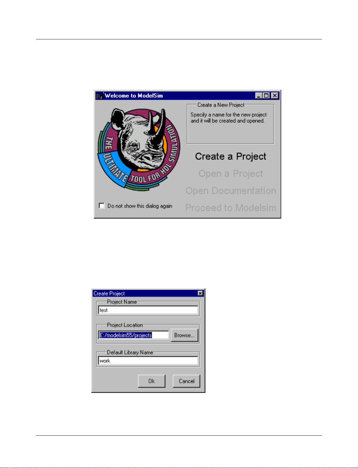
Step 1 — Create a new project
1 Select Create a Project from the Welcome to ModelSim screen that opens the first time
you start ModelSim. If this screen is not available, you can enable it by selecting Help >
Enable Welcome (Main window).
Getting started with projects
You can also use the File > New > Project (Main window) command to create a new
project.
2
Clicking the Create a Project button opens the Create Project dialog box.
ModelSim SE User’s Manual Projects and system initialization 2-29
Page 30
Getting started with projects
3 Specify a Project Name and Project Location. The location is where the pro ject .mpf file
and any copied source files will be stored. You can leave the Default Library Name set to
"work," or specify a different name if desired. The name that is specified will be used to
create a working library subdirectory within the Project Location.
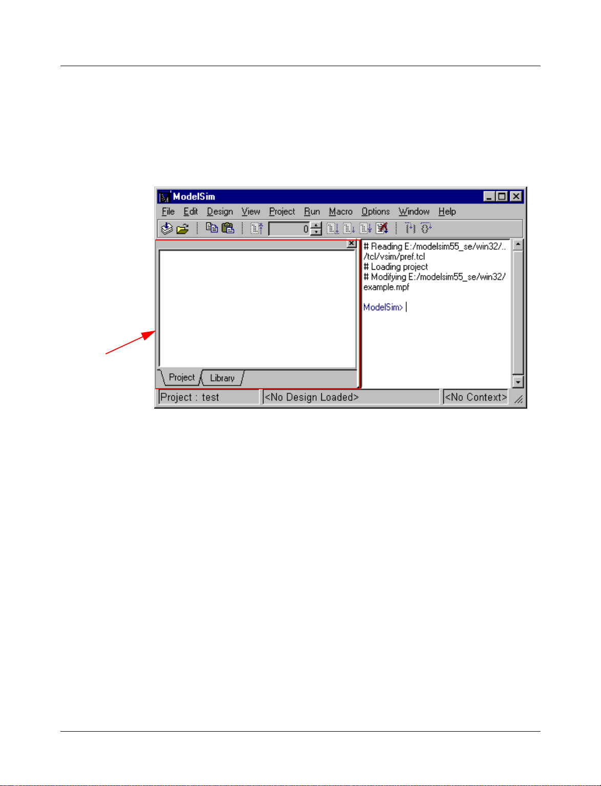
After selecting OK, you will see a blank Project page in the workspace area of the Main
window. You can hide or show the workspace at any time using the View > Hide/Show
Workspace command.
workspace
The name of the current project is shown at the bottom left corner of the Main window.
2-30 Pr ojects and system initialization ModelSim SE User’s Manual
Page 31

Step 2 — Add files to the project
Your right mouse button (2nd button in Windows ; 3rd button in UNIX) gives qu ick access
to project commands. When you right-click in the wor kspace, a context menu appear s. The
menu that appears depends on where you click in the workspace.
Getting started with projects
1 Right click in a blank area on the Project page and select Add file to Project. This opens
the Add file to Project dialog. You can also select Project > Add file to Project from the
menu bar.
2 Specify one or more files you want to add to the project. (The files used in this example are
available in the examples directory that is installed along with ModelSim.)
3 For the files you’re adding, choose whether to reference them from their current location
or copy them into the project directory.
ModelSim SE User’s Manual Projects and system initialization 2-31
Page 32

Getting started with projects
Step 3 — Compile the files
1 To compile the files, right click in the Project page and select Compile All. You can also
select Project > Compile All from the menu bar.
2 Once compilation is finished, click the Library tab and you’ll see the two compiled designs.
2-32 Pr ojects and system initialization ModelSim SE User’s Manual
Page 33

Step 4 — Simulate a design
1 To simulate one of the designs, either double-click the name or right click the name and
select Load. A new page appears showing the structure of the current active simulation.
Getting started with projects
At this point you are ready to run the simulation and analyze your results. You often do this
by adding signals to the Wave window and running the simulation for a given period of
time. See the ModelSim Tutorial for examples.
Other project operations
In addition to the four actions just discussed, the following are common project operations .
Open an existing project
When you leave a ModelSim session, ModelSim will remember the last opened project.
You can reopen it for your next session by cl icking Open Project in the Welcome to
ModelSim dialog. You can also open an existing project by selecting File > Open > Project
(Main window).
Close a project
Select File > Close > Project (Main window). This closes the Project page but leaves the
Library and Structure (labeled "Sim" in the graphic above) pages open in the workspace.
Delete a project
Select File > Delete > Project (Main window).
ModelSim SE User’s Manual Projects and system initialization 2-33
Page 34

Customizing project settings
Customizing project settings
Though the default project settings will work for many designs, it is easy to customize the
settings if needed. You can change the compile order and set compiler options.
Changing compile order
When you compile all files in a project, ModelSim by default compiles the files in the order
in which they were added to the project. You have two alternatives for changing the default
compile order: 1) select and compile each file individually; 2) specify a custom compile
order using the Compile Order dialog.
Note: Files can be displayed in the Project tab in alph abetical or compile order (using the
Sort by Alphabetical Order or Sort by Compile Order commands on the context menu).
Keep in mind that the order you see in th e Project tab is no t neces sarily th e or der in which
the files will be compiled.
To open the Compile Order dialog, right click in an empty area of th e Project tab and select
Compile Order. The dialog shown below opens.
move up in order
move down in order
group Verilog files
ungroup Verilog files
The group and ungroup buttons are used on Verilog files only. They allow you to group two
or more Verilog files so they are sent to the compiler at the same time. One case where you
might use this is when you have one file with a bunch of define statements and a second
file that is a Verilog module. You would want to compile these two files at the same time.
2-34 Pr ojects and system initialization ModelSim SE User’s Manual
Page 35

Setting compiler options
The VHDL and Verilog compilers (vcom and vlog, respectively) have numerous options
that affect how a design is compiled and subsequently simu lated. Outs ide of a p roject yo u
can set the defaults for all future simulations using the Options > Compile (Main window)
command. Inside of a project you can set these options on individual files or a group of
files.
To set the compiler options in a project, select the file(s) in the Project page, right click on
the file names, and select Compile Properties. The pages that appear in the resulting dialog
depend on the type of files you have selected. If you select a VHDL file, you’ll see only the
General and VHDL pages. If you select a Verilog file, you’ll see only the General and
Verilog pages. If you select both a VHDL file and a Verilog file, you’ll see all three pages
(as shown in the dialog below).
When setting options on a group of files, keep in mind the following:
• If two or more files have different settings for the same option, the checkbox in the dialog
will be "grayed out" like this:
If you change the option, you cannot change it back to a "multi- state setting" without
cancelling out of the dialog. Once you click OK, ModelSim will set the option the same
for all selected files.
• If you select a combination of VHDL and Verilog files, the options you set on the VHDL
and Verilog tabs apply only to those file types.
Customizing project settings
• Exclude File from Build
Determines whether the file is excluded from the compile.
• Compile to library
Specifies to which library you want to compile the file; defaults to the working library.
The definitions of the options on the VHDL and Verilog pages can be found in the section
"Setting default compile options"
ModelSim SE User’s Manual Projects and system initialization 2-35
(8-252).
Page 36

Accessing projects from the command line
Accessing projects from the command line
Generally, projects are used only within the ModelSim graphical user interface. However,
standalone tools will use the project file if they are invoked in the project’s root directory.
If invoked outside the project directory, th e MODELSIM environment variable can be set
with the path to the project file (<Project_Root_Dir>/<Project_Name>.mpf).
You can also use the project command
common operations on new projects. The command is to be used outside of a simulation
session.
(CR-159) from the command line to perform
2-36 Pr ojects and system initialization ModelSim SE User’s Manual
Page 37

System initialization
ModelSim goes through numerous steps as it initializes the system during startup. It
accesses various files and environment variables to determine library mappings, configure
the GUI, check licensing, and so forth.
Files accessed during startup
The table below describes the files that are read during startup. T hey are listed in the order
in which they are accessed.
File Purpose
modelsim.ini contains initial tool settings; see "Preference variables located in
location map file used by ModelSim tools to find source files based on easily
pref.tcl contains defaults for fonts, colors, prompts, window positions,
System initialization
INI files"
(B-396) for specific details on the modelsim.ini file
reallocated "soft" paths; default file name is mgc_location_map;
see "How location mapping works"
(E-438) for more details
and other simulator window characteristics; see "Preference
variables located in TCL files"
(B-406) for specific details on the
pref.tcl file
modelsim.tcl contains user-customized settings for fonts, colors, prompts,
window positions, and other simulator window characteristics;
see "Preference variables located in TCL files"
(B-406) for
specific details on the modelsim.tcl file
ModelSim SE User’s Manual Projects and system initialization 2-37
Page 38

System initialization
Environment variables accessed during startup
The table below describes the environment variables that are read during star tup. They are
listed in the order in which they are accessed. For more information on environment
variables, see "Environment variables"
Environment variable Purpose
MODEL_TECH set by ModelSim to the directory in which the binary executables reside
(e.g., ../modeltech/<platform>/)
MODEL_TECH_OVERRIDE provides an alternative directory for the binary executables;
MODEL_TECH is set to this path
MODELSIM identifies path to the modelsim.ini file
MGC_WD identifies the Mentor Graphics working directory (set by Mentor Graphics
tools)
MGC_LOCATION_MAP identifies the path to the location map file; set by ModelSim if not defined
MODEL_TECH_TCL identifies the path to all Tcl libraries installed with ModelSim
(B-393).
HOME identifies your login directory (UNIX only)
MGC_HOME identifies the path to the MGC tool suite
TCL_LIBRARY identifies the path to the Tcl library; set by ModelSim to the same path as
MODEL_TECH_TCL; must point to libraries supplied by Model
Technology
TK_LIBRARY identifies the path to the Tk library; set by ModelSim to the same path as
MODEL_TECH_TCL; must point to libraries supplied by Model
Technology
TIX_LIBRARY identifies the path to the Tix library; set by ModelSim to the same path as
MODEL_TECH_TCL; must point to libraries supplied by Model
Technology
ITCL_LIBRARY identifies the path to the [incr]Tcl library; set by ModelSim to the same
path as MODEL_TECH_TCL; must point to libraries supplied by Model
Technology
ITK_LIBRARY identifies the path to the [incr]Tk library; set by ModelSim to the same
path as MODEL_TECH_TCL; must point to libraries supplied by Model
Technology
VSIM_LIBRARY identifies the path to the Tcl files that are used by ModelSim; set by
ModelSim to the same path as MODEL_TECH_TCL; must point to
libraries supplied by Model Technology
MTI_LIB_DIR identifies the path to all Tcl libraries installed with ModelSim
2-38 Pr ojects and system initialization ModelSim SE User’s Manual
Page 39

System initialization
Environment variable Purpose
MODELSIM_TCL identifies the path to the modelsim.tcl file; this environment variable can
be a list of file pathnames, separated by semicolons (Windows) or colons
(UNIX)
Initialization sequence
The following list describes in detail ModelSim’s initialization sequence. The sequence
includes a number of conditional structures, the results of which are determined by the
existence of certain files and the current settings of environment variables.
In the steps below, names in uppercase denote environment variables (except
MTI_LIB_DIR which is a Tcl variable). Instances of $(NAME) denote paths that are
determined by an environment variable (except $(MTI_LIB_DIR) which is determined by
a Tcl variable).
1 Determines the path to the executable directory (../modeltech/<platform>/). Sets
MODEL_TECH to this path, unless MODEL_TECH_OVERRIDE exists, in which case
MODEL_TECH is set to the same value as MODEL_TECH_OVERRIDE.
2 Finds the modelsim.ini file by evaluating the following conditions:
• use MODELSIM if it exists; else
• use $(MGC_WD)/modelsim.ini; else
• use ./modelsim.ini; else
• use $(MODEL_TECH)/modelsim.ini; else
• use $(MODEL_TECH)/../modelsim.ini; else
• use $(MGC_HOME)/lib/modelsim.ini; else
• set path to ./modelsim.ini even though the file doesn’t exist
3 Finds the location map file by evaluating the following conditions:
• use MGC_LOCATION_MAP if it exists (if this variable is set to "no_map", ModelSim
skips initialization of the location map); else
• use mgc_location_map if it exists; else
• use $(HOME)/mgc/mgc_location_map; else
• use $(HOME)/mgc_location_map; else
• use $(MGC_HOME)/etc/mgc_location_map; else
• use $(MGC_HOME)/shared/etc/mgc_location_map; else
• use $(MODEL_TECH)/mgc_location_map; else
• use $(MODEL_TECH)/../mgc_location_map; else
• use no map
4 Reads various variables from the [vsim] section of the modelsim.ini file. See "[vsim]
simulator control variables"
ModelSim SE User’s Manual Projects and system initialization 2-39
(B-398) for more details.
Page 40

System initialization
5 Parses any command line arguments that were included when you started ModelSim and
6 Defines the following environment variables:
7 Initializes the simulator’s Tcl interpreter.
8 Checks for a valid license (a license is not checked out unless specified by a modelsim.ini
reports any problems.
• use MODEL_TECH_TCL if it exists; else
• set MODEL_TECH_TCL=$(MODEL_TECH)/../tcl
• set TCL_LIBRARY=$(MODEL_TECH_TCL)/tcl8.0
• set TK_LIBRARY =$(MODEL_TECH_TCL)/tk8.0
• set TIX_LIBRARY=$(MODEL_TECH_TCL)/tix4.1
• set ITCL_LIBRARY=$(MODEL_TECH_TCL)/itcl3.0
• set ITK_LIBRARY=$(MODEL_TECH_TCL)/itk3.0
• set VSIM_LIBRARY=$(MODEL_TECH_TCL)/vsim
setting or command line option).
The next four steps relate to initializing the graphical user interface.
9
Sets Tcl variable "MTI_LIB_DIR"=MODEL_TECH_TCL
10 Loads $(MTI_LIB_DIR)/pref.tcl.
11 Loads last w orking directory, project init, project history, and printer defaults from the
registry (Windows) or $(HOME)/.modelsim (UNIX).
12 Finds the modelsim.tcl file by evaluating the following conditions:
• use MODELSIM_TCL if it exists (if MODELSIM_TCL is a list of files, each file is
loaded in the order that it appears in the list); else
• use ./modelsim.tcl; else
• use $(HOME)/modelsim.tcl if it exists
That completes the initialization sequence. Also note the following about the modelsim.ini
file:
• When you change the working directory within ModelSim, the tool reads the [library],
[vcom], and [vlog] sections of the local modelsim.ini file. When you make changes in the
compiler options dialog or use the vmap command, the tool updates the appropriate
sections of the file.
• The pref.tcl file references the default .ini file via the [GetPrivateProfileString] Tcl
command. The .ini file that is read will be the default file defined at the time pref.tcl is
loaded.
2-40 Pr ojects and system initialization ModelSim SE User’s Manual
Page 41

3 - Design libraries
Chapter contents
Design library contents. . . . . . . . . . . . . . 3-42
Design unit information . . . . . . . . . . . . 3-42
Design library types . . . . . . . . . . . . . . 3-42
Working with design libraries . . . . . . . . . . . . 3-43
Creating a library . . . . . . . . . . . . . . 3-43
Managing library contents . . . . . . . . . . . 3-44
Assigning a logical name to a design library . . . . . . . 3-47
Moving a library . . . . . . . . . . . . . . 3-49
Specifying the resource libraries . . . . . . . . . . . 3-50
VHDL resource libraries . . . . . . . . . . . . 3-50
Predefined libraries . . . . . . . . . . . . . 3-50
Alternate IEEE libraries supplied . . . . . . . . . . 3-51
VITAL 2000 library . . . . . . . . . . . . . 3-51
Rebuilding supplied libraries . . . . . . . . . . . 3-51
Regenerating your design libraries . . . . . . . . . 3-51
Verilog resource libraries . . . . . . . . . . . . 3-52
Maintaining 32-bit and 64-bit versions in the same library . . . 3-52
Importing FPGA libraries . . . . . . . . . . . . . 3-53
VHDL contains libraries, which are objects that contain compiled design units; libraries
are given names so they may be referenced. Verilog designs simulated with in ModelSim
are compiled into libraries as well.
ModelSim SE User’s Manual Design libraries 3-41
Page 42

Design library contents
Design library contents
A design library is a directory that serves as a repository for compiled design units. The
design units contained in a design library consist of VHDL entities, packages, architectures,
and configurations; and Verilog modules and UDPs (user defined primitiv es) . The design
units are classified as follows:
• Primary design units
Consist of entities, package declarations, configuration declarations, modules, and
UDPs. Primary design units within a given library must have unique names.
• Secondary design units
Consist of architecture bodies and package bodies. Secondary d esign units are associated
with a primary design unit. Architectures by the same name can exist if they are
associated with different entities.
Design unit information
The information stored for each design unit in a design library is:
• retargetable, executable code
• debugging information
• dependency information
Design library types
There are two kinds of design libraries: working libr aries and resource lib raries. A working
library is the library into which a design unit is placed after compilation. A resource library
contains design units that can be referenced within the design unit being compiled. Only
one library can be the working library; in contrast, any number of libraries (including the
working library itself) can be resource libraries during a compilation.
The library named work has special attributes within ModelSim; it is predefined in the
compiler and need not be declared explicitly (i.e. library work). It is also the library name
used by the compiler as the default destination of compiled design units. In other words the
work library is the working library. In all other aspects it is the same as any other library.
3-42 Design libraries ModelSim SE User’s Manual
Page 43

Working with design libraries
The implementation of a design library is not defined within standard VHDL or Verilog.
Within ModelSim, design libraries are implemented as directories and can have any legal
name allowed by the operating system, with one exception; extended identifiers are not
supported for library names.
Creating a library
When you create a project (see "Getting started with projects" (2-28)), ModelSim
automatically creates a working design library. If you don’t create a project, you need to
create a working design library before you run the compiler. This can be done from either
the command line or from the ModelSim graphic interface.
From the ModelSim prompt or a UNIX/DOS prompt, use this vlib command
vlib <directory_pathname>
To create a new library with the ModelSim graphic interface, select Design > Create a New
Library (Main window). This brings up a dialog box that allows you to specify the library
name and its logical mapping.
Working with design libraries
(CR-249):
The Create a New Library dialog box includes these options:
• Create a new library and a logical mapping to it
Type the new library name into the Library Name field. This creates a library subdirectory in your current working directory, initially mapped to itself. Once created, the
mapped library is easily remapped to a different library.
• Create a map to an existing library
Type the new library name into the Library Name field, then type into the Library
Maps to field or Browse to select a library name for the mapping.
• Library Name
Type the new library name into this field.
ModelSim SE User’s Manual Design libra ries 3-43
Page 44

Working with design libraries
• Library Maps to
Type or Browse for a mapping for the specified library. This field can be changed only
when the Create a map to an existing library option is selected.
When you cli ck OK, ModelSim creates the specified library directory and writes a
specially-formatted file named _info into that directory. The _info file must remain in the
directory to distinguish it as a ModelSim library.
The new map entry is written to the modelsim.ini file in the [Library] section. See
"[Library] library path variable s"
Note: Remember that a design library is a s pecial kind of directory; the o nly way to create
a library is to use the ModelSim GUI or the vlib command
using UNIX or Windows commands.
Managing library contents
Library contents can be viewed, deleted, recompiled, edited and so on using either the
graphic interface or command line.
The Library page in the Main window workspace provides access to design units
(configurations, modules, packages, entities, and architectures) in a library. Note the icons
identify whether a unit is an entity (E), a module (M), and so forth.
(B-396) for more information.
(CR-249). Do not create libraries
The Library page includes these options:
• Library
Select the library you wish to view from the drop-down list. Related command line
command is vdir (CR-223).
3-44 Design libraries ModelSim SE User’s Manual
Page 45

Working with design libraries
• DesignUnit/Description list
Select a plus (+) box to view the associated architecture, or select a minus (–) box to hide
the architecture.
The Library page also has two context menus that you access with y our right mous e button
(Windows—2nd button, UNIX—3rd button).One menu is accessed by right-clicking a
design unit name; the second is accessed by right-clicking a blank area in the Desig ns page.
The graphic below shows the two menus.
The context menu at the left includes the following commands:
• Load
Simulates the selected design unit and opens a structure page in the workspace. Related
command line command is vsim
(CR-258).
• Edit
Opens the selected design unit in the Source window.
• Refresh
Rebuilds the library image of the selected item(s) without using source code. Related
command line command is vcom
(CR-217) with the -refresh argument.
• Recompile
Recompiles the selected design unit. Related command line command is vcom
(CR-217).
• Delete
Deletes the selected design unit. Related command line command is vdel
(CR-222).
Deleting a package, configuration, or entity will remove the design unit from the library.
If you delete an entity that has one or more architectures, the entity and all its associated
architectures will be deleted.
ModelSim SE User’s Manual Design libra ries 3-45
Page 46

Working with design libraries
You can also delete an architecture without deleting its associated entity. Expand the
entity, right-click the desired architecture name, and select Delete. You are prompted for
confirmation before any design unit is actually deleted.
The second context menu has the following options:
• Load
Opens the Load Design dialog box. See "Simulating with the graphic interface"
for details. Related command line command is vsim
• Create Library
Opens the Create a New Library dialog box. See "Creating a library"
chapter for details. Related command line command is vlib
• View
Provides va rious options for displaying design units.
• Update
Reloads the library in case any of the design units were modified outside of the current
session (e.g., by a script or another user).
(8-256)
(CR-258).
(3-43) earlier in this
(CR-249).
3-46 Design libraries ModelSim SE User’s Manual
Page 47

Assigning a logical name to a design library
VHDL uses logical library names that can be mapped to ModelSim library directories. By
default, ModelSim can find libraries in your current directory (assuming they have the right
name), but for it to find libraries located elsewhere, you need to map a logical library name
to the pathname of the library.
You can use the GUI, a command, or a pro j ect to as sign a log ical name to a design library.
Library mappings with the GUI
To associate a logical name with a library, select Design > Browse Libraries (Main
window). This brings up a dialog box that allows you to view, add, edit, and delete
mappings, as shown below:
Working with design libraries
The Library Browser dialog box includes these options:
• Show
Choose the mapping and library scope to view from the drop-down list.
• Library/Type list
To view the contents of a library
Select the library, then click the View button. This brings up the Library page
(3-44) in
the Main window. From there you can also delete design units from the library.
To create a new library mapping
Click the Add button. This brings up Create a New Library
(3-43) dialog box that
allows you to enter a new logical library name and the pathname to which it is to be
mapped.
It is possible to enter the name of a non-existent directory, but the specified directory
must exist as a ModelSim library before you can compile design units into it. ModelSim
will issue a warning message if you try to map to a non-existent directory.
ModelSim SE User’s Manual Design libra ries 3-47
Page 48

Working with design libraries
To edit an existing library mapping
Select the desired mapping entry, then click the Edit button. This brings up a dialog box
that allows you to modify the logical library name and the pathname to which it is
mapped. Selecting Delete removes an existing library mapping, but it does not delete the
library. The library can be deleted with this vdel command
vdel -lib <library_name> -all
Library mapping from the command line
You can issue a command to set the mapping between a logical library name and a
directory; its form is:
vmap <logical_name> <directory_pathname>
This command may be invoked fr om either a UNIX/DOS prompt or fro m the command line
within ModelSim.
(CR-222):
When you use vmap
(CR-257) this way you are modifying the modelsim.ini file. You can
also modify modelsim.ini manually by adding a mapping line. To do this, edit the
modelsim.ini file using any text editor and add a line under the [Library] section heading
using the syntax:
<logical_name> = <directory_pathname>
More than one logical name can b e mapped to a single directo ry. For examp le, suppose th e
modelsim.ini file in the current working directory contains following lines:
[Library]
work = /usr/rick/design
my_asic = /usr/rick/design
This would allow you to use either the logical name work or my_asic in a library or use
clause to refer to the same design library.
Unix symbolic links
You can also create a UNIX symbolic link to the librar y using the host p latform comm and:
ln -s <directory_pathname> <logical_name>
The vmap command (CR-257) can also be used to display the mapping of a logical library
name to a directory. To do this, enter the shortened form of the command:
vmap <logical_name>
Library search rules
The system searches for the mapping of a logical name in the following order:
• First the system looks for a modelsim.ini file.
• If the system doesn’t find a modelsim.ini file, or if the specified logical name does not
exist in the modelsim.ini file, the system searches the current working directory for a
subdirectory that matches the logical name.
An error is generated by the compiler if you specify a logical name that does not resolve to
an existing directory.
3-48 Design libraries ModelSim SE User’s Manual
Page 49

Moving a library
Working with design libraries
See also
See "ModelSim Commands" (CR-9) for more information about the library management
commands, "ModelSim Graphi c Interface"
user interface, and "Projects and system initialization"
(8-149) for more information about the grap hical
(2-25) for more information about the
modelsim.ini file.
Individual design units in a design library cannot be moved. An entire design library can
be moved, however, by u sing standard ope rating system comm ands for moving a directory.
ModelSim SE User’s Manual Design libra ries 3-49
Page 50

Specifying the resource libraries
Specifying the resource libraries
VHDL resource libraries
Within a VHDL source file, you can u se the VHDL library clause to specify logical names
of one or more resource libr aries to be referen ced in the subsequent d esign u nit. The scop e
of a library clause includes the text region that starts immediately after the library clause
and extends to the end of the declarative region of the associated design unit. It does not
extend to the next design unit in the file.
Note that the library clause is not used to specify the working library into which the design
unit is placed after compilation; the vcom command
to the current working library. By default, this is the library named work. To change the
current working library, you can use vcom -work and specify the name of the desired target
library.
Predefined libraries
Certain resource libraries are predefined in standard VHDL. The library named std
contains the packages standard and textio, which should not be modified. The contents of
these packages and other aspects o f th e p redefin ed langua ge en viro nmen t are docu mented
in the IEEE Standard VHDL Language Reference Manua l, Std 1076- 1987 and ANSI /IEEE
Std 1076-1993. See also, "Using the TextIO package"
A VHDL use clause can be used to select specific declarations in a library or package that
are to be visible within a design unit during compilation. A use clause references the
compiled version of the package—not the source.
(CR-217) adds compiled design units
(4-60).
By default, every design unit is assumed to contain the following declarations:
LIBRARY std, work;
USE std.standard.all
To specify that all declarations in a library or package can be referenced, you can add the
suffix .all to the library/package name. For example, the use clause above specifies that all
declarations in the package standard in the design library named std are to be visible to
the VHDL design file in which the use clause is placed. Other libraries or packages are not
visible unless they are explicitly specified using a library or use clause.
Another predefined library is work, the library where a design unit is stored after it is
compiled as described earlier. There is no limit to the number of libraries that can be
referenced, but only one library is modified during compilation.
3-50 Design libraries ModelSim SE User’s Manual
Page 51

Alternate IEEE libraries supplied
The installation directory may contain two or more versions of the IEEE library:
• ieeepure
Contains only IEEE approved std_logic_1164 packages (accelerated for ModelSim).
• ieee
Contains precompiled Synopsys and IEEE arithmetic packages which have been
accelerated by Model Technology including math_complex, math_real, numeric_bit,
numeric_std, std_logic_1164, std_logic_misc, std_logic_textio, std_logic_ ari th,
std_logic_signed, std_logic_unsigned, vital_primitives, vital_timing, and vital_memory.
You can select which library to use by changing the mapping in the modelsim.ini file. The
modelsim.ini file in the installation directory defaults to the ieee library.
VITAL 2000 library
ModelSim versions 5.5 and later include a separate VITAL 2000 library that contains an
accelerated vital_memory package.
You’ll need to add a use clause to your VHDL code to access the package. For example:
LIBRARY vital2000;
USE vital2000.vital_memory.all
Specifying the resource libraries
Also, when you compile, use the -vital2000 switch to vcom (CR-217).
Rebuilding supplied libraries
Resource libraries are supplied precompiled in the modeltech installation directory. If you
need to rebuild these libraries, the sources are provided in the vhdl_src directory; a macro
file is also provided for Wind ows platfo rms (rebldlibs.do). To rebuild the libraries, invoke
the DO file from within ModelSim with this command:
do rebldlibs.do
(Make sure your current directory is the modeltech install directory before you run this file.)
Shell scripts are provided for UNIX (rebuild_libs.csh and rebuild_libs.sh). To rebuild the
libraries, execute one of the rebuild_libs scripts while in the modeltech directory.
Note: Because accelerated subprograms require attributes that are available o nly under the
1993 standard, many of the libraries are built using vcom
Regenerating your design libraries
Depending on your current ModelSim version, you may need to r egenerate your design
libraries before running a simulation. Check the installation README file to see if your
libraries require an update. You can regenerate your design libraries using the Refresh
command from the Library page context menu (see "Managin g library contents"
by using the -refresh argument to vcom
From the command line, you would use vcom with the -refresh option to update VHDL
design units in a lib rary , and vlog with the -refresh option to update Verilog design units.
By default, the work library is updated; use -work <library> to update a different library.
For example, if you have a library named mylib that contains both VHDL and Verilog
design units:
(CR-217) with the -93 option.
(3-44)), or
(CR-217) and vlog (CR-250).
ModelSim SE User’s Manual Design libra ries 3-51
Page 52

Specifying the resource libraries
vcom -work mylib -refresh
vlog -work mylib -refresh
An important feature of -refresh is that it rebuilds the library image without using source
code. This means that models delivered as compiled libraries without source code can be
rebuilt for a specific release of ModelSim (4.6 and later only). In general, this works for
moving forwards or backwards on a release. Moving backwards on a release may not work
if the models used compiler switches or directives (Verilog only) that do not exist in the
older release.
Note: You don’t need to regenerate the std, ieee, vital22b, and verilog libraries. Also, you
cannot use the -refresh option to update libraries that were built before the 4.6 release.
Verilog resource libraries
ModelSim supports and encourages separate compilation of distinct portions of a Verilog
design. The vlog
(CR-250) compiler is used to compile one or more source files into a
specified library. The library thus contains pre-compiled modules and UDPs (and, per haps,
VHDL design units) that are referenced by the simulator as it loads the design. See "Library
(5-78).
usage"
Maintaining 32-bit and 64-bit versions in the same library
It is possible with ModelSim to maintain 32-bit and 64-bit versions of a design in the same
library. To do this, you must compile the design with one of the versions (32-bit or 64-bit),
and "refresh" the design with the other version. For example:
Using the 32-bit version of ModelSim:
vcom file1.vhd
vcom file2.vhd
Next, using the 64-bit version of ModelSim:
vcom -refresh
Do not compile the design with one version, and then recompile it with the other. If you do
this, ModelSim will remove the first module, because it could be "stale."
3-52 Design libraries ModelSim SE User’s Manual
Page 53

Importing FPGA libraries
ModelSim includes an import wizard for referencing and using vendor FPGA libraries. The
wizard scans for and enforces dependencies in the libraries and determines the correct
mappings and target directories.
Important: The FPGA libraries you import must be pre-compiled. Most FPGA vendors
supply pre-compiled libraries configured for use with ModelSim.
To import an FPGA library, select Design > Import Library (Main window).
Importing FPGA libraries
Follow the instructions in the wizard to complete the import.
ModelSim SE User’s Manual Design libra ries 3-53
Page 54

3-54 Des ign libraries ModelSim SE User’s Manual
Page 55

4 - VHDL Simulation
Chapter contents
Compiling VHDL designs . . . . . . . . . . . . . 4-57
Creating a design library . . . . . . . . . . . . 4-57
Invoking the VHDL compiler. . . . . . . . . . . 4-57
Dependency checking. . . . . . . . . . . . . 4-57
Simulating VHDL designs . . . . . . . . . . . . . 4-58
Invoking the simulator from the Main window . . . . . . 4-58
Invoking Code Coverage with vsim . . . . . . . . . 4-59
Using the TextIO package . . . . . . . . . . . . . 4-60
Syntax for file declaration. . . . . . . . . . . . 4-60
Using STD_INPUT and STD_OUTPUT within ModelSim . . . 4-61
TextIO implementation issues . . . . . . . . . . . . 4-62
Writing strings and aggregates . . . . . . . . . . 4-62
Reading and writing hexadecimal numbers . . . . . . . 4-63
Dangling pointers . . . . . . . . . . . . . . 4-63
The ENDLINE function . . . . . . . . . . . . 4-63
The ENDFILE function . . . . . . . . . . . . 4-63
Using alternative input/output files . . . . . . . . . 4-64
Providing st imulus . . . . . . . . . . . . . 4-64
Obtaining the VITAL specification and source code . . . . . . 4-65
VITAL packages . . . . . . . . . . . . . . . 4-65
ModelSim VITAL compliance. . . . . . . . . . . . 4-66
VITAL compliance checking . . . . . . . . . . . 4-66
VITAL compliance warnings . . . . . . . . . . . 4-66
Compiling and Simulating with accelerated VITAL packages . . . 4-67
Util package . . . . . . . . . . . . . . . . 4-68
get_resolution() . . . . . . . . . . . . . . 4-68
init_signal_spy() . . . . . . . . . . . . . . 4-69
to_real() . . . . . . . . . . . . . . . . 4-70
to_time() . . . . . . . . . . . . . . . . 4-71
This chapter provides an overview of compilation and simulation for VHDL designs within
the ModelSim environment, using the TextIO package with ModelSim; ModelSim’s
implementation of the VITAL (VHDL Initiative Towards ASIC Libraries) specification for
ASIC modeling; and documentation on ModelSim’s special built-in utilities package.
The TextIO package is defined within the VHDL L an gua ge Ref erence Manuals, IEEE Std
1076-1987 and IEEE Std 1076-1993; it allows human-readable text input from a declared
source within a VHDL file during simulation.
ModelSim SE User’s Manual VHDL Simulation 4-55
Page 56

Compiling and simulating with the GUI
Many of the examples in this chapter are shown from the command line. For compiling and
simulating within a project or the ModelSim GUI, see:
• Getting started with projects
• Compiling with the graphic interface (8-250)
• Simulating with the graphic interface (8-256)
ModelSim variables
Several variables are available to control simulation, provide simulator state feedback, or
modify the appearance of the ModelSim GUI. To take effect, some variables, such as
environment variables, must be set prior to simulation. See Appendix B - ModelSim
Variables for a complete listing of ModelSim variables.
(2-28)
4-56 VHDL Simu lation ModelSim SE User’s Manual
Page 57

Compiling VHDL designs
Creating a design library
Before you can compile your design, you must create a library in which to store the
compilation results. Use vlib
vlib work
This creates a library named work. By default, compilation results are stored in the work
library.
Note: The work library is actually a subdirectory named work. This subdirectory contains
a special file named _info. Do not create libraries using UNIX, MS Windows, or DOS
commands – always use the vlib command
Compiling VHDL designs
(CR-249) to create a new library. For example:
(CR-249).
See "Design libraries"
Invoking the VHDL compiler
ModelSim compiles one or more VHDL design units with a single invocation of vcom (CR-
, the VHDL compiler. The design units are compiled in the order that they appear on
217)
the command line. For VHDL, the order of compilation is important – you must compile
any entities or configurations before an architecture that references them.
You can simulate a design containing units written with both the 1076 -1987 and 1076
-1993 versions of VHDL. To do so you will need to compile units from each VHDL version
separately. The vcom
by default; use the -93 option with vcom
1076 -1993. You can also change the default by modifying the modelsim.ini file (see
"Preference variables located in INI files"
Dependency checking
Dependent design units must be reanalyzed when the design units they depend on are
changed in the library. vcom
have changed. For example, if you keep an entity and its architectures in the same source
file and you modify only an architecture and recompile the source file, the entity
compilation results will remain unchanged and you will not have to recompile design units
that depend on the entity.
(3-41) for additional information on working with libraries.
(CR-217) command compiles units written with version 1076 -1987
(CR-217) to compile units written with version
(B-396) for more information).
(CR-217) determines whether or not the compilation results
ModelSim SE User’s Manual VHDL Simulation 4-57
Page 58

Simulating VHDL designs
Simulating VHDL designs
After compiling the design units, you can simulate your designs with vsim (CR-258). This
section discusses simulation from the UNIX or Windows/DOS command lin e. You can
also use a project to simulate (see "Getting started with projects"
dialog box (see "Simulating with the graphic interface"
Note: Simulation normally stops if a failure occurs; however, if a bounds check on a signal
fails the simulator will continue running.
Invoking the simulator from the Main window
For VHDL, invoke vsim (CR-258) with the name of the configuration, or entity/architecture
pair. Note that if you specify a configuration you may not specify an architecture.
(2-28)) or the Load Design
(8-256)).
This example invokes vsim
vsim my_asic structure
(CR-258) on the entity my_asic and the architecture structure:
If a design unit name is not specified, vsim (CR-258) will present the Load Design dialog
box from which you can choose a configuration or entity/architecture pair. See "Simulating
with the graphic interface"
(8-256) for more information.
Selecting the time resolution
The simulation time resolution is 1 ns by default. You can select a specific time resolution
with the vsim
(CR-258) -t option or from the Lo ad Design dialo g box. Available resolut ions
are: 1x, 10x or 100x of fs, ps, ns, us, ms, or sec.
For example, to run in picosecond resolution, or 10ps resolution respectively:
vsim -t ps topmod
vsim -t 10ps topmod
Note that there is no space between the value and the units (i.e.., 10ps, not 10 ps).
The default time resolution can also be changed by modifying the Resolution
(B-400)
variable in the modelsim.ini file. You can view the current resolution by invoking the
report command
See "Preference variables located in INI files"
(CR-168) with the simulat or state option.
(B-396) for more information on modifying
the modelsim.ini file.
vsim
(CR-258) is capable of annotating a design using VITAL compliant models with timing
data from an SDF file. You can specify the min:typ:max delay by invoking vsim with the
-sdfmin, -sdftyp and -sdfmax options. Using the SDF file f1.sdf in the current work
directory, the following invocation of vsim annotates maximum timing values for the
design unit my_asic:
vsim -sdfmax /my_asic=f1.sdf my_asic
Timing check disabling
By default, the timing checks within VITAL models are enabled. They can be disabled with
the +notimingchecks option.
For example:
vsim +notimingchecks topmod
4-58 VHDL Simu lation ModelSim SE User’s Manual
Page 59

Invoking Code Coverage with vsim
ModelSim’s Code Coverage feature gives you graphical and report file feedback on how
the source code is being executed. It allows line number execution statistics to be kept by
the simulator. It can be used duri ng any des ign phase and in all levels and types of designs.
For complete details, see Chapter 10 - Code Coverage.
To acquire code coverage statistics, the -coverage switch must be specified during the
command-line invocation of the simulator.
vsim -coverage ...
This will allow you to use the various code coverage commands: coverage clear (CR-92),
coverage reload
(CR-93), and coverage report (CR-94).
Simulating VHDL designs
ModelSim SE User’s Manual VHDL Simulation 4-59
Page 60

Using the TextIO package
Using the TextIO package
To access the routines in TextIO, include the following statement in your VHDL source
code:
USE std.textio.all;
A simple example using the package TextIO is:
USE std.textio.all;
ENTITY simple_textio IS
END;
ARCHITECTURE simple_behavior OF simple_textio IS
BEGIN
PROCESS
VARIABLE i: INTEGER:= 42;
VARIABLE LLL: LINE;
BEGIN
WRITE (LLL, i);
WRITELINE (OUTPUT, LLL);
WAIT;
END PROCESS;
END simple_behavior;
Syntax for file declaration
The VHDL’87 syntax for a file declaration is:
file identifier : subtype_indication is [ mode ] file_logical_name ;
where "file_logical_name" must be a string expression.
The VHDL’93 syntax for a file declaration is:
file identifier_list : subtype_indication [ file_open_information ] ;
You can specify a full or relative path as the file_logical_name; for example (VHDL’87):
file filename : TEXT is in "usr/rick/myfile";
Normally if a file is declared within an architecture, p rocess, or p ackage, the file is op ened
when you start the simulator and is closed when you exit from it. If a file is declared in a
subprogram, the file is opened when the subprogram is called and closed when execution
RETURNs from the subprogram. Alternatively, the opening of files can be delayed until
the first read or write by setting the DelayFileOpen variable in the modelsim.ini file. Also,
the number of concurrently open files can be controlled by the ConcurrentFileLimit
variable. These variables help you manage a large number of files during simulation. See
Appendix B - ModelSim Variables for more details.
4-60 VHDL Simu lation ModelSim SE User’s Manual
Page 61

Using STD_INPUT and STD_OUTPUT within ModelSim
The standard VHDL’87 TextIO package contains the following file declarations:
file input: TEXT is in "STD_INPUT";
file output: TEXT is out "STD_OUTPUT";
The standard VHDL’93 TextIO package contains these file declarations:
file input: TEXT open read_mode is "STD_INPUT";
file output: TEXT open write_mode is "STD_OUTPUT";
STD_INPUT is a file_logical_name that refers to characters that are entered interactively
from the keyboard, and STD_OUTPUT refers to text that is displayed on the screen.
In ModelSim, reading from the STD_INPUT file allows you to enter text into the current
buffer from a prompt in the Main window. The last line written to the STD_OUTPUT file
appears at the prompt.
Using the TextIO package
ModelSim SE User’s Manual VHDL Simulation 4-61
Page 62

TextIO implementation issues
TextIO implementation issues
Writing strings and aggregates
A common error in VHDL source code occurs when a call to a WRITE procedur e does not
specify whether the argument is of type STRING or BIT_VECTOR. For example, the
VHDL procedure:
WRITE (L, "hello");
will cause the following error:
ERROR: Subprogram "WRITE" is ambiguous.
In the TextIO package, the WRITE procedure is overloaded for the types STRING and
BIT_VECTOR. These lines are reproduced here:
procedure WRITE(L: inout LINE; VALUE: in BIT_VECTOR;
JUSTIFIED: in SIDE:= RIGHT; FIELD: in WIDTH := 0);
procedure WRITE(L: inout LINE; VALUE: in STRING;
JUSTIFIED: in SIDE:= RIGHT; FIELD: in WIDTH := 0);
The error occurs because the argument "hello" could be interpreted as a string or a bit
vector, but the compiler is not allowed to determine the argument type until it knows which
function is being called.
The following procedure call also generates an error:
WRITE (L, "010101");
This call is even more ambiguous, because the compiler could not determine, even if
allowed to, whether the argument "010101" should be interpreted as a string or a bit vector.
There are two possible solutions to this problem:
• Use a qualified expression to specify the type, as in:
WRITE (L, string’("hello"));
• Call a procedure that is not overloaded, as in:
WRITE_STRING (L, "hello");
The WRITE_STRING procedure simply defines the value to be a STRING and calls the
WRITE procedure, but it serves as a shell around the WRITE procedure that solves the
overloading problem. For further details, refer to the WRITE_STRING procedure in the
io_utils package, which is located in the file /modeltech/examples/io_utils.vhd.
4-62 VHDL Simu lation ModelSim SE User’s Manual
Page 63

Reading and writing hexadecimal numbers
The reading and writing of hexadecimal numbers is not specified in standard VHDL. The
Issues Screening and Analysis Committee of the VHDL Analysis and Standardization
Group (ISAC-VASG) has specified that the TextIO package reads and writes only decimal
numbers.
To expand this functionality, ModelSim supplies hexadecimal routines in the package
io_utils, which is located in the file /modeltech/examples/io_utils.vhd. To use these
routines, compile the io_utils package and then include the following use clauses in your
VHDL source code:
use std.textio.all;
use work.io_utils.all;
Dangling pointers
Dangling pointers are easily created when using the TextIO package, because
WRITELINE de-allocates the access type (pointer) that is passed to it. Following are
examples of good and bad VHDL coding styles:
Bad VHDL (because L1 and L2 both point to the same buffer):
READLINE (infile, L1); -- Read and allocate buffer
L2 := L1; -- Copy pointers
WRITELINE (outfile, L1); -- Deallocate buffer
TextIO implementation issues
Good VHDL (because L1 and L2 point to different buffers):
READLINE (infile, L1); -- Read and allocate buffer
L2 := new string’(L1.all); -- Copy contents
WRITELINE (outfile, L1); -- Deallocate buffer
The ENDLINE function
The ENDLINE function described in the IEEE Standard VHDL Language Reference
Manual, IEEE Std 1076-1987 contains invalid VHDL syntax and cannot be implemented
in VHDL. This is because access types must be passed as variables, but functions only
allow constant parameters.
Based on an ISAC-VASG recommendation the ENDLINE function has been removed
from the TextIO package. The following test may be substituted for this function:
(L = NULL) OR (L’LENGTH = 0)
The ENDFILE function
In the VHDL Language Reference Manuals, IEEE Std 1076 -1987 and IEEE Std 107 6-1993,
the ENDFILE function is listed as:
-- function ENDFILE (L: in TEXT) return BOOLEAN;
As you can see, this function is commented out of the standard TextIO package. This is
because the ENDFILE function is implicitly declared, so it can be used with files of any
type, not just files of type TEXT.
ModelSim SE User’s Manual VHDL Simulation 4-63
Page 64

TextIO implementation issues
Using alternative input/output files
You can use the TextIO package to read and write to your own files. To do this, just declare
an input or output file of type TEXT.
The VHDL’87 declaration is:
file myinput : TEXT is in "pathname.dat";
The VHDL’93 declaration is:
file myinput : TEXT open read_mode is "pathname.dat";
Then include the identifier for this file ("myinput" in this example) in the READLINE or
WRITELINE procedure call.
Providing stimulus
You can stimulate and test a design by reading vectors from a file, using them to drive
values onto signals, and testing the results. A VHDL test bench has been included with the
ModelSim install files as an example. Check for this file:
<install_dir>/modeltech/examples/stimulus.vhd
4-64 VHDL Simu lation ModelSim SE User’s Manual
Page 65

Obtaining the VITAL specification and source code
Obtaining the VITAL specification and source code
VITAL ASIC Modeling Specification
The IEEE 1076.4 VITAL ASIC Modeling Specification is available from the Institute of
Electrical and Electronics Engineers, Inc.:
IEEE Customer Service
445 Hoes Lane
Piscataway, NJ 08855-1331
Tel: (800)678-4333 ((908)562-5420 from outside the U.S.)
Fax: (908)981-9667
home page: http://www.ieee.org
VITAL source code
The source code for VITAL packages is provided in the /<install_dir>/modeltech/
vhdl_src/vital2.2b, /vital95, or /vital2000 directories.
VITAL packages
VITAL v3.0 accelerated packages are p re-com piled into th e ieee library in the installation
directory.
Note: By default, ModelSim is optimized for VITAL v3.0. You can, however, revert to
VITAL v2.2b by invok ing vsim
vital to <install_dir>/modeltech/vital2.2b.
(CR-258) with the -vital2.2b option, and by mapping library
ModelSim SE User’s Manual VHDL Simulation 4-65
Page 66

ModelSim VITAL compliance
ModelSim VITAL compliance
A simulator is VITAL compliant if it implements the SDF mapping and if it co rrectly
simulates designs using the VITAL packages, as outlined in the VITAL Model
Development Specification. ModelSim is compliant with the IEEE 1076.4 VITAL ASIC
Modeling Specification. In addition, ModelSim accelerates the VITAL_Timing and
VITAL_Primitives packages. The procedures in these packages are optimized and built
into the simulator kernel. By default, vsim
optimized procedures are functionally equivalent to the IEEE 1076.4 VITAL ASIC
Modeling Specification (VITAL v3.0).
VITAL compliance checking
Compliance checking is important in enabling VITAL acceleration; to qualify for global
acceleration, an architecture must be VITAL-level-one compliant. vcom
automatically checks for VITAL 3.0 compliance on all entities with the VITAL_Level0
attribute set, and all architectures with the VITAL_Level0 or VITAL_Level1 attribute set.
It also checks for VITAL 2000 compliance on all architectures using the vital2000 library.
If you are using VITAL 2.2b, you must turn off the compliance checking either by not
setting the attributes, or by invoking vcom
course, possible to turn off compliance checking for VITAL 3.0 as well; we strongly
suggest that you leave checking on to ensure optimal simulation.
(CR-258) uses the optimized procedures. The
(CR-217)
(CR-217) with the option -novitalcheck. It is, of
VITAL compliance warnings
The following LRM errors are printed as warnings (if they were considered errors they
would prevent VITAL level 1 acceleration); they do not affect how the architecture
behaves.
• Starting index constraint to DataIn and PreviousDataIn parameters to VITALStateTable
do not match (1076.4 section 6.4.3.2.2)
• Size of PreviousDataIn parameter is larger than the size of the DataIn parameter to
VITALStateTable (1076 .4 section 6.4.3.2.2)
• Signal q_w is read by the VITAL process but is NOT in the sensitivity list (1076.4 section
6.4.3)
The first two warnings are minor cases where the body of the VITAL 3.0 LRM is slightly
stricter than the package portion of the LRM. Since either interpretation will provide the
same simulation results, we chose to make these two cases just warn ings.
The last warning is a relaxation of the restriction on reading an internal signal that is not in
the sensitivity list. This is relaxed only for the CheckEnabled parameter s of the tim ing
checks, and only if it is not read elsewhere.
You can control the visibility of VITAL compliance-check warnings in your vcom
transcript. They can be suppressed by using the vcom -nowarn switch as in
vcom -nowarn 6. The 6 comes from the warning level printed as part of the warning, i.e.,
WARNING[6]. You can also add the following line to you r modelsim.ini file in the [vcom]
VHDL compiler control variables
[vcom]
Show_VitalChecksWarnings = 0
(CR-217)
(B-396) section.
4-66 VHDL Simu lation ModelSim SE User’s Manual
Page 67

Compiling and Simulating with accelerated VITAL packages
Compiling and Simulating with accelerated VITAL packages
vcom (CR-217) automatically recognizes that a VITAL function is being referenced from
the ieee library and generates code to call the optimized built-in routines.
Optimization occurs on two levels:
• VITAL Level-0 optimization
This is a function-by-function optimization. It applies to all level-0 architectures, and any
level-1 architectures that failed level-1 optimization.
• VITAL Level-1 optimization
Performs global optimization on a VITAL 3.0 level-1 ar chitecture that passes the VITAL
compliance checker. This is the default behavior.
Compiler options for VITAL optimization
Several vcom (CR-217) options control and provide feedback on VITAL optimization:
-O0 | -O4
Lower the optimization to a minimum with -O0 (capital oh zero). Optional. Use this to
work around bugs, increase your debugging visibility on a specific cell, or when you
want to place breakpoints on source lines that have been optimized out.
Enable optimizations with -O4 (default).
-debugVA
Prints a confirmation if a VITAL cell was optimized, or an explanation of why it was not,
during VITAL level-1 acceleration.
-vital2000
Turns on acceleration for the VITAL 2000 vital_memory package.
ModelSim VITAL built-ins will be updated in step with new releases of the VITAL
packages.
ModelSim SE User’s Manual VHDL Simulation 4-67
Page 68

Util package
Util package
get_resolution()
The util package is included in ModelSim versions 5.5 and later and serves as a container
for various VHDL utilities. The package is part of the modelsim_lib library which is
located in the modelsim tree and mapped in the default modelsim.ini file.
To access the utilities in the package, you would add lines like the following to your VHDL
code:
library modelsim_lib;
use modelsim_lib.util.all;
get_resolution() returns the current simulator resolution as a real number. For example, 1
femtosecond corresponds to 1e-15.
Syntax
resval := get_resolution();
Returns
Name Type Description
resval real The simulator resolution represented as a real
Arguments
None
Related functions
to_real() (4-70)
to_time() (4-71)
Example
If the simulator resolution is set to 10ps, and you invoke the command:
resval := get_resolution();
the value returned to resval would be 1e-11.
4-68 VHDL Simu lation ModelSim SE User’s Manual
Page 69

init_signal_spy()
Util package
The init_signal_spy() utility mirrors the value of a VHDL signal or Verilog register/ wir e
(called the spy_object) onto an existing VHDL signal or Verilog register (called the
dest_object). This allows you to reference signals, registers, or wires at any level of
hierarchy from within a VHDL architecture (e.g., a testbench).
This system task works only in ModelSim versions 5.5 and newer.
Syntax
init_signal_spy( spy_object, dest_object, verbose);
Returns
Nothing
Arguments
Name Type Description
spy_object string Required. A full hierarchical path (or relative
path with reference to the calling block) to a
VHDL signal or Verilog register/wire. Use the
path separator to which your simulation is set
(i.e., "/" or "."). A full hierarchical path must
begin with a "/" or ".". The path must be
contained within double quotes.
dest_object string Required. A full hierarchical path (or relative
path with reference to the calling block) to an
existing VHDL signal or Verilog register. Use
the path separator to which your simulation is
set (i.e., "/" or "."). A full hierarchical path
must begin with a "/" or ".". The path mus t be
contained within double quotes.
verbose integer Optional. Possible values are 0 or 1. Specifies
whether you want a message reported in the
Transcript stating that the spy_object’s value
is mirrored onto the dest_object. Default is 0,
no message.
Related functions
None
Limitations
• When mirroring the value of a Verilog register/wire onto a VHDL signal, the VHDL
signal must be of type bit, bit_vector, std_logic, or std_logic_vector.
• Mirroring slices or single bits of a vector is not supported. If you do reference a slice or
bit of a vector, the function will assume that you are referencing the entire vector.
ModelSim SE User’s Manual VHDL Simulation 4-69
Page 70

Util package
to_real()
Example
library modelsim_lib;
use modelsim_lib.util.all;
entity top is
end;
architecture ...
signal top_sig1 : std_logic;
begin
...
spy_process : process
begin
init_signal_spy("/top/uut/inst1/sig1","/top_sig1",1);
wait;
end process spy_process;
...
end;
In this example, the value of "/top/uut/inst1/sig1" will be mirrored onto
"/top_sig1".
to_real() converts the physical type time value into a real value with respect to the current
simulator resolution. The precision of the converted value is determ ined by the simulator
resolution. For example, if you were converting 1900 fs to a real and the simulator
resolution was ps, then the real value would be 2.0 (i.e. 2 ps).
Syntax
realval := to_real(timeval);
Returns
Name Type Description
realval real The time value represented as a real with
respect to the simulator resolution
Arguments
Name Type Description
timeval time The value of the physical type time
Related functions
get_resolution() (4-68)
to_time() (4-71)
Example
4-70 VHDL Simu lation ModelSim SE User’s Manual
Page 71

to_time()
Util package
If the simulator resolution is set to ps, and you enter the following fun ction:
realval := to_real(12.99 ns);
then the value returned to realval would be 12 990.0. If y ou wanted the returned v alue to be
in units of nanoseconds (ns) instead, you would use the get_resolution()
(4-68) function to
recalculate the value:
realval := 1e+9 * (to_real(12.99 ns)) * get_resolution();
If you wanted the returned value to be in units of femtoseconds (fs), you would enter the
function this way:
realval := 1e+15 * (to_real(12.99 ns)) * get_resolution();
to_time converts a real value into a time value with respect to the current simulator
resolution. The precision of the converted value is determined by the simulator resolution.
For example, if you were converting 5.9 to a time and the simulator resolution was ps, then
the time value would be 6 ps.
Syntax
timeval := to_time(realval);
Returns
Name Type Description
timeval time The real value represented as a physical type
time with respect to the simulator resolution
Arguments
Name Type Description
realval real The value of the type real
Related functions
get_resolution() (4-68)
to_real() (4-70)
Example
If the simulator resolution is set to ps, and you enter the following fun ction:
timeval := to_time(72.49);
then the value returned to timeval would be 72 ps.
ModelSim SE User’s Manual VHDL Simulation 4-71
Page 72

4-72 VHDL Simulation ModelSim SE User’s Manual
Page 73

5 - Verilog Simulation
Chapter contents
Compilation . . . . . . . . . . . . . . . . 5-75
Incremental compilation . . . . . . . . . . . . 5-76
Library usage . . . . . . . . . . . . . . . 5-78
Verilog-XL compatible compiler options. . . . . . . . 5-79
Verilog-XL ‘uselib compiler directive . . . . . . . . 5-81
Simulation . . . . . . . . . . . . . . . . . 5-84
Invoking the simulator . . . . . . . . . . . . 5-84
Simulation resolution limit . . . . . . . . . . . 5-84
Event order issues. . . . . . . . . . . . . . 5-85
Verilog-XL compatible simulator options . . . . . . . 5-86
Compiling for faster performance . . . . . . . . . . . 5-90
Compiling with -fast . . . . . . . . . . . . . 5-90
Compiling gate-level designs with -fast . . . . . . . . 5-91
Referencing the optimized design. . . . . . . . . . 5-92
Enabling design object visibility with the +acc option . . . . 5-94
Using pre-compiled libraries . . . . . . . . . . . 5-96
Cell Libraries . . . . . . . . . . . . . . . . 5-97
SDF timing annotation . . . . . . . . . . . . 5-97
Delay modes . . . . . . . . . . . . . . . 5-97
System Tasks . . . . . . . . . . . . . . . . 5-99
IEEE Std 1364 system tasks . . . . . . . . . . . 5-99
Verilog-XL compatible system tasks . . . . . . . . . 5-102
$init_signal_spy . . . . . . . . . . . . . . 5-104
Compiler Directives . . . . . . . . . . . . . . 5-106
IEEE Std 1364 compiler directives . . . . . . . . . 5-106
Verilog-XL compatible compiler directives . . . . . . . 5-106
Using the Verilog PLI/VPI. . . . . . . . . . . . . 5-108
Registering PLI applications . . . . . . . . . . . 5-108
Registering VPI applications . . . . . . . . . . . 5-110
Compiling and linking PLI/VPI applications . . . . . . . 5-111
The PLI callback reason argument . . . . . . . . . 5-117
The sizetf callback function . . . . . . . . . . . 5-119
PLI object handles. . . . . . . . . . . . . . 5-119
Third party PLI applications . . . . . . . . . . . 5-120
Support for VHDL objects . . . . . . . . . . . 5-121
IEEE Std 1364 ACC routines . . . . . . . . . . . 5-122
IEEE Std 1364 TF routines . . . . . . . . . . . 5-123
Verilog-XL compatible routines . . . . . . . . . . 5-125
64-bit support in the PLI . . . . . . . . . . . . 5-125
PLI/VPI tracing . . . . . . . . . . . . . . 5-125
This chapter describes how to compile and simulate Verilog designs with ModelSim
Verilog. ModelSim Verilog implements the Verilog language as defined by the IEEE Std
1364, and it is recommended that you obtain this specification as a reference manual.
ModelSim SE User’s Manual Verilog Simulation 5-73
Page 74

In addition to the functionality described in the IEEE Std 1364, ModelSim Verilog includes
the following features:
• Standard Delay Format (SDF) annotator compatible with many ASIC and FPGA vend or's
Verilog libraries
• Value Change Dump (VCD) file extensions for ASIC vendor test tools
• Dynamic loading of PLI/VPI applications
• Compilation into retargetable, executable code
• Incremental design compilation
• Extensive support for mixing VHDL and Verilog in the same design (including SDF
annotation)
• Graphic Interface that is common with ModelSim VHDL
• Extensions to provide compatibility with Verilog-XL
The following IEEE Std 1364 functionality is partially implemented in Mode lSim Verilog:
• Verilog Procedural Interface (VPI) (see /<install_dir>/modeltech/docs/technotes/
Verilog_VPI.note for details)
Many of the examples in this chapter are shown from the command line. For compiling and
simulating within a project or ModelSim’s GUI see:
• Getting started with projects
• Compiling with the graphic interface (8-250)
• Simulating with the graphic interface (8-256)
ModelSim variables
Several variables are available to control simulation, provide simulator state feedback, or
modify the appearance of the ModelSim GUI. To take effect, some variables, such as
environment variables, must be set prior to simulation. See Appendix B - ModelSim
Variables for a complete listing of ModelSim variables.
(2-28)
5-74 Ver ilog Simulation ModelSim SE User’s Manual
Page 75

Compilation
Compilation
Before you can simulate a Verilog design, you must first create a library and compile the
Verilog source code into that library. This section provides detailed information on
compiling Verilog designs. For information on creating a design library, see Chapter 3 -
Design libraries.
The ModelSim Verilog compiler, vlog, compiles Verilog source code into retargetable,
executable code, meaning that the library format is compatible across all supported
platforms a nd that you can simulate your design on any platform without having to
recompile your design specifically for that platform. As you compile your design, the
resulting object code for modules and UDPs is generated into a library. By default, the
compiler places results into the work library. You can specify an alternate library with the
-work option. The following is a simple example of how to create a work library, compile
a design, and simulate it:
Contents of top.v:
module top;
initial $display("Hello world");
endmodule
Create the work library:
% vlib work
Compile the design:
% vlog top.v
-- Compiling module top
Top level modules:
top
View the contents of the work library (optional):
% vdir
MODULE top
Simulate the design:
% vsim -c top
# Loading work.top
VSIM 1> run -all
# Hello world
VSIM 2> quit
In this example, the simulator was run without the graphic interface by specifying the -c
option. After the design was loaded, the simulator command run -all was entered, meaning
to simulate until there are no more simulator events. Finally, the quit command was entered
to exit the simulator. By default, a log of the simulation is written to the file "transcript" in
the current directory.
ModelSim SE User’s Manual Verilog Simulation 5-75
Page 76

Compilation
Incremental compilation
By default, ModelSim Verilog supports incremental compilation of designs, thus saving
compilation time when you modify your design. Unlike other Verilog simulators, there is
no requirement that you compile the entire design in one invocation of the compiler
(although, you may wish to do so to optimize performance; see "Compiling for faste r
performance"
You are not required to compile your design in any particular order because all mo dule and
UDP instantiations and external hierarchical references are resolved when the design is
loaded by the simulator. Incremental compilation is made possible by deferring these
bindings, and as a result some errors cannot be detected during compilation. Commonly,
these errors include: modules that were referenced but not compiled, incorrect port
connections, and incorrect hierarchical references.
The following example shows how a hierarchical design can be compiled in top-down
order:
Contents of top.v:
module top;
or2(n1, a, b);
and2(n2, n1, c);
endmodule
(5-90)).
Contents of and2.v:
module and2(y, a, b);
output y;
input a, b;
and(y, a, b);
endmodule
Contents of or2.v:
module or2(y, a, b);
output y;
input a, b;
or(y, a, b);
endmodule
Compile the design in top down order (assumes work library already exists):
% vlog top.v
-- Compiling module top
Top level modules:
top
% vlog and2.v
-- Compiling module and2
Top level modules:
and2
% vlog or2.v
-- Compiling module or2
Top level modules:
or2
5-76 Ver ilog Simulation ModelSim SE User’s Manual
Page 77

Compilation
Note that the compiler lists each module as a top level module, although, ultimately, only
"top" is a top-level module. If a module is not referenced by another module compiled in
the same invocation of the compiler, then it is listed as a top level module. This is just an
informative message and can be ignored during incremental compilation. The message is
more useful when you compile an entire desi gn in one invocation of the compiler and nee d
to know the top level module names for the simulator. For example,
% vlog top.v and2.v or2.v
-- Compiling module top
-- Compiling module and2
-- Compiling module or2
Top level modules:
top
The most efficient method of incremental compilation is to manually compile only the
modules that have changed. This is not always convenient, especially if your source files
have compiler directive interdependencies (such as macros). In this case, you may prefer to
always compile your entire design in one invocation of the compiler. If you specify the
-incr option, the compiler will automatically determine which modules have changed and
generate code only for those modules. This is not as efficient as manual incremental
compilation because the compiler must scan all of the source code to determine which
modules must be compiled.
The following is an example of how to compile a design with automatic incremental
compilation:
% vlog -incr top.v and2.v or2.v
-- Compiling module top
-- Compiling module and2
-- Compiling module or2
Top level modules:
top
Now, suppose that you modify the functionality of the "or2" module:
% vlog -incr top.v and2.v or2.v
-- Skipping module top
-- Skipping module and2
-- Compiling module or2
Top level modules:
top
The compiler informs you that it skipped the modules "top" and "and2", and compiled
"or2".
Automatic incremental compilation is intelligent about when to compile a module. For
example, changing a comment in your source code does not result in a recompile; however,
changing the compiler command line options results in a recompile of all modules.
Note: Changes to your source code that do not change functionality but that do affect
source code line numbers (such as ad ding a commen t line) will cause all affected modules
to be recompiled. This happens because debug information must be kept current so that
ModelSim can trace back to the correct areas of the source code.
ModelSim SE User’s Manual Verilog Simulation 5-77
Page 78

Compilation
Library usage
All modules and UDPs in a Verilog design must be compiled into one or more libraries.
One library is usually sufficient for a simple design, but you may want to organize your
modules into variou s libraries for a compl ex design. If your des i gn us es di f ferent mod ul es
having the same name, then you are required to put those modules in different libraries
because design unit names must be unique within a library.
The following is an example of how you may organize your ASIC cells into one library and
the rest of your design into another:
% vlib work
% vlib asiclib
% vlog -work asiclib and2.v or2.v
-- Compiling module and2
-- Compiling module or2
Top level modules:
and2
or2
% vlog top.v
-- Compiling module top
Top level modules:
top
Note that the first compilation uses the -work asiclib option to instruct the compiler to
place the results in the asiclib library rather than the default work library.
Since instantiation bindings are not determined at compile time, you must instruct the
simulator to search your libraries when loading the design. The top level m odul es are
loaded from the library named work unless you specify an alternate library with the -lib
option. All other Verilog instantiations are resolved in the following order:
• Search libraries specified with -Lf options in the orde r they appear on the command line.
• Search the library specified in the "Verilog-XL `uselib compiler directive"
(5-81).
• Search libraries specified with -L options in the order they appear on the command line.
• Search the work library.
• Search the library explicitly named in the special escaped identifier instance name.
It is important to recognize that the work lib rary is not n ecessarily a library nam ed work -
the work library refers to the library containing the module that instantiates the module or
UDP that is currently being searched for. This definition is useful if you have hierarchical
modules organized into separate libraries and if sub-module names overlap amo ng th e
libraries. In this situation you want the modules to search for their sub-modules in the work
library first. This is accomplished by specifying -L work first in the list of search libraries.
For example, assume you have a top level module "top" that instantiates module "modA"
from library "libA" and module "modB" from library "libB". Furthermore, "modA" and
"modB" both instantiate modules named "cellA", but the definition of "cellA" compiled
into "libA" is different from that compiled into "libB". In this case, it is insufficient to just
specify "-L libA - L libB" as the search libraries because instantiations of "cellA" from
"modB" resolve to the "libA" version of "cellA". The appropriate sear ch library options are
"-L work -L libA -L libB".
5-78 Ver ilog Simulation ModelSim SE User’s Manual
Page 79

Verilog-XL compatible compiler o ptions
See vlog (CR-250) for a complete list of compiler options. The options described here are
equivalent to Verilog-XL options. Many of these are provided to ease the porting of a
design to ModelSim Verilog.
+define+<macro_name>[=<macro_text>]
This option allows you to define a macro from the command line that is equivalent to the
following compiler directive:
‘define <macro_name> <macro_text>
Multiple +define options are allowed on the command line. A command line macro
overrides a macro of the same name defined with the ‘define compiler directive.
+incdir+<directory>
This option specifies which directories to search for files included with ‘include
compiler directives. By default, the current directory is searched first and then the
directories specified by the +incdir options in the order they appear on the command
line. You may specify multiple +incdir options as well as multiple directories separated
by "+" in a single +incdir option.
+delay_mode_distributed
This option disables path delays in favor of distributed delays. See Delay modes (5-97)
for details.
Compilation
+delay_mode_path
This option sets distributed delays to zero in favor of path d elays. See Delay modes (5-
for details.
97)
+delay_mode_unit
This option sets path delays to zero and non-zero distributed delays to one time unit. See
Delay modes
+delay_mode_zero
(5-97) for details.
This option sets path delays and distributed delays to zero. See Delay modes (5-97) for
details.
-f <filename>
This option reads more command line arguments from the specified text file. Nesting of
-f options is allowed.
+mindelays
This option selects minimum delays from the "min:typ:max" expressions. If preferred,
you can defer delay selection until simulation time by specifying the same option to the
simulator.
+typdelays
This option selects typical delays from the "min:typ:max" expressions. If preferred, you
can defer delay selection until simulation time by specifying the same option to the
simulator.
+maxdelays
This option selects maximum delays from the "min:typ:max" expressions. If preferred,
you can defer delay selection until simulation time by specifying the same option to the
simulator.
ModelSim SE User’s Manual Verilog Simulation 5-79
Page 80

Compilation
+nowarn<mnemonic>
This option disables the class of warning messages specified by <mnemonic>. This
option only disables warning messages accomp anied by a mnemonic enc losed in squa re
brackets. For example,
# WARNING: test.v(2): [TFMPC] - Too few port connections.
This warning message can be disabled with the +nowarnTFMPC option.
-u
This option treats all identifiers in the source code as all uppercase.
Options supporting source libraries
The following options support source libraries in the same manner as Verilog-XL. Note that
these libraries are source libraries and are very different from the libraries that the
ModelSim compiler uses to store compilation results. You may find it convenient to use
these options if you are porting a design to ModelSim or if you are familiar with these
options and prefer to use them.
Source libraries are searched after the source files on the command line are compiled. If
there are any unresolved references to modules or UDPs, then the compiler searches the
source libraries to satisfy them. The modules compiled from source libraries m a y in tu rn
have additional unresolved references that cause the source libraries to be searched again.
This process is repeated until all references are resolved or until no new unresolved
references are found. Source lib raries are searched in the order they appear o n the command
line.
-v <filename>
This option specifies a source library file containing module and UDP definition s.
Modules and UDPs within the file are compiled only if they match previously unresolved
references. Multiple -v options are allowed.
-y <directory>
This option specifies a source library directory containing module and UDP definitions.
Files within this directory are compiled only if the file names match the name s of
previously unresolved references. Multiple -y options are allowed.
+libext+<suffix>
This option works in conjunction with the -y option. It specifies file extensions for the
files in a source library directory. By default the compiler searches for files without
extensions. If you specify the +libext option, then the compiler will search for a file with
the suffix appended to an unresolved name. You may specify only one +libext option,
but it may contain multiple suffixes separated by "+". The extensions are tried in the
order they appear in the +libext option.
+librescan
This option changes how unresolved references are handled that are added while
compiling a module or UDP from a source library. By default, the compiler attempts to
resolve these references as it continues searching the source libraries. If you specify the
+librescan option, then the new unresolved references are deferred until after the current
pass through the source libraries. They are then resolved by searching the source libraries
from the beginning in the order they are specified on the command line.
5-80 Ver ilog Simulation ModelSim SE User’s Manual
Page 81

+nolibcell
By default, all modules compiled from a source library are treated as though they contain
a ‘celldefine compiler directive. This option disables this default. The ‘celldefine
directive only affects the PLI Access routines acc_next_cell and acc_next_cell_load.
-R <simargs>
This option instructs the compiler to invoke the simulator after compiling the design. The
compiler automatically determines which top level modules are to be simulated. The
command line arguments following -R are passed to the simulator, not the compiler.
Place the -R option at the end of the command line or terminate the simulator command
line arguments with a single "-" character to differentiate them from co mpiler command
line arguments.
The -R option is not a Verilog-XL option, but it is used by ModelSim Verilog to combine
the compile and simulate phases together as you may be used to doing with Verilog-XL.
It is not recommended that you regularly use this option because you will incur the
unnecessary overhead of compiling your design for each simulation run. Mainly, it is
provided to ease the transition to ModelSim Verilog.
Verilog-XL ‘uselib compiler directive
The ‘uselib compiler directive is an alternative source library management scheme to the
-v, -y, and +libext compiler options. It has the advantage that a design may reference
different modules having the same name. You compile designs that contain ‘uselib
directive statements using the -compile_uselibs vlog switch (described below).
Compilation
The syntax for the ‘uselib directive is:
‘uselib <library_reference>...
where <library_reference> is:
dir=<library_directory> | file=<library_file> | libext=<file_extension> |
lib=<library_name>
In Verilog-XL, the library references are equivalent to command line options as follows:
dir=<library_directory> -y <library_directory>
file=<library_file> -v <library_file>
libext=<file_extension> +libext+<file_extension>
For example, the following directive
‘uselib dir=/h/vendorA libext=.v
is equivalent to the following command line options:
-y /h/vendorA +libext+.v
Since the ‘uselib directives are embedded in the Verilog source code, there is more
flexibility in defining the source libraries for the instantiations in the design. The
appearance of a ‘uselib directive in the source code explicitly defines how instantiations
that follow it are resolved, completely overriding any previous ‘uselib directives.
For example, the following code fragment shows how two different modules that have the
same name can be instantiated within the same design:
‘uselib dir=/h/vendorA file=.v
NAND2 u1(n1, n2, n3);
ModelSim SE User’s Manual Verilog Simulation 5-81
Page 82

Compilation
‘uselib dir=/h/vendorB file=.v
NAND2 u2(n4, n5, n6);
This allows the NAND2 module to have different definitions in the vendorA and vendorB
libraries.
-compile_uselibs argument
In ModelSim versions 5. 5 and later, a vlog argu ment eases the use of ‘uselib directives. Th e
-compile_uselibs argument finds the source files referenced in the directive, compiles
them into automatically created object libraries, and updates the modelsim.ini file with the
logical mappings to the libraries.
When using -compile_uselibs, ModelSim determines into what directory to compile the
object libraries by choosing, in order, from the following three values:
• The directory name specified by the -compile_uselibs argument. For example,
-compile_uselibs=./mydir
• The directory specified by the MTI_USELIB_DIR environment variable (see
"Environment variables"
(B-393))
• A directory named "mti_uselibs" that is created in the current working directory
pre-5.5 release implementation
In ModelSim versions prior to 5.5, the library files referenced by the ‘uselib directive were
not automatically compiled by ModelSim Verilog. To maintain backwards co mpatibility,
this is still the default behavior when -compile_uselibs (see above) is not used. The
following describes the pre-5.5 release implementation.
Because it is an important feature of ‘uselib to allow a design to reference multiple modules
having the same name, independent compilation of the source libraries referenced by the
‘uselib directives is required. Each source library should be compiled into its own object
library. The compilation of the code containing the ‘uselib directives only records which
object libraries to search for each module instantiation when the design is loaded by the
simulator.
Because the ‘uselib directive is intended to reference source libraries, ModelSim Verilog
must infer the object libraries from the library references. The rule is to assume an object
library named work in the directory defined in the library reference
dir=<library_directory> or the directory containing the file in the library reference
file=<library_file>. The library reference libext=<file_extension> is ignored in the
pre-5.5 release implementation. For example, the following ‘uselib directives infer the
same object library:
‘uselib dir=/h/vendorA
‘uselib file=/h/vendorA/libcells.v
In both cases ModelSim Verilog assumes that the library source is compiled into the object
library /h/vendorA/work.
ModelSim Verilog also extends the ‘uselib directive to ex plicitly specify the object library
with the library reference lib=<library_name>. For example,
‘uselib lib=/h/vendorA/work
5-82 Ver ilog Simulation ModelSim SE User’s Manual
Page 83

Compilation
The library name can be a complete path to a library, or it can be a logical library name
defined with the vmap command. Since this usage of ‘uselib is an extension, it may be
desirable to qualify it with an ‘ifdef to make it portable to other Verilog systems. For
example,
‘ifdef MODEL_TECH
‘uselib lib=vendorA
‘else
‘uselib dir=/h/vendorA libext=.v
‘endif
The MODEL_TECH macro is automatically defined by the ModelSim compiler.
ModelSim SE User’s Manual Verilog Simulation 5-83
Page 84

Simulation
Simulation
The ModelSim simulator can load and simulate both Verilog and VHDL designs, providing
a uniform graphic interface and simulation contr ol commands for debugging an d analyzing
your designs. The graphic interface and simulator commands are described elsewhere in
this manual, while this section focuses specifically on Verilog simul a tion.
Invoking the simulator
A Verilog design is ready for simulation after it has been compiled into one or more
libraries. The simulator may then be invoked with the names of the top level modules
(many designs contain only one top level module). For example, if your top level modules
are "testbench" and "globals", then invoke the simulator as follows:
vsim testbench globals
Note: When working with designs that contain optimized code, this syntax may vary.
Please see "Compiling for faster performance"
If a top-level module name is not specified, ModelSim will present the Load Design dialog
box from which you can choose one or more top-level mod ule s. See "Simulating with the
graphic interface"
(5-90) for details.
(8-256) for more information.
After the simulator loads the top level modules, it iteratively loads the instantiated modules
and UDPs in the design hierarchy, linking the design togeth er by con necting the p orts and
resolving hierarchical references. By default, all modules and UDPs are loaded from the
library named work.
On successful loading of the design, the simulation time is set to zero, and you must enter
a run command to begin simulation. Commonly, you enter run -all to run until there are
no more simulation events or until $finish is executed in the Verilog code. You can also
run for specific time periods (e.g., run 100 ns ). Enter th e quit command to exit the
simulator.
Simulation resolution limit
The simulator internally represents time as a 64-bit integer in units equivalent to the
smallest unit of simulation time, also known as the simulation resolutio n limit. The
resolution limit defaults to the smallest time precisi on found among all of the ‘timescale
compiler directives in the design. The time precision is the second numb er in the ‘timescale
directive. For example, "10 ps" in the following directive:
‘timescale 1 ns / 10 ps
The time precision should not be unnecessarily small because it will limit the maximum
simulation time limit, and it will degrade performance in some cases. If the design contains
no ‘timescale directives, then the resolution limit defa ults to the "resolution" value
specified in the modelsim.ini file (default is 1 ns). In any case, you can override the default
resolution limit by specifying the -t option on the com m a nd lin e.
For example, to explicitly choose 100 ps resolution:
vsim -t 100ps top
5-84 Ver ilog Simulation ModelSim SE User’s Manual
Page 85

This forces 100 ps resolution even if the design has finer time precision. As a result, time
values with finer precision are rounded to the nearest 100 ps.
Event order issues
The Verilog language is defined such that the simulator is not required to execute
simultaneous events in any particular order. Unfortunately, some models are inadvertently
written to rely on a particular event order, and these models may behave differently when
ported to another Verilog simulator. A model with event order dependencies is ambiguous
and should be corrected. For example, the following code is ambiguous:
The value displayed for "r" depends on the order that the simulator executes the initial
constructs that assign to "r". Conceptually, the initial constructs run concurrently and the
simulator is allowed to execute them in any order. ModelSim Verilog executes the initial
constructs in the order they appear in the module, and the value displayed for "r" is "1".
Verilog-XL produces the same result, but a simulator that displays "0" is not incorrect
because the code is ambiguous.
Simulation
module top;
reg r;
initial r = 0;
initial r = 1;
initial #10 $display(r);
endmodule
Since many models have been developed on Verilog-XL, ModelSim Verilog duplicates
Verilog-XL event ordering as much as possible to ease the porting of those models to
ModelSim Verilog. However, ModelSim Verilog does not match Verilog-XL event
ordering in all cases, and if a model ported to ModelSim Verilog does not behave as
expected, then you should suspect that there are event order dependencies.
Tracking down event order dependencies is a tedious task, so ModelSim Verilog aids you
with a couple of compiler options:
-compat
This option turns off optimizations that result in different event ordering than Verilog-XL.
ModelSim Verilog generally duplicates Verilog-XL event ordering, but there are cases
where it is inefficient to do so. Using this option does not help you find the event order
dependencies, but it allows you to ignore them. Keep in mind that this option does not
account for all event order discrepancies, and that using this option may degrade
performance.
-hazards
This option detects event order hazards involving simultaneous reading and writing of the
same register in concurrently executing processes.
(CR-258) detects the following kinds of hazards:
vsim
• WRITE/WRITE:
Two processes writing to the same variable at the same time.
• READ/WRITE:
One process reading a variable at the same time it is being written to by another process.
ModelSim calls this a READ/WRITE hazard if it executed the read first.
ModelSim SE User’s Manual Verilog Simulation 5-85
Page 86

Simulation
• WRITE/READ:
Same as a READ/WRITE hazard except that ModelSim executed the write first.
vsim issues an error message when it detects a hazard. The message pinpoints the v ariable
and the two processes involved. You can ha ve th e simulator break on the s tatement wh ere
the hazard is detected by setting the break on assertion level to error.
To enable hazard detect i on you mu st in vok e vlog
you compile your source code and you must also invoke vsim with the -hazards option
when you simulate.
Limitations of hazard detection:
• Reads and writes involving bit and part selects of vectors are not considered for hazard
detection. The overhead of tracking the overlap between the bit and part selects is too
high.
• A WRITE/WRITE hazard is flagged even if the same value is written by both processes.
• A WRITE/READ or READ/WRITE hazard is flagged even if the write does not modify
the variable's value.
• Glitches on nets caused by non-guaranteed event ordering are not detected.
Verilog-XL compatible simulator options
(CR-250) with the -hazards option when
See vsim (CR-258) for a complete list of simulator options. The options described here are
equivalent to Verilog-XL options. Many of these are provided to ease the porting of a
design to ModelSim Verilog.
+alt_path_delays
Specify path delays operate in inertial mode by default. In inertial mode, a pending output
transition is cancelled when a new output transition is scheduled. The result is th at an
output may have no more than one pending transition at a time, and that pulses narrower
than the delay are filtered. The delay is selected based on the transition from the cancelled
pending value of the net to the new pending value. The +alt_path_delays option
modifies the inertial mode such that a delay is based on a transition from the current
output value rather than the cancelled pending value of the net. This option has no effect
in transport mode (see
-l <filename>
+pulse_e/<percent> and +pulse_r/<percent>).
By default, the simulation log is written to the file "transcript". The -l option allows you
to specify an alternate file.
+maxdelays
This option selects the maximum value in min:typ:max expressions. The default is the
typical value. This option has no effect if the min:typ:max selection was determined at
compile time.
+mindelays
This option selects the minimum value in min:typ:max expressions. The default is the
typical value. This option has no effect if the min:typ:max selection was determined at
compile time.
+multisource_int_delays
This option enables multisource interconnect delays with transport dela y behavio r and
pulse handling. ModelSim uses a unique delay value for each driver-to-driven module
5-86 Ver ilog Simulation ModelSim SE User’s Manual
Page 87

Simulation
interconnect path specified in the SDF file. Pulse handling is configured using the
+pulse_int_e and +pulse_int_r switches (described below).
+no_neg_tchk
This option disables negative timing check limits by setting them to zero. By defaul t
negative timing check limits are enabled. This is just the opposite of Verilog-XL, where
negative timing check limits are disabled by default, and they are enabled with the
+neg_tchk option.
+no_notifier
This option disables the toggling of the notifier register argument of the timing check
system tasks. By default, the notifier is toggled when there is a timing check violation,
and the notifier usually causes a UDP to propagate an X. Therefore, the +no_notifier
option suppresses X propagation on timing violations.
+no_path_edge
This option causes ModelSim to ignore the input edge specified in a path delay. The result
is that all edges on the input are considered when selecting the output delay. Verilog-XL
always ignores the input edges on path delays.
+no_pulse_msg
This option disables the warning message for specify path pulse errors. A path pulse error
occurs when a pulse propagated through a path delay falls between the pulse rejection
limit and pulse error limit set with the +pulse_r and +pulse_e options. A path pulse error
results in a warning message, and the pulse is propagated as an X. The +no_pulse_msg
option disables the warning message, but the X is still propagated.
+no_tchk_msg
This option disables error messages issued by timing check system tasks when timing
check violations occur. However, notifier registers are still toggled and may result in the
propagat i on of X’s for timing check violatio ns .
+nosdfwarn
This option disables warning messages during SDF annotati on.
+notimingchecks
This option completely disables all timing check system tasks.
+nowarn<mnemonic>
This option disables the class of warning messages specified by <mnemonic>. This
option only disables warning messages accomp anied by a mnemonic enc losed in squa re
brackets. For example,
# WARNING: test.v(2): [TFMPC] - Too few port connections.
This warning message can be disabled with the +nowarnTFMPC option.
+ntc_warn
This option enables warning messages from the negative timing constraint algorithm .
This algorithm attempts to find a set of delays for the timing check delayed net arguments
such that all negative limits can be converted to non-negative limits with respect to th e
delayed nets. If there is no solution for this set of limits, then the algorith m se ts one of
the negative limits to zero and recalculates the delays. This process is repeated until a
solution is found. A warning message is issued for each negative limit set to zero. By
default these warnings are disabled.
ModelSim SE User’s Manual Verilog Simulation 5-87
Page 88

Simulation
+pulse_e/<percent>
This option controls how pulses are propagated through specify path delays, where
<percent> is a number between 0 and 100 that specifies the error limit as a percentage of
the path delay. A pulse greater than or equal to the error limit propagates to the output in
transport mode (transport mode allows multiple pending transitions on an ou tput). A
pulse less than the error limit and greater than or equal to the rejection limit (see +pulse_r/
<percent>) propagates to the output as an X. If the rejection limit is not specified, then it
defaults to the error limit. For example, consider a path delay of 10 along with a
+pulse_e/80 option. The error limit is 80% of 10 and the rejection limit defaults to 80%
of 10. This results in the propagation of pulses greater than or equal to 8, while all other
pulses are filtered. Note that you can force specify path delays to operate in transport
mode by using the +pulse_e/0 option.
+pulse_int_e/<percent>
This option is analogous to +pulse_e, except it applies to interconnect del a ys only.
+pulse_int_r/<percent>
This option is analogous to +pulse_r, except it applies to interconnect del a ys only.
+pulse_r/<percent>
This option controls how pulses are propagated through specify path delays, where
<percent> is a number between 0 and 100 that specifies the rejection limit as a percentage
of the path delay. A pulse less than the rejection limit is suppressed from propagating to
the output. If the error limit is not specified (see +pulse_e
(5-88)), then it defaults to the
rejection limit.
+pulse_e_style_ondetect
This option selects the "on detect" style of propagating pulse errors (see +pulse_e/
<percent>
). A pulse error propagates to the output as an X, and the "on detect" style
is to schedule the X immediately, as soon as it has been detected that a pulse error has
occurred. The "on event" style is the default for propagating pulse errors (see
+pulse_e_style_onevent).
+pulse_e_style_onevent
This option selects the "on event" style of propagating pulse errors (see +pulse_e/
<percent>
). A pulse error propagates to the output as an X, and the "on event" style is
to schedule the X to occur at the same time and for the same duration that the pulse would
have occurred if it had propagated through normally. The "on event " style is the default
for propagating pulse errors.
+sdf_nocheck_celltype
By default, the SDF annotator checks that the CELLTYPE name in the SDF file matche s
the module or primitive name for the CELL instance. It is an error if the names do not
match. The +sdf_nocheck_celltype option disables this error check.
+sdf_verbose
This option displays a summary of the design objects annotated for each SDF file.
+transport_int_delays
By default, interconnect delays operate in inertial mode (pulses smaller than the delay are
filtered). The +transport_int_delays option selects transport mode with pulse control
for single-source nets (one interconnect path). In transport mode, narrow pulses are
propagated through interconnect delays. This option works independent from
+multisource_int_delays.
5-88 Ver ilog Simulation ModelSim SE User’s Manual
Page 89

Simulation
+transport_path_delays
By default, path delays operate in inertial mode (pulses smaller than the delay are
filtered). The +transport_path_delays option selects transport mode for path delays. In
transport mode, narrow pulses are p rop agated thro ugh p ath d elays. Note that th is o ption
affects path delays only, and not primitives. Primitives always operate in inertial delay
mode.
+typdelays
This option selects the typical value in min:typ:max expressions. This is the default. This
option has no effect if the min:typ:max selection was determined at compile time.
ModelSim SE User’s Manual Verilog Simulation 5-89
Page 90

Compiling for faster performance
Compiling for faster performance
This section describes how to use the "-fast" compiler option to analyze and optimize an
entire design for i mproved si mulation perf ormance. Thi s option i mproves p erformance for
RTL, behavioral, and gate-level designs (See below for important information specific to
gate-level designs.).
ModelSim’s default mode of compilation defers module instantiations, parameter
propagation, and hierarchical reference resolution until the time that a design is loaded by
the simulator (see "Incremental compilation"
does not have to be compiled all at once, allowing independent compilation of modules
without requiring knowledge of the context in which they are used.
Compiling modules independently provides flexib ility to the user, but results in less
efficient simulation performance in many cases. For example, the compiler must generate
code for a module containing parameters as though the parameters are variables that will
receive their final values when the design is loaded by the simulator. If the compiler is
allowed to analyze the entire design at once, then it can determine the final values of
parameters and treat them as constants in ex pressions, thus generating mor e efficient code.
This is just one example of many other optimizations that require analysis of the entire
design.
(5-76)). This has the advantage that a design
Compiling with -fast
The "-fast" compiler option allows the compiler to propagate parameters and perform
global optimizations. A requirement of using the "-fast" op tion is that you must compile the
source code for your entire design in a single invocation of th e comp iler. The following is
an example invocation of the compiler and its resulting messages:
% vlog -fast cpu_rtl.v
-- Compiling module fp_unit
-- Compiling module mult_56
-- Compiling module testbench
-- Compiling module cpu
-- Compiling module i_unit
-- Compiling module mem_mux
-- Compiling module memory32
-- Compiling module op_unit
Top level modules:
testbench
Analyzing design...
Optimizing 8 modules of which 6 are inlined:
-- Inlining module i_unit(fast)
-- Inlining module mem_mux(fast)
-- Inlining module op_unit(fast)
5-90 Ver ilog Simulation ModelSim SE User’s Manual
Page 91

Compiling for faster performance
-- Inlining module memory32(fast)
-- Inlining module mult_56(fast)
-- Inlining module fp_unit(fast)
-- Optimizing module cpu(fast)
-- Optimizing module testbench(fast)
The "Analyzing design..." message indicates that the compiler is building the design
hierarchy, propagating parameters, and analyzing desi gn object u sage. This information is
then used in the final step of generating module code optimized for the specific design.
Note that some modules are inlined into their parent modules.
Once the design is compiled, it can be simulated in the usual way:
% vsim -c testbench
# Loading work.testbench(fast)
# Loading work.cpu(fast)
VSIM 1> run -all
VSIM 2> quit
As the simulator loads the design, it issues messages indicating that the optimized modules
are being loaded. There are no messages for loading the inlined mo dules because their code
is inlined into their parent modules.
Note: If you want to optimize a very large netlist, you should only optimize the cell
libraries using the -fast option. (Th e -forcecode option should also be specified.) The netlist
itself should be compiled with the default settings. Optimizing in this manner reduces
compilation time and compiler memory usage significantly.
Compiling gate-level designs with -fast
Gate-level designs often have large netlists that are slow to compile with -fast. In most
cases, we recommend the following flow for optimizing gate-level designs:
• Compile the cell library using -fast and the -forcecode argument. The -forcecode
argument ensures that code is generated for in-lined modules.
• Compile the device under test and testbench without -fast.
• Create separate work directories for the cell library and the rest of the design.
One case where you wouldn’t follow this flow is when the testbench has hierarchical
references into the cell library. Optimizing the library alone would result in unresolved
references. In such a case, you’ll have to compile the library, design, and testbench with
-fast in one invocation of the compiler. The hierarchical reference cells are then not
optimized.
You can use the write report command
argument to vlog command
not been optimized. write report produces a text file that lists all modules. Modules with
"(cell)" following their names are optimized cells. For example,
Module: top
Architecture: fast
(CR-250) to obtain information about which cells have and have
(CR-281) command and the -debugCellOpt
Module: bottom (cell)
ModelSim SE User’s Manual Verilog Simulation 5-91
Page 92

Compiling for faster performance
Architecture: fast
In this case, both top and bottom w ere comp iled wit h -f ast, bu t top was not optimized and
bottom was.
The -debugCellOpt argument is used with -fast when compiling the cell library. Using this
argument results in Transcript window output that identifies why certain cells were not
optimized.
Referencing the optimized design
The compiler automatically assigns a secondary name to distinguish the design-specific
optimized code from the unoptimized code that may coexist in the same library. The default
secondary name for optimized code is "fast", and the default secondary name for
unoptimized code is "verilog". You may specify an alternate name (other than "fast") for
optimized code using the -fast=<option>. For example, to assign the secondary name
"opt1" to your optimized code, you would enter the following:
% vlog -fast=opt1 cpu_rtl.v
If you have multiple designs that use common mod ules compiled into the same library, then
you need to assign a different secondary name for each design so that the optimized code
for a module used in one design context is not overwritten with the optimized code for the
same module used in another context. This is true even if the designs are small variations
of each other, such as different testbenches. For example, suppose you have two
testbenches that instantiate and test the same design. You mig ht assign different secondary
names as follows:
% vlog -fast=t1 testbench1.v design.v
-- Compiling module testbench1
-- Compiling module design
Top level modules:
testbench1
Analyzing design...
Optimizing 2 modules of which 0 are inlined:
-- Optimizing module design(t1)
-- Optimizing module testbench1(t1)
% vlog -fast=t2 testbed2.v design.v
-- Compiling module testbench2
-- Compiling module design
Top level modules:
testbench2
5-92 Ver ilog Simulation ModelSim SE User’s Manual
Page 93

Compiling for faster performance
Analyzing design...
Optimizing 2 modules of which 0 are inlined:
-- Optimizing module design(t2)
-- Optimizing module testbench2(t2)
All of the modules within design.v compiled for testbench1 are identified by t1 within the
library, whereas for testbench2 they are identified by t2. When the simulator loads
testbench1, the instantiations from testbench1 reference the t1 versions of the code.
Likewise, the instantiations from testbench2 reference the t2 versions. Therefore, you only
need to invoke the simulator on the desired top-level module and the correct versions of
code for the lower level instances are automatically loaded.
The only time that you need to specify a secondary name to the simulator is when you have
multiple secondary names associated with a top-level module. If you omit the secondary
name, then, by default, the simulator loads the most recently genera ted code (optimized o r
unoptimized) for the top-level module. You may explicitly specify a secondary name to
load specific optimized code (specify "verilog" to load the unoptimized code). For
example, suppose you have a top-level testbench that works in conjunction with each of
several other top-level modules that only contain defparams that configure the design. In
this case, you need to compile the entire design for each combination, using a different
secondary name for each. For example,
% vlog -fast=c1 testbench.v design.v config1.v
-- Compiling module testbench
-- Compiling module design
-- Compiling module config1
Top level modules:
testbench
config1
Analyzing design...
Optimizing 3 modules of which 0 are inlined:
-- Optimizing module design(c1)
-- Optimizing module testbench(c1)
-- Optimizing module config1(c1)
% vlog -fast=c2 testbench.v design.v config2.v
-- Compiling module testbench
-- Compiling module design
-- Compiling module config2
Top level modules:
testbench
config2
ModelSim SE User’s Manual Verilog Simulation 5-93
Page 94

Compiling for faster performance
Analyzing design...
Optimizing 3 modules of which 0 are inlined:
-- Optimizing module design(c2)
-- Optimizing module testbench(c2)
-- Optimizing module config2(c2)
Since the module "testbench" has two secondary names, you must specify which one you
want when you invoke the simulator. For example,
% vsim ’testbench(c1)’ config1
Note that it is not necessary to specify the secondary name for config1, because it has only
one secondary name. If you omit the secondary name, the simulator defaults to loading the
secondary name specified in the most recent compilation of the module.
If you prefer to use the "Load Design" dialog box to select top-level modules, then those
modules compiled with -fast can be expanded to v iew their second ary names. C lick on the
one you wish to simulate.
To view the library contents, select Design > Browse Libraries to see the modules and
their associated secondary names. Also, you can execute the vdir command
specific module. For example,
VSIM 1> vdir design
# MODULE design
# Optimized Module t1
# Optimized Module t2
Note: In some cases, an optimized module will have "__<n>" appended to its secondary
name. This happens when multiple instantiations of a module require different versions of
optimized code (for example, when the parameters of each instance are set to different
values).
(CR-223) on a
Enabling design object visibility with the +acc option
Some of the optimizations performed by the -fast option impact design visibility to both the
user interface and the PLI routines. Many of the nets, ports, and registers are unavailable
by name in user interface commands and in the various graphic interface windows. In
addition, many of these objects do not have PLI Access handles, potentially affecting the
operation of PLI applications. However, a handle is guaranteed to exist for any object that
is an argument to a system task or function.
In the early stages of design, you may choose to compile without the -fast option so as to
retain full debug capabilities. Alternatively, you may use one or more +acc options in
conjunction with -fast to enable access to specific design objects. However, keep in mind
that enabling design object access may reduce simulation performance.
The syntax for the +acc option is as follows:
+acc[=<spec>][+<module>[.]]
5-94 Ver ilog Simulation ModelSim SE User’s Manual
Page 95

Compiling for faster performance
<spec> is one or more of the following characters:
<spec> Meaning
r Enable access to registers (including memories, integer,
time, and real types).
n Enable access to nets.
b Enable access to individual bits of vector nets. This is necessary
for PLI applications that require handles to individual bits of
vector nets. Also, some user interface commands require this
access if you need to operate on net bits.
p Enable access to ports. This disables the module inlining
optimization, and should be used for PLI applications that
require access to port handles, or for debugging (see below).
c Enable access to library cells. By default any Verilog module
bracketed with a ‘celldefine / ‘endcelldefine may be optimized,
and debug and PLI access may be limited. This option keeps
module cell visibility.
If <spec> is omitted, then access is enabled for all objects.
<module> is a module name, optionally followed by "." to indicate all children of the
module. Multiple modules are allowed, each separated by a "+". If no modules are
specified, then all modules are affected.
If your design uses PLI applications that look for object handles in the design hierarchy,
then it is likely that you will need to use the +acc option. For example, the built-in
$dumpvars system task is an internal PLI application that requires handles to nets and
registers so that it can call the PLI routine acc_vcl_add to monitor changes and dump the
values to a VCD file. This requires that access is enabled for the nets and registers that it
operates on. Suppose you want to dump all nets and reg ist ers in the entire design, and that
you have the following $dumpvars call in your testbench (no arguments to $dumpvars
means to dump everything in the entire design):
initial $dumpvars;
Then you need to compile your design as follows to enable net and register access for all
modules in the design:
% vlog -fast +acc=rn testbench.v design.v
As another example, suppose you only need to dump nets and registers of a particular
instance in the design (the first argument of 1 means to dump just the variables in the
instance specified by the second argument):
initial $dumpvars(1, testbench.u1);
Then you need to compile your design as follows (assuming testbench.u1 refers to a module
named "design"):
% vlog -fast +acc=rn+design testbench.v design.v
ModelSim SE User’s Manual Verilog Simulation 5-95
Page 96

Compiling for faster performance
Finally, suppose you need to dump everything in the children instances of testbench.u1 (the
first argument of 0 means to also include all children of the instance):
initial $dumpvars(0, testbench.u1);
Then you need to compile your design as follows:
% vlog -fast +acc=rn+design. testbench.v design.v
To gain maximum performance, it may be necessary to enable the minimum required
access within the design.
Using pre-compiled libraries
When using the -fast option, if the source code is unavailable for any of the modules
referenced in a design, then you must instruct the compiler to search libraries for the
precompiled modules. The compiler optimizes pre-compiled modules the same as if the
source code is available. The optimized code for a pre-compiled module is written to the
same library in which the module is found.
The compiler automatically searches libraries specified in the ‘uselib directive (see
Verilog-XL ‘uselib compiler directive
directives to reference modules in other libraries, then you don’t need to specify library
search options to the compiler.
The library search options supported by the compiler are identical to those supported by the
simulator (e.g., -L and -Lf; see Library usage
libraries in the same order as the simulato r (-Lf libr aries firs t, followed by ‘uselib libraries,
and finally -L libraries). However, unlike the simulator, the compiler does not search the
work library by default.
(5-81)). If your design exclusively uses ‘uselib
(5-78)). The compiler also searches the
Note: The library search option s you specify to the comp iler must also be specif ied to the
simulator when you simulate the design.
5-96 Ver ilog Simulation ModelSim SE User’s Manual
Page 97

Cell Libraries
Model Technology is the first Verilog simulation vendor to pass the AS IC Council’s
Verilog test suite and achieve the "Library Tested and Approved" designation from Si2
Labs. This test suite is designed to ensure Verilog timing accuracy and functionality and is
the first significant hurdle to complete on the way to achieving full ASIC vendor support.
As a consequence, many ASIC and FPGA vendors’ Verilog cell libraries are compatible
with ModelSim Verilog.
The cell models generally contain Verilog "specify blocks" that describe the path delays
and timing constraints for the cells. See section 13 in the IEEE Std 1364-1995 for details
on specify blocks, and section 14.5 for details on timing constraints. ModelSim Verilog
fully implements specify blocks and timing constraints as defined in IEEE Std 1364 along
with some Verilog-XL compatible extensions.
SDF timing annotation
ModelSim Verilog supports timing annotation from Standard Delay Format (SDF) files.
See Chapter 12 - Standard Delay Format (SDF) Timing Annotation for details.
Delay modes
Cell Libraries
Verilog models may contain both distributed delays an d path delays. The delays on
primitives, UDPs, and continuous assignments are the distributed d elays, whereas the portto-port delays specified in specify blocks are the path delays. These delays interact to
determine the actual delay observed. Most Verilog cells use path delays exclusively, with
the distributed delays set to zero. For example,
module and2(y, a, b);
input a, b;
output y;
and(y, a, b);
specify
(a => y) = 5;
(b => y) = 5;
endspecify
endmodule
In the above two-input "and" gate cell, the distributed delay for the "and" primitive is zero,
and the actual delays observed on the module ports are taken from the path delays. This is
typical for most cells, but a complex cell may require non-zero distributed delays to work
properly. Even so, these delays are usually small enough that the path delays take priority
over the distributed delays. The rule is that if a module contains both path delays and
distributed delays, then the larger of the two delays for each path shall be used (as defined
by the IEEE Std 1364). This is the default behavior, but you can specify alternate delay
modes with compiler directives and options. These options and directives are compatible
with Verilog-XL. Compiler delay mode options take precedence over delay mode
directives in the source code.
ModelSim SE User’s Manual Verilog Simulation 5-97
Page 98

Cell Libraries
Distributed delay mode
In distributed delay mode the specify path delays are ignored in favor of the distributed
delays. Select this delay mode with the +delay_mode_distributed compiler option or the
‘delay_mode_distributed com piler dir ective.
Path delay mode
In path delay mode the distributed delays are set to zero. Select this delay mode with the
+delay_mode_path compiler option or the ‘delay_mode_path compiler directive.
Unit delay mode
In unit delay mode the distributed delays are set to one (the unit is the time_unit specified
in the ‘timescale directive), and the specify path delays and timing constraints are ignored.
Select this delay mode with the +delay_mode_unit compiler option or the
‘delay_mode_unit compiler directive.
Zero delay mode
In zero delay mode the distributed delays are set to zero, and the specify path delays and
timing constraints are ignored. Select this delay mode with the +delay_mode_zero
compiler option or the ‘delay_mode_zero compiler directive.
5-98 Ver ilog Simulation ModelSim SE User’s Manual
Page 99

System Tasks
The IEEE Std 1364 defines many system tasks as part of the Verilog language, and
ModelSim Verilog supports all of these along with several non-standard Verilog-XL
system tasks. The system tasks listed in this chapter are built into the simulator, although
some designs depend on user-defined system tasks implemented with the Programming
Language Interface (PLI) or Verilog Procedural Interface (VPI). If the simulator issues
warnings regarding undefined system tasks, then it is likely that thes e system tasks are
defined by a PLI/VPI application that must be loaded by the simulator.
IEEE Std 1364 system tasks
The following system tasks are described in detail in the IEEE Std 1364.
System Tasks
Timescale tasks Simulator
control tasks
$printtimescale $finish $realtime $test$plusargs
$timeformat $stop $stime $value$plusargs
Probabilistic
distribution
functions
$dist_chi_square $bitstoreal $q_add $hold
$dist_erlang $itor $q_exam $nochange
$dist_exponential $realtobits $q_full $period
$dist_normal $rtoi $q_initialize $recovery
$dist_poisson $signed $q_remove $setup
$dist_t $unsigned $setuphold
$dist_uniform $skew
Conversion
functions
Simulation time
functions
$time
Stochastic
analysis tasks
Command line
input
Timing check
tasks
$random $width
$removal
$recrem
ModelSim SE User’s Manual Verilog Simulation 5-99
Page 100

System Tasks
Display tasks PLA modeling tasks Value change dump (VCD)
file tasks
$display $async$and$array $dumpall
$displayb $async$nand$array $dumpfile
$displayh $async$or$array $dumpflush
$displayo $async$nor$array $dumplimit
$monitor $async$and$plane $dumpoff
$monitorb $async$nand$plane $dumpon
$monitorh $async$or$plane $dumpvars
$monitoro $async$nor$plane $dumpportson
$monitoroff $sync$and$array $dumpportsoff
$monitoron $sync$nand$array $dumpportsall
$strobe $sync$or$array $dumpportsflush
$strobeb $sync$nor$array $dumpports
$strobeh $sync$and$plane $dumpportslimit
$strobeo $sync$nand$plane
$write $sync$or$plane
$writeb $sync$nor$plane
$writeh
$writeo
5-100 Ver ilog Simulation ModelSim SE User’s Manual
 Loading...