

Page 1

ModelSim EE/SE
User’s Manual
Version 5.3
The ModelSim Elite and Special Editions
for VHDL, Verilog, and Mixed-HDL Simulation
Page 2

ModelSim /VHDL, ModelSim /VLOG, ModelSim /LNL, and ModelSim /PLUS are produced by
Model Technology Incorporated. Unauthorized copying, duplication, or other reproduction is
prohibited without the written consent of Model Technology.
The information in this manual is subject to change without notice and does not represent a
commitment on the part of Model Technology. The program described in this manual is
furnished under a license agreement and may not be used or copied except in accordance with
the terms of the agreement. The online documentation provided with this product may be
printed by the end-user. The number or copies that may be printed is limited to the number of
licenses purchased.
ModelSim is a trademark of Model Technology Incorporated. PostScript is a registered
trademark of Adobe Systems Incorporated. UNIX is a registered trademark of AT&T in the USA
and other countries. FLEXlm is a trademark of Globetrotter Software, Inc. IBM, AT, and PC are
registered trademarks, AIX and RISC System/6000 are trademarks of International Business
Machines Corporation. Windows, Microsoft, and MS-DOS are registered trademarks of
Microsoft Corporation. OSF/Motif is a trademark of the Open Software Foundation, Inc. in the
USA and other countries. SPARC is a registered trademark and SPARCstation is a trademark
of SPARC International, Inc. Sun Microsystems is a registered trademark, and Sun, SunOS and
OpenWindows are trademarks of Sun Microsystems, Inc. All other trademarks and registered
trademarks are the properties of their respective holders.
Copyright (c) 1990 -1999, Model Technology Incorporated.
All rights reserved. Confidential. Online documentation may be printed by licensed customers
of Model Technology Incorporated for internal business purposes only.
Software Version: 5.3a
Published: September 1999
Model Technology Incorporated
10450 SW Nimbus Avenue / Bldg. R-B
Portland OR 97223-4347 USA
phone: 503-641-1340
fax: 503-526-5410
e-mail: support@model.com
home page: http://www.model.com
EE User’s Manual - Part # M16535 US$50
, sales@model.com
2
Page 3

Software License Agreement
This is a legal agreement between you, the end user, and Model Technology Incorporated
(MTI). By opening the sealed package you are agreeing to be bound by the terms of this
agreement. If you do not agree to the terms of this agreement, promptly return the unopened
package and all accompanying items to the place you obtained them for a full refund.
Model Technology Software License
1. LICENSE. MTI grants to you the nontransferable, nonexclusive right to use one copy of
the enclosed software program (the "SOFTWARE") for each license you have purchased. The
SOFTWARE must be used on the computer hardware server equipment that you identified in
writing by make, model, and workstation or host identification number and the equipment
served, in machine-readable form only, as allowed by the authorization code provided to you
by MTI or its agents. All authorized systems must be used within the country for which the
systems were sold. ModelSim licenses must be located at a single site, i.e. within a onekilometer radius identified in writing to MTI. This restriction does not apply to single ModelSim
PE licenses locked by a hardware security key, and such ModelSim PE products may be
relocated within the country for which sold.
2. COPYRIGHT. The SOFTWARE is owned by MTI (or its licensors) and is protected by United
States copyright laws and international treaty provisions. Therefore you must treat the
SOFTWARE like any other copyrighted material, except that you may either (a) make one copy
of the SOFTWARE solely for backup or archival purposes, or (b) transfer the SOFTWARE to a
single hard disk provided you keep the original solely for backup or archival purposes. You may
not copy the written materials accompanying the SOFTWARE.
3. USE OF SOFTWARE. The SOFTWARE is licensed to you for internal use only. You shall
not conduct benchmarks or other evaluations of the SOFTWARE without the advance written
consent of an authorized representative of MTI. You shall not sub-license, assign or otherwise
transfer the license granted or the rights under it without the prior written consent of MTI or its
applicable licensor. You shall keep the SOFTWARE in a restricted and secured area and shall
grant access only to authorized persons. You shall not make software available in any form to
any person other than your employees whose job performance requires access and who are
specified in writing to MTI. MTI may enter your business premises during normal business
hours to inspect the SOFTWARE, subject to your normal security.
4. PERMISSION TO C O PY LIC ENS ED S OFTWA RE. Y ou m ay cop y t he S OFTW AR E only a s
reasonably necessary to support an authorized use. Except as permitted by Section 2, youmay
not make copies, in whole or in part, of the SOFTWARE or other material provided by MTI
without the prior written consent of MTI. For such permitted copies, you will include all notices
and legends embedded in the SOFTWARE and affixed to its medium and container as received
3
Page 4

from MTI. All copies of the SOFTWARE, whether provided by MTI or made by you, shall remain
the property of MTI or its licensors.
You will maintain a record of the number and location of all copies of the SOFTWARE made,
including copes that have been merged with other software, and will make those records
available to MTI or its applicable licensor upon request.
5. TRADE SECRET. The source code of the SOFTWARE is trade secret or confidential
information of MTI or its licensors. You shall take appropriate action to protect the confidentiality
of the SOFTWARE and to ensure that any user permitted access to the SOFTWARE does not
provide it to others. You shall take appropriate action to protect the confidentiality of the source
code of the SOFTWARE. You shall not reverse-assemble, reverse-compile or otherwise
reverse-engineer the SOFTWARE in whole or in part. The provisions of this section shall
survive the termination of this Agreement.
6. TITLE. Title to the SOFTWARE licensed to you or copies thereof are retained by MTI or third
parties from whom MTI has obtained a licensing right.
7. OTHER RESTRICTIONS. You may not rent or lease the SOFTWARE. You shall not
mortgage, pledge or encumber the SOFTWARE in any way. You shall ensure that all support
service is performed by MTI or its designated agents. You shall notify MTI of any loss of the
SOFTWARE.
8. TERMINATION. MTI may terminate this Agreement, or any license granted under it, in the
event of breach or default by you. In the event of such termination, all applicable SOFTWARE
shall be returned to MTI or destroyed.
9. EXPORT. You agree not to allow the MTI SOFTWARE to be sent or used in any other
country except in compliance with this license and applicable U.S. laws and regulations. If you
need advice on export laws and regulations, you should contact the U.S. Department of
Commerce, Export Division, Washington, DC 20230, USA for clarification.
Important Notice
Any provision of Model Technology Incorporated SOFTWARE to the U.S. Government is with
"Restricted Rights" as follows: Use, duplication, or disclosure by the Government is subject to
restrictions as set forth in subparagraphs (a) through (d) of the Commercial ComputerRestricted Rights clause at FAR 2.227-19 when applicable, or in subparagraph (c)(1)(ii) of the
Rights in Technical Data and Computer Software clauses in the NASA FAR Supplement. Any
provision of Model Technology documentation to the U.S. Government is with Limited Rights.
Contractor/manufacturer is Model Technology Incorporated, 10450 SW Nimbus Avenue / Bldg.
R-B, Portland, Oregon 97223 USA.
4
Page 5

Limited Warranty
LIMITED WARRANTY. MTI warrants that the SOFTWARE will perform substantially in
accordance with the accompanying written materials for a period of 30 days from the date of
receipt. Any implied warranties on the SOFTWARE are limited to 30 days. Some states do not
allow limitations on duration of an implied warranty, so the above limitation may not apply to
you.
CUSTOMER REMEDIES. MTI’s entire liability and your exclusive remedy shall be, at MTI’s
option, either (a) return of the price paid or (b) repair or replacement of the SOFTWARE that
does not meet MTI’s Limited Warranty and which is returned to MTI. This Limited Warranty is
void if failure of the SOFTWARE has resulted from accident, abuse or misapplication. Any
replacement SOFTWARE will be warranted for the remainder of the original warranty period or
30 days, whichever is longer.
NO OTHER WARRANTIES. MTI disclaims all other warranties, either express or implied,
including but not limited to implied warranties of merchantability and fitness for a particular
purpose, with respect to the SOFTWARE and the accompanying written materials. This limited
warranty gives you specific legal rights. You may have others, which vary from state to state.
NO LIABILITY FOR CONSEQUENTIAL DAMAGES. In no event shall MTI or its suppliers be
liable for any damages whatsoever (including, without limitation, damages for loss of business
profits, business interruption, loss of business information, or other pecuniary loss) arising out
of the use of or inability to use these MTI products, even if MTI has been advised of the
possibility of such damages. Because some states do not allow the exclusion or limitation of
liability for consequential or incidental damages, the above limitation may not apply to you.
5
Page 6

Table of Contents
Software License Agreement . . . . . . . . . . . . . . . . . . . . . . . . . . . 3
Model Technology Software License . . . . . . . . . . . . . . . . . . . . . . . . 3
Important Notice . . . . . . . . . . . . . . . . . . . . . . . . . . . . . . . . 4
Limited Warranty . . . . . . . . . . . . . . . . . . . . . . . . . . . . . . . 5
1 - Introduction (21)
ModelSim software versions documented in this manual . . . . . . . . . . . . . . . . . . 21
Standards supported . . . . . . . . . . . . . . . . . . . . . . . . . . . . . . . .22
Assumptions . . . . . . . . . . . . . . . . . . . . . . . . . . . . . . . . . . .23
Sections in this document . . . . . . . . . . . . . . . . . . . . . . . . . . . . . .24
Command reference . . . . . . . . . . . . . . . . . . . . . . . . . . . . . . . . 26
Text conventions . . . . . . . . . . . . . . . . . . . . . . . . . . . . . . . . . 26
What is an "HDL item" . . . . . . . . . . . . . . . . . . . . . . . . . . . . . . . 26
Where to find our documentation . . . . . . . . . . . . . . . . . . . . . . . . . . . 27
Download a free PDF reader with Search . . . . . . . . . . . . . . . . . . . . . . . . 28
Online References - www.model.com . . . . . . . . . . . . . . . . . . . . . . . . . 29
News . . . . . . . . . . . . . . . . . . . . . . . . . . . . . . . . . . . . 29
Partners . . . . . . . . . . . . . . . . . . . . . . . . . . . . . . . . . . .29
Products . . . . . . . . . . . . . . . . . . . . . . . . . . . . . . . . . . .29
Resources . . . . . . . . . . . . . . . . . . . . . . . . . . . . . . . . . . 29
Sales . . . . . . . . . . . . . . . . . . . . . . . . . . . . . . . . . . . . 29
Support . . . . . . . . . . . . . . . . . . . . . . . . . . . . . . . . . . . 29
Comments . . . . . . . . . . . . . . . . . . . . . . . . . . . . . . . . . . . . 30
2 - Design Libraries (31)
Design library contents . . . . . . . . . . . . . . . . . . . . . . . . . . . . . . .32
Design unit information . . . . . . . . . . . . . . . . . . . . . . . . . . . . . 32
Design library types . . . . . . . . . . . . . . . . . . . . . . . . . . . . . . . . 32
Library management commands . . . . . . . . . . . . . . . . . . . . . . . . . . . 33
Working with design libraries . . . . . . . . . . . . . . . . . . . . . . . . . . . .33
Creating a library . . . . . . . . . . . . . . . . . . . . . . . . . . . . . . .33
Viewing and deleting library contents . . . . . . . . . . . . . . . . . . . . . . .35
Assigning a logical name to a design library . . . . . . . . . . . . . . . . . . . . .37
6 - Table of Contents ModelSim EE/SE User’s Manual
Page 7

Moving a library . . . . . . . . . . . . . . . . . . . . . . . . . . . . . . . .39
Specifying the resource libraries . . . . . . . . . . . . . . . . . . . . . . . . . . . 40
VHDL resource libraries . . . . . . . . . . . . . . . . . . . . . . . . . . . .40
Predefined libraries . . . . . . . . . . . . . . . . . . . . . . . . . . . . . . . 40
Alternate IEEE libraries supplied . . . . . . . . . . . . . . . . . . . . . . . . .41
Rebuilding supplied libraries . . . . . . . . . . . . . . . . . . . . . . . . . . . 41
Regenerating your design libraries . . . . . . . . . . . . . . . . . . . . . . . . . 41
Verilog resource libraries . . . . . . . . . . . . . . . . . . . . . . . . . . . .42
3 - Projects and system initialization (43)
What is a project? . . . . . . . . . . . . . . . . . . . . . . . . . . . . . . . . . 44
A new file extension . . . . . . . . . . . . . . . . . . . . . . . . . . . . . . . . 44
INI and MPF file comparison . . . . . . . . . . . . . . . . . . . . . . . . . . . .44
The [Project] section in the .mpf file . . . . . . . . . . . . . . . . . . . . . . . . . .45
Project operations . . . . . . . . . . . . . . . . . . . . . . . . . . . . . . . . . 45
Creating a Project . . . . . . . . . . . . . . . . . . . . . . . . . . . . . . . . .46
Working with a Project . . . . . . . . . . . . . . . . . . . . . . . . . . . . . . .49
Open a project . . . . . . . . . . . . . . . . . . . . . . . . . . . . . . . . .49
Compile a project . . . . . . . . . . . . . . . . . . . . . . . . . . . . . . .49
Simulating a project . . . . . . . . . . . . . . . . . . . . . . . . . . . . . .49
Modifying a project . . . . . . . . . . . . . . . . . . . . . . . . . . . . . .49
The project command . . . . . . . . . . . . . . . . . . . . . . . . . . . . . .50
4 - VHDL Simulation (51)
Compiling VHDL designs . . . . . . . . . . . . . . . . . . . . . . . . . . . . . . 52
Creating a design library . . . . . . . . . . . . . . . . . . . . . . . . . . . . 52
Invoking the VHDL compiler . . . . . . . . . . . . . . . . . . . . . . . . . . 52
Dependency checking . . . . . . . . . . . . . . . . . . . . . . . . . . . . . . 53
Simulating VHDL designs . . . . . . . . . . . . . . . . . . . . . . . . . . . . . .53
Invoking the simulator from the Main window . . . . . . . . . . . . . . . . . . . . 53
Invoking Code Coverage with vsim . . . . . . . . . . . . . . . . . . . . . . . . 54
Using the TextIO package . . . . . . . . . . . . . . . . . . . . . . . . . . . . . . 55
Syntax for file declaration . . . . . . . . . . . . . . . . . . . . . . . . . . . .55
Using STD_INPUT and STD_OUTPUT within ModelSim . . . . . . . . . . . . . . . 56
TextIO implementation issues . . . . . . . . . . . . . . . . . . . . . . . . . . . .56
ModelSim EE/SE User’s Manual Table of Contents - 7
Page 8

Writing strings and aggregates . . . . . . . . . . . . . . . . . . . . . . . . . . 56
Reading and writing hexadecimal numbers . . . . . . . . . . . . . . . . . . . . . 57
Dangling pointers . . . . . . . . . . . . . . . . . . . . . . . . . . . . . . .57
The ENDLINE function . . . . . . . . . . . . . . . . . . . . . . . . . . . . .58
The ENDFILE function . . . . . . . . . . . . . . . . . . . . . . . . . . . . . 58
Using alternative input/output files . . . . . . . . . . . . . . . . . . . . . . . . 58
Providing st imulus . . . . . . . . . . . . . . . . . . . . . . . . . . . . . . .58
Obtaining the VITAL specification and source code . . . . . . . . . . . . . . . . . . . 59
VITAL packages . . . . . . . . . . . . . . . . . . . . . . . . . . . . . . . . . 59
ModelSim VITAL compliance . . . . . . . . . . . . . . . . . . . . . . . . . . . . 59
VITAL compliance checking . . . . . . . . . . . . . . . . . . . . . . . . . . . 60
Compiling and Simulating with accelerated VITAL packages . . . . . . . . . . . . . . . .61
5 - Verilog Simulation (63)
ModelSim variables . . . . . . . . . . . . . . . . . . . . . . . . . . . . . .64
Compilation . . . . . . . . . . . . . . . . . . . . . . . . . . . . . . . . . . . 65
Incremental compilation . . . . . . . . . . . . . . . . . . . . . . . . . . . . .66
Library usage . . . . . . . . . . . . . . . . . . . . . . . . . . . . . . . . . 68
Verilog-XL compatible compiler options . . . . . . . . . . . . . . . . . . . . . . 70
Verilog-XL ‘uselib compiler directive . . . . . . . . . . . . . . . . . . . . . . . 72
Simulation . . . . . . . . . . . . . . . . . . . . . . . . . . . . . . . . . . . . 74
Invoking the simulator . . . . . . . . . . . . . . . . . . . . . . . . . . . . . 75
Simulation resolution limit . . . . . . . . . . . . . . . . . . . . . . . . . . . . 75
Event order issues . . . . . . . . . . . . . . . . . . . . . . . . . . . . . . . 76
Verilog-XL compatible simulator options . . . . . . . . . . . . . . . . . . . . . .78
Cell Libraries . . . . . . . . . . . . . . . . . . . . . . . . . . . . . . . . . . . 80
SDF timing annotation . . . . . . . . . . . . . . . . . . . . . . . . . . . . . 81
Delay modes . . . . . . . . . . . . . . . . . . . . . . . . . . . . . . . . .81
System Tasks . . . . . . . . . . . . . . . . . . . . . . . . . . . . . . . . . . . 82
IEEE Std 1364-1995 system tasks . . . . . . . . . . . . . . . . . . . . . . . . .82
Verilog-XL compatible system tasks . . . . . . . . . . . . . . . . . . . . . . . .85
Compiler Directives . . . . . . . . . . . . . . . . . . . . . . . . . . . . . . . . 87
IEEE Std 1364-1995 compiler directives . . . . . . . . . . . . . . . . . . . . . . 88
Verilog-XL compatible compiler directives . . . . . . . . . . . . . . . . . . . . .89
Using the Verilog PLI . . . . . . . . . . . . . . . . . . . . . . . . . . . . . . . 90
Registering PLI applications . . . . . . . . . . . . . . . . . . . . . . . . . . . 90
Compiling and linking PLI applications . . . . . . . . . . . . . . . . . . . . . . .92
8 - Table of Contents ModelSim EE/SE User’s Manual
Page 9

The callback reason argument . . . . . . . . . . . . . . . . . . . . . . . . . . 97
The sizetf callback function . . . . . . . . . . . . . . . . . . . . . . . . . . . 99
Object handles . . . . . . . . . . . . . . . . . . . . . . . . . . . . . . . .99
Third party PLI applications . . . . . . . . . . . . . . . . . . . . . . . . . . .99
Support for VHDL objects . . . . . . . . . . . . . . . . . . . . . . . . . . . 100
IEEE Std 1364 ACC routines . . . . . . . . . . . . . . . . . . . . . . . . . . 101
IEEE Std 1364 TF routines . . . . . . . . . . . . . . . . . . . . . . . . . . . 103
Verilog-XL compatible routines . . . . . . . . . . . . . . . . . . . . . . . . . 104
PLI tracing . . . . . . . . . . . . . . . . . . . . . . . . . . . . . . . . . 105
6 - Mixed VHDL and Verilog Designs (107)
Separate compilers, common libraries . . . . . . . . . . . . . . . . . . . . . . . . 108
Mapping data types . . . . . . . . . . . . . . . . . . . . . . . . . . . . . . . 108
VHDL generics . . . . . . . . . . . . . . . . . . . . . . . . . . . . . . . 108
Verilog parameters . . . . . . . . . . . . . . . . . . . . . . . . . . . . . . 109
VHDL and Verilog ports . . . . . . . . . . . . . . . . . . . . . . . . . . . 109
Verilog states . . . . . . . . . . . . . . . . . . . . . . . . . . . . . . . . 110
VHDL instantiation of Verilog design units . . . . . . . . . . . . . . . . . . . . . . 112
Verilog instantiation criteria . . . . . . . . . . . . . . . . . . . . . . . . . . 112
Component declaration . . . . . . . . . . . . . . . . . . . . . . . . . . . . 112
vgencomp component declaration . . . . . . . . . . . . . . . . . . . . . . . . 114
Verilog instantiation of VHDL design units . . . . . . . . . . . . . . . . . . . . . . 116
VHDL instantiation criteria . . . . . . . . . . . . . . . . . . . . . . . . . . 116
SDF annotation . . . . . . . . . . . . . . . . . . . . . . . . . . . . . . . 117
7 - ModelSim SE Performance Analyzer (119)
Introducing Performance Analysis . . . . . . . . . . . . . . . . . . . . . . . . . 120
A Statistical Sampling Profiler . . . . . . . . . . . . . . . . . . . . . . . . . 120
Getting Started . . . . . . . . . . . . . . . . . . . . . . . . . . . . . . . . . 121
Interpreting the data . . . . . . . . . . . . . . . . . . . . . . . . . . . . . . . 122
Viewing Performance Analyzer Results . . . . . . . . . . . . . . . . . . . . . 123
Interpreting the Name Field . . . . . . . . . . . . . . . . . . . . . . . . . . 125
Interpreting the %Under and %In Fields . . . . . . . . . . . . . . . . . . . . . 125
Differences in the Ranked and Hierarchical Views . . . . . . . . . . . . . . . . . 126
Ranked/Hierarchical Window Features . . . . . . . . . . . . . . . . . . . . . . . . 128
The report option . . . . . . . . . . . . . . . . . . . . . . . . . . . . . . 129
ModelSim EE/SE User’s Manual Table of Contents - 9
Page 10

Setting preferences with Tcl variables . . . . . . . . . . . . . . . . . . . . . . . . 130
Performance Analyzer commands . . . . . . . . . . . . . . . . . . . . . . . . . . 131
8 - ModelSim SE Code Coverage (133)
Enabling Code Coverage . . . . . . . . . . . . . . . . . . . . . . . . . . . . . 134
The coverage_summary window . . . . . . . . . . . . . . . . . . . . . . . . . . 136
Coverage Summary window preferences . . . . . . . . . . . . . . . . . . . . . 137
Code Coverage commands . . . . . . . . . . . . . . . . . . . . . . . . . . . . 138
9 - Multiple logfiles, datasets and virtuals (139)
Multiple logfiles and datasets . . . . . . . . . . . . . . . . . . . . . . . . . . . 139
Opening and viewing datasets . . . . . . . . . . . . . . . . . . . . . . . . . 140
Using datasets with ModelSim commands . . . . . . . . . . . . . . . . . . . . . 142
Restricting the dataset prefix display . . . . . . . . . . . . . . . . . . . . . . . 143
Virtual Objects (User-defined buses, and more) . . . . . . . . . . . . . . . . . . . . 144
Virtual signals . . . . . . . . . . . . . . . . . . . . . . . . . . . . . . . . 145
Virtual functions . . . . . . . . . . . . . . . . . . . . . . . . . . . . . . . 146
Virtual regions . . . . . . . . . . . . . . . . . . . . . . . . . . . . . . . 146
Virtual types . . . . . . . . . . . . . . . . . . . . . . . . . . . . . . . . 147
Logfile and virtual commands reference table . . . . . . . . . . . . . . . . . . . . . 147
10 - ModelSim EE Graphic Interface (149)
Window overview . . . . . . . . . . . . . . . . . . . . . . . . . . . . . . . . 150
Window features . . . . . . . . . . . . . . . . . . . . . . . . . . . . . . . . 151
Quick access toolbars . . . . . . . . . . . . . . . . . . . . . . . . . . . . . 152
Drag and Drop . . . . . . . . . . . . . . . . . . . . . . . . . . . . . . . 152
Command his tory . . . . . . . . . . . . . . . . . . . . . . . . . . . . . . 153
Automatic window updating . . . . . . . . . . . . . . . . . . . . . . . . . . 153
Finding names, searching for values, and locating cursors . . . . . . . . . . . . . . 154
Sorting HDL items . . . . . . . . . . . . . . . . . . . . . . . . . . . . . . 154
Multiple window copies . . . . . . . . . . . . . . . . . . . . . . . . . . . . 154
Menu tear of f . . . . . . . . . . . . . . . . . . . . . . . . . . . . . . . . 154
Customizing menus and buttons . . . . . . . . . . . . . . . . . . . . . . . . . 155
Combine signals into a user-defined bus . . . . . . . . . . . . . . . . . . . . . 155
Tree window hierarchical view . . . . . . . . . . . . . . . . . . . . . . . . . 155
10 - Table of Contents ModelSim EE/SE User’s Manu a l
Page 11

Main window . . . . . . . . . . . . . . . . . . . . . . . . . . . . . . . . . . 158
The Main window menu bar . . . . . . . . . . . . . . . . . . . . . . . . . . 159
The Main window tool bar . . . . . . . . . . . . . . . . . . . . . . . . . . . 165
The Main window status bar . . . . . . . . . . . . . . . . . . . . . . . . . . 167
Editing the command line, the current source file, and notepads . . . . . . . . . . . . 167
Dataflow window . . . . . . . . . . . . . . . . . . . . . . . . . . . . . . . . 170
The Dataflow window menu bar . . . . . . . . . . . . . . . . . . . . . . . . 171
Tracing HDL items with the Dataflow window . . . . . . . . . . . . . . . . . . . 172
Saving the Dataflow window as a Postscript file . . . . . . . . . . . . . . . . . . 173
List window . . . . . . . . . . . . . . . . . . . . . . . . . . . . . . . . . . 174
HDL items you can view . . . . . . . . . . . . . . . . . . . . . . . . . . . 174
The List window menu bar . . . . . . . . . . . . . . . . . . . . . . . . . . . 175
Setting List window display properties . . . . . . . . . . . . . . . . . . . . . . 177
Adding HDL items to the List window . . . . . . . . . . . . . . . . . . . . . . 180
Editing and formatting HDL items in the List window . . . . . . . . . . . . . . . . 181
Examining simulation results with the List window . . . . . . . . . . . . . . . . . 183
Finding items by name in the List window . . . . . . . . . . . . . . . . . . . . 184
Searching for item values in the List window . . . . . . . . . . . . . . . . . . . 184
Setting time markers in the List window . . . . . . . . . . . . . . . . . . . . . 186
List window keyboard shortcuts . . . . . . . . . . . . . . . . . . . . . . . . . 187
Saving List window data to a file . . . . . . . . . . . . . . . . . . . . . . . . 188
Process window . . . . . . . . . . . . . . . . . . . . . . . . . . . . . . . . . 189
The Process window menu bar . . . . . . . . . . . . . . . . . . . . . . . . . 190
Signals window . . . . . . . . . . . . . . . . . . . . . . . . . . . . . . . . . 192
The Signals window menu bar . . . . . . . . . . . . . . . . . . . . . . . . . 193
Selecting HDL item types to view . . . . . . . . . . . . . . . . . . . . . . . . 195
Forcing signal and net values . . . . . . . . . . . . . . . . . . . . . . . . . . 195
Adding HDL items to the Wave and List windows or a logfile . . . . . . . . . . . . . 197
Finding HDL items in the Signals window . . . . . . . . . . . . . . . . . . . . 198
Defining cl ock signals . . . . . . . . . . . . . . . . . . . . . . . . . . . . 198
Source window . . . . . . . . . . . . . . . . . . . . . . . . . . . . . . . . . 200
The Source window menu bar . . . . . . . . . . . . . . . . . . . . . . . . . 201
The Source window tool bar . . . . . . . . . . . . . . . . . . . . . . . . . . 203
Editing the source file in the Source window . . . . . . . . . . . . . . . . . . . . 204
Checking HDL item values and descriptions . . . . . . . . . . . . . . . . . . . . 204
Setting Source window options . . . . . . . . . . . . . . . . . . . . . . . . . 205
Structure window . . . . . . . . . . . . . . . . . . . . . . . . . . . . . . . . 206
The Structure window menu bar . . . . . . . . . . . . . . . . . . . . . . . . 207
Variables window . . . . . . . . . . . . . . . . . . . . . . . . . . . . . . . . 209
ModelSim EE/SE User’s Manual Table of Contents - 11
Page 12

The Variables window menu bar . . . . . . . . . . . . . . . . . . . . . . . . 210
Wave window . . . . . . . . . . . . . . . . . . . . . . . . . . . . . . . . . 212
Wave window panes . . . . . . . . . . . . . . . . . . . . . . . . . . . . . 215
HDL items you can view . . . . . . . . . . . . . . . . . . . . . . . . . . . 216
The Wave window menu bar . . . . . . . . . . . . . . . . . . . . . . . . . . 217
Wave window tool bar . . . . . . . . . . . . . . . . . . . . . . . . . . . . 220
Adding HDL items in the Wave window . . . . . . . . . . . . . . . . . . . . . 223
Combining and grouping items in the Wave window . . . . . . . . . . . . . . . . 225
Editing and formatting HDL items in the Wave window . . . . . . . . . . . . . . . 226
Setting Wave window display properties . . . . . . . . . . . . . . . . . . . . . 230
Sorting a group of HDL items . . . . . . . . . . . . . . . . . . . . . . . . . 231
Finding items by name or value in the Wave window . . . . . . . . . . . . . . . . 231
Searching for item values in the Wave window . . . . . . . . . . . . . . . . . . . 231
Using time cursors in the Wave window . . . . . . . . . . . . . . . . . . . . . 233
Zooming - changing the waveform display range . . . . . . . . . . . . . . . . . . 235
Wave window keyboard shortcuts . . . . . . . . . . . . . . . . . . . . . . . . 237
Printing and saving waveforms . . . . . . . . . . . . . . . . . . . . . . . . . 238
Compiling with the graphic interface . . . . . . . . . . . . . . . . . . . . . . . . 244
Locating source errors during compilation . . . . . . . . . . . . . . . . . . . . . 245
Setting default compile options . . . . . . . . . . . . . . . . . . . . . . . . . 245
Simulating with the graphic interface . . . . . . . . . . . . . . . . . . . . . . . . 251
Design selection page . . . . . . . . . . . . . . . . . . . . . . . . . . . . . 252
VHDL settings page . . . . . . . . . . . . . . . . . . . . . . . . . . . . . 254
Verilog settings page . . . . . . . . . . . . . . . . . . . . . . . . . . . . . 256
SDF settings page . . . . . . . . . . . . . . . . . . . . . . . . . . . . . . 258
Setting default simulation options . . . . . . . . . . . . . . . . . . . . . . . . 260
ModelSim tools . . . . . . . . . . . . . . . . . . . . . . . . . . . . . . . . . 263
Quick Start . . . . . . . . . . . . . . . . . . . . . . . . . . . . . . . . . 264
The Button Adder . . . . . . . . . . . . . . . . . . . . . . . . . . . . . . 265
The Macro Helper . . . . . . . . . . . . . . . . . . . . . . . . . . . . . . 266
The Tcl Debugger . . . . . . . . . . . . . . . . . . . . . . . . . . . . . . 267
The GUI Expression Builder . . . . . . . . . . . . . . . . . . . . . . . . . . 272
The FPGA Library Manager . . . . . . . . . . . . . . . . . . . . . . . . . . 274
Graphic interface commands . . . . . . . . . . . . . . . . . . . . . . . . . . . . 277
Customizing the interface . . . . . . . . . . . . . . . . . . . . . . . . . . . . . 279
11 - Standard Delay Format (SDF) Timing Annotation (281)
Specifying SDF files for simulation . . . . . . . . . . . . . . . . . . . . . . . . . 282
12 - Table of Contents ModelSim EE/SE User’s Manu a l
Page 13

Instance specification . . . . . . . . . . . . . . . . . . . . . . . . . . . . . 282
SDF specification with the GUI . . . . . . . . . . . . . . . . . . . . . . . . . 283
Errors and warnings . . . . . . . . . . . . . . . . . . . . . . . . . . . . . 283
VHDL VITAL SDF . . . . . . . . . . . . . . . . . . . . . . . . . . . . . . . 284
SDF to VHDL generic matching . . . . . . . . . . . . . . . . . . . . . . . . 284
Resolving errors . . . . . . . . . . . . . . . . . . . . . . . . . . . . . . . 285
Verilog SDF . . . . . . . . . . . . . . . . . . . . . . . . . . . . . . . . . . 286
The $sdf_annotate system task . . . . . . . . . . . . . . . . . . . . . . . . . 286
SDF to Verilog construct matching . . . . . . . . . . . . . . . . . . . . . . . 287
Optional edge specifications . . . . . . . . . . . . . . . . . . . . . . . . . . 291
Optional conditions . . . . . . . . . . . . . . . . . . . . . . . . . . . . . 292
Rounded timing values . . . . . . . . . . . . . . . . . . . . . . . . . . . . 292
SDF for Mixed VHDL and Verilog Designs . . . . . . . . . . . . . . . . . . . . . . 293
Interconnect delays . . . . . . . . . . . . . . . . . . . . . . . . . . . . . . . 293
Troubleshooting . . . . . . . . . . . . . . . . . . . . . . . . . . . . . . . . . 294
Specifying the wrong instance . . . . . . . . . . . . . . . . . . . . . . . . . 294
Mistaking a component or module name for an instance label . . . . . . . . . . . . . 295
Forgetting to specify the instance . . . . . . . . . . . . . . . . . . . . . . . . 295
Obtaining the SDF specification . . . . . . . . . . . . . . . . . . . . . . . . . . 296
12 - VHDL Foreign Language Interface (297)
Using the VHDL FLI . . . . . . . . . . . . . . . . . . . . . . . . . . . . . . . 298
Using the VHDL FLI with foreign architectures . . . . . . . . . . . . . . . . . . 298
Using the VHDL FLI with foreign subprograms . . . . . . . . . . . . . . . . . . 300
Using checkpoint/restore with the FLI . . . . . . . . . . . . . . . . . . . . . . 305
Support for Verilog instances . . . . . . . . . . . . . . . . . . . . . . . . . . 308
Support for Windows platforms . . . . . . . . . . . . . . . . . . . . . . . . . 308
FLI function descriptions . . . . . . . . . . . . . . . . . . . . . . . . . . . 309
Mapping to VHDL data types . . . . . . . . . . . . . . . . . . . . . . . . . 328
VHDL FLI examples . . . . . . . . . . . . . . . . . . . . . . . . . . . . . 330
Compiling and linking FLI applications . . . . . . . . . . . . . . . . . . . . . . . 331
Windows NT/95/98 platforms . . . . . . . . . . . . . . . . . . . . . . . . . 331
Solaris platform . . . . . . . . . . . . . . . . . . . . . . . . . . . . . . . 331
SunOS 4 platform . . . . . . . . . . . . . . . . . . . . . . . . . . . . . . 332
HP700 platform . . . . . . . . . . . . . . . . . . . . . . . . . . . . . . . 332
IBM RISC/6000 platform . . . . . . . . . . . . . . . . . . . . . . . . . . . 333
FLI tracing . . . . . . . . . . . . . . . . . . . . . . . . . . . . . . . . . . . 334
ModelSim EE/SE User’s Manual Table of Contents - 13
Page 14

The purpose of tracing files . . . . . . . . . . . . . . . . . . . . . . . . . . 334
Invoking a trace . . . . . . . . . . . . . . . . . . . . . . . . . . . . . . . 334
13 - Value Change Dump (VCD) Files (337)
ModelSim VCD commands and VCD tasks . . . . . . . . . . . . . . . . . . . . . . 338
Resimulating a VHDL design from a VCD file . . . . . . . . . . . . . . . . . . . . 338
Extracting the proper stimulus for bidirectional ports . . . . . . . . . . . . . . . . 338
Specifying a filename and state mappings . . . . . . . . . . . . . . . . . . . . . 339
Creating the VCD file . . . . . . . . . . . . . . . . . . . . . . . . . . . . . 339
. . . . . . . . . . . . . . . . . . . . . . . . . . . . . . . . . . . . . . . 340
A VCD file from source to output . . . . . . . . . . . . . . . . . . . . . . . . . . 340
VHDL source code . . . . . . . . . . . . . . . . . . . . . . . . . . . . . . 340
VCD simulator commands . . . . . . . . . . . . . . . . . . . . . . . . . . . 341
VCD output . . . . . . . . . . . . . . . . . . . . . . . . . . . . . . . . 341
Capturing port driver data with -dumpports . . . . . . . . . . . . . . . . . . . . . . 344
Supported TSSI states . . . . . . . . . . . . . . . . . . . . . . . . . . . . . 344
Strength values . . . . . . . . . . . . . . . . . . . . . . . . . . . . . . . 345
Port identifier code . . . . . . . . . . . . . . . . . . . . . . . . . . . . . . 345
Example VCD output from -dumpports . . . . . . . . . . . . . . . . . . . . . . 346
14 - Logic Modeling SmartModels (347)
VHDL SmartModel interface . . . . . . . . . . . . . . . . . . . . . . . . . . . 348
Creating foreign architectures with sm_entity . . . . . . . . . . . . . . . . . . . 349
Vector ports . . . . . . . . . . . . . . . . . . . . . . . . . . . . . . . . 352
Command channel . . . . . . . . . . . . . . . . . . . . . . . . . . . . . . 354
SmartModel Windows . . . . . . . . . . . . . . . . . . . . . . . . . . . . 354
Memory arrays . . . . . . . . . . . . . . . . . . . . . . . . . . . . . . . 356
Verilog SmartModel interface . . . . . . . . . . . . . . . . . . . . . . . . . . . 357
LMTV usage documentation . . . . . . . . . . . . . . . . . . . . . . . . . . 357
Linking the LMTV interface to the simulator . . . . . . . . . . . . . . . . . . . 357
Compiling Verilog shells . . . . . . . . . . . . . . . . . . . . . . . . . . . 357
. . . . . . . . . . . . . . . . . . . . . . . . . . . . . . . . . . . . . . . 357
15 - Logic Modeling Hardware Models (359)
VHDL Hardware Model interface . . . . . . . . . . . . . . . . . . . . . . . . . . 360
14 - Table of Contents ModelSim EE/SE User’s Manu a l
Page 15

Creating foreign architectures with hm_entity . . . . . . . . . . . . . . . . . . . 361
Vector ports . . . . . . . . . . . . . . . . . . . . . . . . . . . . . . . . 364
Hardware model commands . . . . . . . . . . . . . . . . . . . . . . . . . . 366
16 - Tcl and ModelSim (367)
Tcl features within ModelSim . . . . . . . . . . . . . . . . . . . . . . . . . . . 368
Tcl References . . . . . . . . . . . . . . . . . . . . . . . . . . . . . . . . . 368
Tcl print references . . . . . . . . . . . . . . . . . . . . . . . . . . . . . . 368
Tcl online references . . . . . . . . . . . . . . . . . . . . . . . . . . . . . 368
Tcl tutorial . . . . . . . . . . . . . . . . . . . . . . . . . . . . . . . . . 368
Tcl commands . . . . . . . . . . . . . . . . . . . . . . . . . . . . . . . . . 369
Tcl command syntax . . . . . . . . . . . . . . . . . . . . . . . . . . . . . 370
if command syntax . . . . . . . . . . . . . . . . . . . . . . . . . . . . . . 373
set command syntax . . . . . . . . . . . . . . . . . . . . . . . . . . . . . 374
Command substitution . . . . . . . . . . . . . . . . . . . . . . . . . . . . 374
Command separator . . . . . . . . . . . . . . . . . . . . . . . . . . . . . 375
Multiple-line commands . . . . . . . . . . . . . . . . . . . . . . . . . . . . 375
Evaluation order . . . . . . . . . . . . . . . . . . . . . . . . . . . . . . . 375
Tcl relational expression evaluation . . . . . . . . . . . . . . . . . . . . . . . 375
Variable substitution . . . . . . . . . . . . . . . . . . . . . . . . . . . . . 376
System commands . . . . . . . . . . . . . . . . . . . . . . . . . . . . . . 377
List processing . . . . . . . . . . . . . . . . . . . . . . . . . . . . . . . . . 377
VSIM Tcl commands . . . . . . . . . . . . . . . . . . . . . . . . . . . . . . . 378
ModelSim Tcl time commands . . . . . . . . . . . . . . . . . . . . . . . . . . . 378
Conversions . . . . . . . . . . . . . . . . . . . . . . . . . . . . . . . . 378
Relations . . . . . . . . . . . . . . . . . . . . . . . . . . . . . . . . . . 379
Arithmetic . . . . . . . . . . . . . . . . . . . . . . . . . . . . . . . . . 379
Tcl examples - UNIX only . . . . . . . . . . . . . . . . . . . . . . . . . . . . 380
A - Technical Support, Updates, and Licensing (383)
ModelSim worldwide contacts . . . . . . . . . . . . . . . . . . . . . . . . . . . 383
Technical support - by telephone . . . . . . . . . . . . . . . . . . . . . . . . . . 384
Mentor Graphics customers In North America . . . . . . . . . . . . . . . . . . . 384
Mentor Graphics customers outside North America . . . . . . . . . . . . . . . . . 384
Model Technology customers worldwide . . . . . . . . . . . . . . . . . . . . . 384
Technical support - electronic support services . . . . . . . . . . . . . . . . . . . . . 384
ModelSim EE/SE User’s Manual Table of Contents - 15
Page 16

Mentor Graphics customers . . . . . . . . . . . . . . . . . . . . . . . . . . 384
Model Technology customers . . . . . . . . . . . . . . . . . . . . . . . . . 385
Technical support - other channels . . . . . . . . . . . . . . . . . . . . . . . . . 386
Updates . . . . . . . . . . . . . . . . . . . . . . . . . . . . . . . . . . . . 386
Mentor customers: getting the latest version via FTP . . . . . . . . . . . . . . . . 386
Model Technology customers: getting the latest version via FTP . . . . . . . . . . . . 386
FLEXlm Licenses . . . . . . . . . . . . . . . . . . . . . . . . . . . . . . . . 386
Where to obtain your license . . . . . . . . . . . . . . . . . . . . . . . . . . 386
If you have trouble with licensing . . . . . . . . . . . . . . . . . . . . . . . . 387
All customers: ModelSim licensing . . . . . . . . . . . . . . . . . . . . . . . 387
All customers: maintenance renewals and licenses . . . . . . . . . . . . . . . . . 387
All customers: license transfers and server changes . . . . . . . . . . . . . . . . . 387
Additional licensing details . . . . . . . . . . . . . . . . . . . . . . . . . . 387
B - ModelSim Variables (389)
Variable settings report . . . . . . . . . . . . . . . . . . . . . . . . . . . . . . 390
Personal preferences . . . . . . . . . . . . . . . . . . . . . . . . . . . . . . . 390
Returning to the original ModelSim defaults . . . . . . . . . . . . . . . . . . . . . 390
Environment variables . . . . . . . . . . . . . . . . . . . . . . . . . . . . . . 391
ModelSim Environment Variables . . . . . . . . . . . . . . . . . . . . . . . . 391
Setting environment variables in Windows . . . . . . . . . . . . . . . . . . . . 392
Referencing environment variables within ModelSim . . . . . . . . . . . . . . . . 393
Removing temp files (VSOUT) . . . . . . . . . . . . . . . . . . . . . . . . . 394
Preference variables located in INI and MPF files . . . . . . . . . . . . . . . . . . . 394
[Library] library path variables . . . . . . . . . . . . . . . . . . . . . . . . . 395
[vcom] VHDL compiler control variables . . . . . . . . . . . . . . . . . . . . . 395
[vlog] Verilog compiler control variabl es . . . . . . . . . . . . . . . . . . . . . 397
[vsim] simulator control variables . . . . . . . . . . . . . . . . . . . . . . . . 398
[lmc] Logic Modeling variables . . . . . . . . . . . . . . . . . . . . . . . . . 401
Setting variables in INI / MPF files . . . . . . . . . . . . . . . . . . . . . . . 402
[Project] project file section (MPF files only) . . . . . . . . . . . . . . . . . . . 402
Reading variable values from the INI file . . . . . . . . . . . . . . . . . . . . . 403
Variable functions . . . . . . . . . . . . . . . . . . . . . . . . . . . . . . 403
More preferences . . . . . . . . . . . . . . . . . . . . . . . . . . . . . . 406
Preference variables located in TCL files . . . . . . . . . . . . . . . . . . . . . . . 406
User-defined variables . . . . . . . . . . . . . . . . . . . . . . . . . . . . 407
Viewing the default preference file (pref.tcl) . . . . . . . . . . . . . . . . . . . . 407
16 - Table of Contents ModelSim EE/SE User’s Manu a l
Page 17

Preference variable arrays . . . . . . . . . . . . . . . . . . . . . . . . . . . 407
Main window preference variables . . . . . . . . . . . . . . . . . . . . . . . 411
The Main window uses preference variabl es similar to other ModelS im window to conrol colors and
fonts. The variables below control some additional functions. . . . . . . . . . . . . . 411
Individual preference variables . . . . . . . . . . . . . . . . . . . . . . . . . 411
The addons variable . . . . . . . . . . . . . . . . . . . . . . . . . . . . . 412
Setting Tcl preference variables . . . . . . . . . . . . . . . . . . . . . . . . . 412
More preferences . . . . . . . . . . . . . . . . . . . . . . . . . . . . . . 419
Preference variable loading order . . . . . . . . . . . . . . . . . . . . . . . . . . 419
Simulator state variables . . . . . . . . . . . . . . . . . . . . . . . . . . . . . 420
Referencing simulator state variables . . . . . . . . . . . . . . . . . . . . . . . 421
C - ModelSim Shortcuts (423)
Wave window keyboard shortcuts . . . . . . . . . . . . . . . . . . . . . . . . 423
. . . . . . . . . . . . . . . . . . . . . . . . . . . . . . . . . . . . . 424
List window keyboard shortcuts . . . . . . . . . . . . . . . . . . . . . . . . . 424
Command shor tcuts . . . . . . . . . . . . . . . . . . . . . . . . . . . . . 425
Command history shortcuts . . . . . . . . . . . . . . . . . . . . . . . . . . 425
. . . . . . . . . . . . . . . . . . . . . . . . . . . . . . . . . . . . . 425
Editing the command line, the current source file, and notepads . . . . . . . . . . . . 426
Right mouse button . . . . . . . . . . . . . . . . . . . . . . . . . . . . . . 427
D - Using the FLEXlm License Manager (429)
Starting the license server daemon . . . . . . . . . . . . . . . . . . . . . . . . . 430
Locating the license file . . . . . . . . . . . . . . . . . . . . . . . . . . . . 430
Controlling the license file search . . . . . . . . . . . . . . . . . . . . . . . . 430
Manual start . . . . . . . . . . . . . . . . . . . . . . . . . . . . . . . . 430
Automatic start at boot time . . . . . . . . . . . . . . . . . . . . . . . . . . 431
What to do if another application uses FLEXlm . . . . . . . . . . . . . . . . . . 431
Format of the license file . . . . . . . . . . . . . . . . . . . . . . . . . . . . . 432
Format of the daemon options file . . . . . . . . . . . . . . . . . . . . . . . . . . 432
License administration tools . . . . . . . . . . . . . . . . . . . . . . . . . . . . 434
lmstat . . . . . . . . . . . . . . . . . . . . . . . . . . . . . . . . . . . 434
lmdown . . . . . . . . . . . . . . . . . . . . . . . . . . . . . . . . . . 435
lmremove . . . . . . . . . . . . . . . . . . . . . . . . . . . . . . . . . 435
lmreread . . . . . . . . . . . . . . . . . . . . . . . . . . . . . . . . . . 436
ModelSim EE/SE User’s Manual Table of Contents - 17
Page 18

E - Tips and Techniques (437)
How to use checkpoint/restore . . . . . . . . . . . . . . . . . . . . . . . . . . . 438
The difference between checkpoint/restore and restarting . . . . . . . . . . . . . . . 439
Using macros with restart and checkpoint/restore . . . . . . . . . . . . . . . . . . 439
Running command-line and batch-mode simulations . . . . . . . . . . . . . . . . . . 440
Command-line mode . . . . . . . . . . . . . . . . . . . . . . . . . . . . . 441
Batch mode . . . . . . . . . . . . . . . . . . . . . . . . . . . . . . . . . 441
Passing parameters to macros . . . . . . . . . . . . . . . . . . . . . . . . . . . 442
Source code security and -nodebug . . . . . . . . . . . . . . . . . . . . . . . . . 443
Saving and viewing waveforms . . . . . . . . . . . . . . . . . . . . . . . . . . . 445
Setting up libraries for group use . . . . . . . . . . . . . . . . . . . . . . . . . . 445
Bus contention checking . . . . . . . . . . . . . . . . . . . . . . . . . . . . . 446
Bus float checking . . . . . . . . . . . . . . . . . . . . . . . . . . . . . . . . 447
Design stability checking . . . . . . . . . . . . . . . . . . . . . . . . . . . . . 447
Toggle checking . . . . . . . . . . . . . . . . . . . . . . . . . . . . . . . . . 447
Detecting infinite zero-delay loops . . . . . . . . . . . . . . . . . . . . . . . . . 448
Referencing source files with location maps . . . . . . . . . . . . . . . . . . . . . . 449
Using location mapping . . . . . . . . . . . . . . . . . . . . . . . . . . . . 449
Pathname syntax . . . . . . . . . . . . . . . . . . . . . . . . . . . . . . . 450
How location mapping works . . . . . . . . . . . . . . . . . . . . . . . . . . 450
Mapping with Tcl variables . . . . . . . . . . . . . . . . . . . . . . . . . . 450
Accelerate simulation by locking memory under HP-UX 10.2 . . . . . . . . . . . . . . . 451
Modeling memory in VHDL . . . . . . . . . . . . . . . . . . . . . . . . . . . . 452
Setting up a List trigger with Expression Builder . . . . . . . . . . . . . . . . . . . . 456
F - What’s new in ModelSim 5.3 (459)
New features . . . . . . . . . . . . . . . . . . . . . . . . . . . . . . . . 459
GUI changes and new features . . . . . . . . . . . . . . . . . . . . . . . . . 461
New file types . . . . . . . . . . . . . . . . . . . . . . . . . . . . . . . . 461
Command and variable changes . . . . . . . . . . . . . . . . . . . . . . . . . 462
Documentation changes . . . . . . . . . . . . . . . . . . . . . . . . . . . . 463
Find 5.2 features in the 5.3 interface . . . . . . . . . . . . . . . . . . . . . . . . . 465
Main window toolbar buttons and menu selections . . . . . . . . . . . . . . . . . . . 466
18 - Table of Contents ModelSim EE/SE User’s Manu a l
Page 19

Main window menu changes . . . . . . . . . . . . . . . . . . . . . . . . . . . . 467
File menu selections . . . . . . . . . . . . . . . . . . . . . . . . . . . . . 467
View menu selections . . . . . . . . . . . . . . . . . . . . . . . . . . . . . 469
Library menu selections . . . . . . . . . . . . . . . . . . . . . . . . . . . . 470
Run menu selections . . . . . . . . . . . . . . . . . . . . . . . . . . . . . 471
Options menu selections . . . . . . . . . . . . . . . . . . . . . . . . . . . . 472
Window menu selections . . . . . . . . . . . . . . . . . . . . . . . . . . . 473
Help menu selections . . . . . . . . . . . . . . . . . . . . . . . . . . . . . 474
List window menu changes . . . . . . . . . . . . . . . . . . . . . . . . . . . . 475
Prop menu selections . . . . . . . . . . . . . . . . . . . . . . . . . . . . . 475
Process window menu changes . . . . . . . . . . . . . . . . . . . . . . . . . . . 476
File menu selections . . . . . . . . . . . . . . . . . . . . . . . . . . . . . 476
Signals window menu changes . . . . . . . . . . . . . . . . . . . . . . . . . . . 477
Edit menu selections . . . . . . . . . . . . . . . . . . . . . . . . . . . . . 477
Structure window menu changes . . . . . . . . . . . . . . . . . . . . . . . . . . 478
File menu selections . . . . . . . . . . . . . . . . . . . . . . . . . . . . . 478
Edit menu selections . . . . . . . . . . . . . . . . . . . . . . . . . . . . . 479
Variables window menu changes . . . . . . . . . . . . . . . . . . . . . . . . . . 480
Edit menu selections . . . . . . . . . . . . . . . . . . . . . . . . . . . . . 480
Wave window menu changes . . . . . . . . . . . . . . . . . . . . . . . . . . . 481
File menu selections . . . . . . . . . . . . . . . . . . . . . . . . . . . . . 481
Edit menu selections . . . . . . . . . . . . . . . . . . . . . . . . . . . . . 482
Prop menu selections . . . . . . . . . . . . . . . . . . . . . . . . . . . . . 483
What’s new for ModelSim 5.3a . . . . . . . . . . . . . . . . . . . . . . . . . . . 484
Index (485)
ModelSim EE/SE User’s Manual Table of Contents - 19
Page 20

20 - Table of Contents ModelSim EE/SE User’s Manu a l
Page 21

1 - Introduction
Chapter contents
Standards supported . . . . . . . . . . . . . . . . . . . 22
Assumptions . . . . . . . . . . . . . . . . . . . . . 23
Sections in this document . . . . . . . . . . . . . . . . . 24
Text conventions. . . . . . . . . . . . . . . . . . . . 26
What is an "HDL item" . . . . . . . . . . . . . . . . . . 26
Online References - www.model.com . . . . . . . . . . . . . .29
Model Technology’s ModelSim EE/PLUS simulation system provides a full
VHDL, Verilog and mixed-HDL simulation environment for UNIX, Microsoft
Windows NT 4.0, and Windows 95/98. ModelSim EE/PLUS’s single-kernel
simulator allows you to efficiently simulate mixed VHDL and Verilogdesigns
within one consistent interface.
ModelSim software versions documented in this manual
This documentation was written to support ModelSim EE/PLUS 5.3 for UNIX,
Microsoft Windows NT 4.0, and Windows 95/98. If the ModelSim software you
are using is a later release, check the README file that accompanied the
software. Any supplemental information will be there. The online documentation
included with ModelSim may be more current than the printed version as well.
Although this document covers both VHDL and Verilog simulation, you will find
it a useful reference even if your design work is limited to a single HDL.
Performance tools included with ModelSim SE
ModelSim Special Edition (SE) features are also documented in this manual.
ModelSim SE delivers ModelSim EE\LNL language flexibility plus the following
performance tools. (ModelSim LNL supports VHDL or Verilog simulation.)
• ModelSim SE Performance Analyzer
Easily identify areas in your simulation where performance can be improved.
• ModelSim SE Code Coverage
Gives you graphical and report file feedback on how the source code is being
executed.
ModelSim EE/SE User’s Manual Introduction 1-21
(7-119)
(8-133)
Page 22

Standards supported
ModelSim’s graphic interface
While your operating system interface provides the window-management frame,
ModelSim controls all internal-window features including menus, buttons, and
scroll bars. The resulting simulator interface remains consistent within these
operating systems:
• SPARCstation with OpenWindows or OSF/Motif
• IBM RISC System/6000 with OSF/Motif
• Hewlett-Packard HP 9000 Series 700 with HP VUE or OSF/Motif
• Microsoft Windows NT and Windows 95/98
Because ModelSim’s graphic interface is based on Tcl/TK, you also have the tools
to build your own simulation environment. Easily accessible "Preference
variables located in INI and MPF files"
commands"
(10-277) give you control over the use and placement of windows,
(B-394), and "Graphic interface
menus, menu options and buttons.
See "Tcl and ModelSim"
(16-367) for more information on Tcl.
For an in-depth look at ModelSim’s graphic interface see, Chapter 10 - ModelSim
EE Graphic Interface.
Standards supported
ModelSim VHDL supports both the IEEE 1076-1987 and 1076-1993 VHDL,
1164-1993 Standard Multivalue Logic System for VHDL Interoperability, and the
1076.2-1996 Standard VHDL Mathematical Packages standards. Any design
developed with ModelSim will be compatible with any other VHDL system that
is compliant with either IEEE Standard 1076-1987 or 1076-1993.
ModelSim Verilog is based on the IEEE Std 1364-1995 Standard Hardware
Description Language Based on the Verilog Hardware Description Language.
The Open Verilog International Verilog LRM version 2.0 is also applicable to a
large extent. Both PLI (Programming Language Interface) and VCD (Value
Change Dump) are supported for ModelSim PE and EE users.
In addition, all products support SDF 1.0 through 3.0, VITAL 2.2b, and
VITAL’95 - IEEE 1076.4-1995.
1-22 Introduction ModelSim EE/SE User’s Manual
Page 23

Assumptions
We assume that you are familiar with the use of your operating system. You
should be familiar with the window management functions of your graphic
interface: either OpenWindows, OSF/Motif, or Microsoft Windows NT/95/98.
We also assume that you have a working knowledge of VHDL and Verilog.
Although ModelSim is an excellent tool to use while learning HDL concepts a nd
practices, this document is not written to support that goal. If you need more
information about HDLs, check out our Online References - www.model.com
29)
Finally, we make the assumption that you have worked the appropriate lessons in
the ModelSim Tutorial or the ModelSim Quick Start and are therefore familiar
with the basic functionality of ModelSim.
The ModeSim Tutorial and Quick Start are both available from the ModelSim
Help menu. The ModelSim Tutorial is also available from the Support page of our
web site: www.model.com
For installation instructions please refer to the Start Here for ModelSim guide that
was shipped with the ModelSim CD.
Start Here may also be downloaded from our website: www.model.com
Assumptions
(1-
.
.
.
ModelSim EE/SE User’s Manual Introduction 1-23
Page 24

Sections in this document
Sections in this document
In addition to this introduction, you will find the following major sections in this
document:
2 - Design Libraries
(2-31)
To simulate an HDL design using ModelSim, you need to know how to create, compile,
maintain, and delete design libraries as described in this chapter.
3 - Projects and system initialization
(3-43)
This chapter provides a definition of a ModelSim "project " and dis cus ses the us e of a new
file extension for project files.
4 - VHDL Simulation
(4-51)
This chapter is an overview of compilation and simulation for VHDL within the ModelSim
environment.
5 - Verilog Simulation
(5-63)
This chapter is an overview of compilation and simulation for Verilog within the ModelSim
environment.
6 - Mixed VHDL and Verilog Designs
(6-107)
ModelSim/Plus single-kernel simulation (SKS) allows you to simulate designs that are
written in VHDL and/or Verilog. This chapter outlines data mapping and the criteria
established to instantiate design units between HDLs.
7 - ModelSim SE Performance Analyzer
(7-119)
This chapter describes how the ModelSim Performance Analyzer is used to eas ily identify
areas in your simulation where performance can be improved..
8 - ModelSi m SE Code Coverage
(8-133)
This chapter describes the Code Coverage feature of ModelSim EE Special Edition. Code
Coverage gives you graphical and report file feedback on how the source code is being
executed.
9 - Multiple logfiles, datasets and virtuals
(9-139)
This chapter describes logfiles, datasets, and virtuals - new methods for viewing and
organizing simulation data in ModelSim.
10 - ModelSim EE Graphic Interface
(10-149)
This chapter describes the graphic interface available while operating VSIM, the Model Sim
simulator. ModelSim’s graphic interface is designed to provide consistency throughout all
operating system environments.
1-24 Introduction ModelSim EE/SE User’s Manual
Page 25

Sections in this document
11 - Standar d Delay Format (SDF) Timing Annotation (11-281)
This chapter discusses ModelSim’s implementation of SDF (Standard Delay Format)
timing annotation. Included are sections on VITAL SDF and Verilog SDF, plus
troubleshooting.
12 - VHDL Foreign Language Interface
(12-297)
This chapter covers ModelSim’s VHDL FLI (Foreign Language Interface).
13 - Value Change Dump (VCD) Files
(13-337)
This chapter explains Model Technology’s Verilog VCD implementation for ModelSim.
The VCD usage is extended to include VHDL designs.
14 - Logic Modeling SmartModels
(14-347)
This chapter describes the use of the SmartModel Library, SmartModel Windows with
ModelSim.
15 - Logic Modeling Hardware Models
(15-359)
This chapter describes the use the Logic Modeling Hardware Modeler with ModelSim.
16 - Tcl and ModelSim
(16-367)
This chapter provides an overview of Tcl (tool comman d language) as used with ModelSim.
Additional Tcl and Tk (Tcl’s toolkit) can be found through several Tcl online references
(16-368).
A - Technical Support, Updates, and Licensing
(A-383)
How and where to get tech support, updates and licensing for ModelSim. Links to the
Model Technology web site; a collection of references to books, organizations, and
companies involved in EDA and simulation.
B - ModelSim Variables
(B-389)
This appendix environment, system and preference variables used in ModelSim.
C - ModelSim Shortcuts
(C-423)
A collection of ModelSim keyboard and mouse shortcuts.
D - Using the FLEXlm License Manager
(D-429)
This appendix covers Model Technol ogy’s application of FLEXlm for ModelSim licensing.
E - Tips and Techniques
(E-437)
An extended collection of ModelSim usage examples taken from our manuals, and tech
support solutions.
F - What’s new in ModelSim 5.3
(F-459)
A listing of new features and changes in the current version of ModelSim.
ModelSim EE/SE User’s Manual Introduction 1-25
Page 26

Command reference
Command reference
The complete command reference for all ModelSim commands is located in the
ModelSim EE/SE Command Reference. Command Reference cross reference
page numbers are prefixed with "CR", i.e.,"ModelSim Commands"
(CR-9).
Text conventions
Text conventions used in this manual include:
italic text provides emphasis and sets off filenames, path names, and design units names
bold text indicates commands, command options, menu choices, package and library
logical names, as well as variables and dialog box selection
monospaced type
The right angle (>) is used to connect menu choices when traversing menus as in: File > Save
path separators examples will show either UNIX or Windows path separators - use separators
UPPER CASE denotes file types used by ModelSim, i.e., DO, WLF, INI, MPF, PDF, etc.
monospace type is used for program and command examples
appropriate for you operating system when trying the examples
What is an "HDL item"
Because ModelSim works with both VHDL and Verilog, “HDL” refers to either
VHDL or Verilog when a specific language reference is not needed. Depending
on the context, “HDL item” can refer to any of the following:
VHDL block statement, component instantiation, constant, generate statement, generic, package,
signal, or variable
Verilog function, module instantiation, named fork, named begin, net, task, or register variable
1-26 Introduction ModelSim EE/SE User’s Manual
Page 27

Where to find our documentation
ModelSim documentation is available from our website at model.com/resources/
index.html or in the following formats and locations:
Document Format How to get it
Where to find our documentation
Start Here for ModelSim EE
(installation & support
reference)
ModelSim EE Quick Guide
(command and feature
quick-reference)
ModelSim EE Tutorial PDF online from the ModelSim Help menu (select EE Documen tation >
ModelSim EE User’s
Manual
paper shipped with ModelSim
PDF online from the ModelSim Help menu (select EE Documentation >
Licensing and Support), or fi nd ee_start.pdf in the
\modeltech\docs directory; also available from the Support
page of our web site: www.model.com
paper shipped with ModelSim
PDF online from the ModelSim Help menu (select EE Documentation >
EE Quick Guide), or find ee_guide.pdf in the
\modeltech\docs directory; also available from the Support
page of our web site: www.model.com
EE Tutorial), or find ee_tutor.pdf in the /modeltech/docs
directory on the CD-ROM, or hard drive after installation,
also available from the Support page of our web site:
www.model.com
paper first two copies free with request cards in Start Here
document; additional copies at $50 each (for customers with
current maintenance)
PDF online from the ModelSim Help menu (select EE Docum entat ion >
EEUser’s Manual), or find ee_man.pdf in the /modeltech/
docs directory on the CD-ROM, or hard drive after installation
paper first two copies free with request cards in Start Here
document; additional copies at $50 each (for customers with
current maintenance)
ModelSim EE/SE User’s Manual Introduction 1-27
Page 28

Download a free PDF reader with Search
Document Format How to get it
ModelSim EE Command
Reference
Tcl man pages (Tcl manual) HTML use the Main window menu selection: Help > Tcl Man Pages,
tech notes ASCII from the ModelSim Help menu, or located in the
PDF online from the ModelSim Help menu (select EE Docum entat ion >
EE Command Reference), or find ee_cmds.pdf in the /
modeltech/docs directory on the CD-ROM, or hard drive after
installation
paper first two copies free with request cards in Start Here
document; additional copies at $50 each (for customers with
current maintenance)
or find contents.html in \modeltech\docs\html
\modeltech\docs\technotes directory after installation
Download a free PDF reader with Search
Model Technology’s PDF documentation requires an Adobe Acrobat Reader for
viewing. The Reader may be installed from the ModelSim CD. It is also available
without cost from Adobe at http:
Acrobat Reader with Search to take advantage of the index file supplied with our
documentation; the index makes searching for key words much faster.
//www.adobe.com. Be sure to download the
1-28 Introduction ModelSim EE/SE User’s Manual
Page 29

Online References - www.model.com
The Model Technology web site includes links to support, software downloads,
and many EDA information sources. Check the links below for the most current
information.
News
Current news of Model Technology within the EDA industry.
model.com/news/index.html
Partners
Model Technology’s value added partners, OEM partners , FPGA partn ers, ASIC
partners, and training partners.
model.com/partners/index.html
Products
A complete collection of Model Technology product information.
model.com/products/index.html
Resources
Books, Tcl/Tk links, technical notes, and training information.
model.com/resources/index.html
Online References - www.model.com
Sales
Locate ModelSim sales contacts anywhere in the world.
model.com/sales/index.html
Support
Model Technology email support and software downloads.
model.com/support/index.html
ModelSim EE/SE User’s Manual Introduction 1-29
Page 30

Comments
Comments
Comments and questions about this manual and ModelSim software are welcome.
Call, write, fax or email:
Model Technology Incorporated
10450 SW Nimbus Avenue, Bldg. R-B
Portland, OR 97223-4347 USA
phone: 503-641-1340
fax: 503-526-5410
email: manuals@model.com
home page: http://www.model.com
1-30 Introduction ModelSim EE/SE User’s Manual
Page 31

2 - Design Libraries
Chapter contents
Design library contents . . . . . . . . . . . . . . . . . . 32
Design unit information . . . . . . . . . . . . . . . . .32
Design library types . . . . . . . . . . . . . . . . . . . 32
Library management commands. . . . . . . . . . . . . . . . 33
Working with design libraries . . . . . . . . . . . . . . . . 33
Creating a library . . . . . . . . . . . . . . . . . . 33
Viewing and deleting library contents . . . . . . . . . . . . . 35
Assigning a logical name to a design library . . . . . . . . . . . 37
Moving a library . . . . . . . . . . . . . . . . . . 39
Specifying the resource libraries . . . . . . . . . . . . . . .40
VHDL resource libraries . . . . . . . . . . . . . . . . 40
Predefined libraries . . . . . . . . . . . . . . . . . . 40
Alternate IEEE libraries supplied . . . . . . . . . . . . . . 41
Rebuilding supplied libraries . . . . . . . . . . . . . . . 41
Regenerating your design libraries . . . . . . . . . . . . . .41
Verilog resource libraries . . . . . . . . . . . . . . . . 42
VHDL has a concept of a library, which i s an object that contains compiled des ign
units; libraries are given names so they may be referenced. Verilog designs
simulated within ModelSim are compiled into libraries as well. To simulate an
HDL design using Mo delSim, you need to kno w how to create, compile, maintain,
and delete design libraries as described in this chapter. For additional information
on ModelSim "Library management commands"
see "ModelSim Commands"
ModelSim EE/SE User’s Manual Design Libraries 2-31
(CR-9).
(2-33) introduced in this chapter
Page 32

Design library contents
Design library contents
A design library is a directory that serves as a repository for compiled design
units. The design units contained in a design library consist of VHDL entities,
packages, architectures, configurations, and Verilog modules and UDPs (user
defined primitives). The design units are classed as follows:
• Primary design units
• Secondary design units
Design unit information
The information stored for each design unit in a design library is:
• retargetable, executable code
• debugging information
• dependency information
Consists of entities, package declarations, configu ration declarations, mod ules,
and UDPs. Primary des ign units with in a given lib rary must have un ique names.
Consist of architecture bodies and package bodies. Secondary design units are
associated with a primary design unit. Architectures by the same name can exist
if they are associated with different entities.
Design library types
There are two kinds of design libraries: working libraries and resource libraries.
A working library is the library into which a design unit is placed after
compilation. A reso urce library contains design units that can be referenced
within the design unit being compiled. Only one library can be the working
library; in contrast, any number of libraries (including the working library itself)
can be resource libraries during the compilation.
The library named work has special attributes within ModelSim; it is predefined
in the compiler and need not be declared explicitly (i.e. library work). It is also
the library name used by the compiler as the default destination of compiled
design units. In other words the work library is the working library. In all other
aspects it is the same as any other library.
2-32 Design Libraries ModelSim EE/SE User’s Manual
Page 33

Library management commands
Library management commands
These library management commands are available from the UNIX/DOS promp,
or the Transcript command line, or from the ModelSim graphic interface. Only
brief descriptions are provided here; for more info rmation and command syntax
see "ModelSim Commands"
(CR-9).
Command Description
(CR-175) deletes a design unit from a specified library
vdel
vlib
(CR-198) selectively lists the contents of a library.
vlib (CR-198) creates a design library
(CR-205) prints a makefile for a library to the standard output
vmake
vmap
(CR-207) defines or displays a mapping between a logical librar y name
and a direct ory by modifying th
e modelsim.ini file; may also
be invoked from the Main window command line
Working with design libraries
The implementation of a design library is not defined within standard VHDL or
Verilog. Within ModelSim, design libraries are implemented as directories and
can have any legal name allowed by the operating system, with one exception;
extended identifiers are not supported for library names.
Creating a library
Before you run the compiler, you need to create a work ing design library. This can
be done from either the UNIX/DOS command line or from the ModelSim grap hic
interface.
Creating a working library from the command line
From either the UNIX/DOS prompt, or the ModelSim prompt, use this vlib
command
vlib <directory_pathname>
ModelSim EE/SE User’s Manual Design Libraries 2-33
(CR-198):
Page 34

Working with design libraries
Creating a working library with the graphic interface
To create a new library with the ModelSim graphic interface, use the Main
window menu selection: Design > Create a New Library. This brings up a dialog
box that allows you to specify the library name along with several mapping
options.
The Create a New Library dialog box includes these options:
Create
• a new library and a logical mapping to it
Type the new library name into the Library field. This creates a library subdirectory in your current working directory, initially mapped to itself. Once
created, the mapped library is easily remapped to a different library.
• a new library onl y (no mapping)
Type the new library name into the Library field. This creates a library subdirectory in your current working directory.
• a map to an existing library
Type the new library name into the Library field, then type into the Maps to
field or Browse to select a library name for the mapping.
and
• Library
Type the new library name into this field.
2-34 Design Libraries ModelSim EE/SE User’s Manual
Page 35

Working with design libraries
• Maps to
Type or Browse for a mapping for the specified library. This field can be
changed only when the create a map to an existing library option is sel ect ed.
When you click OK, ModelSim creates the specified librar y directory an d writes
a specially-formatted file named _info into that directory. The _info file must
remain in the directory to distinguish it as a ModelSim library.
If a mapping option is selected, a map entry is written to the modelsim.ini file in
the [Library] section. See "[Library] library path variables"
(B-395) for more
information.
Note: It is important to remember that a design library is a special kind of directory; the only way to create
a library is to use the ModelSim GUI, or the vlib command
(CR-198). Do not create libraries using UNIX or
Windows.
Viewing and deleting library contents
The contents of a design library can be viewed or deleted using either the
command line or graphic interface.
Viewing and deleting library contents from the command line
Use the vlib command
(CR-198) to view the contents of a specified library (the
contents of the work library are shown if no library is specified). Its syntax is:
vdir -lib <library_name>
Use the vdel command (CR-175) to delete an entire library or a design unit from a
specified library (the design un it is deleted from th e work library if no library
name is specified). Its syntax is:
vdel -lib <library_name> <design_unit>
ModelSim EE/SE User’s Manual Design Libraries 2-35
Page 36

Working with design libraries
Viewing and deleting library contents with the graphic interface
Selecting Design > View Library Contents… allows you to view the design
units (configurations, modules, packages, entities, and architectures) in the current
library and delete selected design units.
The Library Contents dialog box includes these options:
• Library
Select the library you wish to view from the drop-down list.
• DesignUnit/Description list
Entity/architecture pairs are indicated by a box prefix; select a plus (+) box to
view the associated architecture, or select a minus (–) box to hide the
architecture.
You can delete a package, configuration, or entity by selecting it and clicking
Delete. This will remove the design unit from the library. If you delete an entity
that has one or more architectures, the entity and all its associated architectures
will be deleted.
2-36 Design Libraries ModelSim EE/SE User’s Manual
Page 37

You can also delete an architecture without deleting its associated entity. Just
select the desired architecture name and click Delete. You are prompted fo r
confirmation before any design unit is actually deleted.
Assigning a logical name to a design library
VHDL uses logical library names that can be mapped to ModelSim library
directories. By default, ModelSim can find libraries in your current directory
(assuming they have the right name), but for it to find libraries located elsewhere,
you need to map a logical library name to the pathname of the library.
You can use the graphic interface, a command or the project file to as sign a logical
name to a design library.
Library mappings with the GUI
To associate a logical name with a library, you select the Design > Browse
Libraries command. This brings up a dialog box that allows you to view, add,
edit, and delete mappings, as shown below:
Working with design libraries
The Library Browser dialog box includes these options:
• Show
Choose the mapping and library scope to view from the drop-down list.
ModelSim EE/SE User’s Manual Design Libraries 2-37
Page 38

Working with design libraries
• Library/Type list
vdel -lib <library_name> -all
To view the contents of a library
Select the library, then click the View button. This brings up the Library
Contents
(2-35) dialog box. From there you can also delete design units from
the library.
To create a new library mapping
Click the Add button. This brings up Create a New Library
(2-33) dialog box
that allows you to enter a new logical library name and the pathname to which
it is to be mapped.
It is possible to enter the name of a non-existent directory, but the specified
directory must exist as a ModelSim library befo re you can compile d esign units
into it. When you complete all your mapping changes and click the OK button
in the Library Browser dialog box, ModelSim will issue a warning if any
mappings are unresolved.
To edit an existing library mapping
Select the desired mapping entry, then click the Edit button. This brings up a
dialog box that allows you to modify the logical library name and the pathname
to which it is mapped. Selecting Delete removes an existing library mapping,
but it does not delete the library. The library can be deleted with this vdel
command
(CR-175):
Library mapping from the command line
You can issue a ModelSim/PLUS command to set the mapping between a logical
library nam e and a directory; its form is:
vmap <logical_name> <directory_pathname>
This command may be invoked from either a UNIX/DOS prompt or from the
command line within ModelSim.
When you use vmap
(CR-207) this way you are modifying the modelsim.ini file.
You can also modify modelsim.ini man ually by adding a mappin g line. To do this,
edit the modelsim.ini file using any text editor and add a line under the [Library]
section heading using the syntax:
<logical_name> = <directory_pathname>
2-38 Design Libraries ModelSim EE/SE User’s Manual
Page 39

Working with design libraries
More than one logical name can be mapped to a single directory. For example,
suppose the modelsim.ini file in the current working directory contains following
lines:
[Library]
work = /usr/rick/design
my_asic = /usr/rick/design
This would allow you to use either the logical name work or my_asic in a library or use
clause to refer to the same design library.
Unix symbolic links
You can also create a UNIX symbolic link to the library using the host platform
command:
ln -s <directory_pathname> <logical_name>
The vmap comman d (CR-207) can also be used to display the mapping of a logical
library name to a directory. To do t h is, en ter the sh ort en e d fo rm of the command:
vmap <logical_name>
Library search rules
The system searches for the mapping of a logical name in the following order:
• First the system looks for a modelsim.ini file.
• If the system doesn’t find a modelsim.ini file, or if the specified logical name
does not exist in the modelsim.ini file, the system searches the current working
directory for a subdirectory that matches the logical name.
An error is generated by the compiler if you specify a logical name that does not
resolve to an existing directory.
See also
See "ModelSim Commands"
management commands, "ModelSim EE Graphic Interface"
(CR-9) for more information about the library
(10-149) for more
information about the graphical user interface, and "Projects and system
initialization"
(3-43) for more information about the modelsim.ini file.
Moving a library
Individual design units in a design library cannot be moved. An entire design
library can be moved, howev er, by using standard oper ating system commands for
moving a directory.
ModelSim EE/SE User’s Manual Design Libraries 2-39
Page 40

Specifying the resource libraries
Specifying the resource libraries
VHDL resource libraries
Within a VHDL source file, you can use the VHDL library clause to specify
logical names of one or more resource libraries to be referenced in the subsequent
design unit. The scope of a library clause includes the text region that starts
immediately after the library clause and extends to the end of the declarative
region of the associated design unit. It does not extend to the next design unit in
the file.
Note that the library clause is not used to specify the working library into which
the design unit is placed after compilation; the vdel command
compiled design units to the current working library. By default, this is the library
named work. To change the current working library, you can use vdel -work and
specify the name of the desired target library.
Predefined libraries
Certain resource libraries are predefined in standard VHDL. The library named
std contains the packages standard and textio, which should not be modifi ed. The
contents of these packages and other aspects of the predefined language
environment are documented in the IEEE Standard VHDL Language Reference
Manual, Std 1076-1987 and ANSI/IEEE Std 1076-1993. See also, "Using the
TextIO package"
(4-55).
(CR-175) adds
A VHDL use clause can be used to select specific declarations in a library or
package that are to be visible within a design unit during compilation. A use
clause references the compiled version of the package—not the source.
By default, every design unit is assumed to contain the following declarations:
LIBRARY std, work;
USE std.standard.all
To specify that all declarations in a library or package can be referen ced, you can
add the suffix .all to the library/package n ame. For example, the use clause above
specifies that all declarations in the package standard in the design library named
std are to be visible to the VHDL design file in which the use clause is placed.
Other libraries or packages are not visible unless they are explicitly specified
using a library or use clause.
Another predefined library is work, the library where a d esign un it is stored after
it is compiled as described earlier. There is no limit to the number of libraries that
can be referenced, but only one library is modified during compilation.
2-40 Design Libraries ModelSim EE/SE User’s Manual
Page 41

Alternate IEEE libraries supplied
The installation directory may contain two or more versions of the IEEE library:
• ieeepure
Contains only IEEE approved std_logic_1164 packages (accelerated for
VSIM).
• ieee
Contains precompiled Synopsys and IEEE arithmetic packages for the std_logic
base type, which have been accelerated by Model Technology.
You can select which library to us e b y chang ing the m apping in the modelsim.ini
file. The modelsim.ini file in the installation directory defaults to the ieee library.
Rebuilding supplied libraries
Resource libraries are supplied precompiled in the modeltech installation
directory. If you need to rebuild these libraries, the sources are provided in the
vhdl_src directory; a macro file is also provided for Windows platforms
(rebldlibs.do). To rebuild the libraries, invoke the DO file from within ModelSim
with this command:
do rebldlibs.do
Specifying the resource libraries
(Make sure your current di rectory is the modeltech install direct ory before you run
this file.)
Shell scripts are provided for UNIX (rebuild_libs.csh and rebuild_libs.sh). To
rebuild the libraries, execute one of the rebuild_libs scripts while in the modeltech
directory.
Note: Because accelerated subprograms require attributes that are available only under the 1993 st andard,
many of the libraries are built using vdel (CR-175) with the -93 option.
Regenerating your design libraries
Depending on your current ModelSim version, you may need to regenerate your
design libraries before running a simulation. Check the installation README file
to see if your libraries require an update. You can easily regenerate your design
libraries with -refresh. You must use vcom
update the VHDL design units in a library, and vlog
option to update Ve rilog d esign uni ts. By defau lt, the wor k libr ary is updat ed; use
ModelSim EE/SE User’s Manual Design Libraries 2-41
(CR-169) with the -refresh option to
(CR-199) with the -refresh
Page 42

Specifying the resource libraries
-work <library> to update a different library. For example, if you hav e a librar y
named mylib that contains both VHDL and Verilog design units:
vcom -work mylib -refresh
vlog -work mylib -refresh
An important feature of -refresh is that it rebuilds the library image without using
source code. This means that models delivered as compiled libraries without
source code can be rebuilt for a specific release of ModelSim (4.6 and later only).
In general, this works for moving forwards or backwards on a release. Moving
backwards on a release may not work if the models used compiler switches or
directives (Verilog only) that do not exist in the older release.
Note: As in the example above, you will need to use vcom for VHDL and vlog for Verilog design units.
Also, you don’t need to regenerate the std, ieee, vital22b, and verilog libraries. Also, you cannot use the
-refresh option to update libraries that were built before the 4.6 release.
Verilog resource libraries
ModelSim supports and en cou rages s eparate comp ilation o f d istinct p ortions of a
Verilog design. The vlog
files into a specified library. The library thus contains pre-compiled modules and
UDPs (and, perhaps, VHDL design units) that are drawn from by the simulator as
it loads the design. See "Library usage"
(CR-199) compiler is used to compile one or more source
(5-68).
2-42 Design Libraries ModelSim EE/SE User’s Manual
Page 43

3 - Projects and system initialization
Chapter contents
What is a project? . . . . . . . . . . . . . . . . . . . 44
A new file extension. . . . . . . . . . . . . . . . . . .44
INI and MPF file comparison . . . . . . . . . . . . . . . . 44
The [Project] section in the .mpf file . . . . . . . . . . . . . . 45
Project operations . . . . . . . . . . . . . . . . . . . 45
Creating a Project . . . . . . . . . . . . . . . . . . . 46
Working with a Project . . . . . . . . . . . . . . . . . . 49
Open a project . . . . . . . . . . . . . . . . . . . 49
Compile a project . . . . . . . . . . . . . . . . . . 49
Simulating a project. . . . . . . . . . . . . . . . . . 49
Modifying a project. . . . . . . . . . . . . . . . . . 49
The project command . . . . . . . . . . . . . . . . . 50
This chapter provides a definition of a ModelSim "project" and discusses the use
of a new file extension for project files.
With the 5.3 release, ModelSim incorporates the file extension .mpf to denote
project files. In past releases the modelsim.ini file (the system initialization file)
was used as the project file.
Note: If you are looking for information on project file variables, please see Appendix B - ModelSim
Variables.
ModelSim EE/SE User’s Manual Projects and system initialization 3-43
Page 44

What is a project?
What is a project?
A project is a collection entity for an HDL design under specification or test. At a
minimum, it has a root directory, a work library and sessio n st ate which is stored
in a .mpf file located in the project’s root directory. A project may also consist of:
A new file extension
Why create a new file extension instead of using the .ini extension?
Project files with the new .mpf file extension contain some information that is
specific to a given design and project directory. For this reason, usage of a .mpf
file is associated with current working directories residing in the project’s
directory tree.
On Windows systems the .ini file extension is used extensively to represent
configuration files for many applications, including the OS. By changing the
project file extension to .mp f, a new file type can be defined for Wi ndows systems
that won't be confused with other config uration files. Pleas e note that old .ini fil es
are still supported.
• HDL source files
• subdirectories
• Local libraries
• References to global libraries
INI and MPF file comparison
What is the difference between old project (.ini) files and new project (.mpf) files?
• A .ini file specifies initial tool settings and is fully supported outside of a project.
• By convention the new project files will have a .mpf extension.
• New features of the project file are most useful when used in conjunction with
the ModelSim graphical user interface (GUI).
• A .mdf project file is specific to a given work session and may include the
settings from a .ini file.
• A .mpf project file is located in the project working directory. This ensures that
the path to a .mpf file will be <some_dir_path>/<project_name>/
<project_name>.mpf
3-44 Projects and system initialization ModelSim EE/SE User’s Manual
Page 45

• A .mpf project file may be updated wit h current tool s ettings, wh ereas a .ini file
is used as initial tool defaults. A .mpf project file is kept up to date with changes
to project settings.
The [Project] section in the .mpf file
Sections within the .ini and .mpf files contain variable settings for libraries, the
simulator, and compilers. The .mpf file includes an additional [Project] section
located at the bottom of the file that contains one or more variables. These
variables can be found in Chapter B - ModelSim Variables.
Project operations
The ModelSim user has the ability to perform the following operations on a
project:
Create: File > New > New Project
New - Inherit default settings from the current .ini file (must specify project
name and working directory). Creates a fresh pr oject file. Opens the new
project.
Copy - Use an existing project, but change working directory. Copies all
dependant files/libraries that are specified relative to the working
directory. Absolute library paths are unchanged in the copied p roject file.
Opens the new project.
The [Project] section in the .mpf file
Open: File > Open > Open Project
Open an existing project (change working directory, read settings from
project file).
Delete: File > Delete > Delete Project
Deletes a specified project file. User must confirm relative file references
and working directories. Absolute Library paths can also be optionally
deleted.
ModelSim EE/SE User’s Manual Projects and system initialization 3-45
Page 46
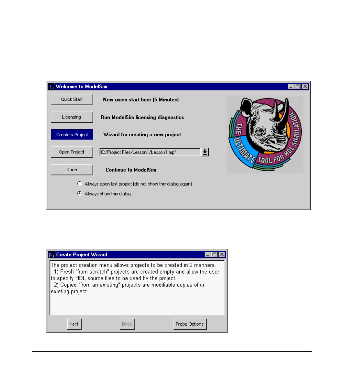
Creating a Project
1 To get started fast, select the Create a Project button from the Welcome to ModelSim
screen that opens the first time you start ModelSim 5.3. If this screen is not available,
you can enable it by selecting Help > Enable Welcome from the Main window.
Clicking the Create a Project button opens the Create a New Project dialog box
and a project creation wizard. The wizard guides you through each step of creating
a new project, helping you create and load the proj ect and provid ing the option of
entering Verilog or VHDL descriptions.
3-46 Projects and system initialization ModelSim EE/SE User’s Manual
Page 47

Creating a Project
Note: The Probe Options button allows you to probe the options within the Create a New Project dialog
box. The Create Project Wizard displays option information as the cursor moves over each feature.
The Create a New Project dialog box can also be accessed by sele cting File > New
> New Project from the ModelSim Main window.
In the Create a New Project dialog box, you can elect to create a new p roject from
scratch or copy an existing project.
If you select "create a new project from scratch," then:
2 Specify the "New Project’s Home," which is the directory under which this project’s
directory tree will reside.
3 Specify the "New Project’s Name," which will act as the project’s directory name. It
is recommended that a unique name be given to each project.
If you select "copy an existing project," then:
4 Specify an "Existing Project" name, which is the full path to an existing project’s .mpf
file.
ModelSim EE/SE User’s Manual Projects and system initialization 3-47
Page 48

Creating a Project
Note: A project’s MPF file is always located in the project’s directory.
Once you have specified enough information for the project creation. The OK
button is selectable. Selecting OK causes the project directory to be created with
a default working library. Once created the project is opened for use and the
project wizard prompts you for the entry of a HDL source file.
Entry of a HDL source file name opens an editor session on the empty file. The
source file must reside in the project’s directory tree. When the editor session is
complete you will be prompted to add the HDL source file to project’s source list.
This completes the process of creating a project. The project will be open for use
in the Main window. You can elect to leave ModelSim or edit the open project’s
HDL components until the project is completely specifed and all files compile into
libraries local to the project.
When you leave a ModelSim session, ModelSim will remember the last opened
project so it can be reopened for your next session by simply clicking Open
Project in the Welcome to ModelSim screen.
3-48 Projects and system initialization ModelSim EE/SE User’s Manual
Page 49

Working with a Project
Open a project
First, you must have a project open to work with it. To open a project select File
> Open > Open Project from the Main window (cd’ing into projects director y
won’t work).
Once you have opened a pr oject you can create HDL s ource files by selecting File
> New > New Source from the Main window. When you create HDL files in the
project’s root directory you are prompted to add them to the project . HDL files for
a given project must reside at or below the project’s root directory.
Compile a project
To compile your project’s HDL description with the project open, select Design >
Compile Project from the Main window, or click the Compile icon, and select the
files you want to compile. Each file will be compiled into your project’s work
library. Click Done when you are finished.
Working with a Project
Simulating a project
To simulate an open project, select Design > Load New Design from the Main
window or click th e Load Design ic on. On the Desi gn tab of this menu you specify
top level design unit for your project. On the VHDL and Verilog tabs you specify
HDL specific simulator settings (these are described in the VSIM portion of the
Reference Manual). On the SDF tab you can specify settings relating to the
annotation of design timing from an SDF file (optional).
Modifying a project
There are four types of project settings that can be modified, each is modified with
a different action..
1 Project-wide settings describe the make up of the project. These settings are changed
from the Options > Edit Project pull down menu.
2 Project compiler settings specify HDL compiler options. These settings are changed
from the Options > Compile pull down menu.
ModelSim EE/SE User’s Manual Projects and system initialization 3-49
Page 50

Working with a Project
3 Project design simulation settings describe how a specific design unit is loaded and
4 Project simulation settings describe simulation specific behavior. These set tings are
Using project settings with the command line tools
simulated. The simulation settings are edited from the Design > Load New Design
pull down menu or by clicking the Load Design icon.
edited from the Options > Simulation pull down me nu.
Project setting changes take place a different times. General Project editing
(Options > Edit_Project) is disabled while compiling or si mula ti ng and proj ectwide settings become effected after their change. Compiler option editing
(Options > Compile) is disabled while compiling and takes effect at the next
compile. Project design simulation settings (Design > Load New Design) take
effect at design load/reload. Simulation option edits (Options > Simulation) is
enabled during simulation and take effect immediately.
Generally, projects are used only within the ModelSim graphical user interface.
However, standalone tools will use the project file if they are invoked in the
project’s root directory. If invoked outside the project directory, th e MODELSIM
environment variable can be set with the path to the project file
(<Project_Root_Dir>/<Project_Name>.mpf).
The project command
The project command (CR-121) is used to perform common operations on new
projects. The command is to be used outside of a simulation session. See
"ModelSim Commands"
(CR-9) for complete command details.
3-50 Projects and system initialization ModelSim EE/SE User’s Manual
Page 51

4 - VHDL Simulation
Chapter contents
Compiling VHDL designs . . . . . . . . . . . . . . . . . 52
Creating a design library . . . . . . . . . . . . . . . .52
Invoking the VHDL compiler . . . . . . . . . . . . . . .52
Dependency checking . . . . . . . . . . . . . . . . .53
Simulating VHDL designs . . . . . . . . . . . . . . . . . 53
Invoking the simulator from the Main window. . . . . . . . . . . 53
Invoking Code Coverage with vsim . . . . . . . . . . . . .54
Using the TextIO package . . . . . . . . . . . . . . . . . 55
Syntax for file declaration . . . . . . . . . . . . . . . . 55
Using STD_INPUT and STD_OUTPUT within ModelSim . . . . . . .56
TextIO implementation issues . . . . . . . . . . . . . . . . 56
Writing strings and aggregates . . . . . . . . . . . . . . . 56
Reading and writing hexadecimal numbers . . . . . . . . . . . 57
Dangling pointers . . . . . . . . . . . . . . . . . . 57
The ENDLINE function . . . . . . . . . . . . . . . . 58
The ENDFILE function. . . . . . . . . . . . . . . . .58
Using alternative input/output files . . . . . . . . . . . . . . 58
Providing st imulus . . . . . . . . . . . . . . . . . . 58
Obtaining the VITAL specification and source code . . . . . . . . . .59
VITAL packages. . . . . . . . . . . . . . . . . . . . 59
ModelSim VITAL compliance . . . . . . . . . . . . . . . . 59
VITAL compliance checking . . . . . . . . . . . . . . .60
VITAL compliance warnings . . . . . . . . . . . . . . . 60
Compiling and Simulating with accelerated VITAL packages . . . . . . . . 61
This chapter provides an overview of compilation and simulation for VHDL
designs within the ModelSim/PLUS environment, using the TextIO package with
ModelSim, and ModelSim’s implementation of the VITAL (VHDL Initiative
Towards ASIC Libraries) specification for ASIC modeling.
The TextIO package is defined within the VHDL Language Reference Manuals,
IEEE Std 1076-1987 and IEEE Std 1076-1993; it allows human-readable text
input from a declared source within a VHDL file during simulation.
ModelSim EE/SE User’s Manual VHDL Simulation 4-51
Page 52

Compiling VHDL designs
Compiling and simulating with the GUI
Many of the examples in this chapter are shown from the command line. For
compiling and simulation within ModelSim’s GUI see:
• Compiling with the graphic interface
(10-244)
• Simulating with the graphic interface (10-251)
ModelSim variables
Several variables are available to control simulation, provide simulator state
feedback, or modify the appearance of the ModelSim GUI. To take effect, some
variables, such as environment variables, must be set prior to simulation. See
Appendix B - ModelSim Variables for a complete listing of ModelSim variables.
Compiling VHDL designs
Creating a design library
Before you can compile your design, you must create a library to store the
compilation results. Use vlib
vlib work
This creates a library named work. By default, compilation results are stored in
the work library.
Note: The work library is actually a subdirectory named work. This subdirectory contains a special file
named _info. Do not create libraries using UNIX, MS Windows, or DOS commands – always use the vlib
command (CR-198).
(CR-198) to create a new library. For example:
See "Design Libraries"
(2-31) for additional information on working with libraries.
Invoking the VHDL compiler
ModelSim compiles one or more VHDL design units with a single invocation of
vdel
(CR-175), the VHDL compiler. The design units are compiled in the order that
they appear on the command line. For VHDL, the order of compilation is
important – you must compile any entities or configurations before an architecture
that references them.
You can simulate a design containing units written with both the 1076 -1987 and
1076 -1993 versions of VHDL. To do so you will need to compile units from each
4-52 VHDL Simulation ModelSim EE/SE User’s Manual
Page 53

VHDL version separately. The vdel (CR-175) command compiles units written
with version 1076 -1987 by defa ult; use the -93 option with vdel
compile units written with version 1076 -1993. You can also change the default
by modifying the modelsim.ini file (see Chapter 3 - Projects and system
initialization for more information).
Dependency checking
Dependent design units must be rean alyzed when the design un its they d epend on
are changed in the library. vdel
compilation results have changed. For example, if you keep an entity and its
architectures in the same source file and you modify only an architecture and
recompile the source file, the entity compilation results will remain unchanged
and you will not have to recompile design units that depend on the entity.
Simulating VHDL designs
After compiling the design units, you can proceed to simulate your designs with
vsim
(CR-208). This section includes a discussi on of si mulation f rom the UN IX or
Windows/DOS command line. You can also use the graphic interface for
simulation, see "Simulating with the graphic interface"
Simulating VHDL designs
(CR-175) to
(CR-175) determines whether or not the
(10-251).
Note: Simulation normally stops if a failure occurs, however, if a bounds check on a signal fails the
simulator will continue running.
Invoking the simulator from the Main window
For VHDL, invoke vsim (CR-208) with the name of the configuration, or entity/
architecture pair. Note that if you specify a configuration you may not specify an
architecture.
This example invokes vsim
structure:
vsim my_asic structure
If a design unit name is not specified, vsim (CR-208) will present the Load Desi gn
dialog box from which you can choose a configuration or entity/architecture pair.
See "Simulating with the graphic interface"
ModelSim EE/SE User’s Manual VHDL Simulation 4-53
(CR-208) on the entity my_asic and the architecture
(10-251) for more information.
Page 54

Simulating VHDL designs
Selecting the time resolu tio n
The simulation time resolution is 1 ns by default. You can select a specific time
resolution with the vsim
Available resolutions are: 1x, 10x or 100x of fs, ps, ns, us, ms, or sec.
For example, to run in picosecond resolution, or 10ps resolution respectively:
vsim -t ps topmod
vsim -t 10ps topmod
The default time resolution can also be changed by modifying the resolution (B-
421)
report command
See "Projects and system initialization"
the modelsim.ini file.
vsim
with timing data from an SDF file. You can specify the min:typ:max delay by
invoking vsim
SDF file f1.sdf in the current work directory, the following invocation of vsim
208)
vsim -sdfmax /my_asic=f1.sdf
(CR-208) -t option or from the Load Design dialog box.
in the modelsim.ini file. You can view the current resolution by invoking the
(CR-131) with the simulat or state option.
(3-43) for more information on modify ing
(CR-208) is capable of annotating a design using VITAL compliant models
(CR-208) with the -sdfmin, -sdftyp and -sdfmax options. Using the
(CR-
annotates maximum timing values for the design unit my_asic:
Timing check disabling
By default, the timing checks within VITAL models are enabled. They are also
disabled with the +notimingchecks option.
For example:
vsim +notimingchecks topmod
Invoking Code Coverage with vsim
ModelSim’s Code Coverage feature gives you graphical and report fi le feeback on
how the source code is being executed. It allows line number execution statistics
to be kept by the simulator. It can be used during any design phase and in all levels
and types of designs. For complete details, see Chapter 8 - ModelSim SE Code
Coverage.
To acquire code coverage statistics, the -coverage s witch must be specifi ed during
the comman-line invocation of the simulator.
vsim -coverage
This will allow you to use the various code coverage commands: coverage clear
(CR-59), coverage reload (CR-60), and coverage report (CR-61).
4-54 VHDL Simulation ModelSim EE/SE User’s Manual
Page 55

Using the TextIO package
To access the routines in TextIO, include the following statement in your VHDL
source code:
USE std.textio.all;
A simple example using the package TextIO is:
USE std.textio.all;
ENTITY simple_textio IS
END;
ARCHITECTURE simple_behavior OF simple_textio IS
BEGIN
PROCESS
VARIABLE i: INTEGER:= 42;
VARIABLE LLL: LINE;
BEGIN
WRITE (LLL, i);
WRITELINE (OUTPUT, LLL);
WAIT;
END PROCESS;
END simple_behavior;
Using the TextIO package
Syntax for file declaration
The VHDL’87 syntax for a file declaration is:
identifier : subtype_indication is [ mode ] file_logical_name ;
file
where "file_logical_name" must be a string expression.
The VHDL’93 syntax for a file declaration is:
identifier_list : subtype_indication [ file_open_information ] ;
file
If a file is declared within an architecture, process, or package, the file is opened
when you start the simulator and is closed when you exit from it. If a file is
declared in a subprogram, the file is opened when the subprogram is called and
closed when execution RETURNs from the subprogram.
You can specify a full or relative path as the file_logical_name; for example
(VHDL’87):
file
filename : TEXT is in "usr/rick/myfile";
ModelSim EE/SE User’s Manual VHDL Simulation 4-55
Page 56

TextIO implementation issues
Using STD_INPUT and STD_OUTPUT within ModelSim
The standard VHDL’87 TextIO package contains the following file declarations:
file
input: TEXT is in "STD_INPUT";
file output: TEXT is out "STD_OUTPUT";
The standard VHDL’93 TextIO package contains these file declarations:
input: TEXT open read_mode is "STD_INPUT";
file
file output: TEXT open write_mode is "STD_OUTPUT";
STD_INPUT is a file_logical_name that refers to characters that are entered
interactively from the keyboard, and STD_OUTPUT refers to text that is
displayed on the screen.
In ModelSim reading from the STD_INPUT file brings up a d ialog box that allows
you to enter text into the current buffer. The last line written to the STD_OUTPUT
file appears as a prompt in this dialog box. Any text that is written to the
STD_OUTPUT file is also echoed in the Transcript window.
TextIO implementation issues
Writing strings and aggregates
A common error in VHDL source code occurs when a call to a WRITE procedure
does not specify whether the argument is of type STRI NG or BIT_VECTOR. For
example, the VHDL procedure:
WRITE (L, "hello");
will cause the following error:
ERROR: Subprogram "WRITE" is ambiguous.
In the TextIO package, the WRITE procedure is overloaded for the types STRING
and BIT_VECTOR. These lines are reproduced here:
procedure WRITE(L: inout LINE; VALUE: in BIT_VECTOR;
JUSTIFIED: in SIDE:= RIGHT; FIELD: in WIDTH := 0);
procedure WRITE(L: inout LINE; VALUE: in STRING;
JUSTIFIED: in SIDE:= RIGHT; FIELD: in WIDTH := 0);
The error occurs because the argument "hello" could be interpreted as a string or
a bit vector, but the compiler is not allowed to determine the argument type until
it knows which function is being called.
The following procedure call also generates an error:
WRITE (L, "010101");
4-56 VHDL Simulation ModelSim EE/SE User’s Manual
Page 57

This call is even more ambiguous, because the compiler could not determine, even
if allowed to, whether the argument "010101" should be interpreted as a string or
a bit vector.
There are two possible solutions to this problem:
• Use a qualified expression to specify the type, as in:
WRITE (L, string’("hello"));
• Call a procedure that is not overloaded, as in:
WRITE_STRING (L, "hello");
The WRITE_STRING procedure simply defines the value to be a STRING and
calls the WRITE procedure, but it serves as a shell around the WRITE procedure
that solves the overloading problem. For further details, refer to the
WRITE_STRING procedure in the io_utils package, which is located in the file
io_utils.vhd.
Reading and writing hexadecimal numbers
The reading and writing of hexadecimal numbers is not specified in standard
VHDL. The Issues Screening and Analysis Committee of the VHDL Analysis and
Standardization Group (ISAC-VASG) has specified that the TextIO package
reads and writes only decimal numbers.
TextIO implementation issues
To expand this functionality, ModelSim supplies hexadecim a l r outines in the
package io_utils, which is located in the file io_utils.vhd. To use these routines,
compile the io_utils package and then include the following use clauses in your
VHDL source code:
use std.textio.all;
use work.io_utils.all;
Dangling pointers
Dangling pointers are easily incurred when using the TextIO package, because
WRITELINE deallocates the access type (pointer) that is passed to it. Following
are examples of good and bad VHDL coding styles:
Bad VHDL (because L1 and L2 both point to the same buffer):
READLINE (infile, L1); -- Read and allocate buffer
L2 := L1; -- Copy pointers
WRITELINE (outfile, L1); -- Deallocate buffer
Good VHDL (because L1 and L2 point to different buffers):
READLINE (infile, L1); -- Read and allocate buffer
L2 := new string’(L1.all); -- Copy contents
WRITELINE (outfile, L1); -- Deallocate buffer
ModelSim EE/SE User’s Manual VHDL Simulation 4-57
Page 58

TextIO implementation issues
The ENDLINE function
The ENDLINE function described in the IEEE Standard VHDL Language
Reference Manual, IEEE Std 1076-1987 contains invalid VHDL syntax and
cannot be implemented in VHDL. This is because access types must be passed as
variables, but functions only allow constant parameters.
Based on an ISAC-VASG recommendation the ENDLINE function has been
removed from the TextIO package. The following test may be substituted for this
function:
(L = NULL) OR (L’LENGTH = 0)
The ENDFILE function
In the VHDL Language Reference Manuals, IEEE Std 1076-1987 and IEEE Std
1076-1993, the ENDFILE function is listed as:
-- function ENDFILE (L: in TEXT) return BOOLEAN;
As you can see, this function is commented out of the standard TextIO package.
This is because the ENDFILE function is implicitly declared, so it can be used
with files of any type, not just files of type TEXT.
Using alternative input/output files
You can use the TextIO package to read and write to your own files. To do this,
just declare an input or output file of type TEXT.
The VHDL’87 declaration is:
file
myinput : TEXT is in "pathname.dat";
For VHDL’93 the declaration is:
myinput : TEXT open read_mode is "pathname.dat";
file
Then include the identifier for this file ("myinput" in this example) in the
READLINE or WRITELINE procedure call.
Providing stimulus
You can create batch files containing force (CR-87) commands that provide
stimulus for simulation. A VHDL test bench has been included with the ModelSim
install files as an example; it illustrates how results can be genera ted by reading
vectors from a file. Check for this file:
<install_dir>/modeltech/examples/stimulus.vhd
4-58 VHDL Simulation ModelSim EE/SE User’s Manual
Page 59

Obtaining the VITAL specification and source code
Obtaining the VITAL specification and source code
VITAL ASIC Modeling Specification
The IEEE 1076.4 VITAL ASIC Modeling Specification is available from the
Institute of Electrical and Electronics Engineers, Inc.:
IEEE Customer Service
Hoes Lane
Tiscataway, NJ 08855-1331
Tel: (800)678-4333 ((908)562-5420 from outside the U.S.)
Fax: (908)981-9667
home page: http://www.ieee.org
VITAL source code
The source code for VITAL packages is provided in the /<install_dir>/
modeltech/vhdl_src/vital2.2b, or /vital95 directories.
VITAL packages
VITAL v3.0 accelerated packages are pre-compiled into the ieee library in the
installation directory.
Note: By default, ModelSim is optimized for VITAL v3.0. You can, however, revert to VITAL v2.2b by
invoking vsim (CR-208) with the -vital2.2b option, and by mapping library vital to <install_dir>/vital2.2b.
ModelSim VITAL compliance
A simulator is VITAL compliant if it implements the SDF mapping and if it
correctly simulates designs using the VITAL packages, as outlined in the VITAL
Model Development Specification. ModelSim VSIM is compliant with the IEEE
1076.4 VITAL ASIC Modeling Specification. In addition, ModelSim accelerates
the VITAL_Timing and VITAL_Primitives packages. The procedures in these
packages are optimized and built into the simulator kernel. By default, vsim
uses the optimized procedures. The optimized procedures are functionally
208)
equivalent to the IEEE 1076.4 VITAL ASIC Modeling Specification (VITAL
v3.0).
ModelSim EE/SE User’s Manual VHDL Simulation 4-59
(CR-
Page 60

ModelSim VITAL compliance
VITAL compliance checking
Compliance checking is important in enabling VITAL acceleration; to q ualify for
global acceleration, an architecture must be VITAL-level-one compliant. vdel
(CR-175) automatically checks for VITAL 3.0 compliance on all entities with the
VITAL_Level0 attribute set, and all architectures with the VITAL_Level0 or
VITAL_Level1 attribute set.
If you are using VITAL 2.2b, you must turn off the compliance checking either by
not setting the attributes, or by invoking vdel
-novitalcheck. It is, of course, possible to turn off compliance checking for
VITAL 3.0 as well; we strongly suggest that you leave checking on to ensure
optimal simulation.
VITAL compliance warnings
The following LRM errors are printed as warnings (if they were con sidered errors
they would prevent VITAL level 1 acceleration); they do not affect how the
architecture behaves.
• Starting index constraint to DataIn and PreviousDataIn parameters to
• Size of PreviousDataIn parameter is larger then the size of the DataIn parameter
(CR-175) with the option
VITALStateTable do not match (1076.4 section 6.4.3.2.2)
to VITALStateTable (1076.4 section 6.4.3.2.2)
• Signal q_w is read by the VITAL process but is NOT in the sensitivity list
(1076.4 section 6.4.3)
The first two warnings are minor cas es where the bod y of the VITAL 3.0 LR M is
slightly stricter then the package portion of the LRM. Since either interpretation
will provide the same simulation results, we chose to make these two cases just
warnings.
The last warning is a relaxation of the restriction on reading an internal signal that
is not in the sensitivity list. This is relaxed only for the CheckEnabled parameters
of the timing checks, and only if it is not read elsewhere.
You cannot control the visibility of VITAL compliance-check warnings in your
vdel
(CR-175) transcript. They can be suppressed by using the vcom -nowarn
switch as in vcom -nowarn 6. The 6 comes from the warning level printed as part
of the warning, i.e., WARNING[6]. You can also add the following line to your
modelsim.ini file in the [vcom] VHDL compiler control variables
[vcom]
Show_VitalChecksWarnings = 0
(B-395) section.
4-60 VHDL Simulation ModelSim EE/SE User’s Manual
Page 61

Compiling and Simulating with accelerated VITAL packages
Compiling and Simulating with accelerated VITAL packages
vdel (CR-175) automatically recognizes that a VITAL function is being referenced
from the ieee library and generates code to call the optimized built-in routines.
Optimization occurs on two levels:
• VITAL Level-0 optimization
This is a function-by-function optimization. It applies to all level-0
architectures, and any level-1 architectures that failed level-1 optimization.
• VITAL Level-1 optimization
Performs global optimization on a VITAL 3.0 level-1 architecture that passes
the VITAL compliance checker. This is the default behavior.
Compiler options for VITAL optimization
Several vdel
(CR-175) options control and provide feedback on VITAL
optimization:
-O0 | -O4
Lower the optimization to a minimum with -O0 (capital oh zero). Optional. Use this to
work around bugs, increase your debu gging vis ibility on a specific cell, or when you want
to place breakpoints on source lines that have been optimized out.
Enable optimizations with -O4 (default).
-debugVA
Prints a confirmation if a VITAL cell was optimized, or an explanation of why it was not,
during VITAL level-1 acceleration.
ModelSim VITAL built-ins will be updated in step with new releases of the
VITAL packages.
ModelSim EE/SE User’s Manual VHDL Simulation 4-61
Page 62

4-62 VHDL Simulation ModelSim EE/SE User’s Manual
Page 63

5 - Verilog Simulation
Chapter contents
Compilation . . . . . . . . . . . . . . . . . . . . .65
Incremental compilation . . . . . . . . . . . . . . . . 66
Library usage . . . . . . . . . . . . . . . . . . . 68
Verilog-XL compatible compiler options . . . . . . . . . . . .70
Verilog-XL ‘uselib compiler directive . . . . . . . . . . . . .72
Simulation . . . . . . . . . . . . . . . . . . . . . 74
Invoking the simulator . . . . . . . . . . . . . . . . . 75
Simulation resolution limit . . . . . . . . . . . . . . . .75
Event order issues . . . . . . . . . . . . . . . . . .76
Verilog-XL compatible simulator options . . . . . . . . . . . . 78
Cell Libraries . . . . . . . . . . . . . . . . . . . . 80
SDF timing annotation . . . . . . . . . . . . . . . . . 81
Delay modes . . . . . . . . . . . . . . . . . . . 81
System Tasks . . . . . . . . . . . . . . . . . . . .82
IEEE Std 1364-1995 system tasks . . . . . . . . . . . . . . 82
Verilog-XL compatible system tasks . . . . . . . . . . . . . 85
Compiler Directives . . . . . . . . . . . . . . . . . . . 87
IEEE Std 1364-1995 compiler directives . . . . . . . . . . . . 88
Verilog-XL compatible compiler directives . . . . . . . . . . . 89
Using the Verilog PLI . . . . . . . . . . . . . . . . . .90
Registering PLI applications . . . . . . . . . . . . . . .90
Compiling and linking PLI applications . . . . . . . . . . . . 92
The callback reason argument . . . . . . . . . . . . . . . 97
The sizetf callback function. . . . . . . . . . . . . . . . 99
Object handles . . . . . . . . . . . . . . . . . . . 99
Third party PLI applications . . . . . . . . . . . . . . . 99
Support for VHDL objects . . . . . . . . . . . . . . . 100
IEEE Std 1364 ACC routines . . . . . . . . . . . . . . 101
IEEE Std 1364 TF routines . . . . . . . . . . . . . . . 103
Verilog-XL compatible routines . . . . . . . . . . . . . 104
PLI tracing . . . . . . . . . . . . . . . . . . . 105
ModelSim EE/SE User’s Manual Verilog Simulation 5-63
Page 64

This chapter describes how to compile and simulate Verilog designs with
ModelSim Verilog. ModelSim Verilog implements the Verilog language as
defined by the IEEE Std 1364-1995, and it is recommended that you obtain this
specification as a reference manual.
In addition to the functionality described in the IEEE Std 1364-1995, ModelSim
Verilog includes the following features:
• Standard Delay Format (SDF) annotator compatible with many ASIC and
FPGA vendor's Verilog libraries.
• Value Change Dump (VCD) file extensions for ASIC vendor test tools.
• Dynamic loading of PLI applications.
• Compilation into retargetable, executable code.
• Incremental design compilation.
• Extensive support for mix ing VHDL and Veril og in the same desi gn (includi ng
SDF annotation).
• Graphic Interface that is common with ModelSim VHDL.
• Extensions to provide compatibility with Verilog-XL.
The following IEEE Std 1364-1995 functionality is not implem ented in ModelSim
Verilog:
• Array of instances (see section 7.1.5 in the IEEE Std 1364-1995).
• Verilog Procedural Interface (VPI) (see sections 22 and 23 in the IEEE Std
1364-1995).
• Macros (compiler `define directives) with arguments.
Many of the examples in this chapter are shown from the command line. For
compiling and simulation within ModelSim’s GUI see:
• Compiling with the graphic interface
• Simulating with the graphic interface (10-251)
(10-244)
ModelSim variables
Several variables are available to control simulation, provide simulator state
feedback, or modify the appearance of the ModelSim GUI. To take effect, some
variables, such as environment variables, must be set prior to simulation. See
Appendix B - ModelSim Variables for a complete listing of ModelSim variables.
5-64 Verilog Simulation ModelSim EE/SE User’s Manual
Page 65

Compilation
Before you can simulate a Verilog design, you must first create a library and
compile the Verilog source code into that library. This section provides detailed
information on compiling Verilog designs. For information on creating a design
library, see Chapter 2 - Design Libraries.
ModelSim Verilog compiles Verilog source code into retargetable, executable
code, meaning that the library format is compatib le across all supported platfo rms
and that you can simulate your design on any platform without having to
recompile your design specificall y for that platform. As you com pile your design,
the resulting object code for modules and UDPs is generated into a library. By
default, the compiler places results into the work library. You may specify an
alternate library with the -work option. The following is a simple examp le of how
to create a work library, compile a design, and simulate it:
Contents of top.v:
module top;
initial $display("Hello world");
endmodule
Create the work library:
% vlib work
Compilation
Compile the design:
% vlog top.v
-- Compiling module top
Top level modules:
top
View the contents of the work library (optional):
% vdir
MODULE top
Simulate the design:
% vsim -c top
# Loading work.top
VSIM 1> run -all
# Hello world
VSIM 2> quit
ModelSim EE/SE User’s Manual Verilog Simulation 5-65
Page 66

Compilation
In this example, the simulator was run without the graphic interface by specifying
the -c option. After the design was loaded, the simulator command run -all was
entered, meaning to simulate until there are no more simulator events. Finally, the
quit command was entered to exit the simulator. By default, a log of the simulation
is written to the file "transcript" in the current directory.
Incremental compilation
By default, ModelSim Verilog supports incremental compilation of designs, thus
saving compilation time when you modify your design. Unlike other Verilog
simulators, there is no requirement that you compile the entire design in one
invocation of the compiler (although, you may do so if desired).
You are not required to compile your design in any particular order because all
module and UDP instantiations and external hierarchical references are resolved
when the design is loaded by the simulator. Incremental compilation is made
possible by deferring these bindings, and as a result some errors cannot be
detected during compilation. Commonly, these errors include: modules that were
referenced but not compiled, incorre ct port connections, and incorrect hierar chical
references.
The following example shows how a hierarchical design can be compiled in top
down order:
Contents of top.v:
module top;
or2(n1, a, b);
and2(n2, n1, c);
endmodule
Contents of and2.v:
module and2(y, a, b);
output y;
input a, b;
and(y, a, b);
endmodule
Contents of or2.v:
module or2(y, a, b);
output y;
input a, b;
or(y, a, b);
endmodule
5-66 Verilog Simulation ModelSim EE/SE User’s Manual
Page 67

Compile the design in top down order (assumes work library already exists):
% vlog top.v
-- Compiling module top
Top level modules:
top
% vlog and2.v
-- Compiling module and2
Top level modules:
and2
% vlog or2.v
-- Compiling module or2
Top level modules:
or2
Note that the compiler lists each module as a top level module, although,
ultimately, only "top" is a top level module. If a module is not referenced by
another module compiled in the same invocation of the compiler, then it is listed
as a top level module. This is just an informative message and can be ignored
during incremental compilation. The message is more useful when you compile
an entire design in one invocation of the compiler and need to know the top level
module names for the simulator. For example,
% vlog top.v and2.v or2.v
-- Compiling module top
-- Compiling module and2
-- Compiling module or2
Compilation
Top level modules:
top
The most efficient method of incremental compilation is to manually compile only
the modules that have changed. This is not always convenient, especially if your
source files have compiler directive interdependencies (such as macros). In this
case, you may prefer to always compile yo ur entire design in one invocation of the
compiler. If you specify the -incr option, the compiler will automatically
determine which modules have changed and generate code only for those
modules. This is not as efficient as manual incremental compilation because the
compiler must scan all of the source code to determine which modules must be
compiled.
ModelSim EE/SE User’s Manual Verilog Simulation 5-67
Page 68

Compilation
The following is an example of how to compile a design with automatic
incremental compilation:
% vlog -incr top.v and2.v or2.v
-- Compiling module top
-- Compiling module and2
-- Compiling module or2
Top level modules:
top
Now, suppose that you modify the functionality of the "or2" module:
% vlog -incr top.v and2.v or2.v
-- Skipping module top
-- Skipping module and2
-- Compiling module or2
Top level modules:
top
The compiler informs you that it skipped the modules "top" and "and2", and
compiled "or2".
Automatic incremental compilation is intelligent about when to compile a module.
For example, adding a comment to your source code does not result in a
recompile; however, changing the compiler command line options results in a
recompile of all modules.
Library usage
All modules and UDPs in a Verilog design must be compiled into one or more
libraries. One library is usually sufficient for a simple design, but you may want
to organize your modules into various libraries for a complex design. If your
design uses different modules havi ng the same n ame, then you are required to p ut
those modules in different libraries because design unit names must be unique
within a library.
The following is an example of how you may organize your ASIC cells into one
library and the rest of your design into another:
% vlib work
% vlib asiclib
% vlog -work asiclib and2.v or2.v
-- Compiling module and2
-- Compiling module or2
5-68 Verilog Simulation ModelSim EE/SE User’s Manual
Page 69

Top level modules:
and2
or2
% vlog top.v
-- Compiling module top
Top level modules:
top
Note that the first compilation uses the -work asiclib option to instruct the
compiler to place the results in the asiclib library rather than the default work
library.
Since instantiation bindings are not determined at co mpile time, you must instru ct
the simulator to search your libraries when loading the design. The top level
modules are loaded from the library named work unless you specify an alternate
library with the -lib option. All other Verilog instantiations are resolved in the
following order:
• Search libraries specified with -Lf options in the order they appear on the
command line.
Compilation
• Search the library specified in "Verilog-XL `uselib compiler directive"
(5-72).
• Search libraries specified with -L options in the order they appear on the
command line.
• Search the work library.
• Search the library explicitly named in the special escaped identifier instance
name.
It is important to recognize that the work library is not necessarily a library named
work - the work library refers to the library containing the module that
instantiates the module or UDP that is currently being searched for. This definition
is useful if you have hi erar chi cal mo dul es or gani zed int o se par ate lib rarie s and if
sub-module names overlap among the libraries. In this situation you want the
modules to search for their sub-modules in the work library first. This is
accomplished by specifying -L work first in the list of search libraries.
For example, assume you have a top level module "top" that instantiates module
"modA" from library "libA" and module "modB" from library "libB".
Furthermore, "modA" and "modB" both instantiate modules named "cellA", but
the definition of "cellA" compiled into "libA" is different from that compiled into
"libB". In this case, it is insufficient to just specify "-L libA - LlibB" as the search
libraries because instantiations of "cellA" from "modB" resolve to the "libA"
version of "cellA". The appropriate search library options are "-L work -L libA
-L libB".
ModelSim EE/SE User’s Manual Verilog Simulation 5-69
Page 70

Compilation
Verilog-XL compatible comp iler options
See vlog (CR-199) for a complete list of compile r options. The options described
here are equivalent to Verilog-XL options. Many of these are provided to ease the
porting of a design to ModelSim Verilog.
+define+<macro_name>[=<macro_text>]
This option allows you to define a macro from the command line that is equivalent
to the following compiler directive:
‘define <macro_name> <macro_text>
Multiple +define options are allowed on the command line. A command line
macro overrides a macro of the same name defined with the ‘define compiler
directive.
+incdir+<directory>
This option specifies directories to search for files included with ‘include
compiler directives. By default, the current directory is searched first and then the
directories specified by the +incdir options in the order they appear on the
command line. You may specify multiple +incdir options as well as multiple
directories separated by "+" in a single +incdir option.
+delay_mode_distributed
This option disables path delays in favor of distributed delays. See Delay modes
(5-81) for details.
+delay_mode_path
This option sets distributed delays to zero in favor of path delays. See Delay
modes
(5-81) for details.
+delay_mode_unit
This option sets path delays to zero and non-zero distributed delays to one time
unit. See Delay modes
+delay_mode_zero
(5-81) for detail s.
This option sets path del ays and distribute d delays to zero. See Del ay modes (5-81)
for details.
-f <filename>
This option reads more command line arguments from the specified text file.
Nesting of -f options is allowed.
5-70 Verilog Simulation ModelSim EE/SE User’s Manual
Page 71

Compilation
+mindelays
This option selects minimum delays from the "min:typ:max" expressions. If
preferred, you may defer delay selection until simulation time by specifying the
same option on the simulator.
+typdelays
This option selects typical delays from the "min:typ:max" expressions. If
preferred, you may defer delay selection until simulation time by specifying the
same option on the simulator.
+maxdelays
This option selects maximum delays from the "min:typ:max" expressions. If
preferred, you may defer delay selection until simulation time by specifying the
same option on the simulator.
-u
This option treats all identifiers in the source code as all uppercase.
The following options support source libraries in the same manner as Verilog-XL.
Note that these libraries are source libraries and are very different from the libraries
that the ModelSim compiler uses to store compilation results. You may find it
convenient to use these options if you are porting a design to ModelSim or if you are
familiar with these options and prefer to use them.
Source libraries are searched after the source files on the command line are compiled.
If there are any unresolved references to module s or UDPs, then the compiler searches
the source libraries to satisfy them. The modules compiled from source libraries may
in turn have additional unresolved references that cause the source libraries to be
searched again. This process is repeated until all references are resolved or until no
new unresolved references are found. Source libraries are searched in the order they
appear on the command line.
-v <filename>
This option specifies a source library file containing module and UDP definitions.
Modules and UDPs within the file are compiled only if they match previously
unresolved references. Multiple -v options are allowed.
-y <directory>
This option specifies a source library directory containing module and UDP
definitions. Files within this directory are compiled only if the file names m atch
the names of previously unresolved references. Multiple -y options are allowed.
ModelSim EE/SE User’s Manual Verilog Simulation 5-71
Page 72

Compilation
+libext+<suffix>
This option works in conjunction with the -y option. It specifies file extensions for
the files in a source library directory. By default the compiler searches for files
without extensions. If you specify the +libext option, then the compiler will
search for a file with the suffix appended to an unresolved nam e. You may specify
only one +libext option, but it may contain multiple suffixes separated by "+". The
extensions are tried in the order they appear in the +libext option.
+librescan
This option changes how unresolved references are handled that are added while
compiling a module or UDP from a source library. By default, the compiler
attempts to resolve these references as it continues searching the source libraries.
If you specify the +librescan option, then the new unresolved references are
deferred until after the current pass through the source libraries. They are then
resolved by searching the source libraries from the beginnin g in the order they are
specified on the command line.
+nolibcell
By default, all modules compiled from a source library are treated as thou gh they
contain a ‘celldefine compiler directive. This option disables this default. The
‘celldefine directive only affects the PLI Access routines acc_next_cell and
acc_next_cell_load.
The -R option is not a Verilog-XL option, but it is used by ModelSim Verilog to
combine the compile and simulate phases together as you may be used to with VerilogXL. It is not recommended that you regularly use this option because you will incur
the unnecessary overhead of comp iling your design for each simulation run. Mainly , it
is provided to ease the transition to ModelSim Verilog.
-R <simargs>
This option instructs the compiler to invoke the simulator after compiling the
design. The compiler automatically determines which top level modules are to be
simulated. The command line arguments following -R are passed to the simulator,
not the compiler. Place the -R option at the end of the command lin e or ter minate
the simulator command line arguments with a si ngle "-" character to differentiate
them from compiler command line arguments.
Verilog-XL ‘uselib compiler directive
The ‘uselib compiler directive is an alternative source library management
scheme to the -v, -y, and +libext compiler options. It has the advantage that a
design may reference different modules having the same name. The ‘uselib
compiler directive is not defined in the IEEE Std 1364-1995, but ModelSim
supports it for compatability with Verilog-XL.
5-72 Verilog Simulation ModelSim EE/SE User’s Manual
Page 73

Compilation
The syntax for the ‘uselib directive is:
‘uselib <library_reference>...
where <library_reference> is:
dir=<library_directory> | file=<library_file> | libext=<file_extension> |
lib=<library_name>
In Verilog-XL, the library references are equivalent to command line options as
follows:
dir=<library_directory> -y <library_directory>
file=<library_file> -v <library_file>
libext=<file_extension> +libext+<file_extension>
For example, the following directive
‘uselib dir=/h/vendorA libext=.v
is equivalant to the following command line options:
-y /h/vendorA +libext+.v
Since the ‘uselib directives are embedded in the Verilog source code, there is
more flexibility in defining the source libraries for the instantiations in the design.
The appearance of a ‘uselib directive in the source code explicitly defines how
instantiations that follow it are resolved, completely overriding any previous
‘uselib directives.
For example, the following code fragment shows ho w two different modules that
have the same name can be instantiated within the same design:
‘uselib dir=/h/vendorA file=.v
NAND2 u1(n1, n2, n3);
‘uselib dir=/h/vendorB file=.v
NAND2 u2(n4, n5, n6);
This allows the NAND2 module to have different definitions in the vendorA and
vendorB libraries.
ModelSim Verilog supports the ‘uselib directive in a different manner than
Verilog-XL. The library files referenced by the ‘uselib directive are not
automatically compiled by ModelSim Verilog. The reas on for this is that an object
library is not allowed to contain multiple modules having the same name, and the
results of a single invocation of the compiler can be placed in only one object
library. Because it is an important feature of ‘uselib to allow a design to reference
multiple modules having the same name, independent compilation of the source
libraries referenced by the ‘uselib directives is required. Each source library
ModelSim EE/SE User’s Manual Verilog Simulation 5-73
Page 74

Simulation
should be compiled into its own object library. The compilation of the code
containing the ‘uselib directives only records which object libraries to search fo r
each module instantiation when the design is loaded by the simulator.
Because the ‘uselib directive is intended to reference source libraries, ModelSim
Verilog must infer the object libraries from the library references. The rule is to
assume an object library named work in the directory defined in the library
reference dir=<library_directory> or the directory containing the file in the
library reference file=<library_file>. The library reference
libext=<file_extension> is ignored. For example, the following ‘uselib directives
infer the same object library:
‘uselib dir=/h/vendorA
‘uselib file=/h/vendorA/libcells.v
In both cases ModelSim Verilog assumes that the library source is compiled into
the object library /h/vendorA/work.
ModelSim Verilog also extends the ‘uselib directive to explicitly specify the
object library with the library reference lib=<library_name>. For example,
‘uselib lib=/h/vendorA/work
The library name can be a complete path to a library, or it can be a logical lib rary
name defined with the vmap command. Since this usage of ‘uselib is an
extension, it may be desirable to qualify it with an ‘ifdef to make it portable to
other Verilog systems. For example,
‘ifdef MODEL_TECH
‘uselib lib=vendorA
‘else
‘uselib dir=/h/vendorA libext=.v
‘endif
The MODEL_TECH macro is automatically defined by the ModelSim compiler.
Simulation
The ModelSim simulator can load and simulate both Verilog and VHDL designs,
providing a uniform graphic interface and simulation control commands for
debugging and analyzing your designs. The graphic interface and simulator
commands are described elsewhere in this manual, while this section focuses
specifically on Verilog simulation.
5-74 Verilog Simulation ModelSim EE/SE User’s Manual
Page 75

Invoking the simulator
A Verilog design is ready for simulation after it has been compiled into one or
more libraries. The simulator may then be invoked with the names of the top level
modules (many designs con tain o nly on e top level module). For example, if your
top level modules are "testbench" and "globals", then invoke the simulator as
follows:
vsim testbench globals
If a top-level module name is not specified, VSIM will present the Load Design
dialog box from which you can choose one or more top-level modules. See
"Simulating with the graphic interface"
After the simulator loads the top level modules, it iteratively loads the instantiated
modules and UDPs in the design hierarchy, linking the design together by
connecting up the ports and resolving hierarchical references. By default, all
modules and UDPs are loaded from the library named work.
On successful loading of the design, the simulation time is set to zero, and you
must enter a run command to begin simulati on. Commonly , you enter run -all to
run until there are no more simulation events or until $finish is executed in the
Verilog code. You may also run for specific time periods, i.e., run 100 ns. Enter
the quit command to exit the simulator.
Simulation
(10-251) for more information.
Simulation resolution limit
The simulator internally represents time as a 64-bit integer in units equivalent to
the smallest unit of simulation time, also known as the simulation resolution limit.
The resolution limit defaults to the smallest time precision found among all of the
‘timescale compiler directives in the design. The time precision is the second
number in the ‘timescale directive. For example, "10 ps" in the following:
‘timescale 1 ns / 10 ps
The time precision should not be unnecessarily small because it will limit the
maximum simulation time limit, and it will degrade performance in some cases.
If the design co ntains no ‘timescale directives, then the resolution limit defaults to
the "resolution" value specified in the modelsim.ini file (default is 1 ns). In any
case, you may override the default resolution limit by specifying the -t option on
the command line.
For example, to explicitly choose 100 ps resolution:
vsim -t 100ps top
ModelSim EE/SE User’s Manual Verilog Simulation 5-75
Page 76

Simulation
This forces 100 ps resolution even i f the des i gn co ntai ns sm aller t ime precisions .
As a result, time values with finer precision are rounded to the nearest 100 ps.
Event order issues
The Verilog language is defined such that the simulator is not required to execute
simultaneous events in any particular order. Unfortunately, some models are
inadvertently written to rely on a particular event order, and these models may
behave differently when port ed to another Veril og simulator . A model with event
order dependencies is ambiguous and should be corrected. For example, the
following code is ambiguous:
module top;
reg r;
initial r = 0;
initial r = 1;
initial #10 $display(r);
endmodule
The value displayed for "r" depends on the order that the simulator executes the
initial constructs that assign to "r". Conceptually, the initial constructs run
concurrently and the simulator is allowed to execute them in any order. ModelSim
Verilog executes the initial constructs in the order they appear in the module, and
the value displayed for "r" is "1". Verilog-XL produces the same result, but a
simulator that displays "0" is not incorrect because the code is ambiguous.
Since many models have been developed on Verilog-XL, ModelSim Verilog
duplicates Verilog-XL event ordering as much as possible to ease the porting of
those models to ModelSim Verilog. However, ModelSim Verilog does not match
Verilog-XL event ordering in all cases, and if a model ported to ModelSim Verilog
does not behave as expected, then you should suspect that there are event order
dependencies.
Tracking down event order dependencies is a tedious task, so ModelSim Verilog
aids you with a couple of compiler options:
-compat
This option turns off optimizations that result in different event ordering than
Verilog-XL. ModelSim Verilog generally duplicates Verilo g-XL event ord eri ng ,
but there are caseswhere it is inefficient to do so. Using this option does not help
you find the event order dependencies, but it allows you to ignore them. Keep in
mind that this option does not account for all event order discrepancies, and that
using this o ption may degrade performance.
5-76 Verilog Simulation ModelSim EE/SE User’s Manual
Page 77

-hazards
This option detects event order hazards involving simultaneous reading and
writing of the same register in concurrently executing processes. To enable hazard
detection you must invoke vlog
compile your source code and you must also invoke vsim
(CR-199) with the -hazards option when you
(CR-208) with the
-hazards option when you simulate.
The vsim command
(CR-208) detects the following kinds of hazards:
• WRITE/WRITE:
Two processes writing to the same variable at the same time.
• READ/WRITE:
One process reading a variable at the same time it is b eing written to by an other
process. VSIM calls this a READ/WRITE hazard if it executed the read first.
• WRITE/READ:
Same as a READ/WRITE hazard except that VSIM executed the write first.
The vsim command
(CR-208) issues an error message when it detects a hazard. The
message pinpoints the variable and the two processes involved. You can have the
simulator break on the statement where the hazard is detected by setting the break
on assertion level to error.
Simulation
To enable hazard detection you must invoke vlog
option when you compile your source code and you must also invoke vsim
with the -hazards option when you simulate.
208)
(CR-199) with the -hazards
(CR-
Limitations of hazard detection:
• Reads and writes involving bit and part selects of vectors are not considered fo r
hazard detection. The overhead of tracking the overlap between the bit and p art
selects is too high.
• A WRITE/WRITE hazard is flagged even if the same value is written by both
processes.
• A WRITE/READ or READ/WRITE hazard is flagged even if the write does not
modify the variable's value.
• Glitches on nets caused by non-guaranteed event ordering are not detected.
ModelSim EE/SE User’s Manual Verilog Simulation 5-77
Page 78

Simulation
Verilog-XL compatible simulator options
See vsim (CR-208) for a complete list of simulator options. The options described
here are equivalent to Verilog-XL options. Many of these are provided to ease the
porting of a design to ModelSim Verilog.
+alt_path_delays
Specify path delays operate in inertial mode by default. In inertial mode, a pending
output transition is cancelled before a new output transition is scheduled, and the
delay is selected based on the transition from the current value of the net to the
new pending value. The result is that an output may have no more than one
pending transition at a time, and that pulses narrower than the delay are filtered.
The +alt_path_delays option modifies the inertial mode such that a delay is based
on a transition from a pending output value rather than the current value of the net.
This option has no effect in transp ort mode (se e +pulse_e
).
79)
-l <filename>
By default, the simulation log is written to the file "transcript". The -l option
allows you to specify an alternate file.
+maxdelays
This option selects the maximum value in min:typ:max expressions. The default
is the typical value. This option has no effect if the min:typ:max selection was
determined at compile time.
(5-79) and +pulse_r (5-
+mindelays
This option selects the minimum value in min:typ:max express ions. The default is
the typical value. This option has no effect if the min:typ:max selection was
determined at compile time.
+no_notifier
This option disables the toggling of the notifier register argument of the timing
check system tasks. By default, the notifier is to ggled when there is a timing check
violation, and the notifier usually causes a UDP to propagate an X. Ther efore, the
+no_notifier option suppresses X propagation on timing violations.
+no_pulse_msg
This option disables the warning message for specify path pulse errors. A path
pulse error occurs when a pulse propagated through a path delay falls between the
pulse rejection limit and pulse error limits set with the +pulse_r and +pulse_e
options. A path pulse error results in a warning message, and the pulse is
progagated as an X. The +no_pulse_msg option disables the warning message,
but the X is still propagated.
5-78 Verilog Simulation ModelSim EE/SE User’s Manual
Page 79

+no_tchk_msg
This option disables error messages issued by timing check system tasks when
timing check violations occur. However, notifier registers are still toggled any
may result in the propagation of X’s for timing check violations.
+nosdfwarn
This option disables warning messages during SDF annotation.
+notimingchecks
This option completely disables all timing check system tasks.
+nowarn<mnemonic>
This option disables the class of warning messages specified by <mnemonic>.
This option only disables warning messages accompanied by a mnemonic
enclosed in square brackets. For example,
# WARNING: test.v(2): [TFMPC] - Too few port connections.
This warning message can be disabled with the +nowarnTFMPC option.
+pulse_e/<percent>
This option controls how pulses are propagated through specify path delays,
where <percent> is a number between 0 and 100 that s pecifies the error limit as a
percentage of the path delay. A pulse greater than or equal to the error limit
propagates to the output in transport mode (transport mode allows multiple
pending transitions on an output). A pulse less than the error limit and gre ater than
or equal to the rejection limit (see +pulse_r
(5-79)) propagates to the output as an
X. If the rejection limit is not specified, then it defaults to the error limit. For
example, consider a path delay of 10 along with a +pulse_e/80 option. The error
limit is 80% of 10 and the rejection limit defaults to 80% of 10. This results in the
propagation of pulses greater than or equal to 8, while all other pulses are filtered.
Note that you can forcespecify path delays to operate i n trans por t mode by us i ng
the +pulse_e/0 option.
Simulation
+pulse_r/<percent>
This option controls how pulses are propagated through specify path delays,
where <percent> is a number between 0 and 100 that specifies the rejection limit
as a percentage of the path delay. A pulse less than the rejection limit is suppressed
from propagating to the output. If the error limit is not specified (see +pulse_e
), then it defaults to the rejection limit.
79)
+pulse_e_style_ondetect
(5-
This option selects the "on detect" style of propagating pulse errors (s ee +pulse_e
(5-79)). A pulse error propagates to the output as an X, and the "on detect" style is
to schedule the X immediately, as soon as it has been detected that a pulse error
ModelSim EE/SE User’s Manual Verilog Simulation 5-79
Page 80

Cell Libraries
has occured. The "on event" style is the default for propagating pulse errors (see
+pulse_e_style_onevent
+pulse_e_style_onevent
(5-80)).
This option selects the "on event" style of propagating pulse errors (see +pulse_e
(5-79)). A pulse error propagates t o the output as an X, and the "on event " s tyl e is
to schedule the X to occur at the same time and for the same duration that the pulse
would have occured if it had propagated through normally. The "on event" style
is the default for propagating pulse errors.
+sdf_nocheck_celltype
By default, the SDF annotator checks that the CELLTYPE name in the SDF file
matches the module or primitive name for the CELL instance. It is an error if the
names do not match. The +sdf_nocheck_celltype option disables this error check.
+sdf_verbose
This option displays a summary of the design objects annotated for each SDF file.
+transport_path_delays
By default, path delays operate in inertial mode (pulses smaller than the delay are
filtered). The +transport_path_delays option se lects tr ansport mode for path
delays. In transport mode, narr ow pulses are propagated through p ath delays. Note
that this option affects path delays only, and not primitives. Primitives always
operate in inertial delay mode.
+typdelays
This option selects the typical value in min:typ:max expressions. The default is the
typical value. This option has no effect if the min:typ:max selection was
determined at compile time.
Cell Libraries
Model Technology is the first Verilog simulation vendor to pass the AS IC
Council’s Verilog test suite and achieve the "Library Tested and Approved"
designation from Si2 Labs. This test suite is designed to ensure Verilog timing
accuracy and functionality and is the first significant hurdle to complete on the
way to achieving full ASIC vendor support. As a consequence, many ASIC and
FPGA vendors’ Verilog cell libraries are compatible with ModelSim Verilog.
The cell models generally contain V erilog "s pecify blocks" that d escri be the pat h
delays and timing constraints for the cells. See section 13 in the IEEE Std 13641995 for details on specify blocks, and section 14.5 for details on timing
constraints. ModelSim Verilog fully implements specify blocks and timing
5-80 Verilog Simulation ModelSim EE/SE User’s Manual
Page 81

constraints as defined in the IEEE Std 1364-1995 along with some Verilog-XL
compatible extensions.
SDF timing annotation
ModelSim Verilog supports timing annotation from Standard Delay Format (SDF)
files. See Chapter 11 - Standard Delay Format (SDF) Timing Annotation for
details.
Delay modes
Verilog models may contain bo t h distributed delays and path delays . The delays
on primitives, UDPs, and continuous assignments are the distributed delays,
whereas the port-to-port delays specified in specify blocks are the path delays.
These delays interact to determine the actual delay observed. Most Verilog cells
use path delays exclusively, with the distributed delays set to zero. For example,
module and2(y, a, b);
input a, b;
output y;
and(y, a, b);
specify
(a => y) = 5;
(b => y) = 5;
endspecify
endmodule
Cell Libraries
In the above two-input "and" gate cell, the distributed delay for the "and" primitive
is zero, and the actual delays ob served on the modul e ports are taken from the p ath
delays. This is typical for most cells, but a complex cell may require non-zero
distributed delays to work properly. Even so, these delays are usually small
enough that the path delays take priority over the distributed delays. The rule is
that if a module contains both path delays and distrubited delays, then the larger
of the two delays for each path shall be used (as defined by the IEEE Std 1364-
1995). This is the default behavior, but you can speci fy alternate delay m odes with
compiler directives and options. These options and d irectives are compatible with
Verilog-XL. Compiler delay mode options take precedent over delay mode
directives in the source code.
ModelSim EE/SE User’s Manual Verilog Simulation 5-81
Page 82

System Tasks
Distributed delay mode
In distributed delay mode the specify path delays are ignored in favor of the
distributed delays. Select this delay mode with the +delay_mode_distributed
compiler option or the ‘delay_mode_distributed compiler directive.
Path delay mode
In path delay mode the distributed delays are set to zero. Select this delay mode
with the +delay_mode_path compiler option or the ‘delay_mode_path compiler
directive.
Unit delay mode
In unit delay mode the distributed delays are set to one (the unit is the time_unit
specified in the ‘timescale directive), and the specify path delays and timing
constraints are ignored. Select this delay mode with the +delay_mode_unit
compiler option or the ‘delay_mode_unit compiler directive.
Zero delay mode
In zero delay mode the distributed delays are set to zero, and the specify path
delays and timing constraints are ignored. Select this delay mode with the
+delay_mode_zero compiler option or the ‘delay_mode_zero compiler
directive.
System Tasks
The IEEE Std 1364-1995 defines many system tasks as part of the Verilog
language, and ModelSim Verilog supports all of these along with several nonstandard Verilog-XL system tasks. The system tasks listed in this chapter are built
into the simulator, although some designs depend on user-defined system tasks
implemented with the Programming Language Interface (PLI). If the simulator
issues warnings regarding undefined system tasks, then it is likely that these
system tasks are defined by a PLI application that must be loaded by the simu lator.
IEEE Std 1364-1995 system tasks
The following system tasks are described in detail in the IEEE Std 1364-1995.
5-82 Verilog Simulation ModelSim EE/SE User’s Manual
Page 83

System Tasks
Timescale tasks Simulator control tasks Simulation time functions
$printtimescale $finish $realtime
$timeformat $timeformat $stime
$time
Probabilistic distribution
functions
$dist_chi_square $dumpall $bitstoreal
$dist_erlang $dumpfile $itor
$dist_exponential $dumpflush $realtobits
$dist_normal $dumplimit $rtoi
$dist_poisson $dumpoff
$dist_t $dumpon
$dist_uniform $dumpvars
Display tasks File I/O tasks PLA modeling tasks
$display $fclose $async$and$array
$displayb $fdisplay $async$nand$array
$displayh $fdisplayb $async$or$array
$displayo $fdisplayh $async$nor$array
Value change dump
(VCD) file tasks
Conversion functions for
reals
$monitor $fdisplayo $async$and$plane
$monitorb $fmonitor $async$nand$plane
$monitorh $fmonitorb $async$or$plane
$monitoro $fmonitorh $async$nor$plane
ModelSim EE/SE User’s Manual Verilog Simulation 5-83
Page 84

System Tasks
Display tasks File I/O tasks PLA modeling tasks
$monitoroff $fmonitoro $sync$and$array
$monitoron $fopen $sync$nand$array
$strobe $fstrobe $sync$or$array
$strobeb $fstrobeb $sync$nor$array
$strobeh $fstrobeh $sync$and$plane
$strobeo $fstrobeo $sync$nand$plane
$write $fwrite $sync$or$plane
$writeb $fwriteb $sync$nor$plane
$writeh $fwriteh
$writeo $fwriteo
$readmemb
$readmemh
Timing check task Stochastic analysis tasks
$hold $q_add
$nocharge $q_exam
$period $q_full
$recovery $q_initialize
$setup $q_remove
$setuphold $random
$skew
$width
5-84 Verilog Simulation ModelSim EE/SE User’s Manual
Page 85

Verilog-XL compatible system tasks
The following system tasks are provided for compatibility with Verilog-XL.
Although they are not part of the IEEE standard, they are described in an annex of
the IEEE Std 1364-1995.
$countdrivers
$getpattern
$sreadmemb
$sreadmemh
The following system tasks are also provided for compatibility withVerilog-XL,
but they are not described in the IEEE Std 1364-1995.
$sdf_annotate
See: The $sdf_annotate system task (11-286)
$system("operating system shell command");
This system task executes the specified operating system s hell command and
displays the result. For example, to list the contents of the workin g d irectory
on Unix:
$system("ls");
$test$plusargs("plus argument")
System Tasks
This system function tests for the presence of a specific p lus argument on the
simulator’s comm and line. It returns 1 if the plus argument is present;
otherwise, it returns 0. For example, to test for +verbose:
if ($test$plusargs("verbose"))
$display("Executing cycle 1");
$removal(reference_event, data_event, limit, [notifier])
The $removal timing check issues a timing violation under the following
condition:
0 < ((time of reference event) - (time of data event)) < limit
$recrem(reference_event, data_event, recovery_limit, removal_limit, [notifier],
[tstamp_cond], [tcheck_cond], {delayed-reference], [delayed_data])
The $recrem timing check is a combined $recovery and $removal timing
check. It behaves very much like the $setuphold timing check, along with the
extensions for negative constraints and an alternate method of conditioning
(see the description of $setuphold below)
ModelSim EE/SE User’s Manual Verilog Simulation 5-85
Page 86

System Tasks
The following system tasks are extended to provide additional functionality for
negative timing constraints and an alternate method of conditioning, as does
Verilog-XL.
$setuphold(clk_event, data_event, setup_limit, hold_limit, [notifier],
[tstamp_cond], [tcheck_cond], [delayed_clk], [delayed_data])
The tstamp_cond argumen t conditions t he data_event for the se tup check and
the clk_event for the hold check. This alternate method of conditioning
precludes specifying conditons in the clk_event and data_event arguments.
The tcheck_cond argument conditions the data_event for the hold check and
the clk_event for the setup check. This alternate method of conditioning
precludes specifying conditons in the clk_event and data_event arguments.
The delayed_clk argument is a net th at is con tin uou sl y a ss igned the value o f
the net specified in the clk_event. The delay is non-zero if the setup_limit is
negative, zero otherwise.
The delayed_data argument is a net that is continuously assigned the value of
the net specified in the data_event. The delay is non-zero if the hold_limit is
negative, zero otherwise.
The delayed_clk and delayed_data arguments are provided to ease the
modeling of devices that may have negative timi ng con straints. The model’s
logic should reference the delayed_clk and delayed_data nets in place of the
normal clk and data nets. This ensures that the correct data is latched in the
presence of negative constraints. The simulator automatically calculates the
delays for delayed_clk and delayed_d ata such that the correct data i s latched
as long as a timing constraint has not been violated.
$recovery(reference event, data_event, removal_limit, recovery_limit,
[notifier], [tstamp_cond], [tcheck_cond], [delayed_reference],
[delayed_data])
The $recovery system task normally takes a recovery_limit as the third
argument and an optional notifier as the fourth argument. By specifying a
limit for both the third and fourth arguments, the $recovery timing check is
transformed into a combination removal and recovery timing check similar to
the $recrem timing check. The only difference is that the removal_limit and
recovery_limit are swapped.
The following system tasks are Verilog-XL s ystem tasks that are not implemented
in ModelSim Verilog, but have equivalent simulator commands.
$input("filename")
5-86 Verilog Simulation ModelSim EE/SE User’s Manual
Page 87

This system task read command test from the specified filename. The
equivalent simulator command is do <filename>.
$list[(hierarchical_name)]
This system task lists the source code for the specified scope. The equivalent
functionality is provided by selecting a module in the graphic interface
struture window. The corresponding source code is displayed in the source
window.
$reset
This system task resets the simulation back to its time 0 state. The equivalent
simulator command is restart.
$restart("filename")
This system task sets the simulation to the state specified by filename, saved
in a previous call to $save. The equivalent simulator command is restore
<filename>.
$save("filename")
This system task saves the current simulation state to the file specified by
filename. The equivalent simulator command is checkpoint <filename>.
$scope(hierarchical_name)
Compiler Directives
This system task sets the interactive scope to the scope specified by
hierarchical_name. The equivalent simulator command is environment
<pathname>.
$showscopes
This system task displays a list of scopes defined in the current interactive
scope. The equivalent simulator command is show.
$showvars
This system task displays a list of registers and nets defined in th e curr ent
interactive scope. The equivalent simulator command is show.
Compiler Directives
ModelSim Verilog supports all of the compiler directives defined in the IEEE Std
1364-1995 and some additional Verilog-XL compiler directives for compatibility.
ModelSim EE/SE User’s Manual Verilog Simulation 5-87
Page 88

Compiler Directives
‘celldefine
‘define_nettype
‘delay_mode_distributed
‘delay_mode_path
‘delay_mode_unit
‘delay_mode_zero
‘timescale
‘unconnected_drive
‘uselib
‘define MODEL_TECH
Many of the compiler directives (such as ‘define and ‘timescale) take effect at the
point they are defined in the source code and stay in effect until the directive is
redefined or until it is reset to its default by a ‘resetall directive. The effect of
compiler directives spans source files, so the order of source files on the
compilation command line may be significant. For example, if you have a file that
defines some common macros for the entir e design, then you may need to place it
first in the list of files to be compiled.
The ‘resetall directive affects only the following directives by resetting them back
to their default settings (this information is not provided in the IEEE Std 1364-
1995):
ModelSim Verilog implicitly defines the following macro:
IEEE Std 1364-1995 compiler directives
The following compiler directives are described in detail in the IEEE Std 13641995; however, the ‘define directive is not fully implemented as described - it
does not support macro arguments.
‘celldefine
‘default_nettype
‘define
‘else
‘endcelldefine
‘endif
‘ifdef
‘include
‘nounconnected_drive
‘resetall
‘timescale
‘unconnected_drive
‘undef
5-88 Verilog Simulation ModelSim EE/SE User’s Manual
Page 89

Verilog-XL compatible compiler directives
The following compiler directives are provided for compatibility with VerilogXL.
‘delay_mode_distributed
This directive disables path delays in favor of distributed delays. See
Delay modes
‘delay_mode_path
This directive sets distributed de lays to zero in favor of pat h delays. See
Delay modes
‘delay_mode_unit
This directive sets p ath delays t o zero and non-zero distri buted del ays to
one time unit. See Delay modes
‘delay_mode_zero
This directive sets path delays and d istri bu t ed del ays to zero . See Delay
modes
‘uselib
(5-81) for details.
(5-81) for details.
(5-81) for detail s.
(5-81) for detail s.
Compiler Directives
This directive is an alternative to the -v, -y, and +libext source library
compiler options. See Verilog-XL ‘uselib compiler directive
(5-72) for
details.
The following Verilog-XL compiler directives are silently ignored by ModelSim
Verilog. Many of these directives are irrelevant to ModelSim Verilog, but may
appear in code being ported from Verilog-XL.
‘accelerate
‘autoexpand_vectornets
‘disable_portfaults
‘enable_portfaults
‘endprotect
‘expand_vectornets
‘noaccelerate
‘noexpand_vectornets
‘noremove_gatenames
‘noremove_netnames
‘nosuppress_faults
‘protect
‘remove_gatenames
‘remove_netnames
‘suppress_faults
ModelSim EE/SE User’s Manual Verilog Simulation 5-89
Page 90

Using the Verilog PLI
The following Verilog-XL compiler directives produce warning messages in
ModelSim Verilog. These are not implemented in ModelSim Verilog, and any
code containing these directives may beha ve differently in ModelSim Verilog than
in Verilog-XL.
‘default_decay_time
‘default_trireg_strength
‘signed
‘unsigned
Using the Verilog PLI
The Verilog PLI provides a mechanism for defining system tasks and functions
that communicate with the simulator through a C procedural interface. There are
many third party applications available that interface to Verilog simulators
through the PLI interface (see Third party PLI applications
you may write your own PLI applications.
ModelSim Verilog implements the PLI as d efined in the I EEE Std 1364, with the
exception of the VPI routines and th e acc_handle_datapath routine. C urrently, the
VPI routines are not commonly used, although ModelSim will support them in a
future release. The acc_handle_datapath routine is not implemented because the
information it returns is more appropriate for a static timing analysis tool.
(5-99)). In addition,
The IEEE Std 1364 is the reference that defines th e usage of the PLI routines. This
manual only describes details of u s i ng the PLI with ModelSim Verilog.
Registering PLI applications
Each PLI application must register its system tasks and functions with the
simulator, providing the name of each system task and f unction and the associated
callback routines. Since many PLI applications already interface to Verilog-XL,
ModelSim Verilog PLI applications make use of the same mechanism to register
information about each system task and function in an array of s_tfcell stru ctures.
This structure is declared in the veriuser.h include file as follows:
typedef int (*p_tffn)();
typedef struct t_tfcell {
short type;/* USERTASK, USERFUNCTION, or USERREALFUNCTION */
short data;/* passed as data argument of callback function */
p_tffn checktf; /* argument checking callback function */
p_tffn sizetf; /* function return size callback function */
p_tffn calltf; /* task or function call callback function */
5-90 Verilog Simulation ModelSim EE/SE User’s Manual
Page 91

p_tffn misctf; /* miscellaneous reason callback function */
char *tfname;/* name of system task or function */
/* The following fields are ignored by ModelSim Verilog */
int forwref;
char *tfveritool;
char *tferrmessage;
int hash;
struct t_tfcell *left_p;
struct t_tfcell *right_p;
char *namecell_p;
int warning_printed;
} s_tfcell, *p_tfcell;
The various callback functions ( checktf, sizetf, c alltf, and misctf) are described in
detail in Section 17 of the IEEE St d 13 64. The simulator calls these functions for
various reasons. All callback functio ns are optional, but most appl ications contain
at least the calltf function, which is called when the system task or function is
executed in the Verilog code. The first argument to the callback functions is the
value supplied in the data field (many PLI applications don’t use this field). The
type field defines the entry as either a system task (USERTASK) or a system
function that returns either a register (USERFUNCTION) or a real
(USERREALFUNCTION). The tfname field is the system task or function n ame
(it must begin with $). The remaining fields are not used by ModelSim Verilog.
Using the Verilog PLI
On loading of a PLI application, the simulator first looks for an init_usertfs
function, and then a veriusertfs array. If init_usertfs is found, the simulator calls
that function so that it can call mti_RegisterUserTF for each system task or
function defined. The mti_RegisterUserTF function is declared in veriuser.h as
follows:
void mti_RegisterUserTF(p_tfcell usertf);
The storage for each usertf entry passed to the simulator must persist throughout
the simulation because the simulator dereferences the usertf pointer to call the
callback functions. It is recommended that you define your entries in an array,
with the last entry set to 0. If the array is named veriusertfs (as is the case for
linking to Verilog-XL), then you don’t have to provide an init_usertfs function,
and the simulator will automatically register the entries directly from the array (the
last entry must be 0). For example,
s_tfcell veriusertfs[] = {
{usertask, 0, 0, 0, abc_calltf, 0, "$abc"},
{usertask, 0, 0, 0, xyz_calltf, 0, "$xyz"},
{0} /* last entry must be 0 */
};
ModelSim EE/SE User’s Manual Verilog Simulation 5-91
Page 92

Using the Verilog PLI
void init_usertfs()
{
p_tfcell usertf = veriusertfs;
while (usertf->type)
}
Alternatively, you can add an init_usertfs function to explicitly register each entry
from the array:
mti_RegisterUserTF(usertf++);
It is an error if the PLI application does not contain a veriusertfs array or an
init_usertfs function.
Since PLI applications are dynamically loaded by the simulator, you mus t specify
which applications to load (each application must be a dynamically loadable
library, see Compiling and linking PLI applications). The PLI applications are
specified as follows:
• As a list in the Veriuser entry in the modelsim.ini file:
Veriuser = pliapp1.so pliapp2.so pliappn.so
• As a list in the PLIOBJS environment variable:
% setenv PLIOBJS "pliapp1.so pliapp2.so pliappn.so"
• As a -pli option to the simulator (multiple options are allowed):
-pli pliapp1.so -pli pliapp2.so -pli pliappn.so
The various various methods of specifying PLI applications may be used
simultaneously.
Compiling and li n ki ng PLI applications
ModelSim Verilog uses operating system calls to dynamically load PLI
applications when the simulator loads a design. Therefore, the PLI application
must be compiled and linked for dyn amic loading on a specific operat ing system.
The PLI routines are declared in the include files located in the ModelSim
<install_dir>/modeltech/include directory. The acc_user.h file declares the ACC
routines (defined in Section 19 of the IEEE Std 1364) and the veriuser.h file
declares the TF routines (defined in Section 21 of the IEEE Std 1364).
The following instructions assume that the PLI application is in a single sour ce
file. For multiple source files, compile each file as specified in the instructions and
link all of the resulting object files together with the specified link instruction.
5-92 Verilog Simulation ModelSim EE/SE User’s Manual
Page 93

Using the Verilog PLI
PLI Application Requirements
PLI applications are dynamically loaded into VSIM. A PLI application can consist
of one or more dynamically loadable objects. Each of these objects must contain
an entry point named in it_ use rtfs ( ) an d a l ocal veriusertfs table of user ta sk s an d
functions. There must be an entry in the table for each function in the object file
that can be called externally. The init_usertfs( ) function must call
mti_RegisterUserTF( ) for each entry in its local veriusertfs table.
PLI applications that use the TF functions should include the veriuser.h file.
Windows NT/95/98 platforms
Under Windows NT/95/98, VSIM loads a 32-bit dynamically linked library for
each PLI application. The following compile and link steps are used to create the
necessary.dll file (and other supporting files) using the Microsoft Visual C/C++
compiler.
cl -c -I<install_dir>\modeltech\include app.c
link -dll -export:<C_init_function> app.obj \
<install_dir>\modeltech\win32\mtipli.lib
Where <C_init_function> is the function name sp ecifi ed in the FOREIGN
attribute (for FLI).
Note: The PLI interface has been tested with DLLs built using Microsoft Visual C/C++ compiler version
4.1 or greater.
Solaris platform
Under SUN Solaris, VSIM loads shared objects. Use these gcc or cc compiler
commands to create a shared object:
gcc compiler:
gcc -c -I/<install_dir>/modeltech/include app.c
ld -G -B symbolic -o app.so app.o
cc compiler:
cc -c -I/<install_dir>/modeltech/include app.c
ld -G -B symbolic -o app.so app.o
Note: When using -B symbolic with ld, all symbols are first resolved within the shared library at link time.
This will result in a list of undefined symbols. This is only a warning for shared libraries and can be ignored.
ModelSim EE/SE User’s Manual Verilog Simulation 5-93
Page 94

Using the Verilog PLI
SunOS 4 platform
HP700 platform
gcc compiler:
If app.so is in your current directory you m ust force Solaris to search the directory.
There are two ways you can do this:
• Add “. / “ before app.so in the attribute specification, or
• Load the path as a UNIX shell environment variable:
LD_LIBRARY_PATH= <library path without filename>
Under SUN OS4, VSIM loads shared objects. Use the following commands to
create a shared object:
cc -c -I/<install_dir>/modeltech/include app.c
ld -o app.so app.o
VSIM loads shared libraries on the HP700 workstation. A shared library is created
by creating object files that contain position-independent code (use the +z
compiler option) and by linking as a shared library (use the -b linker option). Use
these gcc or cc compiler commands:
gcc -c -fpic -I/<install_dir>/modeltech/include app.c
ld -b -o app.sl app.o -lc
cc compiler:
cc -c +z -I/<install_dir>/modeltech/include app.c
ld -b -o app.sl app.o -lc
Note that -fpic may not work with all versions of gcc.
for HP-UX 11.0 users
If you are building the FLI mod ule under HP-UX 11.0, you should n ot specify the
"-lc" option to the invocation of ld, since this will cause an incorrect version of the
standard C library to be loaded with the module.
In other words, build modules like this:
cc -c +z -I<install_dir>/modeltech app.c
ld -b -o app.sl app.o
If you receive the error "Exec format error" when the simulator is trying to load
an FLI module, then you have most likely built under 11.0 and specified the
"-lc" option. Just rebuild without "-lc" (or rebuild on an HP-UX 9.0/10.0
machine).
5-94 Verilog Simulation ModelSim EE/SE User’s Manual
Page 95

Using the Verilog PLI
IBM RISC/6000 platform
VSIM loads shared libraries on the IBM RS/6000 workstation. The shared library
must import VSIM’s C interface symbols and it must export the C initialization
function. VSIM’s export file is located in the ModelSim installation directory in
rs6000/mti_exports.
If your foreign mod ule uses anythi ng from a sys tem library, yo u’ll need to specify
that library when you link you r f oreig n mo dule. For ex ample, to use the standard
C library, specify ‘-lc’ to the ‘ld’ command.
The resulting object must be marked as shared reentrant using the compiler option
appropriate for your version of AIX:
for AIX 4.1
cc -c -I/<install_dir>/modeltech/include app.c
ld -o app.sl app.o -bE:app.exp\
-bI:/<install_dir>/modeltech/rs6000/mti_exports\
-bM:SRE -bnoentry -lc
for AIX 4.2 (choose gcc or cc compiler commands)
gcc compiler:
gcc -c -I/<install_dir>/modeltech/include app.c
ld -bpT:0x100000000 -bpD:0x20000000 -btextro -bnodelcsect\
-o app.sl app.o -bI:/<install_dir>/modeltech/rs6000/mti_exports\
-bnoentry
cc compiler:
cc -c -I/<install_dir>/modeltech/include app.c
cc -o app.sl app.o -bE:app.exp\
-bI:/<install_dir>/modeltech/rs6000/mti_exports\
-Wl-G -bnoentry
The app.exp file must export the C initialization function:
the function name specified in the FOREIGN attribute(for FLI)
Specifying the PLI file to load
Once your C application has been compiled it is ready to be loaded by VSIM. The
name of the file to be loaded is specified in the modelsim.ini file by the Veriuser
entry. The Veriuser entry must be in the [vsim] section of the file.
For example,
ModelSim EE/SE User’s Manual Verilog Simulation 5-95
Page 96

Using the Verilog PLI
PLI Example
hello.c:
#include "veriuser.h"
static hello()
{
}
s_tfcell veriusertfs[] = {
};
[vsim]
.
.
.
Veriuser = app.so
The Veriuser entry also accepts a list of shared objects. Each shared object is an
independent PLI application that must contain an init_usertfs( ) entry point that
registers the application’s tasks and callback functions. An example entry in the
modelsim.ini file is:
Veriuser = app1.so app2.so app3.so
VSIM also supports two alternative methods of speci fying the PLI files to load:
the vsim
(CR-208) -pli command line option and the PLIOBJS (B-392) environment
variable.
See also Appendix B - ModelSim Variables for more information on the
modelsim.ini file.
The following example is a trivial, but complete PLI application.
io_printf("Hi there\n");
{usertask, 0, 0, 0, hello, 0, "$hello"},
{0} /* last entry must be 0 */
hello.v:
module hello;
initial $hello;
endmodule
Compile the PLI code for Solaris operating system:
% cc -c -I<install_dir>/modeltech/include hello.c
% ld -G -o hello.sl hello.o
Compile the Verilog code:
% vlib work
% vlog hello.v
Simulate the design:
5-96 Verilog Simulation ModelSim EE/SE User’s Manual
Page 97

% vsim -c -pli hello.sl hello
# Loading work.hello
# Loading ./hello.sl
VSIM 1> run -all
# Hi there
VSIM 2> quit
The callback reason argument
The second argument to a callback fu nction is the r eason argument. The v alues of
the various reason constants are defin ed in the verius er.h include file. See Section
17 of the IEEE Std 1364 for a description of the reason constants. The following
details relate to ModelSim Verilog, and may not be obvious in the IEEE Std 1364.
Specifically, the simulator passes the reason values to the misctf callback
functions under the following circumstances:
reason_endofcompile
For the completion of loading the design.
reason_finish
For the execution of the $finish system task or the quit command.
reason_startofsave
For the start of execution of the checkpoint command, but before any of the simulation state
has been saved. This allows the PLI application to prepare for the save, but it shouldn’t save
its data with calls to tf_write_save until it is called with reason_save.
Using the Verilog PLI
reason_save
For the execution of the checkpoint command. This is when the PLI application must sav e
its state with calls to tf_write_save.
reason_startofrestart
For the start of execution of the restore command, but bef ore any of the simulation state has
been restored. This allows the PLI application to prepare for the restore, but it shouldn’t
restore its date with calls to tf_read_restart until it is called with reason_restart. The
reason_startofrestart value is passed only for a restore command, and not in the case that
the simulator is invoked with -restore.
reason_restart
For the execution of the restore command. This is when the PLI application must restore its
state with calls to tf_read_restart.
ModelSim EE/SE User’s Manual Verilog Simulation 5-97
Page 98

Using the Verilog PLI
reason_reset
reason_endofreset
reason_interactive
reason_scope
reason_paramvc
reason_synch
For the execution of the restart command. This is when the PLI ap plication shou ld fr ee its
memory and reset its state.
For the completion of the restart command, after the simulation state has been reset but
before the design has been reloaded.
For the execution of the $stop system task or any other time the simulatio n is interrupted
and waiting for user input.
For the execution of the environment command or selecting a scope in the structure
window. Also for the call to acc_set_interactive_scope if the callback_flag argument is
non-zero.
For the change of value on the system task or function argument.
For the end of time step event scheduled by tf_synchronize.
reason_rosynch
For the end of time step event scheduled by tf_rosynchronize.
reason_reactivate
For the simulation event scheduled by tf_setdelay.
reason_paramdrc
Not supported in ModelSim Verilog.
reason_force
Not supported in ModelSim Verilog.
reason_release
Not supported in ModelSim Verilog.
reason_disable
Not supported in ModelSim Verilog.
5-98 Verilog Simulation ModelSim EE/SE User’s Manual
Page 99

Using the Verilog PLI
The sizetf callback function
A user-defined system function specifies the width of its return value with the
sizetf callback function, and the simulator calls this function while loading the
design. The following details on the sizetf callback function are not found in the
IEEE Std 1364:
• If you omits the sizetf function, then a return width of 32 is assumed.
• The sizetf function should return 0 if the system function return value is of
Verilog type "real".
• The sizetf function should return -32 if the system function return value is of
Verilog type "integer".
Object handles
Many of the object handles returned by the ACC PLI routines are pointers to
objects that naturally exist in the simulation data structu res, and the handles to
these objects are valid throughout the simulation, ev en after the acc_close rou tine
is called. However, some of the objects are created on demand, and the hand les to
these objects become invalid after acc_close is called. The following object types
are created on demand in ModelSim Verilog:
accOperator (acc_handle_condition)
accWirePath (acc_handle_path)
accTerminal (acc_handle_terminal, acc_next_cell_load, acc_next_driver, and
acc_next_load)
accPathTerminal (acc_next_input and acc_next_output)
accTchkTerminal (acc_handle_tchkarg1 and acc_handle_tchkarg2)
accPartSelect (acc_handle_conn, acc_handle_pathin, and acc_handle_pathout)
accRegBit (acc_handle_by_name, acc_handle_tfarg, and acc_handle_itfarg)
If your PLI application uses these types of objects, then it is important to call
acc_close to free the memory allocated for these objects when the application is
done using them.
Third party PLI applications
Many third party PLI applications come with instructions on using them with
ModelSim Verilog. Even without the instructions, it is still likely that you can get
it to work with ModelSim Verilog as long as the application uses standard PLI
routines. The following guidelines are f or preparing a Verilog-XL PLI app lication
to work with ModelSim Verilog.
Generally, a Verilog-XL PLI application comes with a collection of object files
and a veriuser.c file. The veriuser.c file contains the registration information as
ModelSim EE/SE User’s Manual Verilog Simulation 5-99
Page 100

Using the Verilog PLI
described above in "Registering PLI app lications". To prepare the application fo r
ModelSim Verilog, you must compile the veriuser.c file and link it to the object
files to create a dynamically loadable object (see "Compiling and linking PLI
applications"). For example, if you have a veriuser.c file and a library archive
libapp.a file that contains the application’s object files, then the following
commands should be used to create a dyn amically load able ob ject for the Solaris
operating system:
% cc -c -I<install_dir>/modeltech/include veriuser.c
% ld -G -o app.sl veriuser.o libapp.a
That’s all there is to it. The PLI application is ready to be run with ModelSim
Verilog. All that’s left is to specify the resulting object file to the simulator for
loading using the Veriuser modesim.ini file entry, the -pli simulator option, or the
PLIOBS environment variable (see "Registering PLI applications").
Note: On the HP700 platform, the object files must be compiled as position-independ ent code by using the
+z compiler option. Since, the object files supplied for Verilog-XL may be compiled for static linking, you
may not be able to use the object files to create a dynamically loadable object for ModelSim Verilog. In this
case, you must get the third party application vendor to supply the object files compiled as positionindependent code.
Support for VHDL objects
The PLI ACC routines also provide limited support for VHDL objects in either an
all VHDL design or a mixed VHDL/Verilog design. The following table lists the
VHDL objects for which handles may be obtained and their type and fulltype
constants:
Type Fulltype Description
accArchitecture accArchitecture instantiation of an architecture
accArchitecture accEntityVitalLevel0 instantiation of an architecture whose entity is
marked with the attribute VITAL_Level0
accArchitecture accArchVitalLevel0 instantiation of an architecture which is marked
with the attribute VITAL_Level0
accArchitecture accArchVitalLevel1 instantiation of an architecture which is marked
with the attribute VITAL_Level1
5-100 Verilog Simulation ModelSim EE/SE User’s Manual
 Loading...