

Page 1
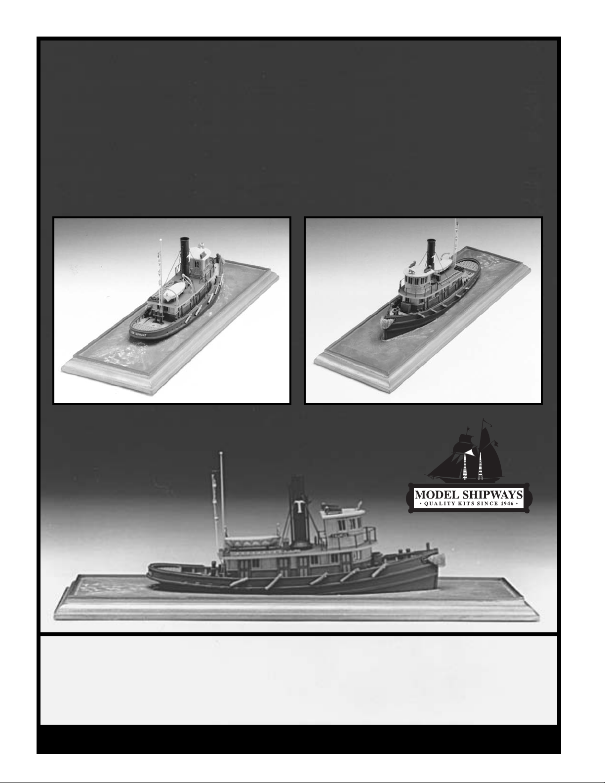
Steam Towboat
Steam Towboat
TAURUS
TAURUS
Towboats, like the TAURUS, were a
familiar sight in every American har
bor and navigable tidal flat at the turn
of the century. Graceful, yet functional, they pulled large liners and
pushed heavy barges with ease. Dur-
Model Shipways Kit No. 2021
ing the 1930's, steam engines lost
ground to Diesel propulsion, and
by the 1960's the steam units were
all but gone. A few steam tugs sur
vive today as museum relics.
Technical Characteristics:
Scale: 1/8" = 1' 0" (1:96)
Length: 9"
-
Height: 3-1/2"
Hull width: 2-1/4"
Page 2

Page 3

Instruction Manual
The Steam Towboat
Taurus
By Erik A. R. Ronnberg Jr., 1978
Instruction Manual Update By Ben Lankford, 1995
The Model Shipways kit is based on the tugs Betsy Ross of Philadelphia, 1903, and
the Sommers N. Smith of Boston,1887. Photos No. 2847 and 2156A, respectively, are in
the collection of the Steamship Historical Society, now in the library of the University
of Baltimore.
During the original development of the kit, Mr. Ronnberg was assisted by Mr. Willie
Dunne, Mr. Alan Frazer, and the librarians at the Historical Society. Their assistance is
greatly appreciated.
This new instruction manual expands on the original instructions prepared by Mr.
Ronnberg. The manual takes you through a step-by-step procedure for building a fine
ship model. Beginners and advanced modelers alike should find this a very rewarding project.
Copyright 1995
Model Shipways, Inc.
Sold and distributed by Model Expo, a division of Model Shipways, Inc.
Hollywood, FL 33020
www.modelexpo-online.com
3
Page 4

CONSTRUCTION STAGES & TABLE OF CONTENTS
Brief History Cover
Introduction/Credits Pg 3
Before You Begin Pg 5
What You'll Need to Start Construction Pg 6
How to Work With the Plans & Parts Pg 6
Painting & Staining the Model Pg 7
Stage A: Shaping the Pre-Carved Hull Pg 8
1. Shaping the Outside of the Hull Pg 8
2. Carving the Bulwarks and Deck Pg 8
Stage B: Completing the Basic Hull Pg 9
1. Installing the Stem Pg 9
2. Installing the Rubbing Strakes Pg 9
3. Planking the Deck Pg 9
4. Installing the Bulwark Stanchions and Rails Pg 9
Stage C: Mounting the Hull Pg 10
Stage D: Adding the Hull Details Pg 10
1. Stern Grating Pg 10
2. Hawse Pipe Lips Pg 10
3. Bow Fender Pg 10
4. Bitts and Bow Post Pg 10
5. Deck Plates Pg 10
6. Main Cabin Pg 10
7. Pilot House Pg 11
8. Smoke Stack, Whistle and Steam Vent Pipe Pg 11
9. Boat and Davits Pg 11
10. Mast and Towing Lanterns Pg 11
11. Ladders Pg 11
12. Stowage Chests Pg 11
13. Rail Stanchions Pg 12
14. Running Lights and Eagle Pg 12
15. Name Boards and Lettering Pg 12
16. Side Fenders Pg 12
Bibliography Pg 13
4
Page 5
BEFORE YOU BEGIN
The model is a waterline type ( no hull
below the waterline ). At 1/8" scale, it
makes a fine shelf model mounted on a
"sea" baseboard. It can also be used ef-
fectively in an HO gauge model railroad
setting. Although HO is 1/87 scale, 1/8"
( or 1/96) is close enough for the HO
layout. What you will have is slightly
smaller boat.
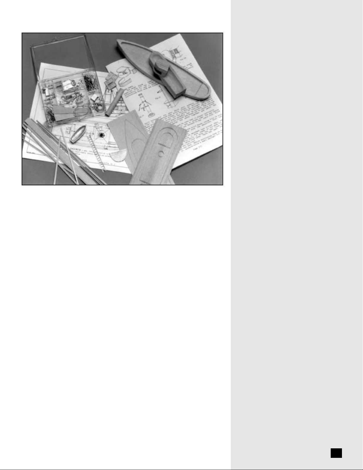
This kit contains a solid hull which has
been machined carved from select,
medium hard, fine grained basswood.
This style hull provides a quick and easy
lesson in the basic shapes and propor-
tions of hull design and helps to develop
woodworking skills. The exterior of the
TAURUS hull has been carved close to
the intended shape, so a simple sanding
is all that is required. Some carving is re-
quired for the bulwarks. Shaping and
finishing the hull to its final shape are
discussed in the instructions.
If you are a beginner, take your time. This
model is fairly simple to build but still re-
quires some time and concentration.
Make sure you complete one stage before
moving to the next. When things go
awry, consider doing it over. Completing
this model will prepare you for a more
complicated solid hull model such as the
Fishing Schooner ELSIE or the Colonial
Schooner SULTANA. Good luck!
5
Page 6

HOW TO WORK WITH
PLANS AND PARTS
Before starting model construction, exam
ine the kit and study the plan carefully. Fa
miliarizing yourself with the kit will serve
two purposes. First, it will let you determine that all parts have been supplied as
listed. And second, you'll be surprised at
just how quickly handling the parts allows
you to better understand the kit requirements. Try to visualize how every part will
look on the completed model. Also, deter
mine ahead of time what must be done
first. The instructions will help you in this
regard, but a thorough knowledge of the
plan at the outset is essential.
It is suggested that all small fittings and
hardware be sorted into labeled boxes or
compartments to avoid loss during the
building process.
1. The Plan
One Plan Sheet is provided. However,
many sketches throughout this manual
further illustrate the various stages of
construction.
The TAURUS kit is manufactured to a
scale of 1/8" = 1'0". The plan is drawn to
the exact scale that the model is to be built.
Dimensions can be lifted directly off the
plan by using a set of draftsman dividers
or by using a "tick" strip, which is simply a
piece of paper used to "pick up" the dimensions (a roll of calculator tape works
very well). Lay your paper strip over the
plan and mark the lengths of items carefully with a sharp pencil. Then use the
strip to transfer the marks to the wood or
item to be made to scale.
2. Kit Lumber
Your kit may contain limewood, a Euro
pean wood, as a substitute for the basswood. Both woods are similar in workability and grain.
3. Cast Metal Fittings
The kit is supplied with Britannia metal
castings. The Britannia metal is a great
improvement over the white metal that
was used in some older kits. Unlike
white metal and pewter, Britannia does
not contain lead, so there are no possible
corrosion problems. The fittings, however, will require final finishing before they
are suitable for installing on the model.
Before painting the cast metal fittings,
clean them up by removing all the mold
joint flash. To do this, use a No. 11 hobby
blade to cut the flash, then file or sand with
fine sandpaper. It is also suggested that
you clean the fittings thoroughly with
warm soapy water before applying primer.
Make sure they are rinsed thoroughly and
allowed to dry before painting.
-
-
WHAT YOU’LL NEED TO START CONSTRUCTION
The following tools and supplies are recommended for the construction process.
-
Modelers who have built before may
have their own favorites.
A. Knives & Saws
1. Hobby knife with No. 11 blades
2. Coping saw (or jeweler's saw
frame) and fine blades
B. Files
Set of needle files
C. CarvingTools
Small chisel and gouge for shaping
the bulwarks
D. Sharpening Stone
Necessary to keep the tools razor
sharp
E. Clamps
1. Several wooden clothespins
3. Rubber bands
F. Wire Cutters & Tin Snips
For cutting fine wire & chain; for
cutting brass sheet
G. Boring Tools
1. Set of miniature drills: #60 to #80
2. A pin vise
3. Larger bits: 1/16", 3/32", and 1/8"
H. Miscellaneous
1. Tack hammer
2. Tweezers (a few)
3. Miniature pliers
a. small round for forming rings
and eyes
b. flat nose (with serrated jaws)
4. 1/2" or 3/4" masking tape
I. Sandpaper
Fine and medium grit garnet or
aluminum oxide sandpaper
(#100 to #220 grit)
J. Finishing:
Paint brushes
a. fine point for details
b. 1/4 flat square for hull
K. Supplies:
(will be covered in detail in the
Painting & Staining section and
throughout instructions.)
1. Paints
2. Primer
3. Stains/varnish
4. White or Carpenter's (yellow)
wood glue
5. Five minute epoxy
6. Super glue
7. Model airplane type glue
Note about Glues: White or Carpenter's
yellow wood glue will suffice for most
of the model. Five-minute epoxy provides extra strength for gluing fittings.
Cyanoacrylate (Super) glue such as Jet,
can be used for quick adhesion. The best
cyanoacrylate glue for most applications
is a medium viscosity gap-filling type.
The watery-thin type is recommended
to fill a narrow crack by capillary action.
For scribed decking sheets, it is best to
use a contact cement or model airplane
type cement. White glue tends to warp
thin sheet wood and makes it difficult to
install.
6
Page 7

PAINTING & STAINING THE MODEL
It may seem strange to begin an instruction manual with directions on applying
the finishes to the model. Not so! Much
time and effort can be saved, and a more
professional result can be obtained, if
the finishing process is carried out dur
ing construction. Paint the various small
parts before they are installed on the
model.
The painting sequence must be a well
thought out procedure, otherwise you
may have difficulty as you proceed with
assembly. For example, it is easier to
paint a cabin or hatch coaming before it
is glued to the deck. Put the parts aside
until they are ready to be installed.
Proper timing in application of finishes
and the use of masking tape to define
painted edges should eliminate unsightly glue marks and splotchy stained surfaces. In the end, following these general
suggestions will be to your advantage.
-
1. Preliminaries
Before painting, rub down all external
surfaces with 220 grit dry sandpaper
and wipe off all dust thoroughly. Give
all unprimed surfaces two coats of
primer. A very light sanding is recommended after the last coat of primer, but
don't sand down to bare wood. With
clean hands, a soft brush, and a clean,
soft rag or tack rag, gently dust and
wipe off the hull.
Choosing paint:
a flat finish paint. Glossy finishes are not
desirable. A satin finish will give the
most satisfactory results, but the undercoat (primer) paint should be dead flat.
Floquil marine color paints are ideal. If
you object to solvent based paints, Floquil's Polly-S is an excellent water-based
acrylic and brushes and covers well.
Clear finishes are available for both
types of paint so you can get the gloss or
flatness you desire.
Masking off surfaces
tricky to mask off the surfaces you don't
want to paint. Some brands of masking
tape are absolutely no good because
they allow paint to bleed under them, so
be selective. The Scotch Brand remov
able magic tape is a good tape. The adhesive is low-tack, the same adhesive
used for their Post-It note paper. A
graphic design tape, such as the Chart
Pak brand, is also good but the adhesive
grips rather securily. If you use it, make
sure your paint is thoroughly dry. It is
available in widths as fine as 1/32" and
1/64". Black plastic electrician's tape is
also acceptable.
A secret to good masking is to lightly
paint a clear finish along the tape first.
For hand brushing, use
: It can be very
-
This seals the edges so the color paints
won't run under the tape. Floquil flat
finish or crystal cote will do the trick.
Spray Painting
work best with fast drying lacquers. The
Floquil paints spray very well when
thinned about 25%, used in an airbrush
such as the Testors and Badger units.
You will also find many brands of paint
available in aerosol cans which give
good results. Test them on a wood block
as previously described before using
them on the model. The aerosol cans put
out much more paint than an airbrush,
so you must spray lightly and fast. Don't
let the paint build too heavily, or you
will have a mess of runs.
Brush painting
bristle brushes is probably best for the
beginner. And many highly skilled
modelmakers prefer the brushed on
technique because a brushed surface,
with its fine imperfections, imparts a
more life like appearance to the model.
Choosing Brushes
soft and of the highest quality. Artist
grade sable or synthetics are the best.
They should be a littler wider for painting the surface. A brush that's too narrow will cause excessive streaking of the
finish.
Brushing Technique
paint or stain with a brush, lay down one
thin coat in a single stroke, then move the
brush over to coat the adjacent areas with
single strokes. Never make repeat strokes
over fresh paint or you will tear up the
surface of the first brush stroke. Wait
until the paint has dried to a hard finish
before applying a second coat.
: Spraying techniques
: Painting with fine, soft
: Brushes must be very
: When applying
2. TAURUS Color Scheme
Color schemes on tugs varied considerably. Here are some of the more common ones.
Hull: Black, or dull or weathered black;
Boston tugs often were white.
Cap rails: Always black.
Deck: Well maintained but not fancy;
use a greyish-umber, or teak stain.
Cabin and pilot house sides: Red was a
favorite; Boston owned tugs may have a
cherry or mahogany stained cabin to
contrast with white hull. The box photo
shows a cabin with mahogany for half
the cabin and natural or oak finish for
the upper half.
Cabin and pilot house top: Canvas covered, paint light grey or buff.
Doors and windows: Bright varnished
oak.
Bulwarks inboard: Buff, grey or red
oxide.
Stern grating: Dark brown holes and
lighter brown top surface.
Quarter bitts: Black or red oxide
Stack, rail stanchions, and deck plates:
Black
Running lights: Brown box; port light is
red, starboard light is green.
Eagle on pilot house: Gold
Boat: White with tan or light grey cover.
7
Page 8

STAGE A
FIG. 1 – Hull Sections at the Bow, Amidships and Stern
SHAPING THE
PRE-CARVED HULL
1. Shaping the Outside
of the Hull
The outside of the pre-carved hull can
be shaped very easily with a sanding
block. About all you need do is even up
both sides with a sanding block. The
stern has vertical sides down to a sharp
edge, then tapers back to the waterline.
Sand the bottom slope to obtain the
sharp edge. Figure 1 illustrates a section
at the bow, amidships, and at the stern.
Using the sanding block, smooth out
the top of the bulwarks so you have a
smooth curve (hull profile) and maintain a sharp edge along the bulwark.
Next, decide on how you want the stem
to look. Figure 2 shows three variations
that you can use. Using a sanding block,
shape the bow to accept a stem piece.
The "catboat" stem (Figure 2c) was very
popular among tugs designed with a lot
of barge pushing in mind.
2. Carving the Bulwarks
and Deck
The machine-carved hull has bulwarks
approximately 1/8" thick. They are
thicker than required so they won't
break while inside the kit box. The inboard sides of the bulwarks need to be
cut down to a uniform thickness of
about 1/32". However, this will be difficult and leave the bulwarks very weak.
Although a little thick, you can cut
them down to only 1/16". If you want
to simplify the bulwarks and omit the
timberheads, the bulwarks can be thicker. If timberheads will be added, strive
for a thinner bulwark. The cap rail must
cover the bulwark plank plus the top of
each timberhead. If both are too wide
the cap rail will be wider than scale and
look very bulky. Figure 3 shows a
method for cutting the bulwark thickness down. Use a gouge to cut to the
depth, then smooth the surface with a
flat chisel. A small sanding block will
complete the task.
As you proceed around the stern, use
the grating casting provided in the kit
and test fit it as you go so the grating
will fit snugly against the bulwarks.
The deck will be covered with the
scored deck sheet included in the kit,
unless you desire to lay individual
planks as an option. In any case, you
must first take a chisel and square up
the corners at the bow and at the deck
Keep
bottom
Sharp
edge
Softer
edge
edge sharp
FIG. 2 – Variations of the Stem
ABC
FIG. 3 – Cutting the Bulwark Thickness
Mark width
Gouge
FIG. 4 – Carving the Deck
Square
corners at
stern grate
FIG. 5 – Installing the Rubbing Strakes
Cut from
sheet
Straight
strips
Smooth
with
chisel
Catboat stem
1/32" to
1/16"
Cut out
at bow
Sand to shape
8
Page 9

grating step aft. Square these areas and
sand the deck smooth (see Figure 4).
At this stage, the hull is fully shaped. Go
over the entire hull with sandpaper,
using #220 grit for the final smoothing.
Be careful not to round the upper edges
of the rail, the hull angle aft, and the bot
tom (waterline). These should be sharp
corners.
Before proceeding to the next stage, it
would be a good idea to drill a couple of
pilot holes in the bottom of the hull if
you intend to have the boat mounted on
a baseboard.
STAGE B
COMPLETING THE BASIC HULL
1. Installing the Stem
Precut the stem and glue it to the bow.
The stem should have a very slight
taper to it. Make sure the grain of the
wood is in line with the piece.
FIG. 6 – Planking the Deck
Decking
-
Waterway strip
Scupper slot
FIG. 7 – Installing the Rails
Rough
File to shape
2. Installing the
Rubbing Strakes
Using a 1/16" strip, pre-shape the rubbing strakes. The straight sticks can be applied from the stem back to about the
front of the deck grating (the lower strake
feathers out at the waterline). Mark the
location of the rubbing strakes on the hull
with a pencil. For the stern you can cut
the strakes out of a 1/6" sheet. Make it a
little wider than necessary. After it is installed, sand it down to match the other
section of strake (see Figure 5).
As an option for the stern, you could
steam-bend or ammonia soak a strip to
soften it for bending around the stern.
Also, you may want to try laminating
several thin strips to obtain the shape.
3. Planking the Deck
For this model, you can lay individual
planks as an option, or use the scored
decking included in the kit. For the
scored sheets, first make a paper template to fit snugly against the bulwarks.
Place the template on the scored sheet
and cut the sheet with a hobby knife.
Glue the deck sheets down with model
airplane type cement or contact cement.
White or Carpenters wood glue tends to
warp the wood. Make sure you have
the scored lines lined up with the centerline of the boat.
The waterway along the bulwarks were
generally planks flush with the deck.
For the model they can be faked by
adding a 1/8" wide paper strip, glued
FIG. 8 – Installing the Rub Rail and Spray Rail
Spray rail
Rubrail
on top of the scored decking (see Figure
6). If you prefer a wood waterway, you
can trim 1/8" off the edge of the scored
decking and glue on a waterway piece.
After the waterway is in place, cut the
scupper slots through the bulwarks (also
shown in Figure 6). Use a small drill and
needle file to shape up the slots. The
plan also shows a larger hole aft which is
a freeing port. This is optional. The vertical lines are bars, added in the hole to
prevent loosing a tow line through them.
4. Installing the Bulwark
Stanchions and Rails
If you are going to add them, the bulwark stanchions should be about 1/32"
square. Starting at the bow, space them
about 1/4" apart. At the scuppers, the
stanchions should be at the end of the
slot, not in way of the slot. Cut each bulwark stanchion to length and glue in
place. Cutting and mounting the stan
chions is tedious work, so exercise great
care in the installation.
-
Glue the main rail atop the bulwark and
stanchions, making sure it extends
slightly beyond the bulwark outboard
and stanchions inboard. The rail portion
around the stern can be made the same
way as discussed for the rubbing strakes
(see Figure 7 ). Finally, add the rub rail
at the stern and spray rail forward (see
Figure 8 ).
9
Page 10

FIG. 9 – Installing the Bitts
and Bow Post
FIG. 10 – Main Cabin Panel Construction
Mark with pencil
Belt rail
Coaming
Vertical panel
Horizontal panel
Window Door
STAGE C
MOUNTING THE HULL
If you are going to mount your model on
a baseboard, as opposed to using it in a
model railroad layout, now would be a
good time to do it to prevent details from
becoming damaged during handling.
The kit includes a wooden baseboard.
For a boat sitting in the water you can
add some strips of wood along the edge
of the baseboard, projecting 1/8" or so
above. The model can be mounted with
screws into the pilot holes you drilled in
the hull. For water, you can use paint, or
paint the baseboard, then pour casting
resin or acrylic gel over the paint. This
makes a realistic looking sea bed. The
photo on the kit box shows how it looks.
STAGE D
ADDING THE HULL DETAILS
Before beginning with the details, outline all topside items on the deck by
marking their locations with a pencil.
Take all measurements from the plans
using tick strips.
1. Stern Grating
The stern grating is a Britannia casting.
Clean it up, prime it and paint it before
installation. If you carved the bulwarks
using the casting as a pattern, it should
fit nicely.
2. Hawse Pipe Lips
Drill holes in the bow and glue the Bri
tannia hawse pipe lips over the hole.
Shape the hole with a file so it blends in
with the hawse pipe lips.
3. Bow Fender
The bow fender is provided as a Britannia casting but should be enhanced by
adding "rope whiskers"; for the model
glue on some short pieces of thread so it
appears nice and fuzzy like the real
fender.
-
FIG. 11 – Adding the Steering Linkage
Roller
4. Bitts and Bow Post
The bitts and bow castings could be
added later, but it is probably a good
idea to get these in place before adding
the cabin. Again, these are best painted
before being installed (see Figure 9).
5. Deck Plates
The four deck plates on the deck, the
round circles adjacent to the stack, are
for passing coal to the bunkers located
on both sides of the boiler. These plates
are iron set flush with the deck planking. For the model, simple paper punchings from a 1/4" paper punch will serve
the purpose, or you can cut out holes in
the scored decking and insert a piece of
wood cut to the correct diameter.
6. Main Cabin
The cabin is provided machine-carved.
However, check the shape. The cabin
should be about 1/16" smaller all
around than the plan. To the sides of the
cabin, you will add covering sheets and
door and window castings. When
added, the cabin should be the correct
dimension.
With a pencil, lay out lines to locate all
the doors, windows, and a horizontal
line for the side panelling. The panelling
is to represent tongue and groove
sheathing on the real craft. Cut the panelling from the scored sheet provided in
the kit. Arrange the panelling as shown
on the plans and in Figure 10. Notice the
panels are horizontal below the scribed
line, and vertical above. As an option,
Chain
Eye
Rod
you could glue individual strips of
wood to form each panel plank.
Glue each door and window casting in
place. Since the windows are open, paint
the cabin behind the windows black, or
light blue to simulate the glass. Do this
before installing the windows. You
could also be daring and insert some
plastic sheet in the window openings to
create some reflection like real glass.
Your choice.
Along the separation of the vertical and
horizontal panels, and at the deck, you
need to add a belt rail and coaming.
Thin, stiff paper like bristol board is
ideal. Make the rail about 1/32" wide,
and the coaming at the deck 1/16" wide.
Next, center the cabin and glue it to the
deck. At this point, it would be a good
idea to add the steering linkage which
connects the steering gear in the pilot
house with the steering quadrant which is
under the stern grating ( see Figure 11).
The linkage has a short chain on each end,
with a connecting rod going through deck
eyebolts. Although you can't see it, the
forward chain is connected to a rope or
light chain which passes over rollers up to
the pilot house steering wheel drum.
Make another pattern for the cabin top
and cut the top from sheet wood. Do not
use scored sheet. The top is canvas cov
ered so the plank seams do not show.
For the edge of the cabin top, you can
leave it as is, or glue a thin strip of paper
or wood around the edge (see Figure
12). Glue the top in place, being careful
to align it evenly. When it is set, mark
the locations of the topside items in pen
-
-
10
Page 11

FIG. 12 – Adding the Cabin Top
FIG. 13 – Beveling the Pilot House
FIG. 14 – Completing Assembly of the Pilot House
cil, then drill holes for the rail stanchions
and the towing light mast.
FIG. 15 – Vent Pipe FIG. 16 – Boat Covering
Shape to fit window
Mark
Fit
Window
Step
7. Pilot House
The pilot house is also a machine-carved
structure. It is cut out in way of the windows so you can look through the opening. You may need to trim the opening
so the windows fit properly. Paint the
interior black so you can't see the wood.
For the windows, leave open or add
clear plastic sheet in each pane.The rest
of the pilot house is done exactly like the
main cabin. Check for fit on the main
cabin, and sand the bottom if necessary
to fit. Finally, glue the completed pilot
house on top of the main cabin, and
make a small step at the door (see Fig
ures 13 and 14 ).
-
8. Smoke Stack, Whistle, and
Steam Vent Pipe
Smoke stack parts include a wooden
stack dowel, Britannia casting base and
"T" emblems, brass rings and chain guys,
and Britannia whistle and vent pipe (see
Figure 15 ).
You may need to bore out the base a little
to receive the stack dowel. Fit the brass
rings over the dowel as shown. Drill a
hole for the "T" emblems, and holes for
the guy chain eyes at the mid ring. Insert
a U-shaped staple of brass in the holes for
attaching the chain. Install the whistle and
vent pipe in the holes in the stack base.
Prime and paint the entire unit.
Install the stack, making sure it is verti
cal and has the proper rake aft (see the
-
plan). File the bottom of the base if necessary. Attach the chains to the cabin top
with similar staples.
9. Boat and Davits
The boats can be positioned as shown on
the plan or moved closer to the cabin
edge.The boat can be either on the port
or starboard side. If at the cabin edge,
you could scratch build a small skylight
for the engine room. The kit box photo
shows an old wooden ladder atop the
cabin. Be inventive!
Make a cover for the boat out of fine
cloth or paper (see Figure 16). The boat
can be hung from the davits using
thread or a piece of brass wire.
10. Mast and Towing Lanterns
Fit the mast through a hole in the cabin
top, but first install a hanger from brass
wire into the mast for the lantern halliard (see Figure 17). The halliard can be
thread or brass wire. Notice on the kit
box photo, a small block was added at
Cover
FIG. 17 – Lantern Halliard
the top for the halliard. It gives the
model that extra touch.
11. Ladders
Add the port and starboard ladder going
up to the cabin top. The top should be
curved as a hand rail.
12. Stowage Chests
Install the forward stowage chest for
ward of the main cabin, and the lifebelt
-
11
Page 12

stowage chest aft of the smoke stack.
Glue with epoxy to set them securely.
13. Rail Stanchions
The rail stanchions fit into the holes you
drilled on the cabin top. After gluing, feed
the brass railing wire through the stanchions and touch with a little super glue.
14. Running Lights and Eagle
Make sure you have the lights painted
the correct color. Remember Port (like
wine) is red. The eagle is installed on the
pilot house front.
15. Name Boards and Lettering
You could name this boat anything you
like. TAURUS is Model Shipways name
for a typical tug. The name can be hand
painted, or you can use dry transfer lettering from an art store.
16. Side Fenders
On the real boats, fenders were made
from old railroad ties or sawed-off logs.
For the model, cut some twigs off your
favorite bush and stain them to look
weathered. These make nice realistic
fenders.Glue to the bulwarks and use
thread for the securing lines.
After all is done, look over your prize
and touch up paint if necessary. Make a
final check with the plan to see that you
have included all parts. Add the water
to your baseboard if you have not already done so.
Congratulations!
Your model is now complete. Don't
hesitate to call Model Expo when
you are ready to begin your next
modeling endeavor.
12
Page 13

BIBLIOGRAPHY
1. Brady, E. M., Tugs, Towboats, and Towing. Describes operation of modern
tugs with many glances backward at steam units. Good stuff on towing gear
and techniques.
2. Lang, Steven,
graphic overview of tugs through time and in most regions of America.
3. Campbell, G. F.,
Describes modelwork of a general nature, drawing examples from many
types of sailing ships. Contains some good hints on crafts techniques. Excellent for the beginner.
On the Hawser. A tugboat album offering a varied photo
The Neophyte Shipmodeler's Jackstay, Model Shipways, 1962.
-
13
Page 14

TAURUS INSTRUCTIONS
FOR LASER-CUT CABIN AND
PILOT HOUSE
The TAURUS kit has been modified to include
laser-cut lifts and cabin tops for the main cabin
and pilot house. These laser-cut parts replace
the solid wood machine carved structures supplied in earlier kits.
These instructions apply to assembly of the
laser-cut parts. Once assembled, refer back to
the Instruction manual for addition of siding,
windows, and doors.
MAIN CABIN
Cabin lifts
1/8” thick
8 required
Cabin top
1/32” thick
1 required
Step. 1
- Glue the 1/8" cabin lifts together.
Step. 2 - Shape the top and bottom of the
cabin lifts to follow the deck sheer line. The
front also needs to be sloped back a bit. This
can be done with a sanding block. See Figure
1.
Step. 3 - Glue on the 1/32" cabin top. The
cabin top is slightly smaller than the plan to
allow for adding the edge molding (see Instruction Manual).
Step. 4 - Return to the Instruction Manual for
instructions on installing the windows, doors,
and siding.
PILOT HOUSE
Step. 1 - Glue up the three 1/8" lifts with curved
front. On top of these glue on two of the 1/32"
lifts supplied in the kit. Glue the three 1/8" rectangular lifts on the aft side. Next, add two more
1/32" lifts. You now have a pilot house with a
cut-out in way of the windows, so you can see
through.
Step. 2 - Glue on the 1/32" thick pilot house
top. See Figure 2.
1/8” thick
3 required
Pilot house
lifts 1/8” thick
3 required
Pilot house lifts at
windows 1/32”
thick 4 required
1/8”
1/8”
Pilot house top
1/32” thick
1 required
1/32” top
2@1/32”
2@1/32”
FIGURE 2
Step. 3 - Return to the Instruction Manual for
instructions on installing the windows, doors,
and siding.
14
FIGURE 1
Shape profile
Page 15

MODELER'S LOG
Date Time Notes
15
Page 16

Other Fine Kits from
Model Shipways
SULTANA
Model Shipways Kit No. MS2016
WILLIE L. BENNETT
Model Shipways Kit No. MS2032
OUR GUARANTEE
If less than delighted, return your purchase within 30 days in original condition.
BLUENOSE
Model Shipways Kit No. MS2130
CHARLES MORGAN
Model Shipways Kit No. MS2140
RATTLESNAKE
Model Shipways Kit No. MS2028
BENJAMIN LATHAM
Model Shipways Kit No. MS2109
PHANTOM
Model Shipways Kit No. MS2027
NIAGARA
Model Shipways Kit No. MS2240
SAVE TIME & MONEY ...ORDER DIRECTLY FROM OUR WEBSITE!
EMMA C. BERRY
Model Shipways Kit No. MS2150
FLYING FISH
Model Shipways Kit No. MS2018
BEDFORD WHALEBOAT
Model Shipways Kit No. MS2645
PRINCE DE NEUFCHATEL
Model Shipways Kit No. MS2110
MODEL SHIPWAYS, INC.
Sold & Distributed by Model Expo, a division of Model Shipways, Inc.
race, Hollywood, FL 33020
3850 N. 29th T
er
Toll-Free 800-222-3876 Monday - Friday 9-6 ET • Fax 800-742-7171
http://www.modelexpo-online.com
USS CONSTITUTION
Model Shipways Kit No. MS2040
PRIDE OF BALTIMORE II
Model Shipways Kit No. MS2120
 Loading...