

Modellbau Lindinger SebArt Serues, PittS 12 Python 50E ARF Assembly Manual

SebArt professional line
Modellbau Lindinger GmbH
Modellbau Lindinger GmbH Alte-Post-Str. 14 A-4591 Molln e-Mail: office@lindinger.at www.lindinger.at
PittS 12 Python 50E ARF
ASSEMBLY MANUAL
The new PittS 12 Python 50E
ARF was designed by Italy
aerobatic pilot, Sebastiano Silvestri.
This professional ARF kit is the result of Sebastiano’s long
research in 3D performance and precision. This combined with an
extremely lightweight structure, the all wood airframe and the big
control surfaces give the PittS 12 Python 50E an impressive
thrust-to-weight ratio and crisp control authority at any airspeed
and flight condition.
The PittS 12 Python 50E can do it all… precision aerobatics
manouvres… easy harriers, torque rolls, blenders, waterfalls and
all this for a biplane of this class is unbelievable!
.....the only aerobatic limit is your fantasy!
Specifications:
Wing Span:..……….…….........................135 cm Recommended power set up:
Length:…….............………………….... 145 cm Motor:....................... Hacker A50-16S
Wing Area:……...................................... 61 dm2 ESC:…………Master basic 70 S-BEC
Weight:….....................2.300 g. RTF less battery Battery: ……….Flight Power 4270-6S
Radio: 6-Channel with 4 mini + 2 standard servo Propeller: ..………..……. APC 17x8E

Table of contents
Modellbau Lindinger GmbH
Modellbau Lindinger GmbH Alte-Post-Str. 14 A-4591 Molln e-Mail: office@lindinger.at www.lindinger.at
Table of contents...............................................................................................................……….. 2
Required radio, motor and battery.............................................................................................…. 3
Additional required items, tools and adhesives.............................................................................. 3
Warning.......................................................................................................................................... 3
Before starting assembly ...........................................................................................................… 4
Using the manual........................................................................................................................... 4
Warranty information…................................................................................................................. 4
Section 1 – top & bottom wing’s ailerons installation.................................................................... 5
Section 2 – aileron servo & control horn installation…............................................................…. 6
Section 3 – rudder & tail wheel installation .................................................................................. 9
Section 4 – elevator installation……………………...................................................................... 12
Section 5 – elevator servo & control horn installation ………...................................................... 14
Section 6 – rudder servo & control horn installation…...............…........................................…. 16
Section 7 – wing’s pylon & top wing installation……………............….......................................17
Section 8 – landing gear & wheel installation................................................................................ 22
Section 9 – electric motor installation…………….......……......................................................... 25
Section 10 –.transparent canopy installation.........................................................................……. 27
Section 11 – final radio installation ……………........................................................................... 28
Section 12 – decal set application………………........................................................................... 31
Control throws…………………….......................................................................................……. 32
Mixing............................................................................................................................................. 32
Rates & expos.............................................................................................................................… 32
Recommended CG......................................................................................................................… 32
Pre-flight…................................................................................................................................….. 33
Range test your radio..................................................................................................................…. 33
2

Required radio, motor and battery
Modellbau Lindinger GmbH
Modellbau Lindinger GmbH Alte-Post-Str. 14 A-4591 Molln e-Mail: office@lindinger.at www.lindinger.at
Radio equipment:
• 6-channel radio system
• 4 digital mini servo for ailerons, recommended JR PROPO DS385 or DS381
• 2 digital standard servos, recommended JR PROPO DS 9401
• 2 servo extension 300mm, for rudder and elevator servos
• 4 servo extension 100mm, for aileron servos
• 2 “Y” leads for aileron servos
Recommended electric motor for best performance:
• Hacker A50-16S + Master Basic 70 S-BEC + APC 17x8E
Recommended Li-Po battery pack for best performance:
• FlightPower 3700mAh 6S.….for unlimited 3D
• FlightPower 4250mAh 6S…..for 3D, duration and precision
Additional required item, tools and adhesives
Tools:
• Drill
• Drill bits: 1,5mm; 2mm; 2,5mm; 3mm
• Phillips screwdriver large and small
• Hobby knife
• Sand paper
• Soldering iron
Adhesives:
• 5-minute epoxy
• thin CA
• medium CA
Warning
This RC aircraft is not a toy!
If misused, it can cause serious bodily harm and damage to property.
Fly only in open areas, preferably in official flying sites, following all instructions included with
your radio and motor.
This plane is a compromise between Aerobatics and 3D flying, and not a pylon racer.
It is built with a very light structure and for this reason we hardly recommend:
→ Do NOT fly your airplane at high speeds, because this may cause structural
failures or flutter due to the extremely large control surfaces.
3

Before starting assembly
Modellbau Lindinger GmbH
Modellbau Lindinger GmbH Alte-Post-Str. 14 A-4591 Molln e-Mail: office@lindinger.at www.lindinger.at
Before starting the assembly of your PittS 12 Python 50E, remove each part from its bag and
protection for a prior inspection. Closely inspect the fuselage, wing panels, rudder, and stabilizer for
damage. If you find any damage or missing parts, contact the place of purchase.
If you find any wrinkles in the covering, use a heat gun or covering iron to remove them. Use
caution while working around areas where the covering material overlap to prevent separating the
covers.
Using the manual
This manual is divided into sections to help make assembly easier to understand and to provide
breaks between each major section.
In addition, check boxes () have been placed next to each step to keep track of each step
completed. Steps with two boxes indicate that the step will require repeating, such as for a right or
left wing panel, two servos, etc.
Remember to take your time and follow the directions.
Warranty information
SebArt garantees this kit to be free from defects in both material and workmanship at the date of
purchase.
This warranty does not cover any parts damage by use or modification, and in no case shall
SebArt’s liability exceed the original cost of the purchased kit.
Further, SebArt reserve the right to change or modify this warranty without notice.
In that SebArt has no control over the final assembly or material used for the final assembly, no
liability shall be assumed or accepted for any damage of the final user-assembled product. By the
act of using the product, the user accepts all resulting liability.
If the buyer is not prepared to accept the liability associated with the use of this product, the buyer
is advised to return this kit immediately in new and unused condition to the place of purchase.
SebArt di Sebastiano Silvestri
Via Trento 69/3
38017 Mezzolombardo (TN) – Italy
4
Section1 – top & bottom wing’s ailerons installation
Modellbau Lindinger GmbH
Modellbau Lindinger GmbH Alte-Post-Str. 14 A-4591 Molln e-Mail: office@lindinger.at www.lindinger.at
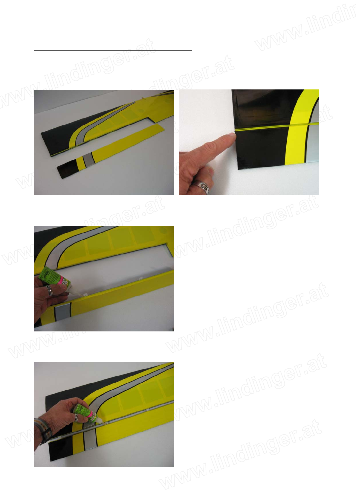
step 1
Trial fit the four aileron hinges, included in the hardware pack, in their place and verify the correct
position and alignment of the aileron with the wing panel.
step 2
Carefully glue, with some drops of thin CA, each of the four hinges in the aileron.
step 3
Locate the aileron and carefully glue, with some drops of thin CA, the hinges into the wing panel.
5
step 4
Modellbau Lindinger GmbH
Modellbau Lindinger GmbH Alte-Post-Str. 14 A-4591 Molln e-Mail: office@lindinger.at www.lindinger.at
Work the aileron up and down some times to work the hinges and check for proper movement.
step 5
Repeat steps 1 through 4 for the remaining ailerons.
Section 2 – aileron servo & control horn installation
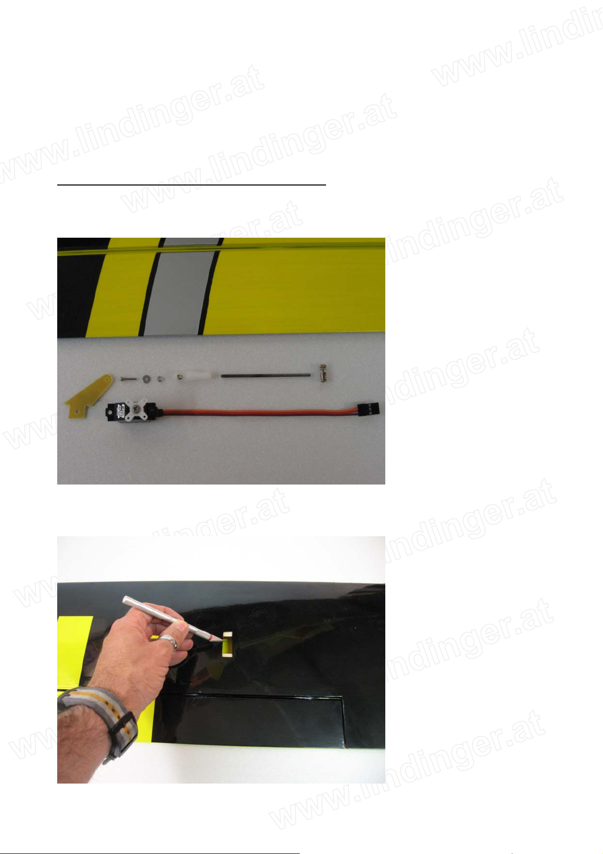
step 1
Locate the following items included in the hardware pack and the servo.
step 2
With the hobby knife open the servo bay and the control horn location.
6

step 3
Modellbau Lindinger GmbH
Modellbau Lindinger GmbH Alte-Post-Str. 14 A-4591 Molln e-Mail: office@lindinger.at www.lindinger.at
With the hobby knife open the servo lead exits in the bottom & top wing.
step 4
Carefully take out from the wing panels the nylon cable, factory located.
step 5
Install the servo hardware (gommets and eyelets), put the servo into the wing panel and bring out
the servo lead, as per pictures.
7
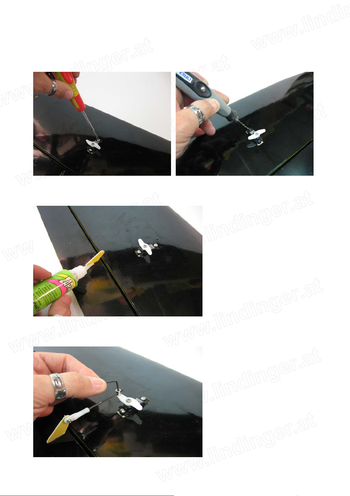
step 6
Modellbau Lindinger GmbH
Modellbau Lindinger GmbH Alte-Post-Str. 14 A-4591 Molln e-Mail: office@lindinger.at www.lindinger.at
Drill the location for the self-tapping screw using a 1.5mm drill bit and install the servo into the
wing panel as per the picture.
step 7
Glue the fibreglass horn with medium CA into the aileron.
step 8
Install the control horn as per picture.
8
step 9
Modellbau Lindinger GmbH
Modellbau Lindinger GmbH Alte-Post-Str. 14 A-4591 Molln e-Mail: office@lindinger.at www.lindinger.at
Repeat steps 1 through 2 and 4 through 8 for the remaining ailerons.
Section 3 – rudder installation & tail wheel installation
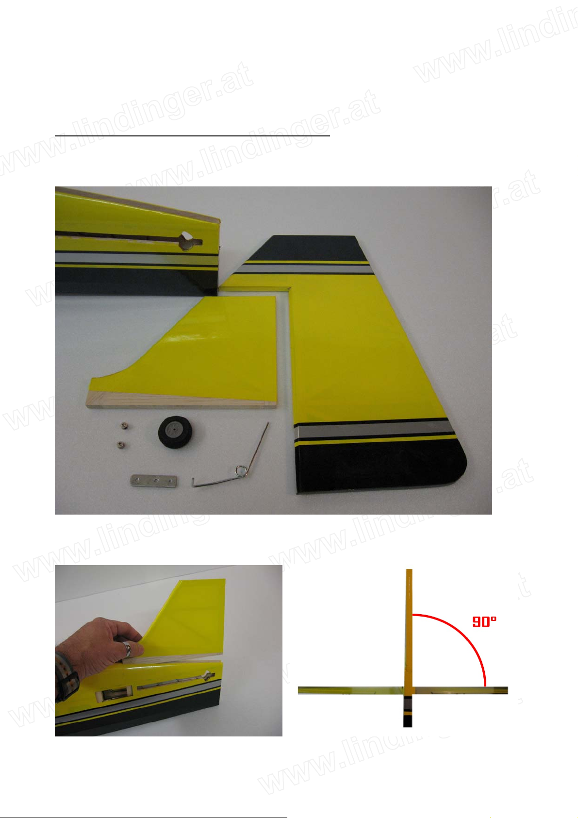
step 1
Locate the following items.
step 2
Locate the rudder in his place and check the alignment with the fuselage.
9
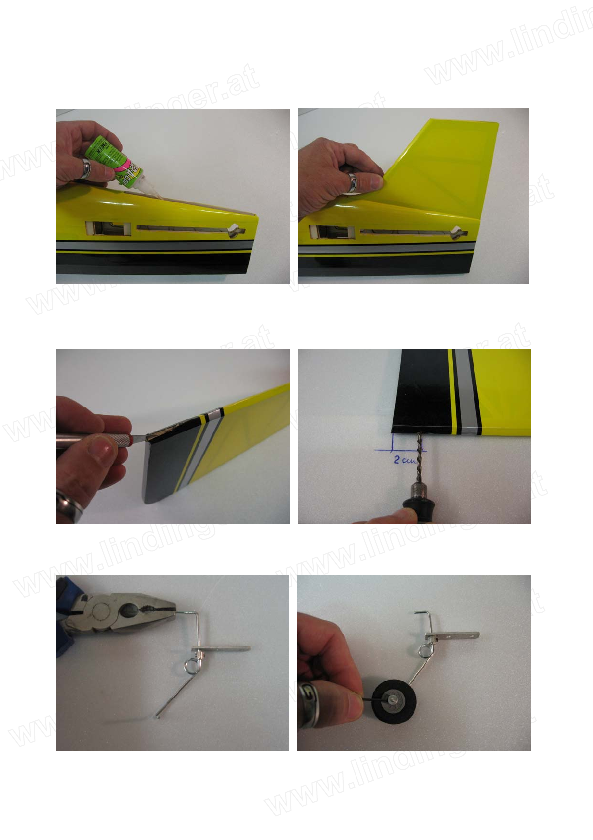
step 3
Modellbau Lindinger GmbH
Modellbau Lindinger GmbH Alte-Post-Str. 14 A-4591 Molln e-Mail: office@lindinger.at www.lindinger.at
Glue the rudder with some drops of medium CA, as per pictures.
step 4
With the hobby knife cut a groove of 20mm length into the rudder. Drill in the rudder, 20mm from
the bottom, the location for the tail wheel using a 2mm drill bit.
step 5
Assemble the tail wheel, as per follow.
10
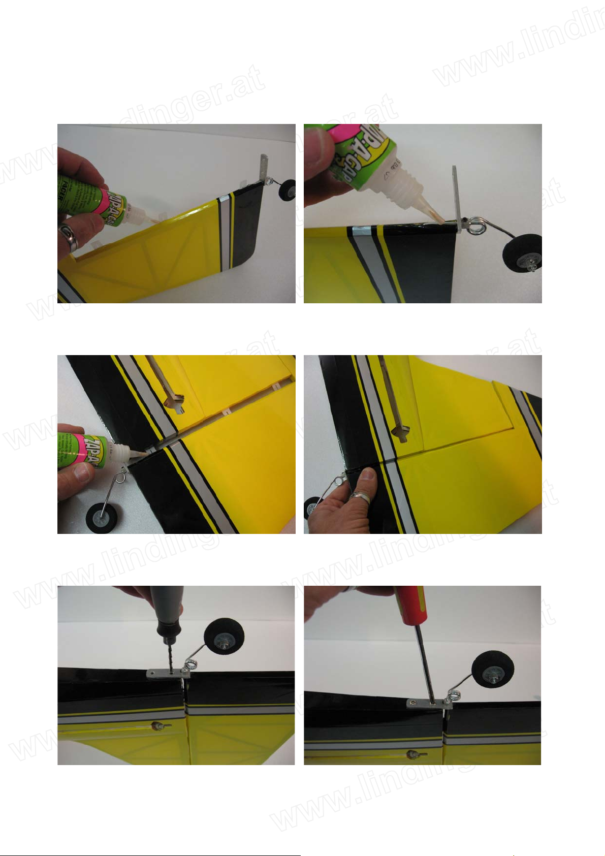
step 6
Modellbau Lindinger GmbH
Modellbau Lindinger GmbH Alte-Post-Str. 14 A-4591 Molln e-Mail: office@lindinger.at www.lindinger.at
Insert the three hinges in their appropriate slots of the rudder, and glue them with some drops of
thin CA.
step 7
Carefully locate the rudder and glue the hinges with some drops of thin CA.
step 8
Drill the screw locations for the tail wheel using a 1,5mm drill bit, and install it as per picture.
11
 Loading...