


!
IMPORTANT!
NOT A TOY!
Radio controlled model!
This high performance model
must be assembled and operated
according to the instructions.
May cause serious injury to persons or
property if not used responsibly.
Unsuitable for children under 14 years.
http://www.modelengines.com.au
Specifications:
Wingspan: 835mm
Overall Length: 930mm
Includes:
Four Channel FM Radio (installed)
Three Micro Servos (installed)
Brushless Out Runner Motor (installed)
Electronic Speed Controller (installed)
Lithium Polymer Flight Battery
Dedicated Lithium Polymer, Balance Type, Battery Charger
AC Power Adapter
Spare Propeller
Instruction Manual
Sea Vixen
Items Required:
Basic tools - Philips Head screwdriver
8 x ‘AA’ size batteries for transmitter
GUARANTEE/WARRANTY
Model Engines (Aust.) Pty. Ltd. Guarantee this product to be free from manufacturing and assembly defects for a period of
30 days from the time of purchase. This does not affect your statuary rights. This warranty is not valid for any damage or
subsequent damage arising as a result of a crash, misuse, modification or for damage or consequential da m age arising as
a result of failure to observe the procedures outlined in this manual. Operation of this model is carried out entirely at the risk
of the operator. Please note that, whilst every effort is made to ensure the accuracy of instructions and material included
with this product, mistakes can occur and neither Model Engines (Aust.) Pty. Ltd nor it’s distributors will be held liable for
any loss or damage arising from the use of this model or for any loss or damage arising from omissions or inaccuracies in
the associated instructions or materials included with this product.
We reserve the right to modify the design of this product, contents and manuals without prior notification.
© 2007 Model Engines (Aust.) Pty. Ltd., Noble Park, Victoria 3174, Australia. www.modelengines.com.au
All rights reserved. E&OE
!
Warnings!
• Radio Control Models are not toys and serious injury to persons or damage
to property can result if not used in a responsible manner
• It is not recommended for children under 14 years and should only be flown
by experienced radio control pilots
• It is recommended that this model only be flown at dedicated radio control
flying sites
• Read all instructions carefully prior to assembling and before flying this
model. Seek advice should any information be unclear. You assume all risk
and responsibility when using this model
In the UK, please observe the principles of safety as outlined by the governing
body for model flying, the British Model Flying Association (BMFA).
www.bmfa.org
In Australia, please observe the guidelines for the safe operation of radio control
models as outlined by the Model Aircraft Association of Australia (MAAA).
www.maaa.asn.au
1.
2.
3.
4.
5.
6.
7.
8.
9.
10.
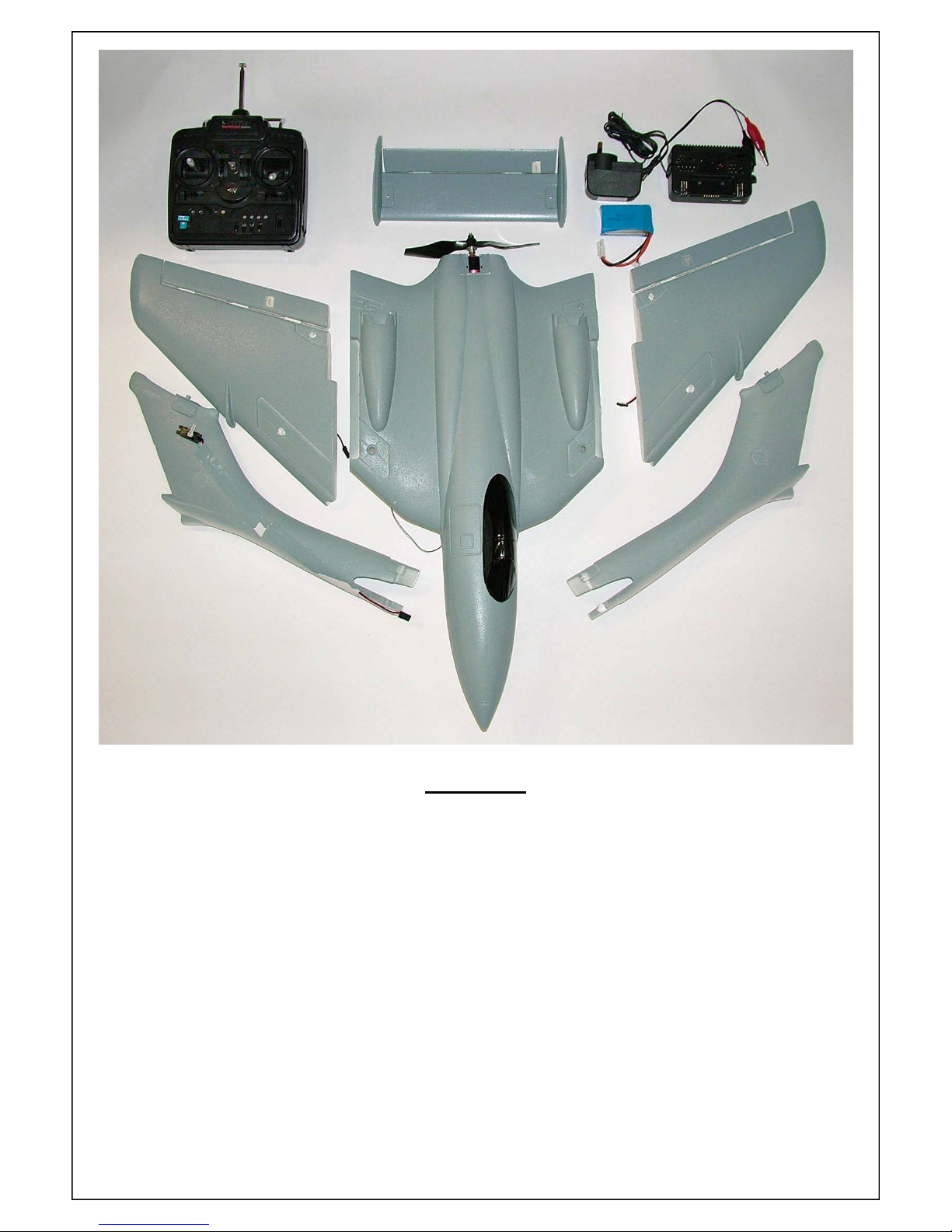
Contents
1. Four channel FM transmitter
2. Tail plane assembly
3. 240V AC power adapter
4. Lithium Polymer battery charger
5. Lithium Polymer flight battery
6. Right hand wing panel
7. Fuselage assembly
8. Left hand wing panel
9. Left hand tail boom
10. Right hand tail boom
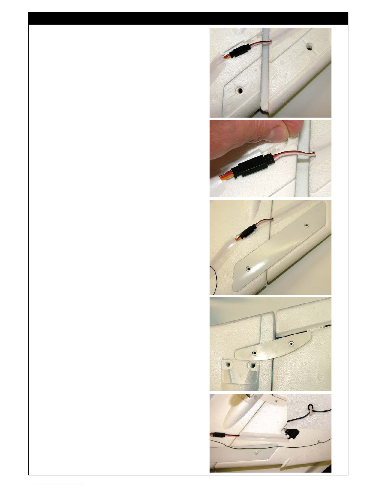
Wing Assembly
1.
Turn the fuselage assembly upside down and
line up the wing panels.
Connect the servo lead to the pre-installed
servo extension lead in the fuselage.
2.
Peel the backing off the double tape to secure
the servo lead once the wings are joined.
3.
Lay the white front and rear wing joiners in
position as shown.
4.
With the wings joined, secure the receiver
antenna as shown to keep the antenna clear of
the propeller.

Fitting the Tail Booms
5.
Lay the grey upper wing joiners in position and
secure with the screws provided.
Please note that the metal screws are used for
the rear joiners and nylon screws for the front.
6.
Push the servo connector and lead into place.
7.
Slide the tail booms into place. Note that the tail
boom with the elevator servo fitted, must be
installed with the servo on the inside of the
boom as shown.
8.
As was the case with the aileron servos, the
backing of the double sided tape to secure the
elevator servo lead, should now be removed.
9.
The tail booms are held in place by an upper
and lower plastic support. Note that the
supports will only fit in one direction.

10.
Secure the upper and lower tail boom supports
with the nylon bolts provided.
Push the servo connector and lead into place.
Fitting the Tail Plane
11.
Note that one of the holes in the elevator servo
horn is enlarged slightly. Slip the ’Z’ bend in the
elevator pushrod through the enlarged hole.
12.
Secure the tail plane to the pre-installed
mounting brackets, with the nylon bolts and
nuts provided.
Fitting the Landing Gear
13.
The Sea Vixen can be hand launched and belly
landed or the landing gear can be used.
If using the landing gear, slide the landing gear
wire into the supports as shown.

Charging the Flight Battery
14.
The included battery charger can operate from
a 12VDC power source, such as a car battery,
or from the included 240VAC power adapter.
If operating the charger from a 12VDC power
source, connect the alligator clips to the
terminals.
To use the 240VAC power adapter, plug the
adapter into the socket on the charger.
15.
Connect the charger to the 12VDC power
source or turn on the 240VAC power adapter.
The left hand ‘charge status’ light will glow solid
green and the right hand ‘power indicator’ light
will be solid red.
16.
Plug the balance connector from the battery to
the 4 pin socket on the charger as shown.
The Charge Status Light will indicate the
following:
Solid Red - Battery is fully charged and does
not require charging
Flashing Red - Battery is charging
Solid Green - Charging process is complete.
CAUTION:
• DO NOT LEAVE BATTERY UNATTENDED
WHILE CHARGING
• DISCONNECT BATTERY IMMEDIATELY
SHOULD THE BATTERY BECOME HOT
TO TOUCH
• ALLOW BATTERY TO COOL BEFORE
CHARGING
• NEVER CHARGE A HOT BATTERY

Checking the Transmitter Operation and Flight Controls
17.
Load 8 x AA size alkaline batteries into the
transmitter.
1.
2.
3.
4. 5.
6.
7.
8.
9.
10.
11.
18.
Transmitter control layout for Mode 1 radio:
1. Rudder Control*
2. Elevator Control
3. Rudder Trim Lever*
4. Elevator Trim Lever
5. Throttle Trim Lever
6. Aileron Control
7. Throttle Control
8. Aileron Trim Lever
9. Battery Indicator
10. Servo Reverse Switches
11. On/Off Power Switch
18.
Transmitter control layout for Mode 2 radio:
1. Rudder Control*
2. Throttle Control
3. Rudder Trim Lever*
4. Throttle Trim Lever
5. Elevator Trim Lever
6. Aileron Control
7. Elevator Control
8. Aileron Trim Lever
9. Battery Indicator
10. Servo Reverse Switches
11. On/Off Power Switch
19.
Turn on the transmitter making sure that the
throttle stick is pulled all the way back. The
red LED will glow red and the battery indicator
needle should move into the silver area of the
indicator.
IMPORTANT:
1. Replace the batteries if the indicator
needle does not move past the red area
2. DO NOT fly the model if the indicator
needle is in the red area.
*Not used or required for this model

20.
Connect the flight battery to turn on the model.
Slide the battery into position and secure by
fitting the hatch cover.
21.
Make sure that all of the trim levers are in the
centre and check that each flight control is
centred. If not, adjust the pushrod length by
screwing or unscrewing the plastic clevis in the
wire pushrod.
Neutral
Up elevator
Down elevator
22.
Now the direction of the control surfaces must
be checked.
When the elevator stick is pulled back, the
elevator should move upwards as shown.
When the elevator stick is pushed forward, the
elevator should move downwards.

Neutral
Right aileron applied
Left aileron applied
23.
To check that the ailerons move in the right
direction, view the model from behind and
move the aileron control stick.
When the aileron control stick is moved to the
right, the left hand aileron will move downwards
and the right hand aileron will move up.
When left aileron is applied, the left hand
aileron will move up and the right hand aileron
will move down.
24.
In the unlikely event that the control surfaces
move in the wrong direction, this can be easily
rectified by using the reversing switches on the
transmitter as indicated.
WARNING:
TAKE GREAT CARE IF USING THE
REVERSE SWITCHES.
RESTRAIN THE MODEL AND KEEP ALL
OBJECTS AWAY FROM THE PROPELLER.
THE MOTOR WILL START IF THE
THROTTLE REVERSE SWITCH IS
ACCIDENTALLY MOVED.
Aileron control reverse switch
Elevator control reverse switch

• Do NOT run the flight battery down completely. Lithium Polymer batteries
can be damaged by over discharging them
• Only fly this model in areas where the flying of RC models is permitted.
• This model is NOT a TOY and is recommended for experienced RC pilots.
If you are relatively new to RC flying, seek assistance from an
experienced RC pilot. You hobby supplier should be able to direct you to
RC flying clubs in your area.
In Australia, please observe the guidelines for the safe operation of radio control models as outlined by the Model Aircraft Association of Australia (MAAA).
www.maaa.asn.au
http://www.modelengines.com.au
 Loading...