

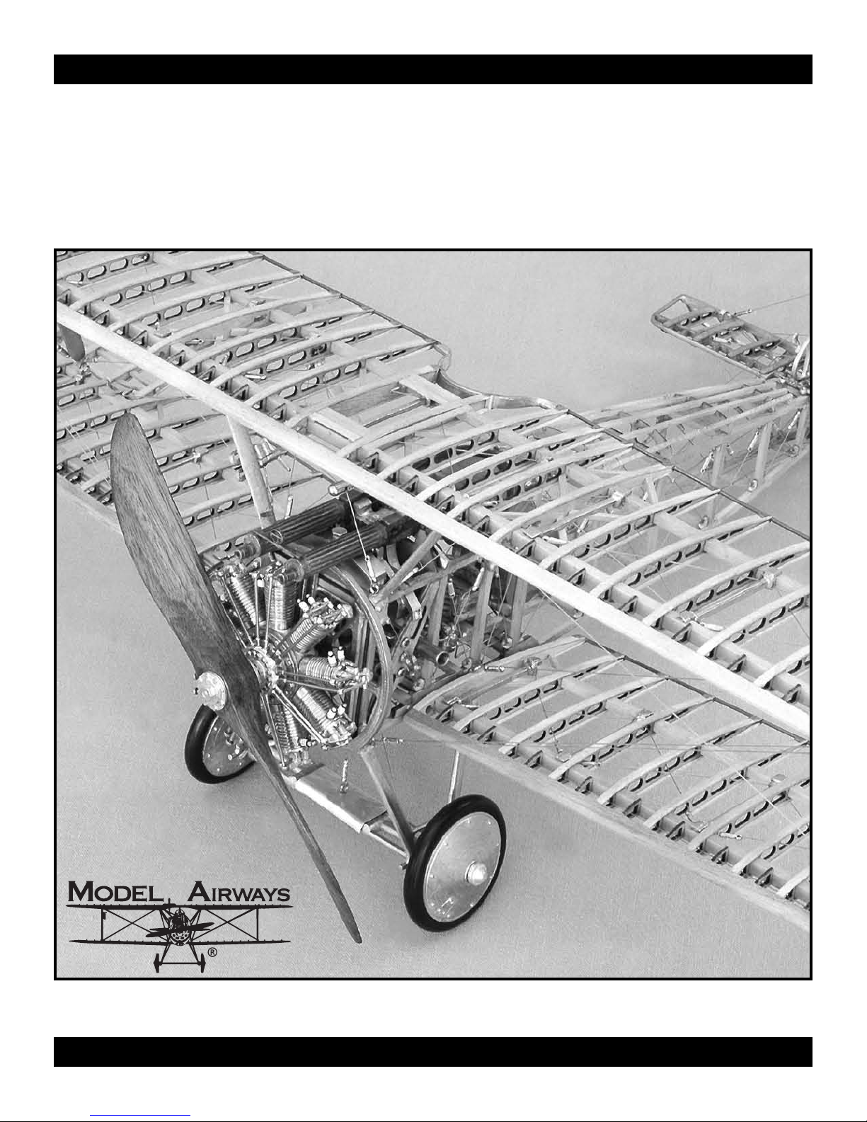
Model Airways SOPWITH CAMEL F.1, MA1030 Instruction Manual
INSTRUCTION MANUAL
MODELING THE
MODELING THE
SOPWITH CAMEL F. 1
SOPWITH CAMEL F. 1
✦
✦
WORLD WAR I BRITISH FIGHTER AIRCRAFT, 1917
WORLD WAR I BRITISH FIGHTER AIRCRAFT, 1917
Technical Characteristics
Scale: 3/4" = 1' (1:16)
Wingspan: 21" (534 mm)
Fuselage Length : 14-1/16""
(584.2 mm)
✦
✦
Manufactur
Model Airways Kit No. MA1030
Instructions and prototype by Kenneth H. Goldman
ed by Model Shipways, Inc. dba Model Expo • Hollywood, Florida
Sold by Model Expo, a division of Model Shipways, Inc.
http://www.modelexpo-online.com

HISTORY
HISTORY
T.O.M. Sopwith made his first solo flight in a Howard Wright Monoplane in 1910 and was forever hooked on aviation. A year later, after setting several records, he opened his own flying school. Not satisfied with other designers’ aircraft, he built his first biplane near the end of 1912, and at the beginning of 1913, The Sopwith Aviation Company
was in business. Combining his love of things nautical as well as aeronautical, his early production focused on float
planes. With the outbreak of the Great War, however, Sopwith’s efforts turned to the defense of the United Kingdom.
The company’s most famous creation was the F.1 Camel, so named after the humped fairing that enclosed its twin
Vickers machine guns each of which was fed by a disintegrating belt of 250 rounds. The prototype first flew in December 1916, and production models entered service in July 1917. The tight grouping of all the weight, including the
pilot, between the propeller and the center of the wings made the plane unforgiving in the hands of an inexperienced
pilot at low altitude but highly maneuverable at high altitude. Even with this late entry into combat, the Camel
accounted for 1,294 victories, more than any other Allied aircraft type. Surprisingly, less than 10% (503) of the total
production of 5,497 machines was actually accounted for by The Sopwith Aviation Co. The remainder were built
under license by Boulton & Paul Ltd. (1,550), British Caudron Co. Ltd. (100), Clayton & Shuttleworth Ltd. (575),
Hooper & Co. Ltd. (321), March, Jones & Cribb Ltd. (175) The Nieuport & General Aircraft Co. Ltd. (400),
Portholme Aerodrome Ltd. (300) and Ruston Proctor Ltd. (1,573).
1,342 of the aircraft were equipped with Clerget engines, the rest had either a Gnome, Le Rhone or Bentley. The 130
hp Clerget 9B-powered F.1 Camels had a wingspan of 28 feet and a length of 18 feet nine inches. The aircraft weighed
957 pounds empty and 1455 loaded and could reach a speed of 101 to 113 mph at 10,000 feet. This performance fell
off somewhat at altitudes between that and its absolute ceiling of 24,000 feet. Fluid capacity of 26 gallons of fuel and
5.75 gallons of castor oil allowed 2.5 hours of flying time. The rate of climb was five minutes to 5,000 feet and twelve
minutes to 10,000 feet.
Although a lively dispute continues as to whether Canadian Captain A.R. Brown shot down the Red Baron on 21 April
1918 or whether Australian machine gunners firing up from the trenches fired the fatal shot, there is no dispute that
Roy Brown was flying a Sopwith Camel when he chased von Richthofen’s Fokker Dr.1 triplane that fateful day. Among
the other successful Camel pilots was Captain Arthur Harris, later Air Marshal and architect of the World War II carpet
bombing campaign against the Third Reich, which earned him the nickname “Bomber Harris.”
The SOPWITH CAMEL model plans and kit were completed in 2005. The model was designed for Model Airways by
Microfusioni - modellisimo of Milan, Italy, owned by Luigi Volonté and son Bruno. Model plans and original Instructions in Italian were developed by Luigi Volonté. The text was rewritten in English and expanded by Kenneth H. Goldman, who also built the model.
Copyright 2006 by Model Airways, Inc., a division of Model Shipways, Inc., dba Model Expo • Hollywood, Florida
INDEX
INDEX
Technical Specifications ...................................Cover
History / Introduction / Credits..............................2
Before You Begin.....................................................3
Working with the Plans & Parts ..............................3
What You’ll Need to Start Construction ..................3
Painting & Staining the Model................................4
Stage 1: Building The Engine & Propeller............4-7
Stage 2: Building The Wings ...............................7-11
Stage 3: Building The Empennage.........................23
Stage 4: Building The Fuselage.........................13-15
Stage 5: Building The Engine Mount ....................16
& Plumbing
Stage 6: Building The Cockpit & Controls ......17-19
Stage 7: Epennage Installation & Cabling........19-21
Stage 8: Attaching The Lower Wing.................20-22
& Undercarriage
Stage 9: Attaching The Upper Wing, ...............22-25
Cabling & Bracing
Stage 10: Finishing Touches .............................26-27
More Great Model Airways Kits............................28
2

Before You Begin
The SOPWITH CAMEL kit is intended as a
structural, non-flying, model without any fab-
vering. It is about as close as you can
ric co
come to being able to hold the r
our hand. Most every detail of the real air-
y
craft has been included as model scale permits.
Britannia castings and laser-cut wood fittings
eliminate creating many parts from scratch,
however, some final finishing is required
before they are suitable for the model.
Before starting the model, carefully examine
the kit and study the plans. Every effort has
been made to present the construction stages
in a clear, logical sequence. Nevertheless, it is
recommended that you think several steps
ahead and check the plans accordingly during assembly. This will help clarify what you
are doing now and will ensure proper fit of
the sub-assemblies later. The instructions
will help, but a thorough knowledge of the
plans at the outset is essential.
Determine if all the listed parts are present.
Handling them will produce a better understanding of the kit's requirements and will
help you visualize how every piece will look
on the completed model.
small fittings and hardware, sort them into
labeled containers with lids to keep the parts
in and dirt out.
Although each Stage in the instructions
results in a completed sub-assembly, it is recommended that you begin at Stage 1 and
proceed in order to the finish. Certain modeling techniques are described in full when
they first appear in the sequence and only are
referred to in subsequent steps. Always complete one construction stage before moving
to the next. In addition to the construction
figures that accompany the instructions,
ocess photographs thr
pr
clarify construction. If things still go awry,
take a br
eak, then consider doing them o
View color photo on our website!
www.modelexpo-online.com
eal thing in
To avoid losing
oughout will help
ver.
Plans
ways SOPWITH CAMEL is
odel Air
The M
manufactured to a scale of 1:16 or 3/4" equal
to one foot. I
appear throughout this instruction manual,
five full-size plan sheets are provided. Each
plan sheet is drawn to the actual siz
model except for some areas that have been
enlarged to better sho
imensions can be lifted dir
D
size plans by using draftsman dividers, a strip
of paper laid on the plans on which you make
at dot indicating each end of a part, or simply
by laying wood strips directly on the plans and
marking where to cut them.
n addition to the Figures that
e of the
w detail.
ectly off the full-
Parts
A parts list is included in each of the construction stages, noting the par
ticular stage. A MASTER PACKAGING
par
PARTS LIST (separate from these instructions) is provided that lists the quantities
included in the kit. F
wire and rigging, one or several pieces are provided in the kit as noted on the master packaging parts list. These are identified both by size
and by the names of the aircraft parts that will
be made from them. This material must be cut
to length or shape according to plan dimen-
ven though Model Airways supplies
sions. E
enough extra wood to complete the model
before running out, it is recommended that
you plan to measure and cut the required parts
so as to minimize waste. That way you are covered if you make a mistake.
ts required for that
or wood strips, brass rod,
Cast Metal Fittings
These parts will require final finishing before
mounting on the model. Remove mold joint
flash with a #10 or a #11 hobby blade, then
file or sand with fine sandpaper. Some of the
holes through which other parts fit, such as the
small eyes of a turnbuckle, may have filled in
during the casting process. Carefully clean
these out using a drill bit or reamer and check
the fit of the other parts. To ensure good glue
and paint bonds to these parts, wash off the
remaining traces of the mold release agent. A
spray of ammonia window cleaner and gentle
brushing with an old soft-bristle toothbrush
does the job nicely. Thoroughly rinse the parts
and allow them to dry.
Necessary Construction Tools
-
ecom
The follo
mended for the construction
process. Modelers who have built before may
have their own favorites.
A.
blades
B. Files - Set of needle files
F
R
C. Clamps and Pins
D. Boring Tools
wing tools and supplies ar
Knives and saws
1. Hobby knife with No. 11 and No. 10
or saw
2. Raz
lat, fine-tooth, mill bastar
ound riffler file
1. Assorted Bulldog clips
2. Wooden clothespins
ubber bands
3. R
4. Package of T-pins
et of miniatur
1. S
2. Pin vise
tandard set of twist drills
3. S
d file
e drills (#60 to #80)
e r
iscellaneous
E. M
1. Tweezers (a few)
Small fine pointed scissors
2.
3. Miniature pliers
a. small round
b. flat nose
Wire cutters
4.
5. Mechanics rule graduated in 1/64"
6. Brass brush for polishing cast parts
7. Small block plane
. Sandpaper
F
#120 aluminum oxide paper for shaping wood
parts
et/dry silicon carbide paper for
#200 w
intermediate sanding
#400 wet/dry silicon carbide paper for fit-
tings and finishing
G. Glue
Yellow (tan) carpenter's glue for wood parts
Cyanoacrylate (CA or Super Glue) for metal
parts, metal to wood, and rapid assembly of
wood par
3. OPTIONAL
C
have to take something apart)
Cyanoacrylate Accelerator for an instant bond
Five-minute epoxy provides extra strength for
gluing fittings.
H. Building Board
A soft, but stiff board such as acoustic ceiling
tile or insulation wallboard to easily take
straight pins for holding parts during assembly. This soft board should be nailed or glued
to a hard board so it will be flat. You can use a
table, but a portable board is good for turning
it around to make the work easier. You will
also need assorted scrap lumber, as indicated
on Plan 05 to build some of the suggested
special jigs.
ts.
yanoacrylate De-Bonder (just in case you
(for shaping wing leading edges)
Setting Up The Plans
t is easiest to build flat subassemblies dir
I
on the full-siz
building boar
or plastic wrap
especially super glue. Although the waxed
paper or plastic wrap protects the plan
somewhat, you could accidentally glue the
protective sheet to the model parts, or even to
the plan itself.
An alternative, if you have a dedicated
modeling area, is to lay a sheet of glass over the
full-siz
glass, using tape and w
in position. I
for sharp edges on the glass.
e plans. P
d and cover it with waxed paper
. Be careful applying glue,
e plan sheet and build dir
f y
lace the plan on your
ectly on the
eights to hold the par
ou use this method, watch out
ectly
ts
3

Getting Started
Before commencing each stage of construction, have all the parts for that stage identified and ready to use. It helps to lay each
part on its corresponding location on the
full-size plan to facilitate identification as
ou proceed. Lightly sand wood parts as
y
required to remove any fuzziness and prepare
the castings par
ts as noted above.
Painting and Staining
Your Sopwith Camel model need not be
painted or finished at all. H
ommended that you seal the wood parts and
Britannia castings for protection. Due to the
owever, it is rec-
STAGE 1: BUILDING THE ENGINE AND PROPELLER
intricacy of the finished model, this is best
done as you go. Using carpenter’s glue on
raw wood allows the strongest bond, but
inevitable glue smears and r
wood essentially impervious to staining, and
end grain will stain darker than the rest. A
good compr
varnish onto completed wood subassemblies,
follo
color or darken the tone, followed by a finish
coat of varnish to even out the gloss. The
first, sealer coat, is especially important if
you use water base products.
Britannia castings parts may be left polished
or painted a steel or gunmetal color
suggested during constr
insulators can be painted white. Other fit-
omise is to airbrush or brush
wed by a tinted coat to even out the
uns leave the
, or as
uction. Sparkplug
tings, such as turnbuckles and instr
castings, can be painted black. Varying the
tones on the various parts will add a nice
contrast to the finished model.
The distinctive wicker seat back is provided
ritannia casting to simplify construc-
as a B
tion. You will need to paint this, after gluing
it to the seat, to give it an appropriate rattan
finish. A tan base coat followed by light and
dark washes will give you a good effect.
After you have shaped and finish sanded the
laminated propeller, you can achieve a more
authentic look b
mahogany and then building up two or
three thinned layers of varnish or shellac.
y staining it golden
uments
Although a counter-intuitive design by today’s standards, fixing the
propellers to a spinning engine on a stationary crankshaft simplified
cooling, had an excellent weight to horsepower ratio and allowed
greater flexibility in locating the aircraft’s center of gravity – affecting maneuverability - over the in-line engines of the time. One
drawback, however, was the pronounced gyroscopic effect that
pulled the aircraft to the right. To fly in a straight line, pilots had to
compensate for this by applying constant left rudder.
The Clerget rotaries provided improved speed control over the
Gnome and Le Rhone rotaries by replacing the standard “blip”
switch that temporarily grounded the magneto (killing the ignition)
with a selector switch that restricted the engine to run on 9, 7, 5 or
Parts List For Stage 1
WP129K-1.5
CLE02 Crankcase 1 Britannia casting
CLE03 Crankcase covers 2 Britannia castings
CLE04 Front propeller flange 1 Britannia casting
CLE05 Rear propeller flange 1 Britannia casting
CLE06 Camshaft box 1 Britannia casting
CLE07 Induction box 1 Britannia casting
CLE08 Igniter ring 1 Britannia casting
CLE09 Spark plugs 18 Britannia castings
CLE11 Cylinders 9 Britannia castings
Crankshaft tube 1 3/16" diameter x
1-1/2" brass tube
even 3 cylinders. Like the earlier rotaries, the Clerget spewed
unburned castor-oil from the exhaust, adding to the pilot’s discomfort. Pilots were issued a small bottle of blackberry brandy to counteract the smoke’s laxative effect.
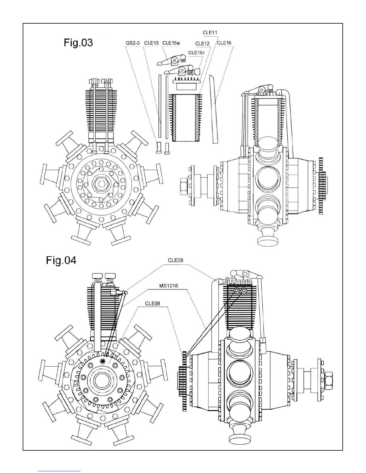
The completed engine subassembly slips onto the fixed crankshaft
at a later construction stage. Super glue and/or epoxy should be
used to assemble the parts. Care must be exercised with the many
small parts. Refer to Figures 01 through 05. For clarity, drawings
may show a single cylinder. It is a simple matter to repeat the assembly for the other eight cylinders. The key to success is to carefully
clean up all of the castings and then to dry fit everything before
applying glue.
Parts List For Stage 1
CLE12 Cylinder heads 9 Britannia castings
WP162-1.2 Valve lifters 18 15/16" x 1/16" d.
brass rods
GS2-3 Tappet seats 18 Small brass eyelets
CLE15i Intake rocker arms 9 Britannia castings
CLE15e Exhaust rocker arms 9 Britannia castings
CLE16 Induction pipes 9 Britannia castings
CLE17 Propeller 3 Laser-cut basswood
5/32" thick
WP1218 Ignition wires 9 cut from 72"
black thr
ead
Engine group:
Begin by attaching the front and back
ers (CLE-03) to the crankcase
crankcase co
(CLE-02). N
the castings to help y
one side in place, then make sure the bolts
heads line up on both covers before gluing
the second co
bly onto the crankshaft tube, which you must
cut from (WP129K-1.5) to ensure that the
engine parts line up properly, but do not glue
the cast par
Slip the nine cylinders (CLE-11) over the
pistons on the crankcase so that the pair
v
e tiny notches in
ote that ther
er in place. S
v
ts to the tube at this stage.
e ar
ou align the par
lip this subassem
ts. G
lue
-
ed
sparkplug holes all face the same way, perpendicular to the central axis of the
w hold the subassembly facing
crankcase. N
ou so that the spar
y
on the cylinder at the top
of the engine. Slip the camshaft box (CLE-
06) onto the brass sleeve and align it so the
paired depressions for the tappet seats (GS2-
3) are centered in front of each cylinder.
Looking at the top cylinder, the left hand of
each pair should be closer to you. Glue CLE06 against the crankcase. For the best fit of
the tappet seats (GS2-3) later on, use a 3/32"
twist drill to clean the 18 depr
CLE-06. F
o
kplug holes ar
.
inish up with a quick twist fr
4
e to the left
This is the fr
essions in
ont
om a
7/64" drill to bevel the edges. Be careful not
to drill too deep.
Refer to Engine Photograph 1 to align the
cylinder heads (CLE-12) on the cylinders
ou glue them in place. NOTE that
e y
befor
the two flats on the top do not match: the
larger one, with straighter sides, also has the
larger hole; it is for the intake rocker arm,
-
which goes to the side opposite the spar
plug holes.
central axis of the engine, which will set the
two holes at an angle to that axis. N
the intake rocker arms (CLE-15i) to the
cylinder heads so that the flanged pipe on
each goes to the r
The flats should line up with the
ear of the engine.
k
ext, glue

lip the induction box (CLE-07) onto the
S
brass tube at the rear of the engine. Referring
to Engine Photograph 2, holding an induction pipe (CLE-16) in place, flanged end
against a flat on the CLE-07, position the
flat on the induction bo
x so that the flat side
of the other end of the pipe meets the center
of the flanged pipe on the intake r
ocker arm.
Properly aligned, it will be at a slight angle.
Glue CLE-07 to the crankcase. Dry fit each
induction pipe and adjust the flat as neces-
y to fit against the pipe on each CLE-15i
sar
and glue them into place. F
each induction pipe that extends abo
ile off any part of
ve the
edge of the flanged pipe on parts CLE-15i.
lue the igniter ring (CLE-08) to the induc-
G
tion box so that the holes line up between
each pair of cylinders and the small gear faces
om the engine. Now glue the engine
away fr
subassembly to the crankshaft tube so that
one end of the tube is flush with the outer
surface of the small gear on the igniter ring.
Glue the exhaust rocker arms (CLE-15e) in
place on the cylinder heads. C
ut the 18 valve
lifters (CLE-13) from the provided lengths
of 1/16" brass r
od. It is suggested that you
cut them to 15/16" and then file them down
to achieve the best fit. Slide a tappet seat
(CLE-14) onto the brass r
od and glue into
place, referring to Engine Photograph 3.
Complete the engine gr
ignition wir
es (WP1218) from the igniter
oup by attaching the
ring to the spark plugs, referring to Engine
hotograph 4. Cut 18 4" lengths of black
P
thread. Feed each pair of threads through
one of the nine holes in the igniter ring and
tie them to the spar
kplug terminals. Alligator
clips or other small clamps can be used on
the thread ends that emerge from the hole to
eights to keep the threads taut as you
act as w
fix them and the knots with a drop of glue.
Trim off the excess thread and repeat the
process for the other eight cylinders.
Engine Photograph 1
5
6
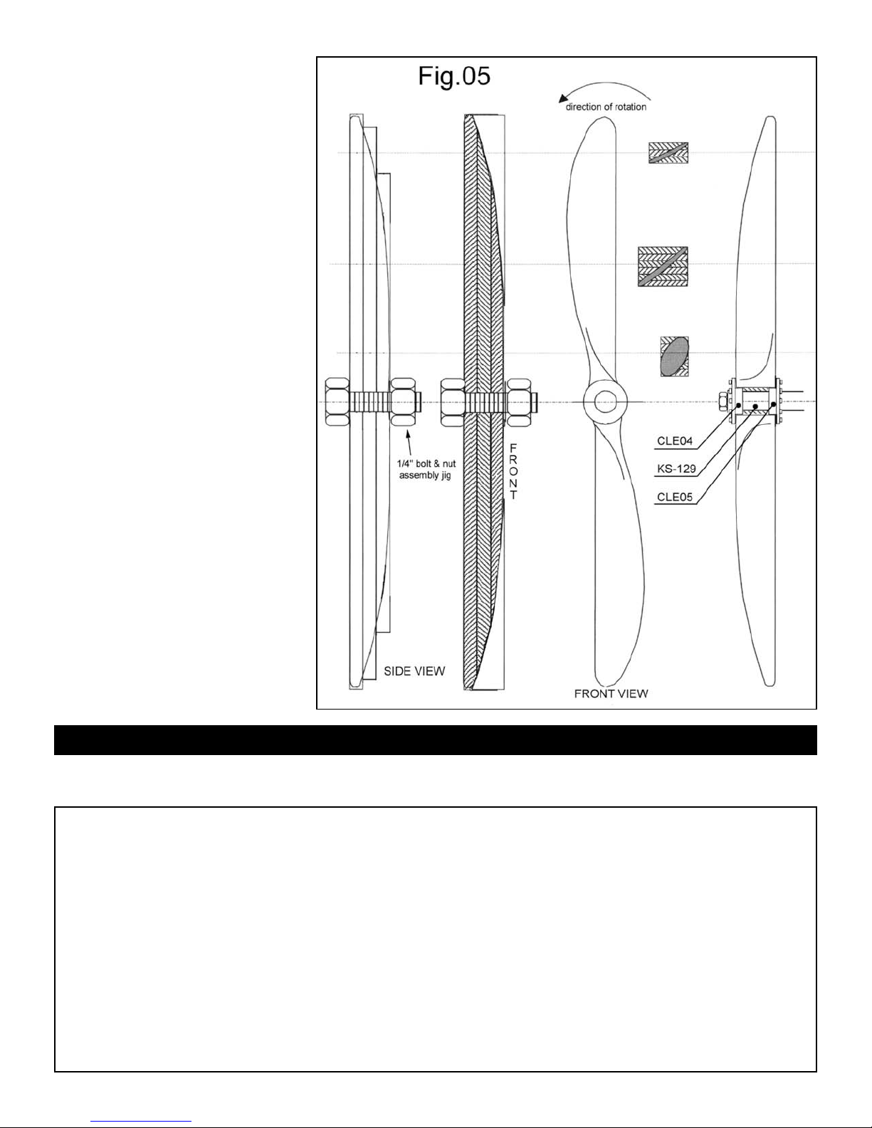
Propeller group:
Referring to Fig.05, laminate the propeller
layers (CLE17). Take care to stack the layers
in the correct order. When viewed from the
front in a vertical position, the stack goes
om longest to shortest with the shortest
fr
layer closest to you. Curved edges would
then be upper left and lo
diameter bolt and nut make a handy center
clamp that helps align the layers while the
glue dries.
Remove the bolt and whittle and sand the
propeller to its refined shape. The front of
the finished propeller curves toward the back
when viewed from the side. Begin with the
overall lengthwise curve, then proceed to the
cross-sectional shaping. This will result in a
curved leading edge and a straight trailing
edge after the final shaping. Shape the front
first, then the back to follow the front. Note
that the front surface is slightly convex and
the back is slightly concave.
When you are satisfied with the result, apply
a gold-mahogany stain. If using a water-base
stain you might have to lightly re-sand the
opeller with #400 paper to remove any
pr
raised wood grain, then apply a couple of
coats of varnish.
Attach the front (CLE04) and rear( CLE05)
flanges to the propeller. Make sure the front
and rear bolt heads/nuts line up before
gluing. Dry fit this assembly onto the
crankshaft mount. There should be a space
of about 1/16" between the rear propeller
flange and the camshaft box.
DO NOT glue the propeller to the
crankshaft mount until final fitting of the
engine to the completed aircraft. This will
allow you to make any needed adjustment so
the prop will clear the machine gun muzzles.
wer right. A 1/4"
STAGE 2: BUILDING THE WINGS
The upper and lower wings are built in essentially the same manner,
referring primarily to full-size Plan 03. The primary differences are
Parts List For Stage 2
CA
W01
Ribs 2 laser-cut plywood 3/64" thick
CAW02 Ribs 28 laser-cut plywood 3/64" thick
CAW03 Ribs 8 laser-cut plywood 3/64" thick
CAW04 Ribs 4 laser-cut plywood 3/64" thick
CAW05 Ribs 16 laser-cut plywood 3/64" thick
Ribs 4 laser-cut plywood 3/64" thick
W06
CA
Ribs
W07
CA
Nose ribs 50 laser-cut plywood 3/64" thick
W08
CA
CAW18 Wingtips 4 Britannia castings
op center trailing edge 1 Britannia casting
T
W19
CA
4 laser-cut plywood 3/64" thick
the center trailing edges and that the lower wing will be cut in two
and rejoined to create its correct dihedral angle.
CA
W20
Compression bars 15 Britannia castings
CAW21a/b
CAW22 Aileron horns 4 Britannia castings
CAW23
CAW24 Aileron pulleys 4 Britannia castings
CA
CA
CA
W042 Turnbuckles 36 Britannia castings
WP3603
7
Aileron hinges 12 each Britannia castings
Aileron cable anchors
W25
W38
W39
ession bars w/ey
Compr
wer wing joint
ont lo
r
F
Rear lower wing joint 1 Britannia casting
Rib caps
4 Britannia castings
es
ritannia castings
B
6
ritannia casting
B
1
1/32" x 3/32" basswood strips
Parts List For Stage 2 (continued)
WP3671 Leading edges 5/32" x 3/16" basswood strips
WP3648
WP3631 Rear spars 1/8" x 1/8" basswood strips
WP3625
WP3618 Rear aileron spars 1/16" x 1/16" basswood strips
WP1205 Rigging cable Metal-gray thread
WP161K
WP0976 Trailing edge bands 1/4" Adhesive copper tape
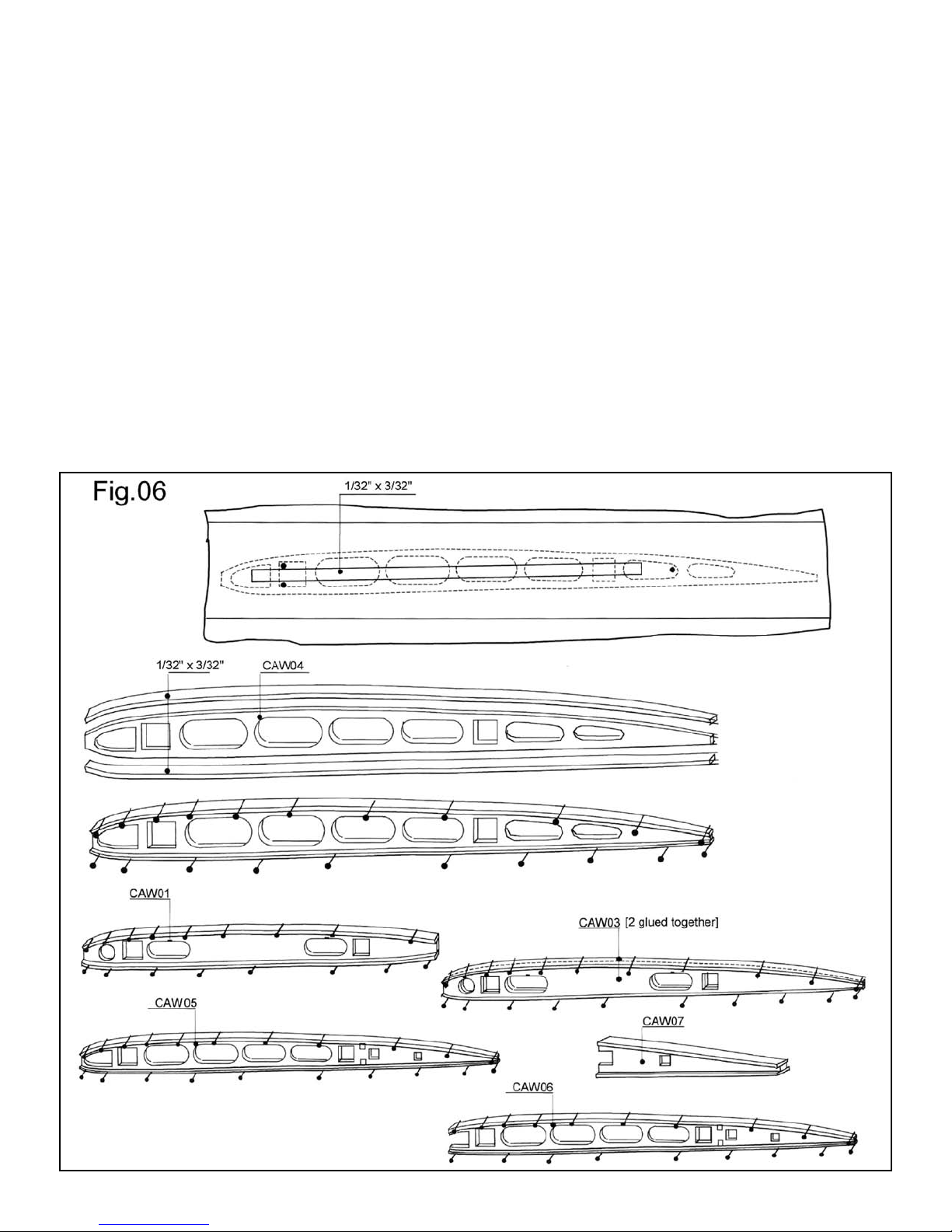
Wing ribs; rib caps:
After cutting loose all of the above referenced ribs, lightly sand them to remove surface char from the laser, then sort them by
number.
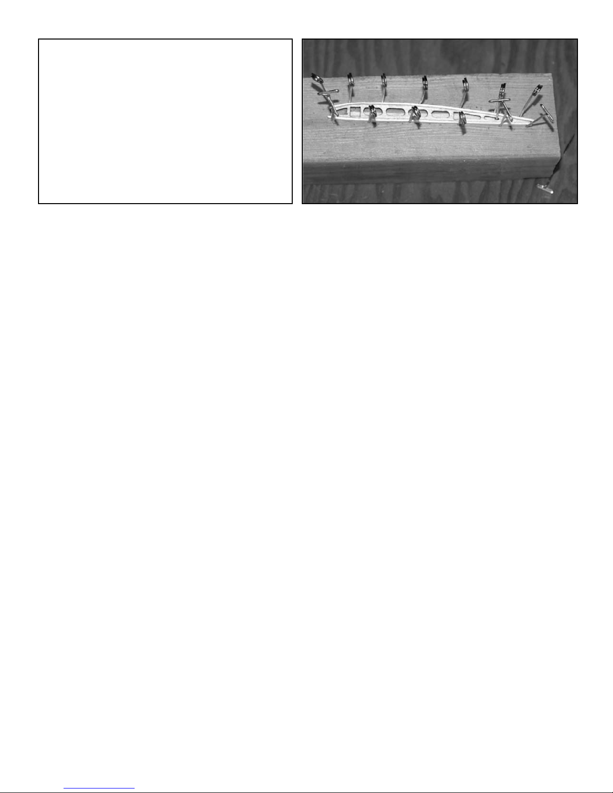
To facilitate making the cap strips overlap
ribs CAW02, 04, 05, 06 and 07 equally to
each side, make a simple jig by gluing a 2
1/2" length of the 1/32" x 3/32" rib cap
stock to a scrap block of soft wood, as in
Fig.06. Pin the rib to be glued onto the
strip through some of the cutouts, apply
carpenter’s wood glue to the rib edge and
use T-pins against the rib cap to clamp the
cap to the rib. Repeat for the opposite edge.
Note the photograph “Rib Pins”. Use of a
hair drier will speed up the process. The
“waist” on ribs CAW05 and CAW06 make
them particularly fragile, requiring extra
care when gluing on their cap strips.
The 8 parts CAW03 are laminated in pairs
to make 4 double-thick ribs befor
strips are glued on, and the 2 ribs CAW01
are glued flush to one edge of the cap strip
to make left and right capped ribs. Fig.06
shows the left hand one (looking from back
to front of the finished airplane). Therefore,
instead of using the jig, lay a piece of waxed
paper on the scrap wood to avoid gluing
those ribs to it.
Inserting the spars; leading edges;
nose ribs:
Slight variation in the provided wood strips
is to be expected, ther
spars, including the ailer
ribs and sand down the spars as needed to
attain a snug fit.
eferring to P
R
upper wing ribs, except CAW 06, 07 and
08 onto the fr
ear (1/8" squar
r
that the flush sides of ribs CAW01 face the
center of the wing. O
, glue the ribs into place using a small
up
brush and thinned wood glue.
nce the glue is dr
O
length and taper the ends outboard of the
first rib at each end to fit the narrower slot
in ribs CA
Front spars 5/32" x 5/32" basswood strips
Front aileron spars 3/32" x 3/32" basswood strips
ing braces
W
ing trailing edges 3/64" brass rod
W
nsert the aileron spars (3/32" and 1/16"
I
square stock) through the holes in ribs
W05 and 06, then glue and cut to
CA
length accor
rib CAW07, being careful to leave a gap
een it and the next inboard rib. This
betw
w the ailerons to move when they
will allo
later are cut free. Locate the wing angle
braces on P
e lumber and glue into place.
squar
Dry fit the leading edge lumber (5/32" x
3/16" x 24") against the front edge of the
ribs to check for uniform fit and to make
sure that the nose ribs (CAW08) will fit
snugly between the front spar and the leading edge. If necessary, use a long strip of
sandpaper, affixed to the same length
straight, flat piece of wood, to lightly sand
the leading edges of the ribs.
Trim spar ends and notch them, using a
ound needle file, to fit the wingtips
r
e cap
e test fit all of the
efor
on spars, to the
lan 03.1, slide all of the
ont (5/32" squar
e stock) spars. Make sure
nce ev
, cut the front spar to
y
W06 and glue those ribs in place.
e stock) and
ything is lined
er
CAW18. You also will need to file a notch
in the front spar rib CAW05 meets it. File
and bend the wing tip if needed so that all
ends make contact with the spars and ribs.
Glue the wing tip in place using CA and
repeat for the other wing tip.
Next, hold the 3/16" side of the leading
edge lumber in place to determine its proper length and wher
er the end of the wing tip casting – see
v
o
Fig.10. Before gluing the leading edge to
the ribs, locate the ailer
W24) on P
(CA
priate holes in the leading edge of the front
lue the leading edge in place and
. G
spar
taper the ends do
the last rib the leading edge attaches to.
lue the leading edge in place, 3/16" edge
G
against the ribs and car
rounded profile, as in the ribs cross-sections
lan 03. Car
on P
will speed up the pr
ribs in place. Now is the time to varnish
and tint the wing assembly
steps will expose unv
can be touched up with a brush.
, build the lo
inally
F
stage of completion and saw apart per
Plan 03.2.
ding to the plan. Attach aileron
lan T.03. Cut them from 1/16"
Rib Pins
e to cut notches to fit
on pulleys
lan 03 and drill the appr
wn to the wingtips fr
efully sand it to a
eful use of a block plane
ocess. G
w
lue the nose
. Although later
arnished edges, these
er wing to the same
om
Compression bars; pulleys;
trailing edge; visibility cutout;
rigging:
Glue the aileron pulleys in place using
CA glue.
Drill #75 size holes through both ends of
the compression bars (CAW20 and 25)
where the round flange meets the angle
bracket – see Fig.12 detail. Next, locate and
glue the compression bars in place, hanging
bars CAW20 from the top and attaching
CAW25 from the bottom, so the eyes point
down from the upper wing. All of the
compression bars are hung from the top in
the lower wing, which positions the eyes on
CAW25 pointing up. It is important that
the outboard upper and lower parts
CAW25 line up on the two wings, because
this is where the wing struts will attach.
To frame the visibility cutout in the upper
wing, first make sure that tabs that overlap
the spars of the center compr
filed down to a maximum of 1/32" thick.
Next cut four 9/32" lengths of 1/32" x
3/32" wood strip and glue these supports to
the front and rear spars edges, against ribs
CAW01, so that they extend from the outer
spar edges into the center space. Cut six
roughly 3/4" lengths of the same wood
and plank three of them onto each pair
of supports.
The easiest way to rig the wing bracing
o-
wires is to run a continuous length of
WP1205 thread from one end of the wing
to the other and then repeat the process to
create the X-pattern on Plan 03. Each time
you come to the front end of a compression
bar, slip a turnbuckle (W042) onto the
thread, through both holes, before running
the thread through the holes you drilled in
the compression bars. After stringing the
thread all the way to the opposite end of
the wing, secure the end, then gently
tighten the thread, working backward to
wher
e you started. At each front end of a
compression bar, slide a turnbuckle up to
the bar then secure the thread and turnbuckle with CA glue. A
compression bar secure the thread with CA
ession bar ar
t each rear end of a
e
8
glue. The procedure basically is the same
for the lo
rigged separately.
Although this rigging technique provides
generally acceptable results, the more
demanding modeler might pr
the thread through each turnbuckle eye in
lieu of using a continuous run.
The casting for the upper wing’s center
trailing edge (CAW19) requires some
adjustment for a good fit. C
at the ends so that they nestle between the
cap strips where they meet ribs CAW02.
Y
round to achieve the best fit. Sand the ends
of ribs CAW01 if needed, then glue curved
section of CAW19 to the end of the center
ribs so that 3/64" of the casting extends
beyond the trailing ends of ribs CAW02.
This provides an end seat for the 3/64"
brass rod which is used to make the wing’s
trailing edge. See Fig.11. Cut the brass rod
to length before attaching it with CA glue,
and leave a gap between the wing and the
wer wing, except each half is
ou might hav
e to file the pins out of
efer to knot
ut the long pins
ailerons – Plan 03. Finish off the trailing
y wrapping the joints with 1/2"
edge b
lengths of copper tape, cut to the width of
the rib cap strips. Use four 1/4" long copper strips to co
joints between ribs CAW01 and the center
trailing edge.
Carefully separate the ailerons from the
wings b
the rear wing spar and the front aileron
. Continue the cut through the wing tip
spar
casting and sand as needed. Referring to
Plan 03-1 and Fig.13 attach the hinges
W21 a&b. The gudgeon half (has hole)
CA
attaches to the r
half (has pin) attaches to the fr
spar. In order to lock the aileron to the
wing, arrange the hinges so the pintles of
the middle and outside hinges face the aircraft center line and that of the inside
hinges face toward the wingtips.
Locate the aileron horns CAW22 and the
aileron cable anchors CAW23 on the
ailerons as indicated in the drawings. The
ver the top and bottom
y sawing through the ribs between
ear wing spar and the pintle
ont aileron
horns angle forward and are placed atop the
upper wing and belo
Before gluing in place, notch the rib cap
where each part goes so that the vertical tab
snugs up against its laser-cut rib
w the bottom wing.
.
Joining the lower wing halves:
Create the lower wing dihedral by tapering
the bottom ends of the front and rear spars
so that when they are rejoined by parts
W38 and CAW39 they will lie flat with-
CA
in the cast joints and the underside of the
outermost ribs(CAW06) will be elevated
e the work surface. Reference
25/32" abo
Plan 03.3. The easiest way to ensure both
sides come out the same is to cut blocks of
the right thickness to hold up the wing
ends while you gently push down on the
center joints. Before gluing this together,
check that the space between the inside flats
of the innermost ribs (CAW03) is 1
13/16".
v
9
 Loading...