

Model Airways CURTISS JN-4D JENNY, MA1010 Instruction Manual
INSTRUCTION MANUAL
MODELING THE
MODELING THE
C
C
URTISS
URTISS
JN-4D J
JN-4D J
✦
✦
1917
1917
✦
✦
ENNY
ENNY
PREPARED BY BEN LANKFORD
FUSELAGE LENGTH: 20-1/2" (521 mm)
Technical Characteristics
SCALE: 3/4" = 1' 0" (1:16)
WINGSPAN: 32-1/2" (826 mm)
Manufactured by Model Airways
Division of Model Expo, Inc., Hollywood, FL
A
http://www
Model Airways Kit No. MA1010
.modelexpo-online.com
HISTORY
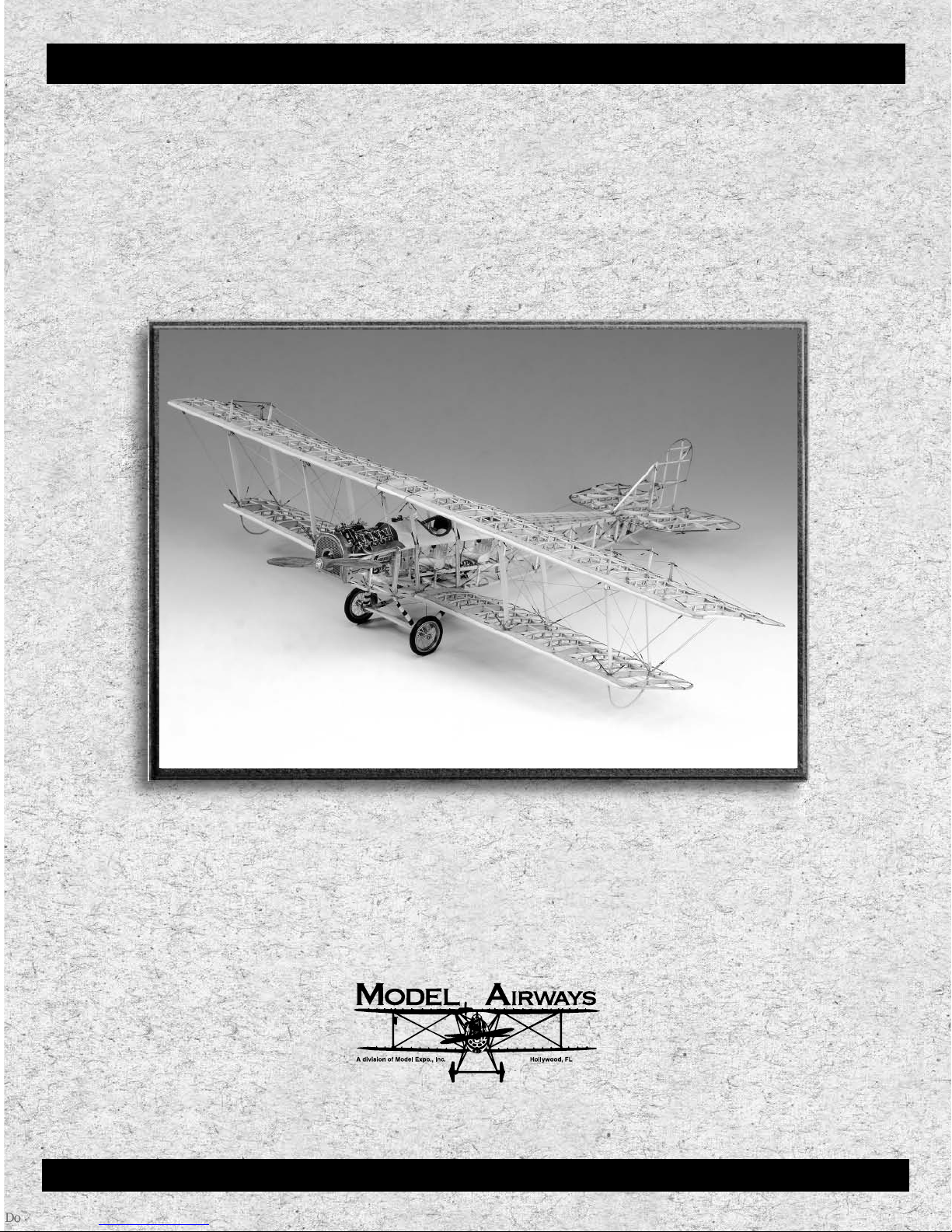
The
Jenny
biplane was introduced in 1916 and manufactured by
the Curtiss Aeroplane and Motor Corporation in Hammondsport,
Jenny
New York. The
a combat aircraft in World War I, but it became an important
trainer for pilots of the United States Air Service. The aircraft
became more famous after the war, being used as a barnstormer
and mail carrier. More than 6000 aircraft were built. The most
produced and most popular model was the JN-4D. More than
3000 were built. Some 1200 were produced in Canada and known
as Canuck JN-4CAN. About 1000 aircraft, mostly JN-4D’s, were
built by other US firms such as Springfield Aircraft Corporation,
St. Louis Aircraft Corporation, and Liberty Iron Works.
The
Jenny
has a wingspan of 43 feet 7 inches and weighs 1430
pounds. She flies at a speed of 75 mph, has an endurance of 2.5
hours, climbs to 2000 feet in ten minutes, and the service ceiling
is 11,000 feet. The aircraft is manned by a crew of two and is
powered by a Curtiss OX-5 in-line V8, water-cooled engine.
Thousands of these 90 HP engines, first manufactured in 1910,
were used in the
Besides the JN-4D model, there were other minor variations in
the models JN-1, 2, 3, 4, and models JN-4A, 4B, 4C, JN-4D2, and
JN-6H. Some had engines mounted with no engine-prop down
thrust, some had wings with less stagger (10" to 12" as opposed
to 16" on JN-4D). Other variations included a different stabilizer
shape, more dihedral in the wings (up to 4 degrees), and a longer
lower wing length. All in all, however, all models looked pretty
much the same.
The prototype JN-4D had ailerons on both wings, but the production models eliminated the lower wing ailerons. Earlier
name was coined from the JN series. Not
Jenny
and other aircraft.
aircraft used a wheel for controlling the rudder, but the D model
used sticks. Quite a few
flying today. Restored aircraft can be found in museums around
the country, including the Smithsonian Institution’s Garber
Preservation Facility) in Suitland, Maryland outside Washington,
DC; College Park Aviation Museum in College Park, Maryland;
Curtiss Museum in Hammondsport, New York; and the History
and Traditions Museum at Lackland Air Force Base in San
Antonio, Texas, to name a few.
To see a
a Jenny
Association) Aviation Foundation’s Paul Harvey Audio-Video
Center, in Oshkosh, Wisconsin. It has a good history and vintage
footage of the
The video highlights Ken Hyde’s restoration of a
scenes of its initial flights. The video has some wonderful color
photography of several restored
These scenes are from a 1989 reunion of these historic aircraft
held in Oshkosh. Lots of different color schemes and markings.
Several photos of a
throughout these instructions. Refer to the credits below for
more information about Ken Hyde himself.
For more flight scenes and close-ups, look for the 1975 movie of
The Great Waldo Pepper
outstanding video available entitled
To T h e A i r, V olume III
training in
including Minneola Field, NY, and Kelly Field in Texas. The
video was copyrighted in 1993 by Aerofilm.
Jenny
in action, an outstanding video is
. This is a 1989 film by the EAA (Experimental Aircraft
Jenny
Jenny’s
Jenny’s
as a military trainer and a barnstormer.
Jenny
. This video has early film shots of pilots
. The film was shot at various locations,
have been restored and are still
It’s Gotta Be
Jenny
with
Jenny
’s close up and in flight.
restored by Ken Hyde are shown
with Robert Redford. There is also an
World W ar I: America Tak e s
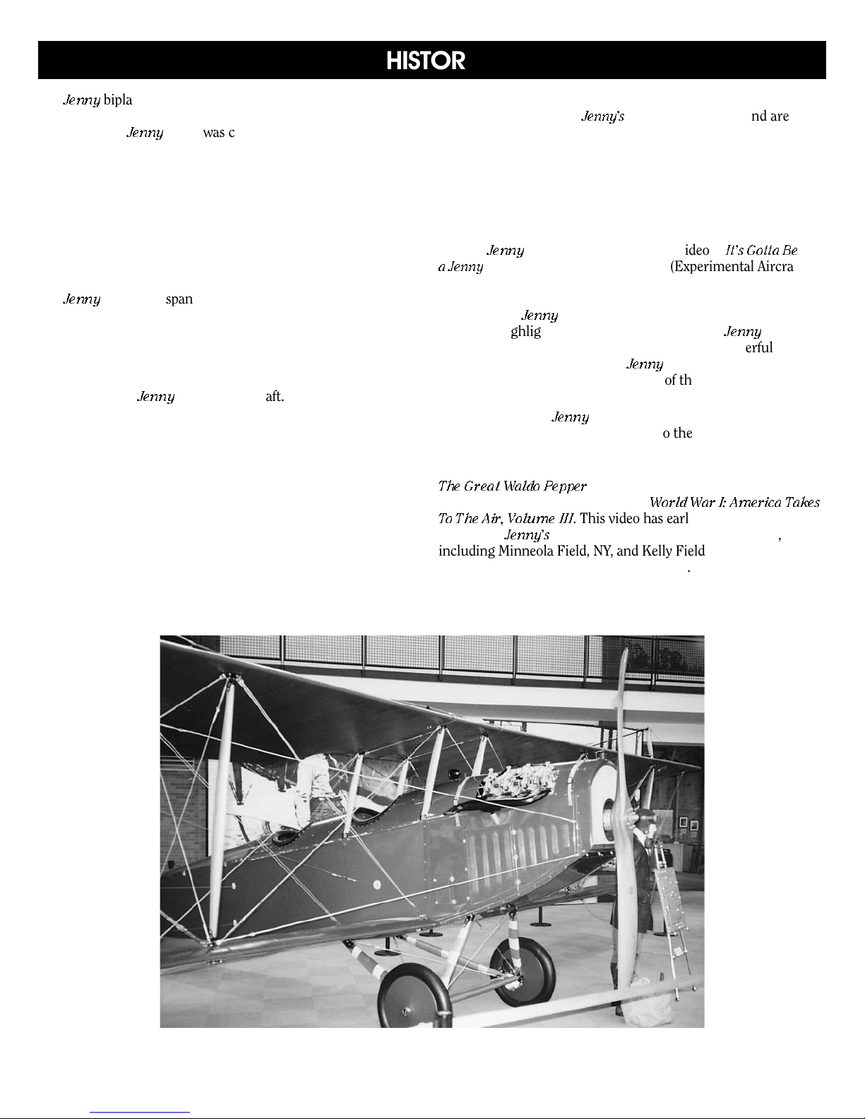
Ken Hyde’s restored Jenny at the Maryland Museum
2

TABLE OF CONTENTS
Technical Characteristics
History
Introduction and Credits
Before You Begin
Necessary Construction Tools
Working with the Plans and Parts
Painting and Staining the Model
Stage 1: Building the Wings
Stage 2: Building Vertical and Horizontal Stabilizers,
Stage 3: Building the Basic Fuselage
........................................................................................2
....................................................................5
1. The Plans ...............................................................................5
2. Parts.......................................................................................5
3. Kit Lumber.............................................................................6
4. Britannia Metal Parts..............................................................6
5. Photo-Etched Parts................................................................6
6. Rigging Cord ........................................................................6
7. Setting Up the Plans ..............................................................6
8. Part Identification and Readiness .........................................6
9. Bending Wood Strips.............................................................6
1. Preparing the Wing Ribs........................................................7
2. Setting Up the Wing Spars ....................................................7
3. Installing the Wing Ribs..........................................................8
4. Installing the Beam Webs and Web Blocks...........................8
5. Installing the Wing Tips, Trailing Edge,
and Upper Beam Flanges....................................................9
6. Installing the Small Wing Stringers .........................................9
7. Adding Miscellaneous Stiffeners
and Lower Wing Walk..........................................................10
8. Installing the Leading Edge Cover Sheet ...........................10
9. Installing the Cap Strips.......................................................10
10. Installing Wing Strut, Kingpost, and Wing Skid
Support Pads and Fittings ...................................................11
11. Building and Installing the Upper Wing Ailerons..................11
12. Installing the Aileron Control Sheaves.................................11
13. Installing the Drag Wires......................................................12
14. Installing the Fake Hinge Rods
in the Upper and L
15. Building and Installing the Lower Wing Skids .......................12
16. Building , Installing, and Rigging the Kingposts...................12
Building the Upper Wing Center Section
17.
18. Rounding the Leading Edge and Wing Tips.......................13
19. Building the Wing Struts .......................................................13
Rudder, and Elevator
1. Building the Vertical Stabilizer..............................................14
2. Building the Rudder ............................................................14
3. Building the Horizontal Stabilizer..........................................15
4. Building & Installing the Elevator .........................................15
5. Mounting the Vertical Stabilizer...........................................16
Building the F
1.
Building the Sides of the F
2.
3. Placing the Sides in the Building Jig....................................17
Building and Installing the Horizontal Struts
4.
ongeron Splices
L
5.
6. Building & Installing the Tailpost ..........................................18
Installing the F
7.
Plates and Engine Bearers ..................................................18
ower Wings............................................12
uselage Jig
................................................................
ront and Side Nose
............................................Cover
......................................................4
............................................5
.......................................5
.......................................6
................................................7
............................
..........................................14
.............................16
....................................................16
uselage
......................................
.........................17
13
17
18
Stage 3: Building the Basic Fuselage (continued)
8. Installing the Cockpit Floor Board Supports
and Floor Boards ................................................................19
9. Installing the Longitudinal Side Seat Rails............................19
10. Installing Forward and Rear Cockpit Instrument
Panels, and Shelf Behind Rear Cockpit ..............................19
11. Installing the Fuselage Strut Clips........................................20
12. Installing Cross Brace Wires.................................................21
13. Building and Installing the Turtleback..................................21
14. Installing the Step Plate.......................................................21
Stage 4: Installing Cockpit Controls and Seats,
1. Installing the Joysticks and Other Flight
2. Building and Installing the Seat Supports,
3. Rigging More Fuselage Cross Brace Wires .........................23
Stage 5: Building and Installing the OX-5 Engine,
1. Assembly and Installation of the Fuel Tank .........................24
2. Building the OX-5 Engine ....................................................25
3. Installing the Engine and Radiator......................................28
4. Installing Engine Piping, Tubing,
5. Rigging Final Fuselage Cross Brace Wires ..........................30
6. Building and Installing the Prop...........................................30
Stage 6: Building and Installing the Landing Gear
1. Installing the Tail Skid and Supports.....................................30
2. Building and Installing the Landing Gear............................31
Stage 7: Installing the Cockpit Cowl, Wings,
1. Installing the Cockpit Cowl, Windshields,
2.
3. Rigging the Rudder and Elevator Control Wires .................34
4. Installing and Rigging the Upper Wing
5.
6. Installing the Interplane Wing Struts
7. Rigging the Interplane Strut Cross Brace Wires,
8. Rigging the Aileron Control Wires........................................37
Finishing Touches
Bibliography
Photos of Model Air
and Additional Rigging
Control Fittings ....................................................................22
Seats, and Rail Cross Strut...................................................23
Radiator, Fuel Tank,and Prop, and Final
Rigging of Cross Brace Wires
and Control Linkages..........................................................29
and Tail Skid
Stabilizers, Rudder, and Elevator,
and Completing the Rigging
and Cockpit Edging ...........................................................33
Installing the V
Rudder
Center Section and Struts
Installing the L
and Upper Wings ................................................................35
Flying Wires, Landing Wires, Drag Wires, and
Kingpost Wires
ertical and Horizontal Stabilizers
, and Elevator..........................................................33
ower Wings
..........................................................................38
A Division of Model Expo, Inc., Hollywood, FL
.........................................................30
..................................................
...................................................
.....................................................................
.................................................................37
ways’
Jenny
©2002 Model Airways, Inc.
.....................................22
...........................24
..........................33
,
......................................
34
35
36
39
3
C
URTISS
C
URTISS
INTRODUCTION
MODELING THE
MODELING THE
JN-4D J
JN-4D J
ENNY
ENNY
✦
✦
1917
1917
PLANS AND INSTRUCTIONS BY BEN LANKFORD, VIENNA, VA
PROTOTYPE MODEL BY BOB WERNER, HOLLYWOOD, FL
Model Airways developed its
The design is based on factory drawings of
along with historical photographs, and photographs of
restored
are still flying today. Because of varying dates on many of the
references, and knowing that changes were made over a period of time, the design depicted by Model Air
represent any one particular aircraft. Most modifications
found in the various references were minor detail changes,
so the overall design is representative of a typical
Many thanks to the subscribers of the
E-mail List
the aircraft. The Internet home page address for the list is
http://www.pease1.sr.unh.edu/1/index.html, and the site is
Jenny’s
in museums and private owned aircraft that
for their assistance with various details of
Jenny
kit between 1999 and 2001.
Jenny
ways may not
World War I Model
aircraft,
Jenny
.
✦
✦
maintained by Allan Wright. You will find some great information and a gallery of some fine WWI models on these pages.
The home page provides instructions for joining the mailing
list if you are interested.
Thanks also to Ken Hyde from Warrenton, VA, an expert builder
and restorer of full-size antique aircraft, including the
Ken answer
oping the kit design. Ken, who is 61 years of age at this writing,
is a former American Airlines captain and Boeing 727 pilot.
Ken’s interest in antique planes obviously came from his father,
John “Captain Johnny” Hyde, a barnstormer in the early 1900s.
Ken’s latest project is a replica of the Wright 1903 Flyer, which
he intends to fly at Kitty Hawk at 10:35 a.m., December 17,
2003, as the Wright brothers did 100 years earlier.
ed many questions that had me puzzled while devel-
Jenny
.
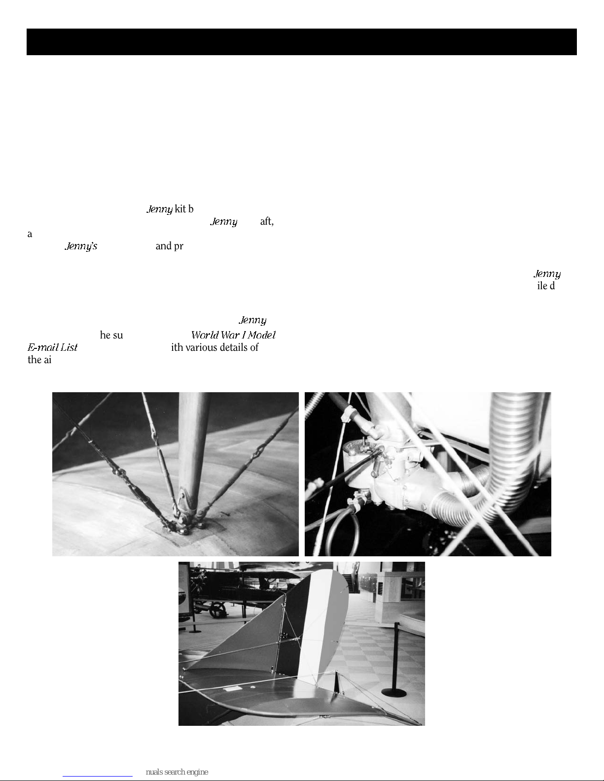
Clockwise from upper left: Interplane Wing Strut Fitting, Carburetor, and Tail Surface
and Rigging, as they appear on restored examples of the Jenny airplane
4
Before You Begin
The
Curtiss JN-4D Jenny
is an interesting
aircraft and makes a splendid model. The
kit is intended as a str
uctural model without any fabric covering. Most every detail of
the real aircraft has been included as model
scale permits. While your model structure
will be glued together, the original real aircraft had little glue if any. Most of the wooden structure was joined with many small
wood screws and metal clips. However,
some of the restored
Jenny’s
now use glue
in addition to the screws, since better glue
is now available.
Britannia, photo-etched metal, and wooden
fittings eliminate creating many parts from
scratch. However, some require final finishing before they are suitable for the model.
This is especially true for the britannia castings and will be discussed later.
Always complete one construction stage
before moving to the next. When things
go awry, consider doing them over.
Necessary Construction Tools
The following tools and supplies are recommended for the construction process.
Modelers who have built before may have
their own favorites.
A. Knives and Saws
1. Hobby knife with No. 11 blades
2. Razor saw or jeweler’s saw
B. Files
Set of needle files
C. Clamps and Pins
1. Alligator clips (some with and some
without teeth)
2. Wooden clothespins (craft shops have
small versions of the design)
Rubber bands
3.
4. Package of straight pins or florist pins
with plastic heads
Boring T
D.
1. Set of miniature drills
2. Pin vise
Miscellaneous
E.
1.
2. Tweezers (a few)
3.
4. Miniature pliers
5.
F. Sandpaper
Fine and medium grit garnet or aluminum
oxide sandpaper (#100 to #220), and
#400 wet-or-dry paper for fittings and
final wood sanding
Glue
G.
White glue, Carpenter’s wood glue (yellow in color), and Cyanoacrylate glue
(super glue) can be used for most of the
ools
ack hammer
T
Small fine-pointed scissors
a. small round
b. flat nose
Wire cutters (for cutting steel and
brass or copper wire, rod, and strip
metal)
model. Five-minute epoxy provides extra
strength for gluing fittings. The best super
glue for most applications is a medium
viscosity gap-filling type. The watery thin
type is recommended to fill a narrow
crack by capillary action.
H. Power Tools
While not really necessary, one power
tool would be advantageous for this kit.
The kit contains several sizes of steel
music wire that is extremely hard. A
Dremel or other rotary tool fitted with a
small fiberglass-reinforced cut-off wheel
is ideal for cutting off and flattening the
ends of steel music wire.
I. Building Board
A soft but stiff board, such as acoustic
ceiling tile or insulation wallboard, to easily
take straight pins for holding parts during
assembly. This soft board should be
nailed or glued to a hard board so it will be
flat. You can use a table, but a portable
board is good for turning it around to make
the work easier.
Working with the Plans & Parts
Before starting the model, carefully examine the kit and study the plans. First, determine if all the listed parts are present.
Handling them will produce a better understanding of the kit’s requirements. Try to
visualize how every piece will look on the
completed model. Also, determine the
building sequence – what must be done
first – ahead of time. The instructions will
help, but a thorough knowledge of the plans
at the outset is essential. Be especially
aware of when to rig the many brace wires
in the fuselage. There are a lot of parts that
must be added inside the fuselage. The
brace wires would get in the way if rigged
too soon.
To avoid losing small fittings and hardware,
sort them into labeled boxes or compartments.
These should have lids to keep out dirt.
1.
The Plans
Six plan sheets are provided:
1. Laser-Cut Wood Patterns and
Fitting Sketches
Assembly
Upper and Lower W
2.
and Details
3. Basic Fuselage Assembly and Details
4. Tail Surfaces and Landing Gear
Assembly and Details
OX-5 Engine and Cockpit Controls
5.
Assembly and Details
Component
6.
Details
Model Airways’
Assembly and Rigging
Jenny
to a scale of 3/4" = 1' 0" (1:16). Each sheet is
drawn to that scale except areas enlarged to
show detail. Most of the enlarged details are
double scale, and designated 2X (1-1/2" =
1'0"). Most dimensions can be lifted directly
off the plans by using draftsman dividers or
a “tick” strip (piece of paper such as an
adding machine roll). Lay the paper strip
ing
kit is manufactured
over the plan, carefully mark the item’s
length with a sharp pencil, then transfer the
marks to the wood.
Because these are model building plans,
actual measurements were converted to
model inches. For comparison, 1/16" on the
model is equal to 1" on the real aircraft, 1/8"
is 2", and so on. The table below compares
full-size dimensions with scale model inches
and millimeters:
SCALE CONVERSION TABLE
Full Size Model Scale Model Scale
Inches Inches Millimeters
1/4" 1/64" 0.40mm
1/2" 1/32" 0.79mm
3/4" 3/64" 1.19mm
1" 1/16" 1.59mm
1-1/4" 5/64" 1.98mm
1-1/2" 3/32" 2.38mm
1-3/4" 7/64" 2.78mm
2" 1/8" 3.17mm
2-1/4" 9/64" 3.57mm
2-1/2" 5/32" 3.97mm
2-3/4" 11/64" 4.37mm
3" 3/16" 4.76mm
6" 3/8" 9.53mm
9" 9/16" 14.29mm
12" 3/4" 19.05mm
2. Parts
Laser-cut wood parts, photo-etched parts, and
britannia castings are designated by a letternumber (such as
W1, F4, R2
sketches. A part noted such as
would indicate a right or left hand part. You
may also see some similar parts labeled, for
example,
R3A
and
R3B
generally in the following letter categories:
C
– CONTROLS: AILERONS, RUDDER,
ELEVATOR
E
– ENGINE, ENGINE PIPING, ENGINE
CONTROLS, RADIATOR, FUEL
TANK, PROPELLER
F
– FUSELAGE
L
– LANDING GEAR, T
RIGGING FITTINGS COMMON TO
R
–
VARIOUS LOCATIONS
ABILIZERS, RUDDER, ELEVATOR
S
– ST
WINGS
W
–
Wood strips and sheets, rod, wire, tubing,
rigging cord, and similar parts which must
be cut from longer pieces have no letter designation. Rather, only the dimension of these
items is shown on the plans.
A parts list is included in each of the construction stages, noting the parts required
for that particular stage. A
ts List
Par
(separate fr
is provided that lists the quantities included
in the kit. For wood strips, sheets, r
tubing, and rigging, one or several pieces ar
ovided in the kit as noted on the master
pr
packaging par
ts list. Each of these have been
assigned a Model Expo (Model Airways) WP
stock part number. These parts must be cut
to length or shape according to the dimensions shown on the plan.
) on plans and
L2R
or
L2L
. Parts are classified
AIL SKID
Master Packaging
om these instructions)
e,
od, wir
e
5
3. Kit Lumber
Strips and sheets of solid basswood or birch
plywood are supplied in the kit. Sort the
wood in the kit by thickness to save time.
After selecting and cutting what you need,
return the remaining stock to the proper
thickness and wood-type pile. Don’t worry
about using a piece for one item intended for
another. Model Airways supplies enough
extra wood to complete the model before
unning out.
r
4. Britannia Metal Parts
These parts will require final finishing before
mounting on the model. First, remove mold
joint flash with a #11 hobby blade, then file
or sand with fine sandpaper. Clean out any
holes using a drill bit or reamer. Some of the
smaller holes may not be completely formed.
Also, if another part must fit in the hole,
ream the hole if necessary for the parts to fit.
Wash fittings in dishwashing liquid and
warm water to remove traces of mold release
agent and the body oils your fingers deposit.
Allow to dry thoroughly.
5. Photo-Etched Parts
Cut the sprues off the parts with a sharp
hobby blade on a hardwood backing, or use a
sprue cutter. File any remaining sprue to
smooth out the part. Some photo-etched
parts must be bent to conform to the shape
shown on the plans, and lengths or configuration may be modified for the same part to
fit different locations. Bend parts using flat
nose or needle nose pliers. Don’t try bending
with your fingers.
6. Rigging Cord
On the real aircraft, the flying and landing
wire rigging and cross brace wires are 1/8"or 5/32"-diameter stranded steel wire. For
the kit, however, gray nylon cord is provided to make it easier to rig. All of the cord
should be beeswaxed to protect it and cut
down fuzz.
7. Setting Up the Plans
Build the wings, vertical and horizontal stabilizers, elevator, and fuselage sides directly
on the plan. Place the plan on your building
board and cover the plan with waxed paper
or plastic wrap. Be careful applying glue,
especially super glue. Although the waxed
paper or plastic wrap pr
what, you could accidentally glue the pr
tive sheet to the model par
otects the plan some-
otec-
ts, or even to the
plan itself. Plastic wrap is really a bear to
remove if it is accidentally glued to the
model with super glue. Use small applicators
such as a commercial Microbrush or toothpick for applying the glue. You don’t need a
lot of glue for the aircraft’s fragile parts.
8. Part Identification and Readiness
All the laser-cut wood, britannia castings,
and photo-etched copper and aluminum
parts can be identified by the patterns and
sketches shown on Plan Sheet 1.
Before starting each stage, have all the parts
required for the stage, such as laser-cut
parts, britannia castings, photo-etched parts,
stripwood, rod, and rigging, identified and
ready to use. Sand wood parts as required
to get rid of any fuzziness and prepare the
castings and photo-etched parts as noted
in Paragraph 4 and 5 above.
9. Bending Wood Strips
During the process of building the model,
you will be advised to heat-bend some wood,
such as fuselage longerons, wing tips, and
wing skids, to conform to a specific curve. A
good way to do this is to use an aluminum
tip with a flat end filed to a 45-degree angle.
Fit the tip in a 20- to 30-watt soldering iron.
First, soak the wood in cold water for 5 or 10
minutes. Remove the wood and let it sit and
dry out a bit for another 5 minutes. It won’t
completely dry out. Then take the soldering
iron an press on the wood, moving along
bending the wood to shape as you go. If
necessary, press over a form shaped to the
curve. The heat applied will easily bend the
wood, and the formed shape will remain after
the wood is dry.
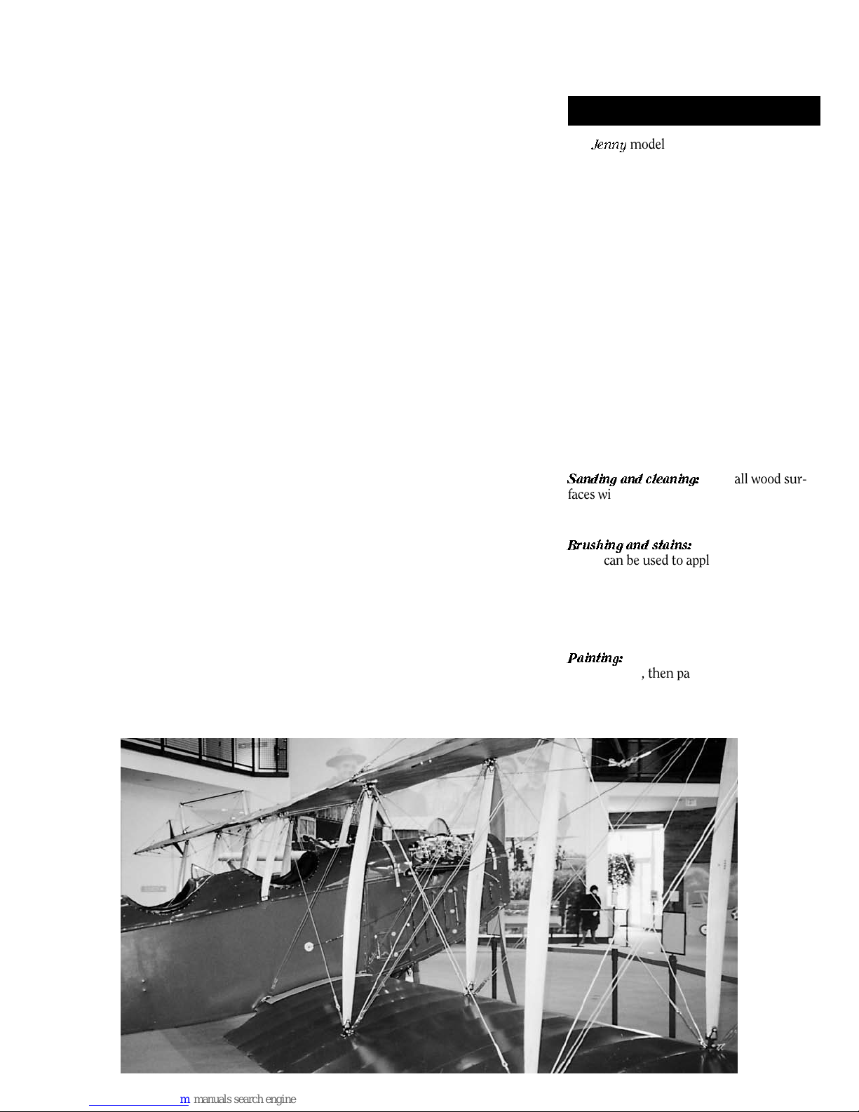
Painting & Staining the Model
The
Jenny
model need not be painted or finished at all. However, it is recommended that
you stain the wood parts and seal the britannia castings for protection. A light tan stain
on all wooden parts will help to make the
entire structure uniform in color.
Some parts could be painted, such as the
radiator and the fuselage cockpit cowl. This
would add a nice contrast to the otherwise
unpainted model. Since many color schemes
were used on various models, you will need
to do a little research on your own for proper
colors. You could also paint fittings such as
wing strut fittings and fuselage clips copper
color or black for contrast. If black is your
choice, consider using Blacken-It, a chemical
rather than paint. Steel rod represents steel
tubing on the real aircraft. These can be left
as is or painted a light gray color. Cast cockpit fittings can also be painted gray or just
varnished.
Sanding and cleaning:
faces with 220-grit dry sandpaper, followed
by 400-grit, and wipe off all dust thoroughly.
A tack rag would be helpful.
Brushing and stains:
brush can be used to apply stain to the parts.
Model Shipways or Minwax brand stains are
excellent for staining. For the castings, a
clear flat finish is suggested. This finish
could also be applied over the stained wood
parts as added protection.
Painting:
If parts are to be painted, use
a primer first, then paint. Any of the model
paints are satisfactory. For this model,
flat paints will pr
gloss paints.
Sand all wood sur-
A soft artist quality
obably look better than
View of
wing
uts
str
on
Ken
s
Hyde’
restored
Jenny
6
Plan Sheet 2 shows all the details for con
structing the wings, wing struts, and rigging
drag wires within the wings. In addition,
refer to Sheet 6 and Stage 7 for rigging the
kingposts on top of the upper wing that can
be done during this stage if desir
ed. The
following parts are required for this stage:
Laser-Cut Wood Parts
Upper wing ribs – 2 of W1
Upper and lower wing ribs – 4 of W2
Upper and lower wing ribs – 22 of W3
Upper and lower wing ribs – 12 of W4
Upper wing ribs – 10 of W5
Upper wing ribs – 6 of W6
Upper and lower wing ribs – 4 of W7
Lower wing ribs – 2 of W8
Lower wing ribs – 2 of W9
Upper wing ribs – 2 of W10
Lower wing ribs – 2 of W11
Upper wing ribs – 2 of W12
Aileron ribs – 4 of W13
Aileron ribs – 16 of W14
Center section ribs – 1 of W15
Center section ribs – 2 of W16
Center section wing struts – 4 of W17
Interplane wing struts – 8 of W18
Kingposts on upper wing – 4 of W19
Lower wing handhold blocks – 2 of W23
Wing building jig shims – 20 of W24
Britannia Castings
Aileron control horns – 4 of C1
Aileron control cable sheaves – 4 of C3
Aileron control cable sheave bodies –
4 of C4
Wing strut end fittings – 20 of W20
Wing skid end fittings – 4 of W21
Photo-Etched Copper Parts
Single eye rig fittings for drag wires
and kingpost wires – 128 of R1
Double eye rig fittings for aileron
control horn brace wires – 6 of R2
Drag wire and kingpost wire turnbuckles –
54 of R3A(short)
Wing wire rigging plates at struts –
20 of W22
Wood Strips
Rib vertical web stiffeners and cap strips –
0.020" x 1/16"
Wing strut and kingpost support pads –
0.020" x 1/8"
Stringers and miscellaneous wing stiffeners – 1/32" x 1/32" and 3/64" x 3/64"
Front beam flanges, and shims for wing
building jig setup – 1/32" x 3/32"
Rear beam flanges – 1/32" x 1/8"
Front beam webs, and web blocks at
compression ribs – 1/32" x 5/32"
Support stringers for lower wing walk and
wing tip stiffener – 3/64" x 3/64"
Rear beam webs, and web blocks at
compression ribs – 3/64" x 1/8"
Wing tips – 1/16" x 3/32"
Aileron leading edges – 1/16" x 5/32"
Upper wing rear web in way of ailerons –
5/64" x 1/8"
Wing skids – 3/32" x 3/32" flexible
beech wood
(cut to length as required)
STAGE 1:
Front beam web between first two ribs
inboard and center section – 3/32" x
5/32"
Leading edge – 3/32" x 3/16"
Rear beam webs between first two ribs
inboard and center section – 1/8" x 1/8"
Blocks (to be carved) at leading edge
wing tips and handholds – 3/16" x 5/16"
W
ood Sheet
Leading edge cover sheet and lower
wing walk – 1/64" plywood
Steel Rod
Wing trailing edge and struts between
kingposts – 1/32"-diameter
Fake wing hinges at center wing section
and fuselage – 1/16"-diameter
Brass Rod
Pins for kingposts – 1/32"-diameter
Brass Strip
Aileron fake hinges – 1/64" x 1/16"
Self-Adhesive Copper Tape
BUILDING THE WINGS
(cut to length as required)
(cut to length as required)
(cut to length as required)
(cut to length as required)
(cut to shape as required)
Bands securing trailing edge to ribs
and stiffeners
Rigging Cord
Drag wires in wings and kingpost wires –
0.010"-diameter gray nylon cord
Wrapping cord for splices – 0.008"
diameter black nylon cord
(cut to length as required)
1. Preparing the Wing Ribs
All wing ribs are laser-cut. For your information, the airfoil is an Eiffel 36. There are several different types of ribs, such as solid
compression ribs, where the drag wire fittings are located, basic ribs with lightening
holes, shorter ribs in the upper wing center
section in way of the upper wing ailerons,
and the aileron ribs. The outboard rib near
the wing tip is a solid rib, more narrow than
the others since the wing tapers at the tip.
The inner most rib on each wing panel is
thicker than the others.
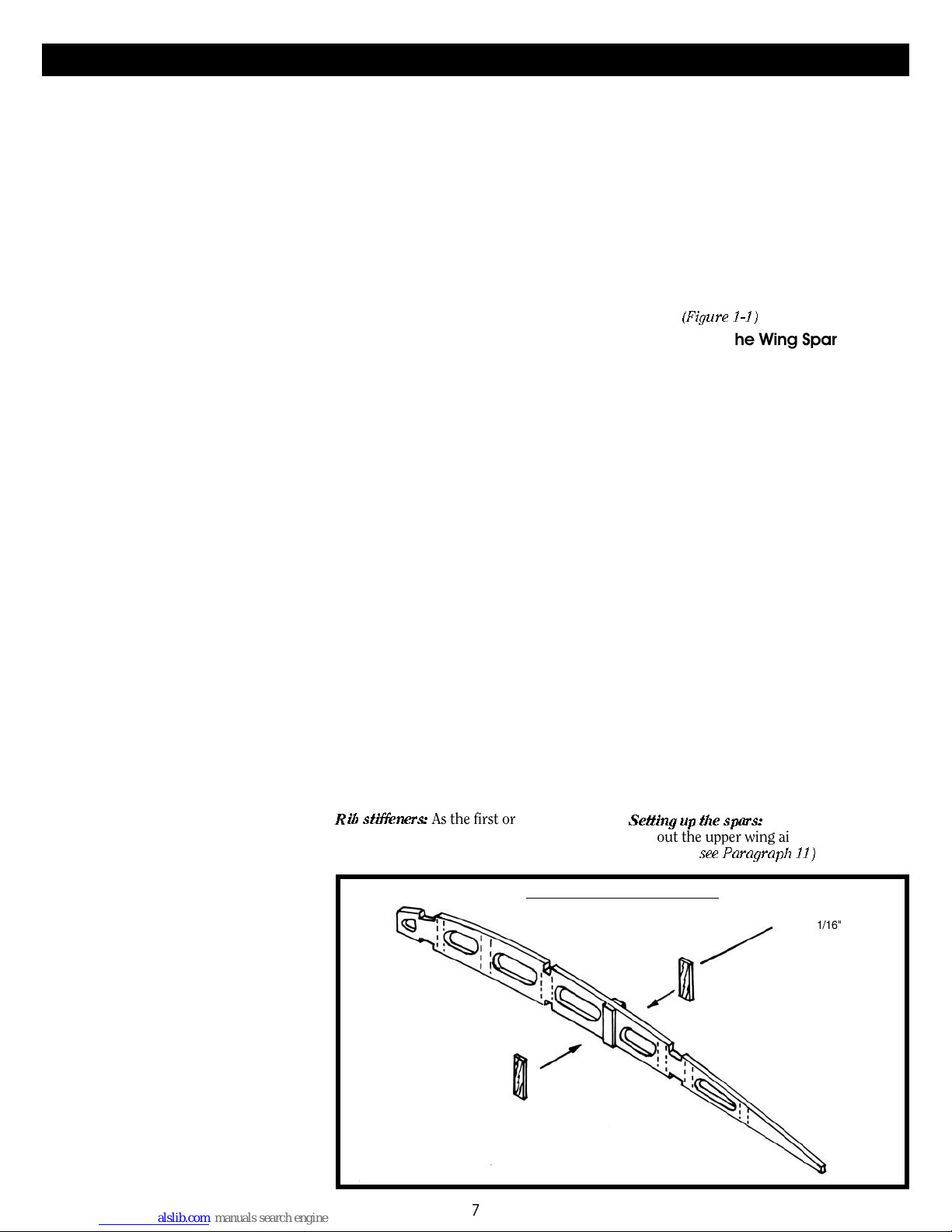
Rib stif
feners:
As the first or
der of business,
glue the vertical rib stiffeners on each side
of ribs where lightening holes are located, as
1-1 RIB STIFFENERS
FIG.
7
shown on the plan. These stif
feners prevent
rib cracking on the real aircraft. The thickness of the rib plus the vertical rib stiffeners
on each side should equal the width of the
cap strips that are 1/16" wide. However, the
tical stiffener wood supplied is 0.020"
ver
thick (1/64" not available). Before gluing the
vertical stiffeners, block sand the strips down
to 1/64" thick if necessary. Test fit a cap strip
to make sure it is flush with the stiffeners.
Hard to do after the wing is assembled. Cut
the stiffeners flush with the top and bottom
of the ribs, except cut the one at the center
flush with the underside of the stringer
notches
(Figure 1-1)
.
2. Setting Up the Wing Spars
In addition to the ribs, the wings basic construction consists of a heavy main front and
rear beam, two small stringers (upper and
lower) in between the main beams, a trailing
edge, and a leading edge. On the real aircraft
the main beams are a solid “eye” beam continuous through the ribs. However, for the
model these beams are composed of an upper
and lower continuous wooden flange with a
separate web fitted in between each wing rib.
The leading edge is a solid continuous wooden spar, with the addition of a strengthening
cover sheet back to the center of the front
beam on the top side of each wing panel.
Small stringers fit into the notches at the top
and bottom of the ribs. These stringers are to
prevent rib twist on the real aircraft.
The trailing edge is a steel rod on the model
(tubing on the real aircraft). The rod splices
into a wooden wing tip on the lower wings.
For the upper wings, the rod is continuous
around the ailerons and is wood on the main
part of the wing.
Both the upper wing and lower wing panels
are similar in construction, so the instructions to follow are applicable to both except
for specific details which will be noted.
Setting up the spars:
without the upper wing ailerons. Build these
separately (
see Paragraph 11)
Lay out the basic wings
.
TYPICAL STIFFENER
.020" X 1/16"
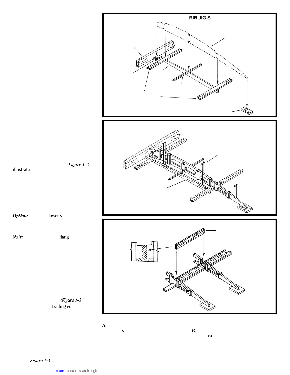
Since the wing ribs have undercamber, jig
shims are required to correctly locate the
beam flanges at their pr
oper angles. The
shims are laser-cut parts.
The leading edge is a r
ectangular spar and is
deeper than necessary so it can sit directly on
the plan without any shim strips. Pin the
leading edge to the plan first. Later, when the
wings are removed from the building board,
the leading edge will be r
ounded to its cor-
rect shape.
Next, lay a 1/32"-thick shim just behind the
leading edge in way of each rib. This will
hold the ribs off the work surface to allow for
the thickness of the cap strips. Also, lay a
1/32"-thick shim under the trailing edge.
Both of the 1/32" shims can be short pieces
in way of each rib or a long strip.
Laser-cut jig shims, W24, are used to hold
the beam flanges at the correct height and
angle. It is suggested that these shims be laid
just to one side of each wing rib rather than
under it, so you can still see the rib locations
on the plan. Pin the shims to the plan. Note
that there are only enough of the laser-cut
parts to build one wing panel at a time. If you
want to build more, you must make your
own additional shims.
Lay down the lower beam flanges and pin
them on top of the jig shims.
Figure 1-2
illustrates the setup. Out near the wing tips,
both of the beam flanges must be tapered as
shown on the plans. Also, the flanges are
angled toward the wing tips outboard of the
last full-size rib. Consequently, you can take
the flanges during this step only out to the
full-size rib and then add the remaining
portion of the flanges when you do the wing
tips (to be discussed later).
Option:
The small lower stringer at the middle of the wing ribs could also be installed
along with the beam flanges. Refer to Paragraph 6 for a discussion on the stringers.
Note:
When pinning the flanges (and the
stringer if the option is chosen) to the shims,
use one of the full-length lightened ribs to
check the fit as you go. The fr
ont end of the
rib will butt against the leading edge, and the
bottom slots in the rib must fit the lower
beam flanges (and stringer).
3. Installing the Wing Ribs
Position and glue each wing rib to the leading
edge, and to the fr
ont and r
ear beam lower
flanges (and the center stringer if this option
is used). Use pins if necessary to hold the ribs
tically at each location
ver
The shor
t ribs at the trailing edge, W7, can
be installed now
, or wait until the trailing
(Figur
e 1-3)
.
edge is in place.
Installing the Beam W
4.
ebs
and Web Blocks
With the ribs in place add the webs at the
ont and r
fr
must be shaped so they ar
bottom of the slots for the upper flanges.
Glue the webs to the lower flanges and to
each rib.
ear beams. The top of the webs
e flush with the
e 1-4
Figur
illustrates the basic
FIG. 1-2 WING RIB JIG SETUP
3/32" X 3/16"
LEADING
EDGE
1/32" SHIM
LOWER BEAM FLANGES
1/32" X 3/32" FRONT
1/32" X 1/8" REAR
JIG W24
1/32" X 1/32" STRINGER
(OPTION – INSTALL NOW)
FIG. 1-3 INSTALLING THE WING RIBS
THIS SHOWS OPTION WITH
W24 OFFSET FROM RIBS
FIG. 1-4 INSTALLING BEAM WEBS
REAR WEB SHOWN
(FRONT SIMILAR)
webs between ribs. Variances are as follows:
A.
The webs between the inboard two ribs
are the same thickness as the flanges.
This thick web suppor
ts the fake hinge
pins that connect the lower wings to the
fuselage and upper wings to the center
section. For the model, drill a hole in the
ends of each web for inserting a fake
hinge made of steel rod. The inboard ribs
8
TYPICAL WING RIB
1/32" SHIM
PINS
BEAM WEB –
1/32" FRONT WEB
3/64" REAR BEAM
5/64" IN WAY OF
AILERONS
already have a laser-cut guide hole (more
on this later).
B.
The rear web outboard where the ailerons
e located is a continuous piece and is set
ar
flush with the aft side of the flange. Like
the flanges, the beam webs outboard of
the last full depth rib ar
e not installed at
this time. They will be done with the wing
tip construction per Paragraph 5.
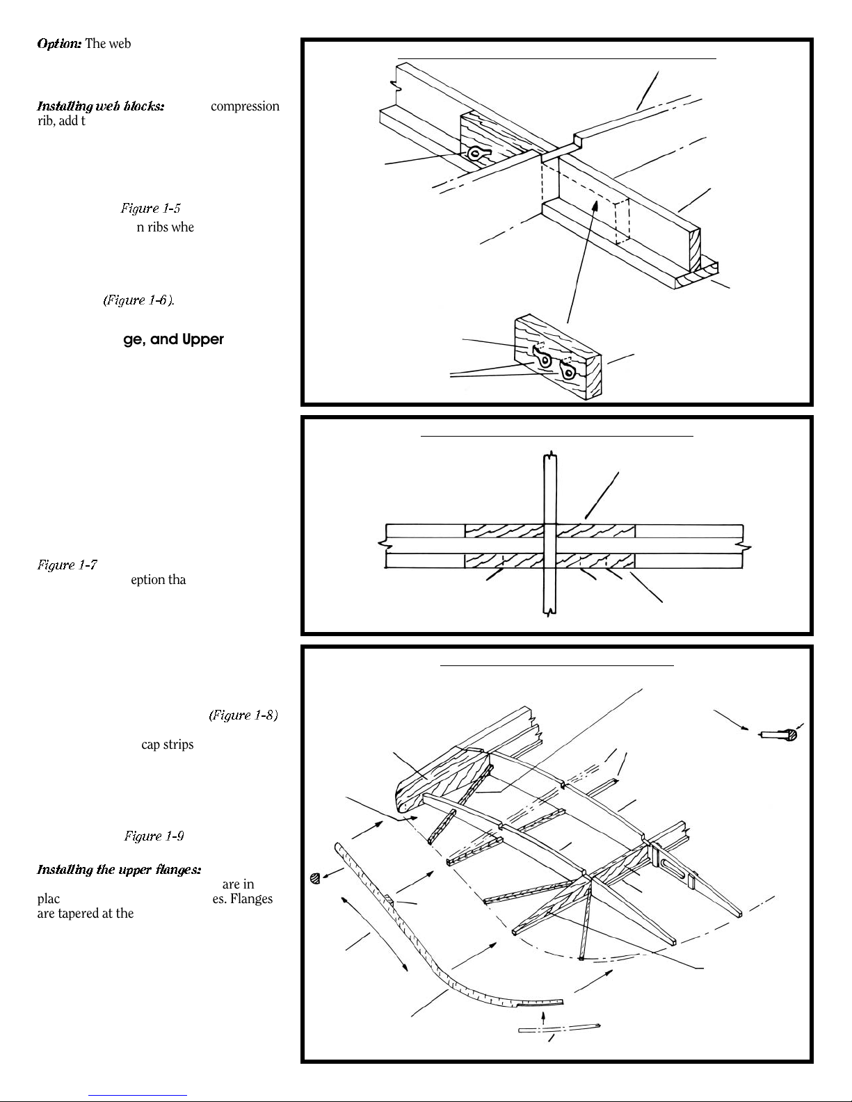
Option:
The web blocks to be described in
the next paragraph can be glued to the beam
webs before the beam webs are glued
between the ribs.
Installing web blocks:
At each compression
rib, add the web blocks on each side of the
ribs. Fit these blocks on the forward side of
the rear beam and aft side of the front beam.
These blocks hold the drag wire single eye rig
fittings (R1). The fittings should be installed
in the blocks befor
now than later.
e installing the block; easier
Figure 1-5
illustrates.
At the compression ribs where the wing
struts are located, add additional blocks on
the other side of the beam webs. The blocks,
now on all four corners of the rib juncture
provide support for the pads in way of the
wing struts
(Figure 1-6).
5. Installing the Wing Tips,
Trailing Edge, and Upper Beam
Flanges
The wing tips are made of wood. The rear
beam flange tapers aft, and its web tapers top
and bottom to the tip. The front beam flange
tapers forward, and its web tapers top and
bottom. See Detail 2-F and 2-G on the plan for
the correct tapers. There is a filler block at the
leading edge. It tapers like the front beam.
Outboard of the last full-size rib there is a narrow wing rib. Taper and fit the wing tips. On
the lower wing, the tip curves into the trailing
edge. Heat bend this curve. Note that the wing
tip follows the curvature of the undercambered wing ribs, so it is not a straight piece.
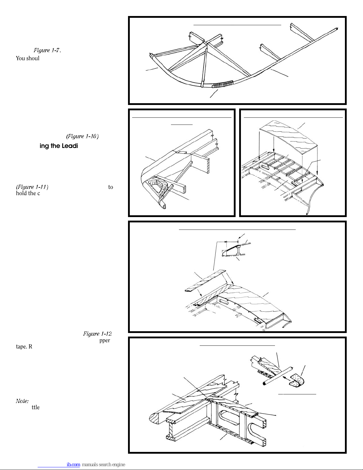
Figure 1-7
illustrates the wing tip construction, with the exception that the upper beam
flanges and stringer have not yet been added.
The trailing edge is a steel rod. It is tied into
the wooden wing tips of the lower wings.
Bend the trailing edge to shape. Splice the
steel trailing edge into the wooden lower
wing tip and wrap with thread. For the upper
wing, the ailerons have the rod. Position and
glue the trailing edge to the ends of the ribs
with just a touch of super glue
(Figure 1-8)
After the wings are removed from the building board, and the cap strips have been
added, the copper self stick bands will be
added at each rib over the trailing edge rod.
The lower wings have a handhold block
(W23). Install the laser-cut blocks and sand
to the taper of the wing tips and round the
hole edges. See
Figure 1-9
and Detail 2-H
on the plan.
Installing the upper flanges:
After all webs
and web blocks and the wing tips are in
place, add the beam upper flanges. Flanges
are tapered at the wing tips. See Detail 2-F
and 2-G on the plan.
6. Installing the Small Wing Stringers
The stringers on the real aircraft are very
small dowels (about 5/16" full-size). However
1/32" square strips are provided in the kit, as
a dowel this small is not available commercially. You can sand the edges of the square
to form a dowel or use a draw plate. Or, leave
the square strips as is for more strength (rec-
.
CURVE SIMILAR
TO CAMBER OF
,
SINGLE DRAG
WIRE FITTING
R1 THIS SIDE
RIGHT WING, REAR BEAM
BLOCKS SHOWN. FRONT
BEAM SIMILAR EXCEPT
SINGLE AND DOUBLE R1
FITTINGS REVERSE SIDES.
(SEE PLAN OF WINGS)
DRILL HOLES FOR R1
FILLER BLOCK
HANDHOLD
BLOCK HERE
(SEE FIG. 1-9)
DOWNWARD
WING RIB W11
1/16" X 3/32" WING TIP
TAPERED AND SHAPED
FIG. 1-5 WEB BLOCKS AT COMPRESSION RIBS
WING RIB W4 OR W6
WEB BLOCK –
DRAG WIRE
FITTINGS R1
FIG. 1-6
WEB BLOCKS AT WING STR
PLAN
1/32" THICK AT FRONT BEAM
3/64" THICK AT REAR BEAM
UTS
ADD WEB BLOCKS ON OPPOSITE
SIDE OF WEBS IN WAY OF WING
STRUT LOCATIONS
WEB BLOCKS
FIG. 1-7 WING TIP CONSTRUCTION
TYPICAL 3/64" X 3/64" STIFFENER.
WING
T
A
STICK TAPE AS SHOWN
STRINGERS
W4
1
W1
WEB
TAPERED
BLOCK
TRAILING EDGE ROD (SEE FIG. 1-8)
FLANGE
(SEE PLAN
DETAILS)
LOWER WING SHOWN
(UPPER WING SIMILAR EXCEPT
FOR CUT OUT FOR AILERONS)
BEAM WEB
PER FIG. 1-5
TIP, USE COPPER
THIS WEB SAME
THICKNESS AND
TAPER AS FLANGES
BEAM LOWER
FLANGE
TAPE
9
ommended). Fit the stringers in the precut
notches in the ribs. Fix with glue. The
stringers are rather delicate, so be careful
handling the strips. Out at the wing tips the
stringers angle towar
seen in
Figure 1-7
d the wing tip strip as
.
You should be able to slide the lower strip
through the notches, or you could lay them
down before installing the ribs (an option
noted in Paragraph 3).
7. Adding Miscellaneous Stiffeners
and Lower Wing Walk
Install the 1/32" square stiffeners between
the ribs adjacent to the inboard edge of the
ailerons.
On the lower wings, fit the supports and
wood sheet over the two inboard ribs, which
provides a wing walk
(Figure 1-10)
.
8. Installing the Leading Edge Cover
Sheet
Install the plywood cover sheet (also plywood veneer on the real aircraft) on top of
the wings only. It fits from the leading edge
strip back to the middle of the front beam
(Figure 1-11)
. Use some small clamps to
hold the cover sheet in position while the
glue dries, or glue the front first, then glue
the sheet to the front beam with super glue
plus accelerator for a quick fix. The wood is
not as long as the upper wing, so you must
have one butt joint. Place the butt joint at
one of the ribs.
9. Installing the Cap Strips
The upper cap strips can be installed while
the wings are still pinned to the building
board. The wings must be removed from the
board to install the lower strips. To hold the
cap strips in position for gluing, use a bent
pin, or super glue the cap strip at the leading
edge and use super glue plus accelerator at
the trailing edge. Then add glue to the
remaining areas. The cap strips butt into the
ply sheet on top of the wing and to the leading edge on the bottom.
After the wings are removed from the building boar
the trailing edge at each rib.
shows the cap strips and also the copper
tape. Remember this figure so you don’t
forget to add the tape later.
Another method for gluing cap strips is to
coat the rib and cap strip with white glue,
let dry, then use an iron to heat-bond the
cap strips on. Though I have no personal
experience with this method, I am told this
works fine.
Note:
are a little thicker than the 1/64"-thick ply
sheet (1/64" basswood not available). Sand
the front of the cap strips flush with the top
of the ply sheet. Also, sand the cap strips at
the trailing edge down to the steel rod before
applying the self-adhesive copper tape. The
ribs are a little deeper at the trailing edge
than is found on the real aircraft.
d, add self-adhesive copper tape over
Figure 1-12
The basswood cap strips at 0.020" thick
FIG. 1-8 WING TRAILING EDGE
LOWER
WING TIP
SPLICE WITH THREAD
FIG. 1-9 LOWER WING HANDHOLD
BLOCK
LEADING EDGE
LASER-CUT BLOCK
W23 – SAND FLUSH
WITH TOP OF WING
AND ROUND
THE HOLE EDGES
FIG. 1-11 LEADING EDGE COVER SHEET
LEADING EDGE SHEET
1/64" PLYWOOD
(UPPER WING SIMILAR)
FIG. 1-12 RIB CAP STRIPS
SAND CAP STRIP FLUSH
WITH COVER PLY
COVER PLY
T
OP
ONL
Y
BUTT LOWER STRIP
O LEADING EDGE
INT
10
1/32"-DIA. STEEL ROD
TRAILING EDGE
(ON UPPER WING, ROD
IS ONL
Y ON AILERONS)
FIG. 1-10 WING WALK – LOWER WINGS
1/64" PLYWOOD
W8
3/64" X 3/64"
STIFFENERS
WING WALK
SUPPOR
W9
CENTER OF BEAM FLANGE
CAP STRIP LATER, OR WING WALK
CAP STRIP
LATER
–
Y
ALK PL
WING W
LOWER WING
SAND CAP STRIP ENDS
DOWN TO TRAILING
BUTT INTO
COVER PLY
EDGE ROD
A
T TRAILING EDGE
.020" X 1/16"
CAP STRIP
ADD SELFADHESIVE
COPPER TAPE
OVER ROD
TS
1
0.Installing Wing Strut, Kingpost,
and W
F
ing Skid Support Pads and
ittings
The support pads are fitted on each side of
the cap strips in way of the struts. For the
lower wing, the inboard pads are on top of
the wing. The outboar
d pads are on both the
top and bottom of the wing. The bottom pads
are supports for the wing skid fittings. On
the upper wing center section, the pads are
located only on the bottom side. On the main
upper wing panels, install the pads on both
sides at the outer wing strut location. The
underside is support for the wing struts, and
the top side provides support for the kingposts. At the inner strut location, locate the
pads only on the underside. The plan, Detail
2-I shows each pad required.
Glue the photo-etched copper wing strut
rigging plates (W22) to the pads, aligning
the center hole on the axis of the rib and
beam. A common photo-etched copper fitting is provided in the kit. However, all the
rigging eyes are not needed at every location. Cut off the eyes not required. The
plan, Detail 2-J, illustrates what each should
look like. Bend the remaining eyes to the
angle of the wing wires.
On the real aircraft, U bolts going under the
beams are used to hold the plates down. On
the model, glue the fitting to the wings. It
will also be held down when you insert the
struts in the holes.
After the fittings have been installed, or
before, drill a hole into the wing through the
center hole of the fitting for receiving the
wing strut, kingpost, and skid end fittings.
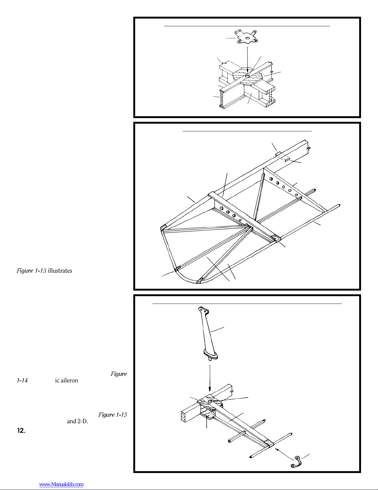
Figure 1-13
illustrates the installation of
pads and fitting.
11. Building and Installing the Upper
Wing Ailerons
Build the ailerons flat on the plan. First, lay
down the leading edge and rod trailing edge,
then pin and glue the ribs to the leading and
trailing edge. Install the stif
fening between
ribs. Add the cap strips as you did the wing
panels, then add the copper bands at each
rib. Cut slots in the ailer
on leading edge and
the rear wing beam web for fake hinges. Use
a strip of brass for the fake hinges. The location of the hinges is fr
om factory plans. However, you could omit all but the two outer
hinges as an option on the model. See
1-14
for the basic ailer
In way of the contr
on construction.
ol horns, add the pads and
Figure
filler blocks on each side of the rib and drill a
hole for the fittings. Install the britannia
casting control horns (C1) and the three
back brace wire fittings (R2). See
Figure 1-15
and plan Details 2-A and 2-D.
12.Installing the Aileron Control
Sheaves
Pin or glue the sheaves (C3) into the sheave
body (C4) to assemble the sheaves. The
sheaves ar
e located on the fr
a U pin made fr
om brass r
ont beam. Inser
od into the beam
to attach the sheaves to the top and bottom
t
FIG. 1-13 STRUT SUPPORT PADS & WING WIRE FITTING
PHOTO-ETCHED FITTING W22 –
BEND EYES TO WING WIRE ANGLES.
CUT
OFF EYES NOT NEEDED
ATA GIVEN LOCATION.
BEAM
CAP STRIP
RIB
DRILL HOLE THROUGH
W22 INT
WEB
BLOCK
O BEAM
TYPICAL FULL .020" SUPPORT
PAD. (SEE PLAN DETAIL 2-I
FOR PARTIAL PADS)
FIG. 1-14 BASIC AILERON CONSTRUCTION
1/64" X 1/16" BRASS FLAT BAR FAKE HINGE
CUT SLOT FOR FAKE
HINGES – CUT MATCHING
SLOT IN REAR WING
W14
AT EACH RIB
COPPER
TAPE
.020" X 1/16"
CAP STRIPS
1/16" X 5/32"
LEADING
EDGE
SELF-ADHESIVE COPPER TAPE
TYPICAL 1/32" STIFFENERS
FIG. 1-15 AILERON CONTROL HORNS & BRACE WIRE FITTINGS
CONTROL HORN CASTING C1
(TOP AND BOTTOM)
.020" PAD
(TOP AND
OM)
BOTT
FILLER BLOCK
DRILL HOLE TOP AND BOTTOM
FOR CONTROL
SOLID RIB
W13
HORNS
PHOT
BACK BRACE
WIRE FITTING R2
11
BEAM WEB
1/32"-DIA. STEEL
ROD TRAILING
EDGE
O-ETCHED
of the wings
C)
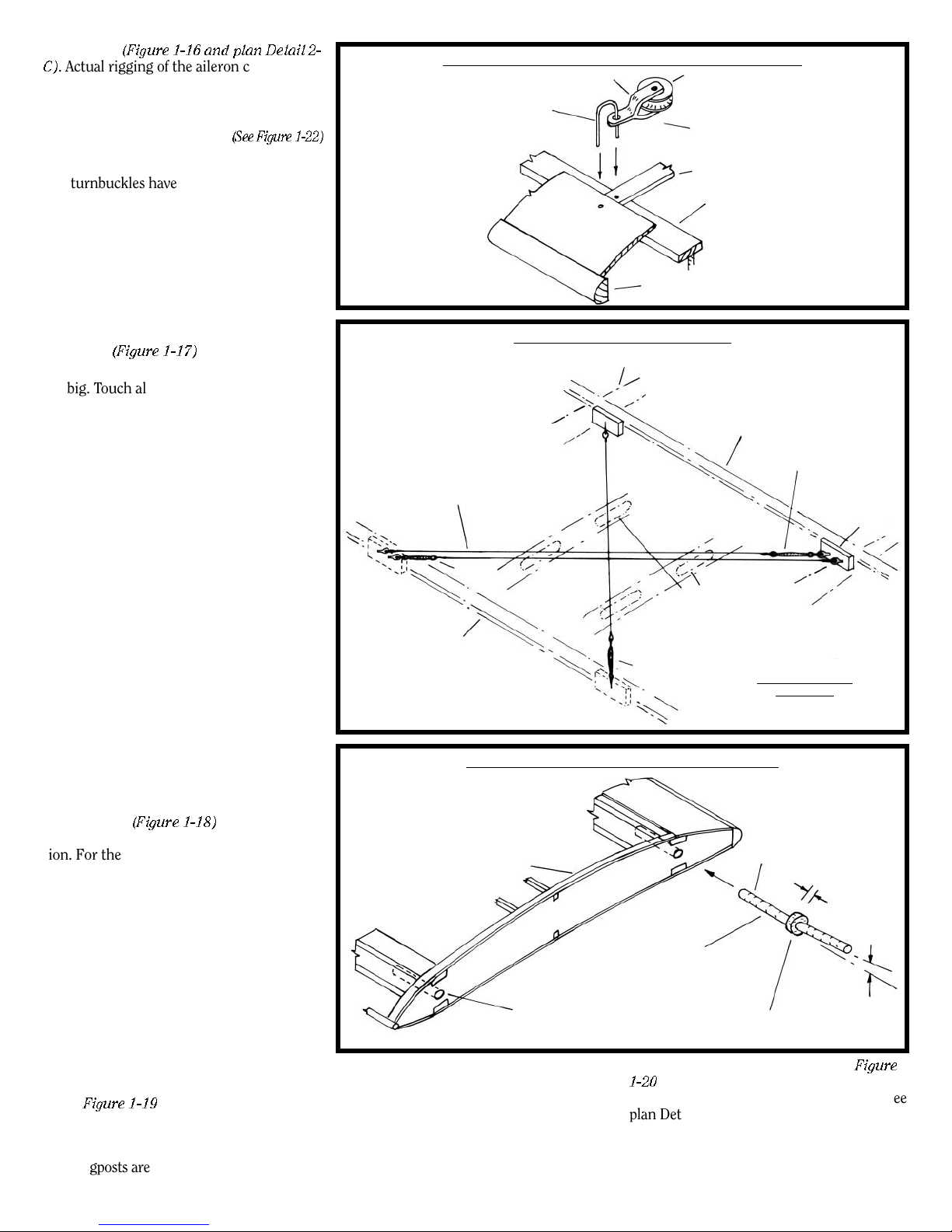
. Actual rigging of the aileron control wires
e 1-16 and plan Detail 2-
(Figur
will be discussed in a later stage.
On the right side of the upper wing center sec-
tion add a similar U pin that will ser
lead for the aileron control wire
ve as a fair-
(See Figure 1-22)
13.Installing the Drag Wires
The turnbuckles have an eye on each end.
One end can be tied with thread to the rig eye
fittings (R1), or if you file out one side of the
eye they can be hooked into the fitting. On
the real aircraft the end is U-shaped for bolting to the fitting.
Add the short turnbuckles (R3A) and rig the
drag wires (nylon cord on the model). These
go between the compression ribs on the main
wing panels and also on the upper wing center section
(Figure 1-17)
.
Try to be neat with the cord. Don’t get knots
too big. Touch all knots with super or white
glue so they won’t come adrift.
14. Installing the Fake Hinge Rods in
the Upper and L
On the real aircraft, the lower wing was attached
to the fuselage and the upper wing was attached
to the center section by a pair of heavy hinges
bolted to the beam webs. Until such time as the
rigging wires were installed, the wings were not
supported and would rotate on the hinge. For
the model, the hinge has been faked to provide
a more rigid connection, so when the wings are
installed they don’t flop around, making installation of the struts and rigging easier. A simple
steel rod is provided as a fake hinge.
First, bend the steel rod to the angle of the wing
dihedral (1°). In order to maintain the 3/32" gap
between the outer wing panels and fuselage/
center wing section, an optional spacer inserted
onto the steel rod is suggested. This can be
made from a piece of wood, or of aluminum or
brass tubing with a 1/16" inside diameter.
Drill a hole in the end of the beams through
ecut guide holes in the inboar
the pr
ting the fake hinge pin. Glue the r
inser
into the holes
hole into the beams of upper wing center sec
tion. For the lower wing, ther
drilled in the fuselage. This will be shown in
the fuselage building stage.
(Figure 1-18)
ower Wings
d ribs for
od
. Drill a similar
-
e will be holes
15. Building and Installing the Lower
ing Skids
W
Using the 3/32" squar
e flexible beech wood,
shape the strip into a 1/16" dowel. The beech
bends rather easily, but can be easier and hold
its shape better if it is wet first. Pin the dowel
over the plan pattern and let dry. It may tend
to flex back a little, but that’s OK. When
installed in the skid fittings, it will be secur
e.
Fit the cast fitting (W21) at each end under
the lower wing, then glue the skids in the
holes.
Figure 1-19
shows the process.
16. Building , Installing, and
Rigging the Kingposts
The kingposts are laser-cut, but you must
taper them and shape to a streamline section.
FIG. 1-16 AILERON CONTROL CABLE SHEAVES
CASTING C4
BRASS ROD
.
FIG. 1-17 WING DRAG WIRES
.010"-DIA. GRAY
NYLON CORD
R3A
FRONT WING
BEAM
FIG. 1-18 INSTALLING FAKE HINGE RODS
WING)
OP
W1 (T
W8 (BOTTOM WING)
DRILL 1/16" HOLE INTO BEAMS
THROUGH PRE-CUT PILOT
HOLES IN LASER-CUT RIB
The end fittings ar
e so small they have been
omitted on the model. Paint the ends black or
copper color to “fake” a fitting that is similar
to the wing str
uts. Install the single eye rig fit
tings (R1) into the posts. Drill a hole in the
bottom of the posts and insert a brass pin.
Insert the kingposts into the holes on top of
the upper wing, then add the steel r
od at top
12
CASTING C3
FITTING AT TOPAND
BOTTOM OF WING
CAP
STRIP
WING FRONT
LEADING EDGE
COMPRESSION RIB
REAR WING BEAM
DRAG WIRES PASS
THROUGH HOLES
IN THESE
LIGHTENED RIBS
R3A
FAKE HINGE
(1/16"-DIA. STEEL
between the fr
Next, add the single eye rig fittings (R1)
1-20
.
ROD)
OPTIONAL SPACER
(WOOD OR
ont and r
BEAM
SHORT TURNBUCKLE
R3A
WEB BLOCK
FITTINGS
TYPICAL
GLUE ROD IN HOLE
PANEL IN
LEFT WING
3/32"
TUBING)
THICK
1 DEGREE
ear posts. See
WITH R1
on the wing for the kingpost brace wires. See
-
plan Detail 2-E.
The rigging for the kingposts can be accom
plished at this time or wait until later
to Stage 7 and Sheet 6 for details. The short
nbuckles (R3A) for the transverse wir
tur
Figur
. Refer
es
e
-
 Loading...