

Model Airways 28, MA1050 Instruction Manual

INSTRUCTION MANUAL
NIEUPORT 28
NIEUPORT 28
NIEUPORT 28
WOORRLLDD
W
FFRREENNCCHH FFIIGGHHTTEERR A
11::1166 SSCCAALLEE
11::1166 SSCCAALLEE
11::1166 SSCCAALLEE
WWiinnggssppaann:: 550088 mmmm ((2200""))
WWiinnggssppaann:: 550088 mmmm ((2200""))
WWiinnggssppaann:: 550088 mmmm ((2200""))
FFuusseellaaggee:: 440000 mmmm ((1155--33//44""))
FFuusseellaaggee:: 440000 mmmm ((1155--33//44""))
FFuusseellaaggee:: 440000 mmmm ((1155--33//44""))
NNoo.. MMAA11005500
NNoo.. MMAA11005500
NNoo.. MMAA11005500
W
ARR II
W
A
AIIRRCCRR
AFFTT -- 11991177
A

INSTRUCTION MANUAL
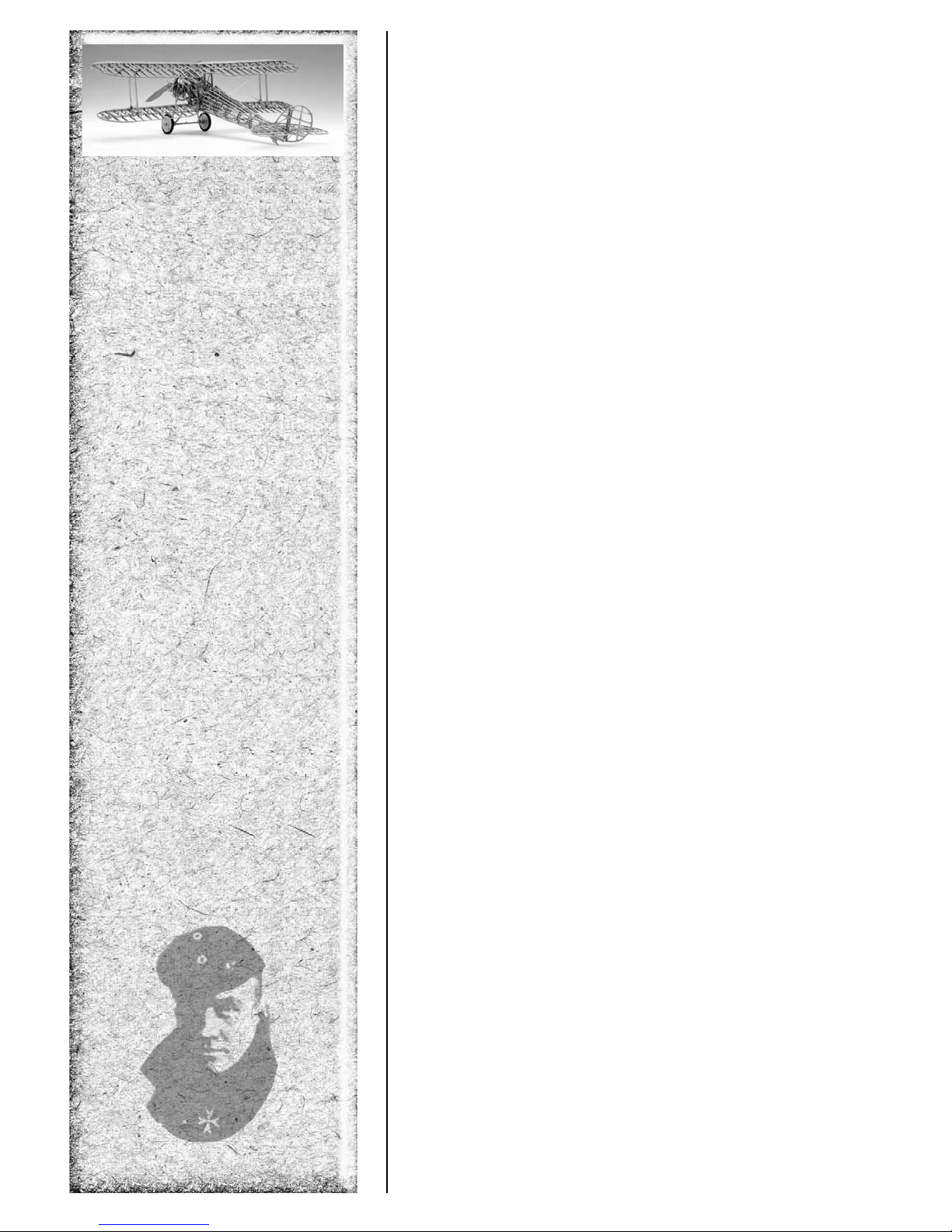
WORLD WAR I FRENCH FIGHTER AIRCRAFT - 1917
NIEUPORT 28
INSTRUCTION MANUAL PREPARED BY KENNETH H. GOLDMAN
SCALE: 3/4” = 1’0” (1:16) • Kit No. MA1050
Wingspan: 508 mm (20 inches)
Fuselage Length: 400 mm (15-3/4 inches)
HISTORY
The French-built NIEUPOR
Nieuport, founded by Edouard de Niéport at Issy-les-Moulinaux in 1910. Many designs were developed including the
first Type 10, then Type 12,17, 24 and 27. The Type 28 was the most streamlined plane and the last of the Nieuport family of single-seater aircraft. First flown in prototype form in June 1917, it was a completely new design, albeit based on
experience gained with the earlier Type 27. Although French-built, the NIEUPORT 28 served in the air services of all the
Allied nations and on all fronts. It was the first fighter aircraft flown in combat by the 27th, 94th, 95th, and 147th
Squadrons of the United States Air Service (American Expeditionary Forces). 297 aircraft were received by the
squadrons. On April 14, 1918, the aircraft’s second armed mission, Lieutenants Alan Winslow, and Douglas Campbell
(the first American-trained ace) of the 94th Aero Squadron both shot down an enemy aircraft. The NIEUPORT 28 was
flown by many American aces, among them the “Ace of Aces” Captain Eddie Rickenbacker, with 26 victories. It was a
favorite because of its speed and maneuverability.
The NIEUPORT 28 has a wingspan of 26 feet 9 inches and has a maximum weight of 1625 pounds (1172 pounds
empty weight). It flies at a speed of 122 mph, has a range of 248 miles, endurance of 1-1/2 hours, and the service ceiling
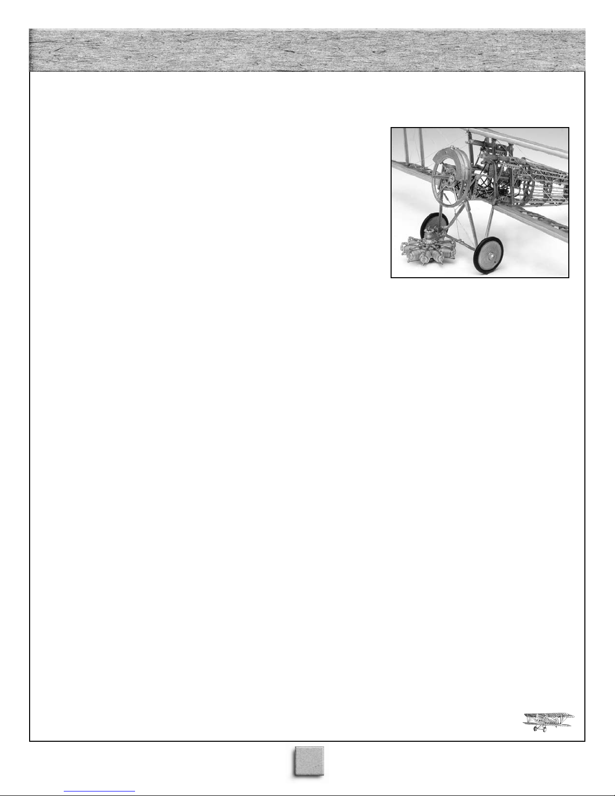
is 17,000 feet. The aircraft is a single-seater and is powered by a 160 HP Gnôme-Rhône Monosoupape 9N, 9 cylinder, air
cooled rotary engine. The plane has no throttle and once started, the Gnome rotary engine runs on full all the time. The
pilot controlled the plane’s speed by turning off and on individual or groups of cylinders. There is no oil pan to re-circulate the castor oil lubrication. After circulating through the engine, the oil simply sprayed out into the air. One can only
imagine the effects on pilots after inhaling a mist of pure castor oil for an hour! Armament consists of two Vickers 0.30
caliber synchronized machine guns.
A number of NIEUPORT 28’s have been restored and can be found in aircraft museums. The Smithsonian Institution’s
Garber Preservation Facility in Suitland, Maryland outside Washington, DC, has recently restored (summer 2000) a
NIEUPORT 28 C-1 for display in the National Air and Space Museum.
T 28 biplane was manufactured by the Nieuport company - Société des Etablissements
INDEX
2
WORLD WAR I FRENCH FIGHTER AIRCRAFT
NIEUPORT 28 - 1917
The NIEUPORT 28 model plans and kit were completed in 2000. The
model was designed for Model Airways by Microfusioni - modellisimo of
Milan, Italy, owned by Luigi Volonté and son Bruno. The designer, Luigi
Volonté, a former World War II fighter pilot, also designed the 1:16 scale
German fighter Albatros D.Va, the first aircraft kit manufactured by Model
Airways. Model plans and original Instructions in Italian were developed by
Luigi Volonté. The text was rewritten in English and expanded by Kenneth H.
Goldman. The model was built by the designer, Luigi Volonté.
Copyright 2000
by Model Airways, Inc., a division of Model Expo, Inc., Hollywood, Florida
Before You Begin
The NIEUPORT 28 kit is intended as a structural, non-flying, model without any fabric covering. It is about as close as you can come to being able to
hold the real thing in your hand. Most every detail of the real aircraft has
been included as model scale permits. Britannia castings and laser-cut wood
fittings eliminate creating many parts from scratch, however, some final finishing is required before they are suitable for the model.
Before starting the model, carefully examine the kit and study the plans.
Every effort has been made to present the construction stages in a clear, logical sequence. Nevertheless, it is recommended that you think several steps
ahead and check the plans accordingly during assembly. This will help clarify
what you are doing now and will ensure proper fit of the sub-assemblies later.
The instructions will help, but a thorough knowledge of the plans at the outset is essential.
Determine if all the listed parts are present. Handling them will produce a
better understanding of the kit’s requirements and will help you visualize how
every piece will look on the completed model. To avoid losing small fittings
and hardware, sort them into labeled containers with lids to keep the parts in
and dirt out.
Although each Stage in the instructions results in a completed sub-assembly, it is recommended that you begin at Stage 1 and proceed in order to the
finish. Certain modeling techniques are described in full when they first
appear in the sequence and only are referred to in subsequent steps. Always
complete one construction stage before moving to the next. If things go awry,
take a break, then consider doing them over.
3

PPllaannss
PPllaannss
The Model Airways’ NIEUPORT 28 kit
is manufactured to a scale of 1:16 or 3/4”
equal to one foot. In addition to the
Figures that appear throughout this
instruction manual, three full-size plan
sheets (D01,D02, D03) are provided.
Each plan sheet is drawn to the actual
size of the model except for some areas
that have been enlarged to better show
detail. Note that full-size Plan D04 (the
propeller) is included in this instruction
booklet.
Dimensions can be lifted directly off
the full-size plans by using draftsman
dividers, a strip of paper laid on the plans
on which you make at dot indicating
each end of a part, or simply by laying
wood strips directly on the plans and
marking where to cut them.
The following table gives inch equivalents and compares full-size dimensions
with scale model inches and millimeters:
Full-Size Inches Scale Inches Scale Millimeters
1/4” 1/64” 0.40mm
1/2” 1/32” 0.79mm
3/4” 3/64” 1.19mm
1” 1/16” 1.59mm
1-1/4” 5/64” 1.98mm
1-1/2” 3/32” 2.38mm
1-3/4” 7/64” 2.78mm
2” 1/8” 3.17mm
2-1/4” 9/64” 3.57mm
2-1/2” 5/32” 3.97mm
2-3/4” 11/64” 4.37mm
3” 3/16” 4.76mm
6” 3/8” 9.53mm
9”
12” 3/4” 19.05mm
A parts list is included in each of the
construction stages, noting the parts
required for that particular stage. A MAS-
ACKAGING P
TER P
rate from these instructions) is provided
that lists the quantities included in the kit.
For wood strips, sheets, rod, wire, tubing,
and rigging, one or several pieces are pro
vided in the kit as noted on the master
packaging parts list. These are identified
both by size and by the names of the air
craft parts that will be made from them.
This material must be cut to length or
shape according to plan dimensions.
9/16”
PPaarrttss
PPaarrttss
AR
14.29mm
TS LIST (sepa-
-
KKiitt LLuummbbeerr
KKiitt LLuummbbeerr
Wood strips and sheets of solid basswood or birch plywood are supplied in
the kit. Generally, these parts will be
referred to by their size as well as their
general part number. Sort and label the
wood in the kit by dimensions to save
time. After selecting and cutting what
you need, return the remaining stock to
the proper thickness and wood type pile.
For best results, cut wood strip lengths a
little long and then sand the ends to
achieve the exact length and fit. Even
though Model Airways supplies enough
extra wood to complete the model before
running out, it is recommended that you
plan to measure and cut the required
parts so as to minimize waste. That way
you are covered if you make a mistake.
CCaasstt--MMeettaall FFiittttiinnggss
CCaasstt--MMeettaall FFiittttiinnggss
These parts will require final finishing
before mounting on the model. Remove
mold joint flash with a #10 or a #11
hobby blade, then file or sand with fine
sandpaper. Some of the holes through
which other parts fit, such as the small
eyes of a turnbuckle, may have filled in
during the casting process. Carefully
clean these out using a drill bit or reamer
and check the fit of the other parts. To
ensure good glue and paint bonds to these
parts, wash off the remaining traces of the
mold release agent. A spray of ammonia
window cleaner and gentle brushing with
an old soft-bristle toothbrush does the job
. Thoroughly rinse the parts and
nicely
allow them to dry.
RRiiggggiinngg LLiinnee
RRiiggggiinngg LLiinnee
On the real aircraft the rigging is 1/8” or
5/32” diameter stranded steel wire. For
the kit, however
single diameter is provided to make it
easier to rig. To reduce or eliminate slackening of the rigging line due to weather
-
changes after you have finished your
model, pre-stretch the line by dampening
it and hanging it with a weight on one end
. I prefer to leave the line hanging
to dry
and cut what I need, as I need it, always
re-attaching the weight.
, metal-gray thread in a
NNeecceessssaarryy
NNeecceessssaarryy
CCoonnssttrruuccttiioonn TToooollss
CCoonnssttrruuccttiioonn TToooollss
The following tools and supplies are
recommended for the construction
process. Modelers who have built before
may have their own favorites.
Knives and saws
A.
1. Hobby knife with No. 11 and No.
10 blades
2. Razor saw or jeweler’s saw
B. Files
Set of needle files
Flat, fine-tooth, mill bastard file
(for fuel tanks)
Round riffler file
C. Clamps and Pins
1. Assorted Bulldog clips
2. Wooden clothespins
(craft shops carry small versions)
3. Rubber bands
4. Package of push-pins or T-pins
D. Boring Tools
1. Set of miniature drills (#60 to #80)
2. Pin vise
E. Miscellaneous
1. Tack hammer
2. Tweezers (a few)
3. Small fine pointed scissors
4. Miniature pliers
a. small round
b. flat nose
5. Wire cutters
6. Mechanics rule graduated in
64ths of an inch and millimeters
F. Sandpaper
#120 aluminum oxide paper for
shaping wood parts
#200 wet/dry silicon carbide paper
for intermediate sanding
#400 wet/dry silicon carbide paper
for fittings and finishing
G. Glue
s glue
White glue or the yellow carpenter
for wood parts. Medium viscosity cyanoacrylate(CA) glue(Super Glue) for metal
parts, metal to wood, and rapid assembly
of wood parts.
3. OPTIONAL
Cyanoacrylate De-Bonder (just in case
you have to take something apart)
Cyanoacrylate Accelerator for an instant
bond. Five-minute epoxy provides extra
strength for gluing fittings.
Water-thin cyanoacrylate glue to bond
fittings by capillary action
’
4
4
H. Building Board
A soft, but stiff board such as acoustic
ceiling tile or insulation wallboard to
easily take straight pins for holding parts
during assembly. This soft board should
be nailed or glued to a hard board so it
will be flat. You can use a table, but a
portable board is good for turning it
around to make the work easier
SSeettttiinngg UUpp
SSeettttiinngg UUpp
TThhee PPllaannss
TThhee PPllaannss
Build the wings, fin and rudder, stabilizer and elevator directly on Plan D02.
Place the plan on your building board
and cover the plan with waxed paper or
plastic wrap. Be careful applying glue,
especially super glue. Although the
waxed paper or plastic wrap protects the
plan somewhat, you could accidentally
glue the protective sheet to the model
parts, or even to the plan itself.
An alternative, if you have a dedicated
modeling area, is to lay a sheet of glass
over the full-size plan sheet and build
directly on the glass, using tape and
weights to hold the parts in position. If
you use this method, watch out for sharp
edges on the glass.
.
board. This will prevent your gluing the
formed part to the work board. The part
will end up glued to the paper, but this easily sands off during the final finishing.
Some people prefer to use waxed paper to
prevent the part’s sticking, but if you use
heat against the jig, you will melt some of
the wax into the laminated part.
Begin by soaking the wood in cold water
for 5 or 10 minutes, then pat it dry
ing at one end of the jig, pin the first strip
tightly against the jig, applying heat when
needed, then move along bending and pinning the wood to shape as you go. Cut off
the excess strip at the end of the run.
Go back to the end where you started and
brush on a thin coat of white glue or carpenter’s glue and apply the second strip of
wood, pulling and replacing pins as you
go. Applying heat at this point will make
an almost instant bond between the wood
strips. Proceed in this manner until you
have built up five wood strips and then
allow the part to dry thoroughly, after
which the formed shape will be permanent.
Carefully remove the part from its jig
and sand off the excess glue and paper.
The final step is to sand the correct profile
as required by the instructions and full-size
plans.
PPaaiinnttiinngg && SSttaaiinniinng
PPaaiinnttiinngg && SSttaaiinniinng
TThhee MMooddeel
TThhee MMooddeel
. Start-
l
l
g
g
When dry, another application of shellac
or your favorite varnish will complete
the process.
Britannia castings parts may be left
polished or painted a steel or gunmetal
color. Other fittings, such as turnbuckles,
can be painted black or dark gray.
arying the tones on the various parts
V
will add a nice contrast to the finished
model.
The distinctive woven plywood “peach
basket” seat back is provided as a
Britannia casting to simplify construction. You will need to paint this, after
gluing it to the seat, to give it an appropriate wood finish. First paint the seat
back with a very light tan. When this is
thoroughly dry, dry-brush a light golden
brown, allowing much of the tan to show
through, then finish off with a russet
brown wash to accentuate the pattern. A
light coat of varnish will then give you
the desired wood effect.
After you have shaped and finish sanded the laminated basswood propeller, you
can achieve a more authentic look by
staining it golden mahogany and then
building up two or three thinned layers
of varnish or shellac.
Sand all wood surfaces with 400-grit
dry sandpaper and thoroughly wipe off
all dust. A tack rag would be helpful.
GGeettttiinngg SSttaarrtteedd
GGeettttiinngg SSttaarrtteedd
Before commencing each stage of construction, have all the parts for that stage
identified and ready to use. It helps to lay
each part on its corresponding location on
the full-size plan to facilitate identification
as you proceed. Lightly sand wood parts as
required to remove any fuzziness and prepare the castings parts as noted above.
To achieve maximum accuracy in your
model you must fabricate bent laminated
parts for wing tips and the empennage.
anganyika
flexibility of the supplied
wood strips - especially when wet - makes
this relatively easy
included in the kit. Because some of the
curves are relatively tight, you may need to
apply heat to the wood as you wrap it
around a jig.
angled tip of a 20-30 watt soldering iron.
Firmly af
a sheet of ordinary typing paper or newspaper sandwiched between the jig and the
This may be done with the
fix each jig, to a work board with
T
The necessary jigs are
.
The
With one exception, your NIEUPORT
28 model need not be painted or finished
at all. However, it is recommended that
you seal the wood parts and Britannia
castings for protection. Due to the intri
cacy of the finished model, this is best
done as you go. My personal preference
is to use 3-pound cut shellac, thinned
50% with denatured alcohol.
fast, so you can keep working, and a second coat can be applied if you want more
shine.
light tan stain on all wooden parts
A
will help to make the entire structure uni
form in color
wood will resist staining, and any end
grain will stain darker than the rest.
achieve an even application of stain,
carefully scrape off any excess glue, then
seal the wood - especially the end grain with thinned shellac.
light application of stain, using a soft
artist’s brush, should give an even finish.
. However
After this is dry
This dries
, glue spots on the
-
o
T
, a
SSttaaggee 11:: BBuuiillddiinng
SSttaaggee 11:: BBuuiillddiinng
tthhee EEnnggiinne
tthhee EEnnggiinne
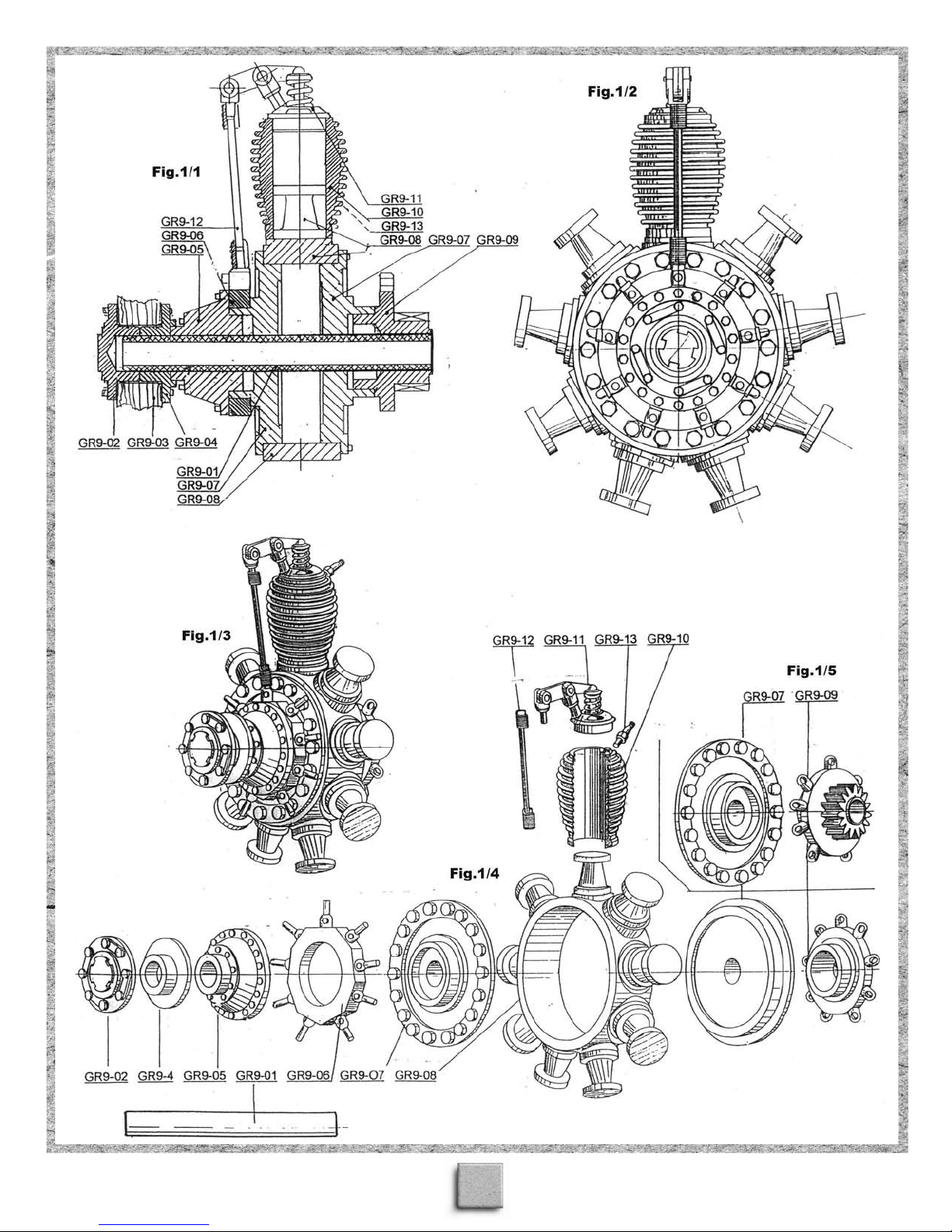
The Gnome-Rhone Monosoupape Type
9N rotary engine is essentially indepen
dent of the rest of the aircraft. It slips
onto a fixed crankshaft around which the
engine rotates. Super glue and/or epoxy
should be used to assemble the parts.
-
Care must be exercised with the many
small parts. Refer to Figures 1/1 through
1/13. For clarity, drawings may show a
single cylinder. It is a simple matter to
repeat the assembly for the other eight
cylinders.
engine is pretty straightforward. The key
to success is to carefully clean up all of
the castings and then to dry fit every
thing before applying glue.
The actual assembly of the
e
e
g
g
-
-
5
5
SSttaaggee 11:: BBuuiillddiinngg tthhee EEnnggiinne
SSttaaggee 11:: BBuuiillddiinngg tthhee EEnnggiinne
PARTS LIST FOR STAGE 1:
GR9-01 Crankshaft mount 1 4mm diameter x 5mm brass tube
GR9-06 Camshaft box 1 Britannia casting
GR9-07 Crankcase covers 2 Britannia castings
GR9-08 Crankcase 1 Britannia casting
GR9-09 Distributor 1 Britannia casting
GR9-02 Front propeller flange 1 Britannia casting
GR9-04 Rear propeller flange 1 Britannia casting
GR9-03 Propeller (laminated) 3 Parts of laser-cut basswood 1/8” thick
J001 Propeller jig 1 1/4” X 20 bolt and nut
GR9-05 Timing gear cover 1 Britannia casting
GR9-10 Cylinders 9 Britannia castings
GR9-11 Cylinder heads 9 Britannia castings
GR9-12 Exhaust valve lifters 9 Britannia castings
GR9-13 Spark plugs 18 Britannia castings
WP—— Ignition wires 9 32-gauge black iron wires
e
e
Crankcase; camshaft box; distributor:
Assemble the engine around the crankshaft mount(GR9-01).
This will ensure that the parts line up properly. Be careful not
to get any glue inside the crankshaft mounting tube.
Begin by attaching the distributor(GR9-09) to the crankshaft
mounting tube(GR9-01) so that the tube end is flush with the
gear side of the distributor. Slip one of the crankcase
covers(GR9-07) onto the tube so that the detail side faces the
distributor and line it up so that the nine rings on the distributor
point between pairs of bolt heads. Next, slip on the
crankcase(GR9-08) and the other crankcase cover. Glue the
crankcase to the rear cover so that the drilled tabs on the distributor will line up between each pair of cylinders(Fig.1/13).
Before you glue on the front crankcase cover, align its bolt
heads to match up with the ones on the rear cover.
Add the camshaft box(GR9-06) on the front of the crankcase,
aligning the pegs dead center on each piston, slide the timing
gear cover(GR9-05) onto the tube and then glue these parts
together. Next, slip the nine cylinders(GR9-10) over the pistons
and glue them in place, paying attention to the orientation of
the spark plug ports. From the pilot’
the outer end of the cylinders, in the plane of the engine, facing
to the right. Glue in the spark plugs(GR9-13).
Attach the cylinder heads(GR9-1
peg on each lines up with its twin on the camshaft box. Make
any needed adjustments to fit the exhaust valve lifters(GR9-12)
between the pegs. Paint, weather
should you wish to do so.
Complete this step by attaching the ignition wires(WP———
-) from the distributor to the spark plugs, referring to Figures
1/11-1/13. Cut nine 55mm lengths of wire. Thread each wire
through one of the nine tabs on the distributor so that equal
lengths emer
itself at the ring, then run one end to each of the spark plugs at
that cylinder and attach as in Figure 1/13. Trim off any excess
wire.
ge from each side. Twist the wire twice around
s point of view
1) to the cylinders so that the
, and highlight the motor
, they are at
,
Propeller group:
Referring to actual-size Plan D04 in the instruction booklet,
laminate the three propeller layers(GR9-03), using the provided
bolt-and-nut jig(J001) to properly align the parts. Once the glue
is dry, remove the bolt and file and sand the propeller to its
refined shape. The front of the laminated propeller is stepped to
guide you in filing the correct shape. The back is then shaped
to follow the front. Begin with the overall lengthwise curve,
then proceed to the cross-sectional shaping. Note that the front
surface is slightly convex and the back surface is concave. Take
your time and check the cross sections on the plan often. When
you are satisfied with the result, apply at one thin coat of varnish or shellac. After the first coat is dry, lightly sand it with
#400 paper to remove any grain raised by the varnish, then
apply a gold-mahogany stain. When dry, follow this with a second coat of varnish or shellac. You can add a third coat of varnish, without sanding first, if that looks better to you.
Paint, if desired, the front(GR9-02) and rear(GR9-04) propeller flanges before fitting them to the propeller. Referring to
Figure 1/7, line up the molded-on front and rear bolt heads/nuts
before gluing the flanges to the propeller
onto the crankshaft mount. If necessary, file the end of the
brass tube so that the propeller assembly snugs up to the timing
gear cover
, then, glue it in place.
. Dry fit this assembly
6
6
7
7
8
8
9
9

SSttaaggee 22:: BBuuiillddiinngg tthhee UUppppeerr W
SSttaaggee 22:: BBuuiillddiinngg tthhee UUppppeerr W
The upper wing is built in two separate sections that will be joined later at the aircraft’s center line. Refer to Figures 2/1 through 2/15 for the number and location of
the parts. Ribs are numbered out from the centerline. The following procedures will
need to be repeated for the right and left upper wings.
Wiinngg
Wiinngg
PARTS LIST FOR STAGE 2:
Ni28-001 Ribs #1 4 laser-cut wood parts 3/64 thick
Ni28-002 Ribs #2 2 laser-cut wood parts 3/64 thick
Ni28-003 Ribs #3-10, 12 18 laser-cut wood parts 3/64 thick
Ni28-004 Ribs #11 2 laser-cut wood parts 3/64 thick
Ni28-005 Ribs #13 2 laser-cut wood parts 3/64 thick
Ni28-006 Ribs #14 2 laser-cut wood parts 3/64 thick
Ni28-007
Ni28-008
Ni28-009 False ribs #B 2 laser-cut wood parts 3/64thick
Ni28-017
Ni28-018 Compression bar 4 Britannia metal
Ni28-020 Joint pin plates 4 Britannia metal
WP3688-24 Rib caps .02 x 5/64 wood strips
WP3688-24 Leading edge cover 7 .02 x 5/64 wood strips
WP3631-24 Front and rear spars 4 1/8 x 1/8 wood strips
WP3640-24 Leading edge 2 3/16 x 3/16 wood strips
WP3620-24 Trailing edge 2 1/16 x 1/8 wood strips
WP3202-40 Wing tips (laminated) 5 .02 x 5/32 Tanganyika wood strips
WP3202-40 Center trailing edge
WP5101-24 Joint pins 2 1/8 x 1/4 wood dowels
W042 Turnbuckles 28 Britannia castings
WP1205 Rigging cable 7” Metal-gray thread
J002 R-L Upper wing tips jigs 2 laser-cut wood parts 5/32 thick
J003 Upper center
Wing ribs; cap strips:
Begin by laminating two parts Ni28-001 to form each Rib #1. Take the required
lengths of the rib cap strips(WP3688-24) from full-size Plan D02. (Note that the rib
cross sectional drawings are double size and reduce your measurements accordingly if
you refer to these.) The rib cap strip edges will be flush with the sides of laminated
ribs #1, but they must overlap the other ribs equally to each side. The easiest way to
accomplish this is to pin each rib on its side, through the lightening holes, then slip a
couple of pieces of .02î thickness wood strip between the rib and the assembly board.
This will automatically set the required overlap when you glue on the cap strips. Hold
the cap strips in place with pins while the glue dries.
Inserting the spars; leading edges; trailing edges:
Using full-size Plan D02, cut the front and rear spars(WP3631-24) to the required
lengths. Carefully taper them from where they pass through rib #12 out toward the
wing tip where the cross section should be reduced to 5/64 x 5/64. This should be done
evenly from all four sides.
Next, adjust the spar holes in the ribs so the spars slip through without binding. Pin
the assembly down, making sure everything is square, and glue the spars in place.
Finally, cut the leading(WP3640-24) and trailing(WP3620-24) edges to size and glue
them in place against the ribs.
After the glue dries thoroughly, unpin the structure. Using a long strip of sandpaper,
Ribs #15 2 laser-cut wood parts 3/64 thick
False ribs #A 2 laser-cut wood parts 3/64 thick
Nose ribs 30 laser-cut wood parts 3/64 thick
(laminated) 5 .02 x 5/32 Tanganyika wood strips
trailing edge jig 1 laser
-cut wood part 5/32 thick
about 11”, affixed to the same length
straight piece of wood, sand the leading
and trailing edges to the correct cross section. This technique will ensure a uniform
shape.
Wing tips and center trailing edges;
false ribs:
Here is where you will likely be expand
ing your skills, actually making shaped
plywood by bending and gluing wood
strips around a form. The procedure is the
same for all four parts. Secure jigs J002
and J003 to a paper covered board.
Referring to Plan D02 and Figures 2/7 and
2/8, cut five lengths of Tanganyika wood
strips(WP3202-40) for each wing tip.
Bend and glue the strips as described
above, pinning the sandwich against a jig
to establish the correct shape as the glue
dries.
Remove the wing tips and center trailing
edges from the jigs and shape them as
necessary for installation on the wings.
Note that Plan D02 shows mitered, not
butt, joints where the wing tips are glued
in place. This provides greater strength to
the glue joint. Glue the false ribs(Ni28008, Ni28-009) in place.
Nose ribs; leading edge cover:
Using Plan D02 as a guide, glue the
nose ribs(Ni28-017) in place. After the
glue is dry, a light sanding, if needed, with
the sanding paddle will ensure both ribs
and nose ribs perfectly line up on the
upper wing surface.
Glue the eight strips of the leading edge
cover(WP3688-24) in place, proceeding
from the leading edge toward the forward
spar. After the glue is dry, sand the ends to
conform to the wing’
cover to a smooth surface. [The kit sim
plifies the rear edge of the leading edge
cover by leaving it straight across. In the
actual aircraft, this was shaped into a for
ward, flattened arc between each pair of
ribs, for an overall scalloped effect. If the
advanced modeler wants to make this
modification, be careful that the arcs have
a uniform amplitude.]
Compression bars; rigging:
Referring to Figure 2/10 and Plan D02,
use a bent pin, working in from both
sides, to carefully bore 0.5mm(.020î)
holes through ribs #1, 4, 6, 8, 13 and 15
for the rigging(WP1205) to pass through
against the spars.
Precisely align the compression
bars(Ni28-018) and glue them in place.
s shape and sand the
-
-
-
10
10
 Loading...