

Modcan Dual Delay Manual
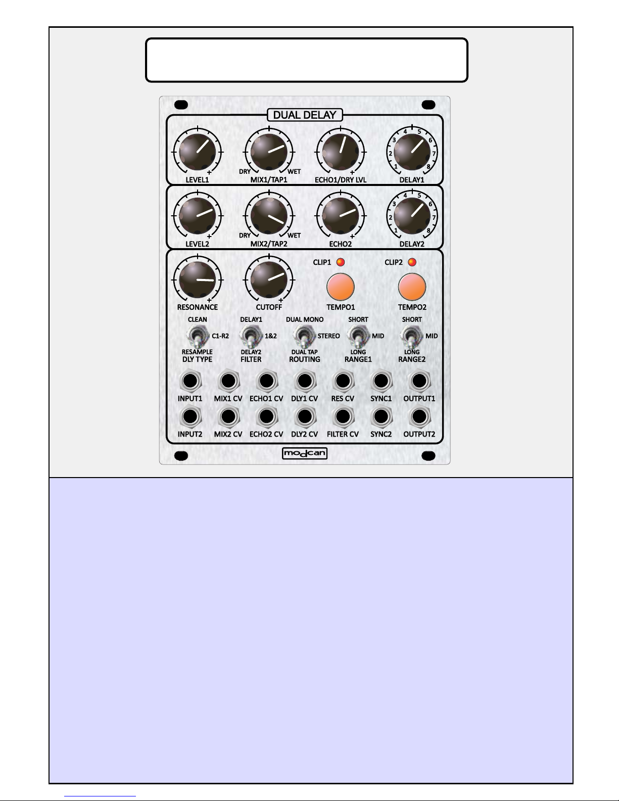
Module Functions:
Each of the two delay channels has both independent and shared controls. The Level, Mix,
Echo, Delay time and Tap are independent while the filter and switches are common.
Panel Controls:
LEVEL: The Level controls set the input level to the module. These are simple attenuators
adjustable to prevent input levels from clipping which could cause distortion or harshness to
the sound. Clipping is indicated by the RED clip LEDs. The Echo amount and filter will also
influence the internal level within the delay and can cause clipping. Adjust the input level
accordingly to control overloading. The LEDS are Bi-Color. Red for clipping and Green for
sync or tap timing indication.
MIX: The mix controls set the wet (delayed signal) and dry (input signal) mix input. With
these knobs set at mid point the mix is 50/50. There is also a CV control for mix that is
summed with the panel knob. CV inputs are all designed to accept up to +/-5V.
The mix controls also do double duty as delay level in Dual Tap mode. (See Routing switch)
ECHO: The Echo sets the depth of regeneration or feedback for each delay channel.
High levels of feedback can introduce clipping which can be reduced with the channel input
Levels knobs.
pg.1
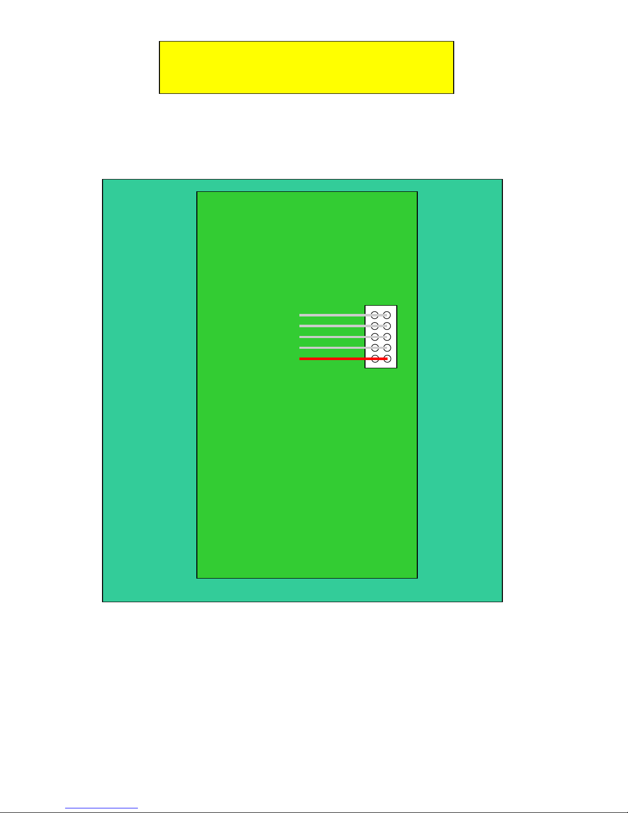
***IMPORTANT***
Top edge
+12V
}
GROUND
-12V
Rear Board View of module
Place RED wire of ribbon cable
so that it is connected to pins shown above
pg.2

Panel Controls Continued:
DELAY: The Delay knobs 1 and 2 set the delay time duration in conjunction with the RANGE
switch selector. The delay times are different for the CLEAN and RESAMPLE delay modes
as selected by the DLY TYPE switch (see below). The DELAY knobs also set the division
for SYNC between 1-8 divisions of the clock patched to the SYNC input jacks.
See Range switch page 4 for more info about delay duration.
RESONANCE and CUTOFF: The Cutoff control sets the frequency of the internal 24dB
Lowpass filter that is situated in the feedback path of each delay channel. The filter is
common to both delay channels but can be routed to each channel separately or applied to
both simultaneously assigned by the FILTER routing switch (see below). The resonance
controls the feedback of the filter (not the delay feedback).
The filter helps to emulate analogue type delay effects such as Bucket Brigade or Tape delay
effects by reducing the bandwidth of the wet signal typical of these type of FX. BBDs
especially suffer from reduced bandwidth at longer delay times.
SWITCH FUNCTIONS:
DELAY TYPE: The Delay Type switch selects between the two types of delay available.
The CLEAN mode sets the channels to typical Digital Delay sound with no pitch shifting
during changes to delay time either with the Delay knob or CV.
The RESAMPLE mode produces pitch shifting effects when delay time is modulated or
adjusted with the Delay pot. This Mode is included for users interested in emulating
Analogue Delay effects and is particularly well suited for modulated delays or emulations of
tape speed fluctuations etc. With the switch in CLEAN position both channels are clean. In
the centre position C1-R2, channel 1 is clean and channel 2 is resample mode.
In RESAMPLE position both channels are in resample delay mode.
See page 6 for diagram showing the structure of each delay type
FILTER SWITCH: There are two filters internally but only one set of controls for both so
frequency and resonance is the same for both channels. The FILTER switch controls the
routing of the filter between the two channels. In DELAY1 position the filter is only applied to
channel one. Channel two is not filtered. In the 1&2 position both channels are filtered.
In DELAY2 position only channel 2 is filtered.
ROUTING SWITCH: The routing switch is used to route the signal path between the input
jacks and delay channels. In DUAL MONO position Input jack 1 is routed to channel one
delay and outputs at OUTPUT1. This applies also to Input2 which is routed to Delay channel
2 to provide two channels of independent monophonic delay with separate control over delay
time, echo amount , mix etc. In STEREO position Input one is routed to both delay channels
and output on OUTPUT1 and OUTPUT2 for stereo delay with independent control of delay
time, echo amount and mix for each channel. INPUT2 is summed with INPUT1 to make it
possible to mix two signals before routing to the delays.
With the switch in DUAL TAP position INPUT1 and 2 are summed and routed first to Delay
channel one and then to Delay channel 2 in series. This allows for “delay within delay” effect
or pseudo multi-tap delay effect. The knobs assume a different roll in this mode with Mix1
and Mix2 controlling the level of each delays “wet” amount while ECHO1 controls the level of
the DRY signal to the overall mix. ECHO2 becomes the master echo amount for both delays.
Output 2 is the MAIN output in this mode. Output 1 is from delay channel 1 without any
DRY mix and can be used for dual output stereo field effects when panned left or right with
channel 2 on the opposite side.
See Routing Modes on page 7 of this manual for more info.
pg.3

Switches Continued:
RANGE SWITCH: In order to make the available delay timing more precise it is divided into
ranges. The Range switches set the range available to the delay knobs in conjunction with
the Delay CV inputs using the following values. Note that Resample and Clean have different
ranges.
Resample Delay Ranges
SHORT: 0.01s - 0.06s
MID: 0.06s - 0.5s
LONG: 0.5s - 4s
Clean Delay Ranges
SHORT: 0.0006 - 0.02s
MID: 0.02s - 0.91s
LONG: 0.91s - 5.46s
The sync and tap tempo feature overrides these ranges and instead derives the delay time
by measuring the duration between pulses at the SYNC jack inputs or taps from the TAP
TEMPO buttons.
TAP TEMPO: The Tap Tempo buttons as mentioned above are used to set the delay time
based on tap timing. This is a handy feature for aligning delay tempo with live or recorded
music. There are TAP buttons for each channel of delay. The CLIP LED will blink GREEN
to indicate the tempo of taps. To resume manual delay timing control rotate the DELAY1 or 2
knobs to switch off the tap function. The SYNC division function is not used in tap mode.
SYNC JACKS: The SYNC function is enabled when a pulse or clock from an LFO etc. is
patched to the sync jacks. The timing of the pulse is calculated and applied to the delay time
and the Delay knobs then function as controls for setting the a division value between 1 and
8. For the delay time to be equal to the clock or pulse time set the division
to 1. To disable this function and return to manual control of delay time, remove the clock
from the sync jack, TAP once on the tap tempo button and turn the delay control knob of the
same channel. The green LEDs will stop blinking, indicating sync is off.
pg.4

The above diagram shows how to connect the module if external feedback is required.
Putting a Frequency shifter or other processing module in the feedback path makes for interesting
results.
pg.5

Clean Delay core (1 channel)
Feedback
In
In Out
+ Buffer Filter
Delay
Resample Delay core (1 channel)
Feedback
+ Buffer Filter
Downsample Upsample
Out
Rate
Delay
pg.6

Dual Mono Mode
Wet/Dry 1
In 1
In 2
Delay Core 1
Out 1In 1
Wet/Dry 2
Delay Core 2
Out 2In 2
Stereo Mode
Wet/Dry 1
Delay Core 1
+
Wet/Dry 2
Delay Core 2
Out 1
Out 2
Dual Tap Mode
I n 1
+
+
I n 2
F e e d b a c k 2
Note: In this mode the Wet/Dry controls are re-purposed as levels for each of the delay
outputs. ECHO 1 becomes the dry signal level control and ECHO 2 sets the depth
of feedback for the summed delays.
+
D e l a y C o r e 1
( I n t e r n a l f e e d b a c k
I s d I s a b l e d )
D e l a y C o r e 2
( I n t e r n a l f e e d b a c k
I s d I s a b l e d )
pg.7
F e e d b a c k 1
W e t / D r y 1
W e t / D r y 2
+
Output 1 is Delay 1 out
with no dry mix for Dual
Tap mode
O u t 1
+
Output 2 is main out
for Dual Tap mode
O u t 2
 Loading...