

Modas mc1, mc4, mc2 User Manual

MC
802.11 a/b/g/n
Wireless LAN-Bridge
&
Serial Client Adapter
Manual
MC Manual Version 2.10c
1

Table of Contents
1 Technical Description..................................................................................................................................... 4
1.1 Ports of the MC1..................................................................................................................................... 5
1.2 Ports of the MC2..................................................................................................................................... 6
1.3 Ports of the MC4..................................................................................................................................... 7
1.4 Meaning of the LEDs............................................................................................................................... 7
1.5 Technical Properties................................................................................................................................ 8
1.6 Wireless LAN - Interface......................................................................................................................... 9
2 Initial startup.................................................................................................................................................. 9
2.1 The MC-Config-Application..................................................................................................................... 9
2.2 Reset to factory settings........................................................................................................................ 12
3 Setup of the parameters via Web-Interface................................................................................................. 13
3.1 General Information............................................................................................................................... 13
3.1.1 System Information......................................................................................................................... 13
3.1.2 Wireless Status Information............................................................................................................ 15
3.1.3 Wired LAN Status Information........................................................................................................ 16
3.1.4 Serial1............................................................................................................................................ 16
3.1.5 Relay Status Information (Optional)................................................................................................ 17
3.1.6 Network Information........................................................................................................................ 17
3.1.7 Access point information................................................................................................................. 18
3.2 Device Menu......................................................................................................................................... 19
3.2.1 Firmware......................................................................................................................................... 19
3.2.2 Configuration Management............................................................................................................. 19
3.2.3 Configuration.................................................................................................................................. 20
3.2.4 Statistics......................................................................................................................................... 20
3.2.4.1 Statistics - System Log........................................................................................................ 20
3.2.4.2 Statistics - Network.............................................................................................................. 21
4 Bridge Modes............................................................................................................................................... 21
4.1 LAN Client Cloning................................................................................................................................ 22
4.1.1 Parameter for the “LAN Client Cloning mode”................................................................................ 22
4.1.2 NAT- und Single Client NAT Mode................................................................................................. 23
4.1.2.1 Advantages:......................................................................................................................... 24
Disadvantages:................................................................................................................................ 25
4.2 Level 2 Bridge Mode............................................................................................................................. 25
4.3 MWLC-Mode......................................................................................................................................... 25
5 WLAN interface parameter.......................................................................................................................... 28
5.1 Wireless LAN Parameter....................................................................................................................... 28
5.2 Wireless SSID Profile............................................................................................................................ 29
5.2.1 SSID Profile.................................................................................................................................... 29
5.2.2 Profile change action...................................................................................................................... 29
5.2.3 Security Parameter......................................................................................................................... 29
5.2.4 EAP................................................................................................................................................ 30
5.2.5 Certificates...................................................................................................................................... 31
5.3 Wireless Roaming................................................................................................................................. 31
5.3.1 Roaming Parameter........................................................................................................................ 31
5.3.2 Ping-Test........................................................................................................................................ 32
5.3.3 Access Point List............................................................................................................................ 33
6 Debug.......................................................................................................................................................... 34
6.1 Recording system messages................................................................................................................ 34
6.1.1 Setting the debug file destination.................................................................................................... 34
6.1.2 Specifying additional information for the debug messages.............................................................34
6.1.3 Debug Configurations..................................................................................................................... 35
6.2 Recording of data traffic from the LAN or WLAN interface....................................................................37
6.2.1 Download the debug files with the MC-Config program..................................................................38
7 Function of the serial interface..................................................................................................................... 40
7.1 Parameters of the serial interface.......................................................................................................... 40
7.1.1 Section Network-Configuration....................................................................................................... 41
7.1.2 Section "Keep alive" settings.......................................................................................................... 41
7.1.3 Section „Handshake-Mode“............................................................................................................ 41
8 Configuration of MC devices with an USB memory stick............................................................................. 42
8.1 Application for the Config-USB-Stick..................................................................................................... 42
8.2 Initializing a USB memory stick............................................................................................................. 42
MC Manual Version 2.10c
2

Table of Figures
Figure 1: Overall System (example)................................................................................................................. 4
Figure 2: Ports and LED's of the MC1-SL-M12................................................................................................. 5
Figure 3: WK8 power connector (with relay + digital input)............................................................................... 6
Figure 4: M8 power connector + extra M8 connector with relay + digital input................................................. 6
Figure 5: MC2 plug assembly on the back panel.............................................................................................. 6
Figure 6: MC4 plug assembly on the back panel.............................................................................................. 7
Figure 7: Setting for the initial configure of the MC........................................................................................... 9
Figure 8: Screenshot of the MC-Config-Application........................................................................................ 11
Figure 9: Access point list.............................................................................................................................. 18
Figure 10: Configuration Management............................................................................................................ 20
Figure 11: Example of a system log message................................................................................................ 21
Figure 12: Example output of Statistics Network............................................................................................21
Figure 13: LAN Client Cloning Mode.............................................................................................................. 23
Figure 14: NAT-Modus (Beispielkonfiguration)............................................................................................... 24
Figure 15: Screenshot NAT-Rules.................................................................................................................. 24
Figure 16: Level 2 Bridge Beispielkonfiguration.............................................................................................. 25
Figure 17: MWLC-Mode example setting........................................................................................................26
Figure 18: Parameter for the MWLC-Mode..................................................................................................... 26
Figure 19: Parameter for the MWLC-Mode..................................................................................................... 27
Figure 20: Parameter for the Pingtest function............................................................................................... 33
Figure 21: Preferred or avoided AP list.......................................................................................................... 33
Figure 22: Debug Log Parameter................................................................................................................... 35
Figure 23: Debug Configurations.................................................................................................................... 37
Figure 24: Traffic Dump Configuration............................................................................................................ 37
Figure 25: Wireless and Ethernet Dump file list.............................................................................................. 38
Figure 26: Download Dumps and Logs.......................................................................................................... 39
Figure 27: file selection to download or delete............................................................................................... 39
Figure 28: Init USB Config Stick.................................................................................................................... 42
MC Manual Version 2.10c
3

1 Technical Description
The MC is a Wireless LAN-Adapter that connects devices via Ethernet, USB or serial Port to wireless
networks conforming to the 802.11a/b/g/n standard.
The MC can connect via these interfaces:
1. 1, 2 or 4 Port LAN
2. serial RS232 , 422, 485 interface
3. USB2 port
The central component of the MC is a ARM® Cortex®-A9 Processor which controls all functionality.
The different ports are:
1) Mini-PCI-Express Socket
2) Ethernet-Interface with 1-4 Ports 10/100/1000 Mbit/s + Auto-MDIX (auto crossover function)
3) 1 x serial Port with six control lines (RTS, CTS, DTR, DSR, DCD, RI)
4) 1 x USB2 – Port e.g. for printers or port extensions
5) optional: relay switching contact + input with opto coupler
MC Manual Version 2.10c
Figure 1: Overall System (example)
4
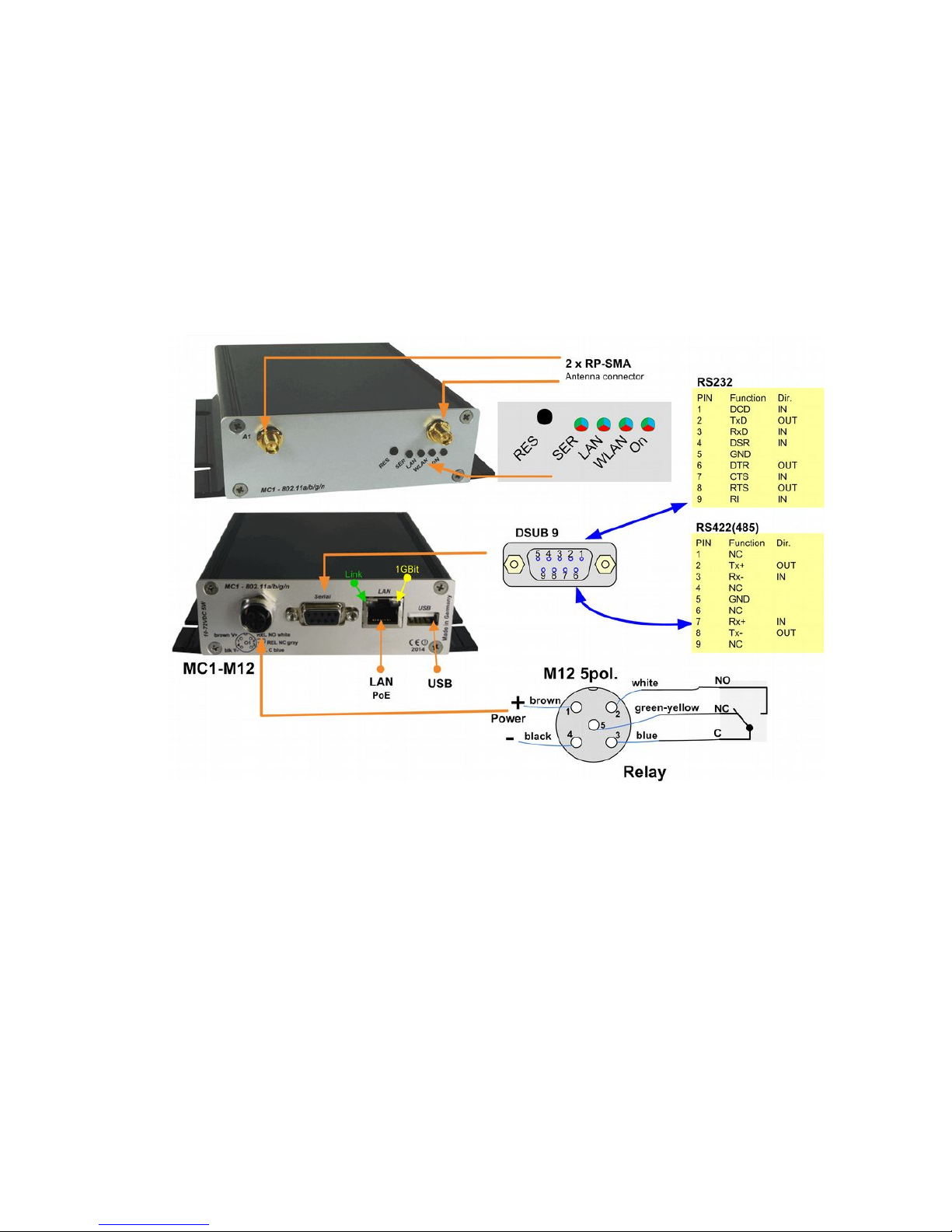
The Ethernet connection is connected via an RJ45 connector. LAN port 1 has a PoE function (IEEE 802.3af)
so that the MC can be powered by this port.
The serial port is connected by a 9pin D-SUB plug. The assignment is selected in a way that a 1:1 serial
cable can be used for the connection to a serial COM-Port of a PC. The exact assignment can be seen in
Figure 2.
The power supply for the MC device needs a voltage source of 10-72V. The usual power consumption is
around 3-4 Watt (WLAN + LAN-Port active).
1.1 Ports of the MC1
The following figures show how the LEDs and ports of the MC are arranged.
Figure 2 shows the MC1 in its standard design with one serial Port, a 5pin M12 connector for power supply
and a relay switching contact.
There are different option for the power connector of the MC devices:
MC Manual Version 2.10c
Figure 2: Ports and LED's of the MC1-SL-M12
5
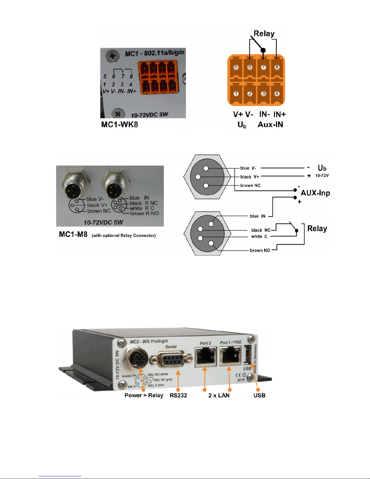
1.2 Ports of the MC2
The front panel of the MC2 is identical to the MC1.
The MC2 back panel has the following plug assembly:
The MC2 is also available with the options MC2-Sx-WK8 and MC2-Sx-M8.
MC Manual Version 2.10c
6
Figure 3: WK8 power connector (with relay + digital input)
Figure 4: M8 power connector + extra M8 connector with relay + digital input
Figure 5: MC2 plug assembly on the back panel
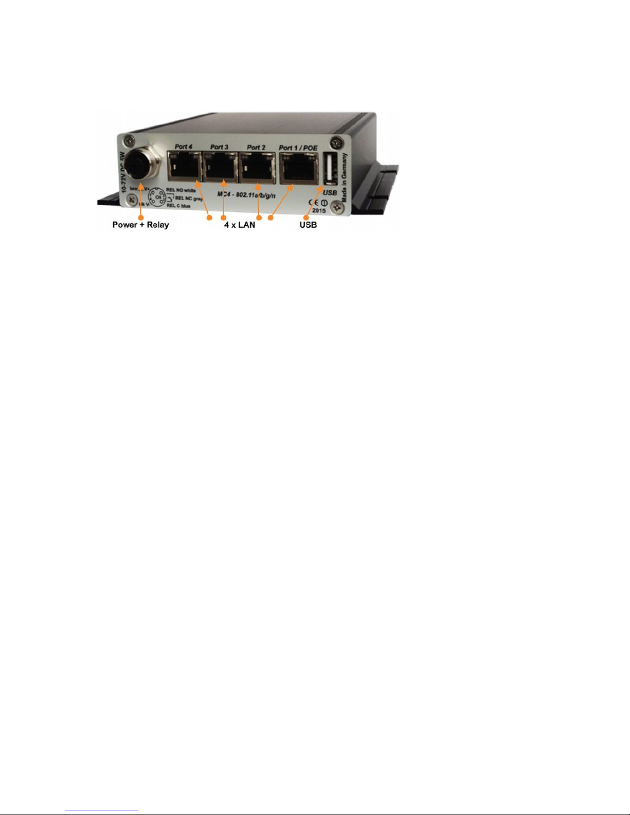
1.3 Ports of the MC4
The front panel of the MC2 is identical to the MC1.
The MC4 back panel has the following plug assembly:
MC4 plug assembly on the back panel
The MC4 is also available with the options MC4-Sx-WK8 and MC4-Sx-M8.
1.4 Meaning of the LEDs
The 4 LEDs on the front represent the operating state of the MC. All LEDs can shine in three different colors:
red, yellow, blue. If all three colors are on, the LEDs color is white.
MC Manual Version 2.10c
7
Figure 6: MC4 plug assembly on the back panel

LED State Mode
On Off No or not enough power
Green Sufficient voltage connected
Green + blinking
orange (red & green)
Standard mode
MC ready
WLAN Off WLAN option off
Blinking red MC is looking for suitable APs or is
currently authenticating
Green Wireless LAN connection works.
Short orange blinking shows activity
(sending or receiving of data) at the
interface.
LAN
Off No device connected to the LAN-Port
Green Device connected to LAN-Port.
Short orange blinking shows activity
(sending or receiving of data) at the
interface.
Serial Off The interface is inactive.
Green A partner-device is connected to the
interface. Short orange blinking shows
activity (sending or receiving of data) at
the interface.
Blinking green The interface is ready and awaits a
connection.
Table 1: LED-Modes
1.5 Technical Properties
Specifications:
Ethernet 1, 2 or 4 x 10/100/1000 MBit Auto MDI/MDIX
Serial 1 x RS232, 300-460,8 KBit/s, RTS, CTS, DSR, DTR, RI, DCD
or (optional) RS485
USB 1 x USB 2.0
Relay 1 x Switch over, max 1A@24V, max 125VAC
Signal Input 1 x galv. separated 10 – 72V
Antenna Connectors 2 x RPSMA (optional TNC or RPTNC)
Power Supply 10 – 72VDC or 802.3af PoE via LAN Port1
Energy <= 5W (typically 3W)
Temperature 0-60°
MC Manual Version 2.10c
8
Dimensions 105x125x35mm
Weight ca. 400g
1.6 Wireless LAN - Interface
Wireless LAN-Interface:
Technology 802.11 a/b/g/n WLAN (2.4 + 5 GHz Band)
Antennas 2 Antennas (2T2R MIMO)
Encryption WEP (64,128bit) + TKIP/AES
Security 802.11i WPA(2) – PSK
802.1x EAP-PEAP, -TLS, -TTLS, -LEAP
Channels 802.11b/g/n ETSI 1-13, USA/Canada 1-11
802.11a/n ETSI 19, USA/Canada 25 (U-NII-1 + UNII-2A + U-NII-2C+U-NII-3)
Data Rates Mode Data Rate
802.11b: 1, 2, 5.5 , 11Mbps
802.11g / a 6, 9, 12, 18, 24, 36, 48, 54Mbps
802.11n (20MHz) 1Nss: max. 72.2Mbps
2Nss: max. 144.4Mbps
802.11n (40MHz) 1Nss: max. 150Mbps
2Nss: max. 300Mbps
Transmission Power 802.11b/g 17 dBm
802.11gn 16 dBm
802.11a 15 dBm
802.11an 15 dBm
Table 2: Properties of the Wireless LAN-Interface
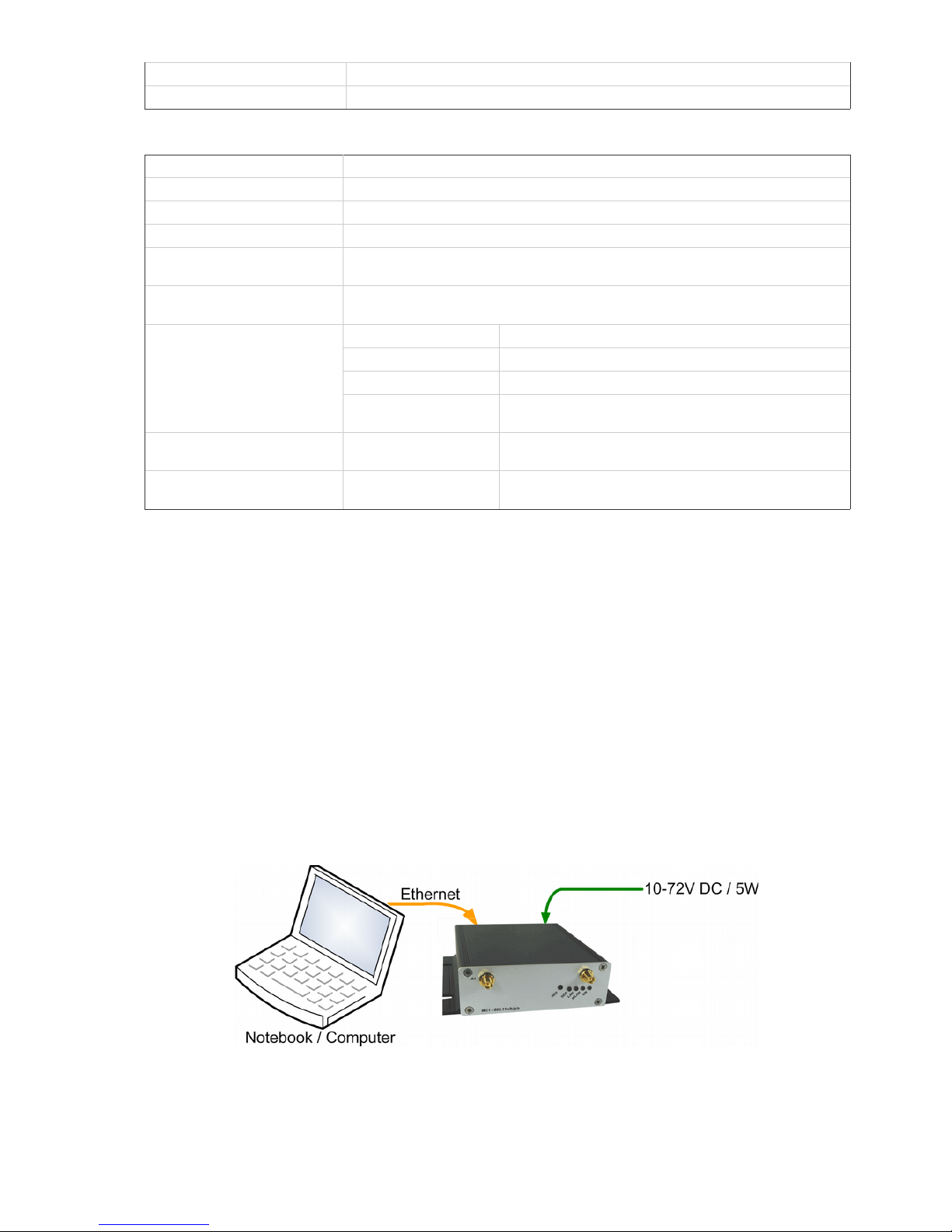
2 Initial startup
Please connect the MC via the Ethernet-Port with a PC using a patch cable for the initial startup.
When turning on power supply voltage, all LEDs briefly blink white. After that only the ON-LED lights up
green, which soon starts blinking orange (red & green) and green. This indicates the boot process. After
about 15 seconds the application is ready and the LEDs indicate the modes described above.
2.1 The MC-Config-Application
For its initial startup the MC is only able to communicate via its LAN-Port because typically there is no
wireless network with a suitable SSID.
MC Manual Version 2.10c
9
Figure 7: Setting for the initial configure of the MC
To do the „first time setup“ the MC has to be connected via the LAN-Interface to the computer (PC)
that runs the MC-Config-Program.
What to take into account:
- The connected PC (Notebook) should have a fixed IP-Address on its LAN-Port (no DHCP).
- The LAN-Port needs to be recognized as active by the operating system of the PC. You can check
the LAN-Port by entering “ipconfig” in the terminal.
- If the LAN-Port is recognized as active by the PC then press “Refresh” in the MC-Config-Application.
- An active Firewall on the PC might prevent communication with the MC.
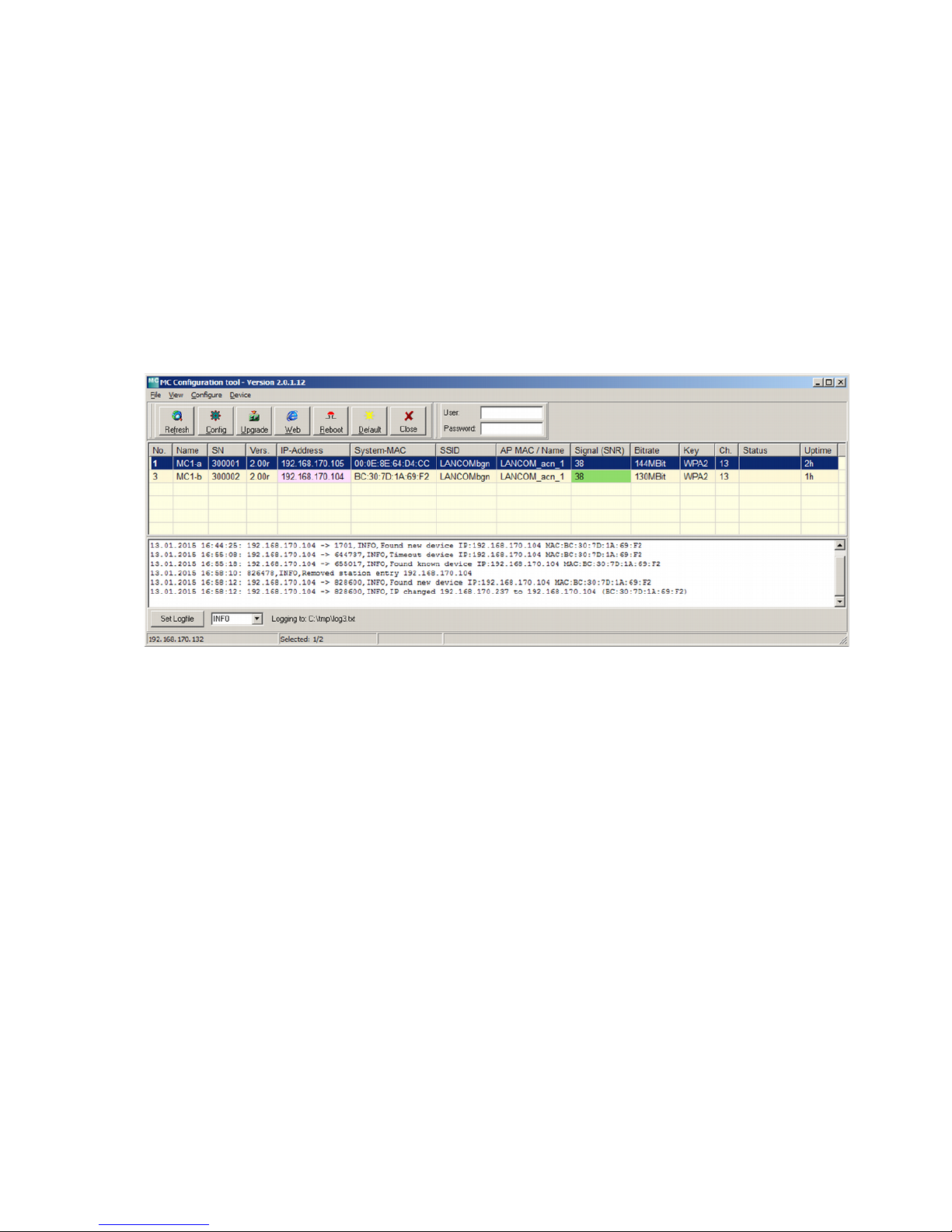
After launch, the MC-Config-Application first detects all network interfaces, that are currently active on the
PC. A Broadcast-UDP-Request is then sent out to all these interfaces and the MC devices will respond. The
responding devices will be registered and listed in the application.
Besides the device properties like name, serial number, software-version, IP-Address and MAC-Address, the
Wireless LAN connection details are displayed as well. Initially the set SSID is visible. As soon as a
connection to an Access-Point has been established the MAC-Address and the name of the AP are
displayed as well as the signal strength represented by a number and an equivalent background color. The
numbers can be interpreted as follows:
Signal >= 40 Very good connection
Signal >= 30 Good connection
Signal >= 20 Connection still sufficient
Signal < 20 Connection impaired, Bit rates are reduced in order to transfer data
How to use the MC-Config-Application is described in detail in a separate manual.
MC Manual Version 2.10c
10
Figure 8: Screenshot of the MC-Config-Application

2.2 Reset to factory settings
By pressing the reset-button for a long time, the MC can be set back to its factory settings. When keeping the
reset button pressed, the MC goes through different sequences that are visualized by all four LEDs lighting
up in the same color.
The LED-sequences start with lighting up in white, then blue, then red and then green; restarting with white
again. Holding the reset button pressed after the third time the all LEDs light up blue, the device is set back
to its factory settings. All LEDs are off during the reset to factory settings. After that, the reset button can be
released. When the reset button is released before the factory reset was initiated, then the MC needs to be
restarted by briefly pressing the reset button again.
The MC posses the following (important) factory settings:
Device Name: „MC“
SSID = „MC_WLAN“
Encryption mode = no encryption
MODE= 802.11 a/b/g/n (2.4 + 5 GHz)
IP = 192.168.170.100
Netmask = „255.255.255.0“
Gateway = 192.168.170.249
user = „“ (empty)
password = „“ (empty)
Serial 1: inactive
Relay: inactive
Input: inactive
MC Manual Version 2.10c
11
3 Setup of the parameters via Web-Interface
After having established a connection with the MC's http-Server via Web-Browser, a site with general
information about the MC as well as information about the current state of the device will be displayed. This
site can be accessed without the need of knowing the possibly set “User” + “Password”-combination.
Before being able to access any of the other sites, the “User” + “Password”-combination will be requested.
3.1 General Information
The first site that is visible contains general information regarding the current state of the device and about
its firmware.
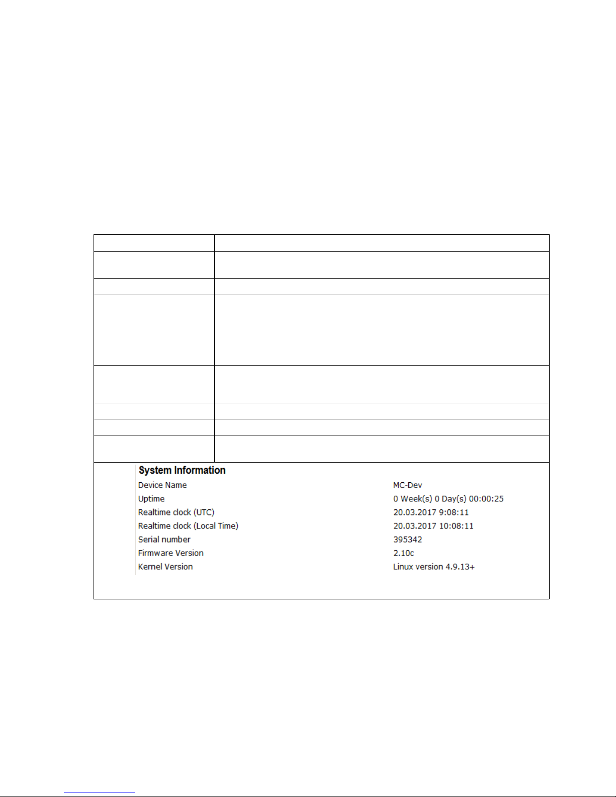
3.1.1 System Information
This section contains general information about the device:
Information Remark
Device Name This information can be edited under → Admin and is being displayed in the
MC-Config-Application as the device's name
Uptime This reflects the time since the MC was switched on or resetted the last time.
Realtime clock (UTC) This shows the internal device time. The MC sets the internal time by default
according to the time and date 2000.01.01 00:00:00
If a time server is set up though, (Configuration → Real Time Server) then the
MC will try to reach it and get the UTC information. If this is successful, the MC
changes the internal time accordingly. The internal time is used as a
timestamp for debug outputs.
Realtime clock
(Local Time)
since Firmware 2.09d
This is the time, taking into account the configured time zone.
Serial number The serial number assigned by the manufacturer.
Firmware Version The currently installed firmware on the device.
Kernel Version The MC firmware is based upon Linux. This version-number refers to the
Linux-version that has been used for the firmware.
Tabelle 3: System Information
MC Manual Version 2.10c
12

3.1.2 Wireless Status Information
This section contains information about the Wireless LAN state:
Operation Mode The MC can be used as a client in a Wireless LAN Infrastructure or as a device in
Adhoc Mode.
AP Mac Address
(BSSID)
This is the MAC-Address of the access point (AP) the MC is connected to. If the AP
transmits a device name, then the name will also be displayed here.
SSID (Network Name) This is the name of the Wireless LAN network the MC is supposed to or has
connected to.
Connection state State of the connection to the AP.
The shown status information depends on the configured authentication method:
Idle no connection active
Disconnected previously existing connection was interrupted
EAP Success completed EAP authentication
KeyCompleted key exchange completed
Connected WLAN connection established
Authenticate Authentication in process
Associate Association in process
Associated Association ready
EAP Started EAP Authentication in process
Timeout Timeout in EAP Authentication process
EAP Failed EAP Authentication failed
EAP Select Method EAP Authentication in process
Security Active encryption and authentication method
Connection time Duration of the connection between MC and the current AP
Bitrate The bitrate that is used to send data to the AP.
Channel/Frequency This is the channel number and frequency that is used for the connection to the AP
SNR (Signal-to-Noise
Ratio)
The SNR can be valued as follows :
SNR State
>= 40 very good condition
>= 30 good condition
>= 20 with this SNR the MC will start to scan for APs with a stronger signal
>= 10 weak signal! The MC will frequently scan for APs with a stronger signal.
The data throughput will be interfered
< 10 very weak signal. The connection can get lost.
Table 4: Wireless Status Information
MC Manual Version 2.10c
13
 Loading...