

Page 1
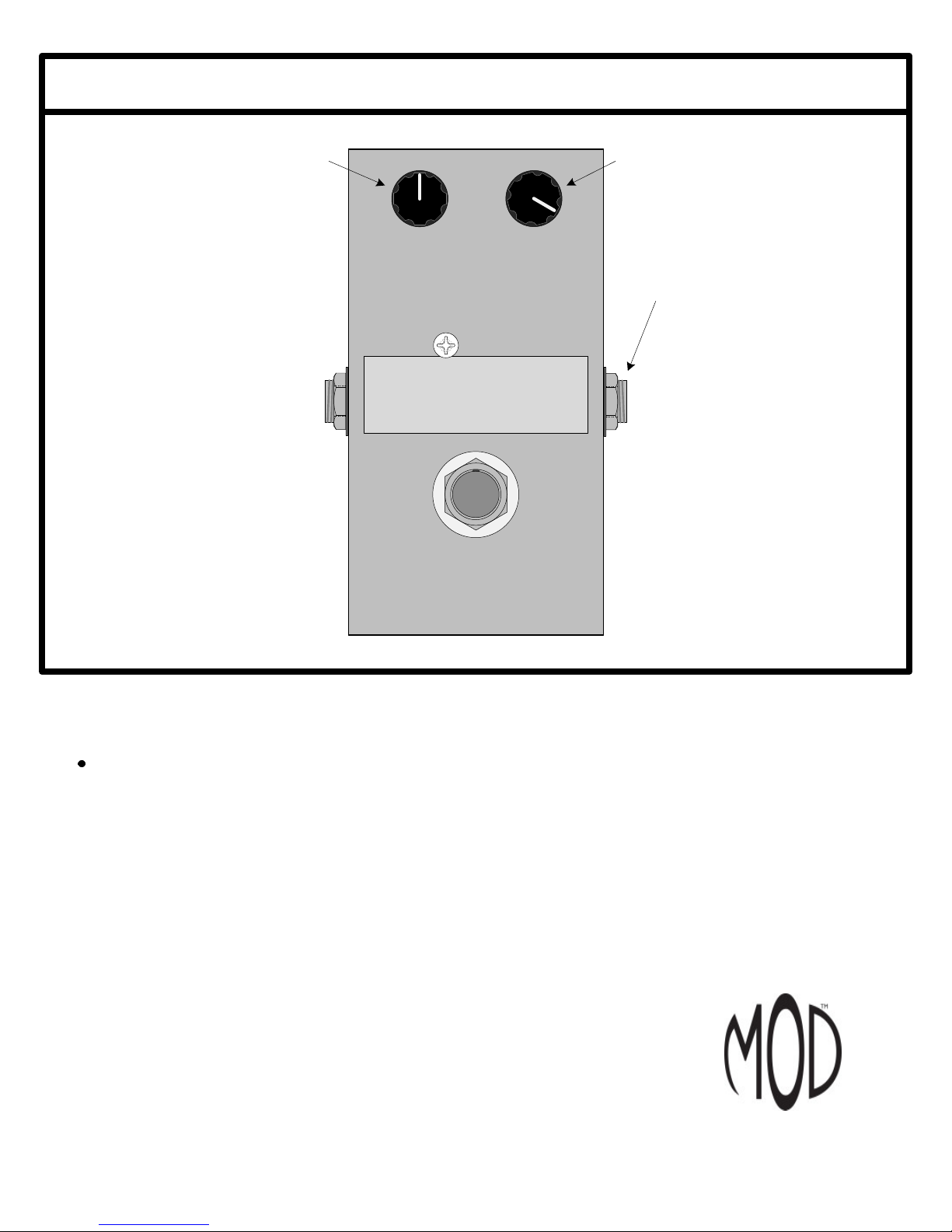
THE THUNDERDRIVE (K-950)
OUTPUT DISTORTION
Unplug when not in use
to save battery life.
TO
AMP
IN
The Thunderdrive
Modkitsdiy.com
FROM
GUITAR
OUT
Use these instructions to learn:
How to build an effects pedal for overdrive.
The Thunderdrive is an overdrive pedal kit that will provide a strong clean signal boost in the early gain
settings and smooth distortion at maximum gain settings. Adjusting output and distortion controls provides
a wide variety of tones in spite of its simple construction. It is capable of overdriving the preamp section of
your guitar amp or adding its own layer of distortion at lower volume.
www.modkitsdiy.com
1 Copyright © 2011 by modkitsdiy.com
Page 2

TABLE OF CONTENTS
TOOL LIST …………………………………………………………………………...2
PARTS LIST DRAWINGS………………………………………………………….3, 4
SOLDERING TIPS …………………………………………………………………...5
STEP BY STEP ASSEMBLY INSTRUCTIONS …………………………………...6
Section 1 – Mount ¼” Jacks and Terminal Strip Components ……………...6
Section 2 – Mount Potentiometers and Footswitch ………………………...7
Section 3 – Mount and Connect Remaining Components ………..…………..7
Section 4 – Wire Remaining Connections ...……………………………...7
ASSEMBLY DRAWINGS (4 Drawings) ……………………………………8, 9
These are the last 2 pages. They should be separated and used as a reference to help
assemble the kit correctly.
Visit www.modkitsdiy.com if you have any problems when first turning on your pedal for
troubleshooting help. Remember to use caution when applying power to the pedal to avoid electric
shock.
TOOL LIST
Wire Strippers
Needle Nose Pliers
Cutting Pliers
Desoldering Pump
Solder (60/40 rosin core)
Soldering Station
Phillips Head Screwdrivers
Slotted tip screwdrivers (3 mm tip)
Channellock Pliers (or similar type)
Ruler
Hobby Vise (or other means to secure box while working)
2
Page 3
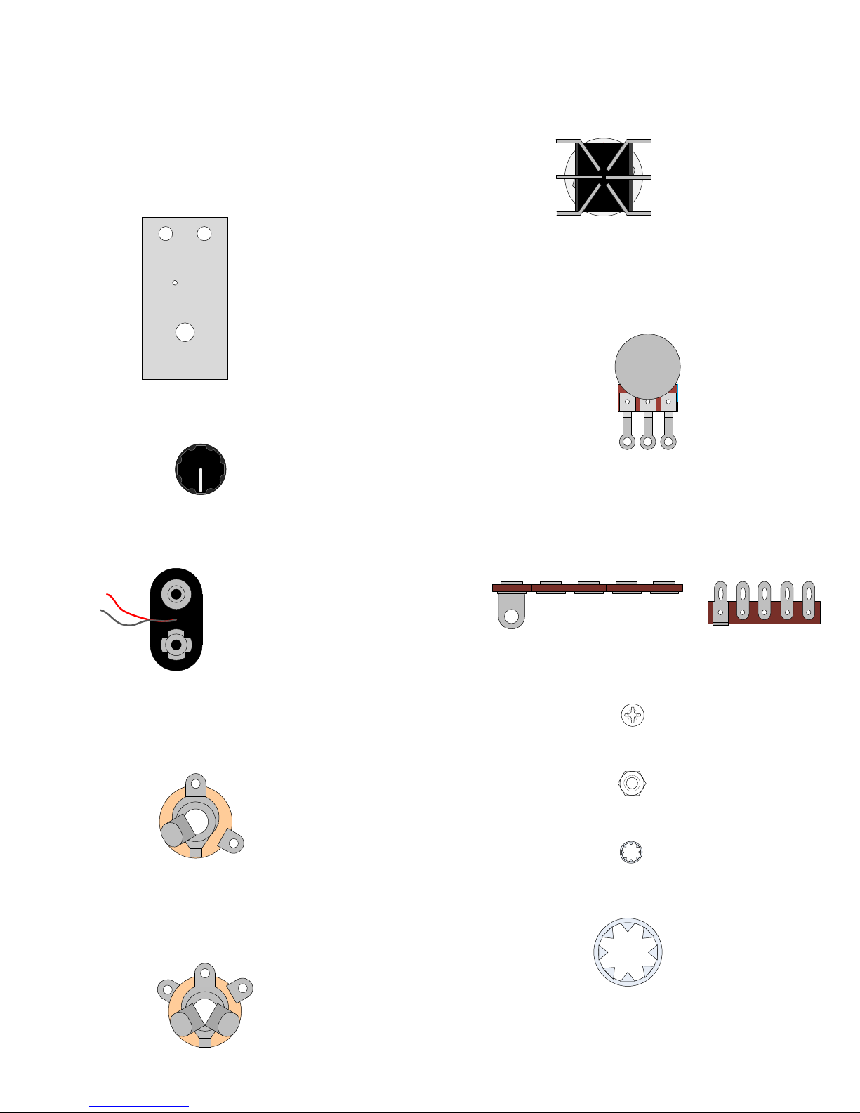
PARTS LIST 1
Stranded Wire (22 AWG) - Blue
S-W22BL (3 FT)
Enclosure
P-H1590BCE (1)
Knob (Scalloped Edge)
P-K801 (2)
DPDT Foot Switch
P-H498 (1)
250kΩ Potentiometer (Audio Taper)
R-VBM-250KA-SS (2)
1 2 3
Battery Clip
S-H155 (1)
¼” Mono Jack (Output Jack)
W-SC-11-T (1)
GROUND LUG
TIP LUG
¼” Stereo Jack (Input Jack)
W-SC-12B (1)
Terminal Strip with 5 Terminals
P-0501H01 (1)
#4 Screw (3/8" long)
S-HS440-38 (1)
#4 Nut
S-HHN440 (1)
#4 Lock Washer
S-HLW4 (1)
3/8" Lock Washer
S-HLW38 (2)
SLEEVE LUG
TIP LUG
RING LUG
3
Page 4
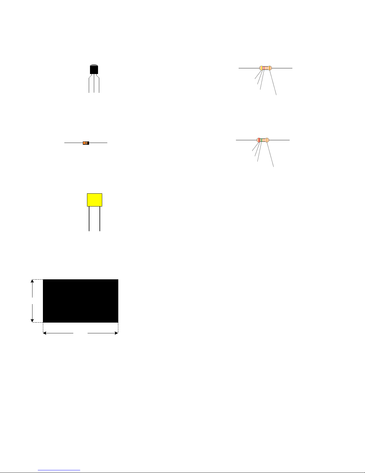
PARTS LIST 2
NPN BJT (MPSA18)
P-QMPSA18 (1)
MPS
A18
E B C
1N4148 HIGH SPEED SOLID STATE DIODE
P-Q971 (2)
0.1µF Capacitor 50V
C-PFD1-50-R (2)
104J
4.7kΩ Resistor ½ W
R-A4D7K (1)
4.7K
yellow
violet
red
gold
2MΩ Resistor ½ W
R-A2M (1)
2M
red
black
green
gold
Insulating Tolex
(Use to insulate the battery from the footswitch lugs)
S-G312
(1)
1"
1 ¾”
4
Page 5
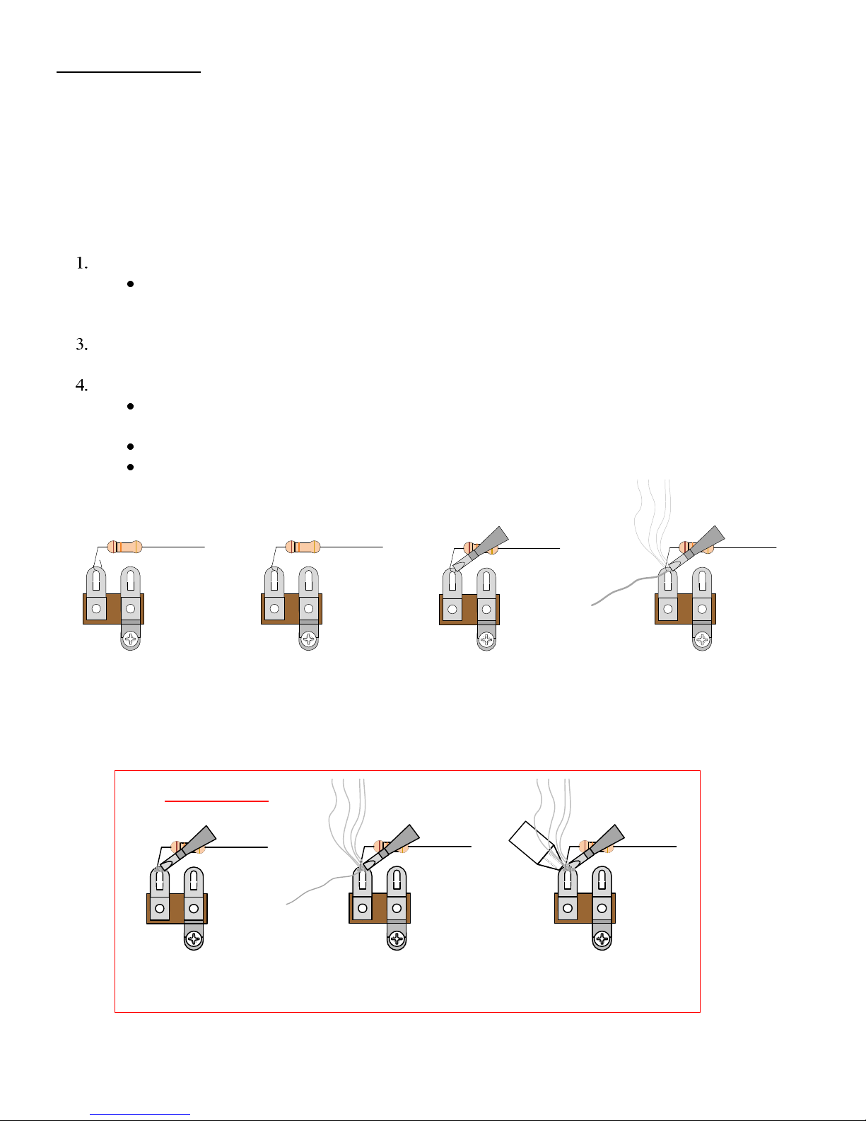
SOLDERING TIPS
It is important to make a good solder joint at each connection point. A cold solder joint is a connection that
may look connected but is actually disconnected or intermittently connected. (A cold solder joint can keep
your project from working.)
Follow these tips to make a good solder joint. Take your time with each connection and make sure that all
components are connected and will remain connected if your project is bumped or shaken.
Bend the component lead or wire ending and wrap it around the connection point.
Make sure it is not too close to a neighboring component which could cause an
unintended connection.
2. Wrap the component lead so that it can hold itself to the connection point.
Touch the soldering iron to both the component lead and the connection point allowing both to
warm up just before applying the solder to them.
Be sure to adequately cover both component lead and connection point with melted solder.
Remove the soldering iron from your work and allow the solder joint to cool. (The
solder joint should be shiny and smooth after solidifying.)
Cut off any excess wire or component leads with cutting pliers.
Clean the soldering iron's tip by wiping it across the wet sponge again after making the
solder joint.
1. Bend the component lead
and wrap it around the
connection point.
1. Heat up old solder joint
with the soldering iron.
2. Wrap the component lead
so that it can hold itself to the
De-Soldering Tip
connection point.
3. Heat up both component
lead and connection point with
2. Apply fresh solder to mix in
with old solder joint
5
the soldering iron.
3. Use a de-soldering tool to
remove the old solder joint
while it is heated.
4. Apply solder to both
component lead and
connection point.
Page 6
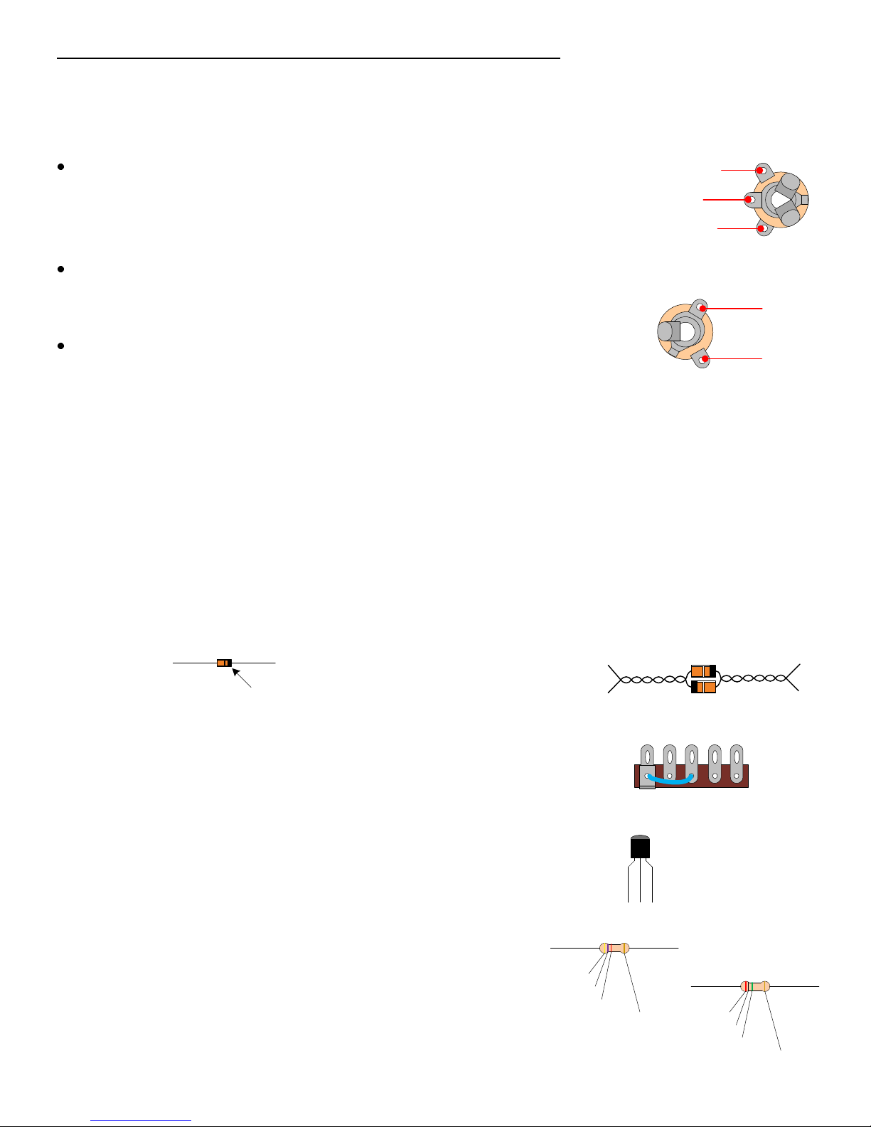
SECTION 1 – Mount ¼” Jacks and Terminal Strip Components
Please refer to DRAWING 1 and DRAWING 2.
Orient the box with ½” hole nearest you.
Mount input jack in 3/8" hole on left side of box with hardware provided.
Washer goes under nut on outside of box. Make sure center “ground” lug of input
jack is facing up. Correct positioning of jack will make soldering connections much
easier. When positioned correctly, tighten nut.
Mount output jack in 3/8" hole on right side of box with hardware provided.
Washer goes under nut on outside of box. Make sure the “tip” lug is on top
(towards the enclosure opening) before tightening nut.
Input Jack
RING LUG
GROUND LUG
TIP LUG
Output Jack
GROUND LUG
Mount the terminal strip to the 1/8" hole as shown in drawing 2.
We will refer to terminal numbers from “1” to “5” as illustrated.
TIP LUG
Unless noted otherwise, connect and solder all of the following to their respective connection points
as stated. (Make sure none of the component leads are so close together that they could lead to an
unintended connection). Be careful not to overheat the solid state devices (diodes and transistor)
when soldering.
1) Mount one end of the two diodes to terminal #1 on the terminal strip (leaving the other end free
for now). Make sure to connect the diodes with the reverse polarity of one another. In other words,
terminal #1 should be connected to one diode’s cathode as well as the other diode’s anode.
Keep the diode leads long so they can reach the volume pot to be mounted later in the instructions.
cathodeanode
cathode side is
marked with a
black band
2) Strip and tin a 1 ½” piece of wire and connect terminal #1 to #3.
You might want to connect to the lower terminal holes to leave room for other
components.
You might find it easier to mount
these diodes by twisting their
leads together first.
1 3
3) Mount the MPSA18 transistor to terminals 3, 4 and 5.
Terminals #3: Emitter
Terminals #4: Base
Terminals #5: Collector
4) Mount the 4.7K resistor to terminals 2 and 5.
5) Mount the 2M resistor to terminals 4 and 5. Do not solder.
Do not solder.
Do not solder.
6
yellow
violet
red
4.7K
MPS
A18
E B C
gold
2M
red
black
green
gold
Page 7
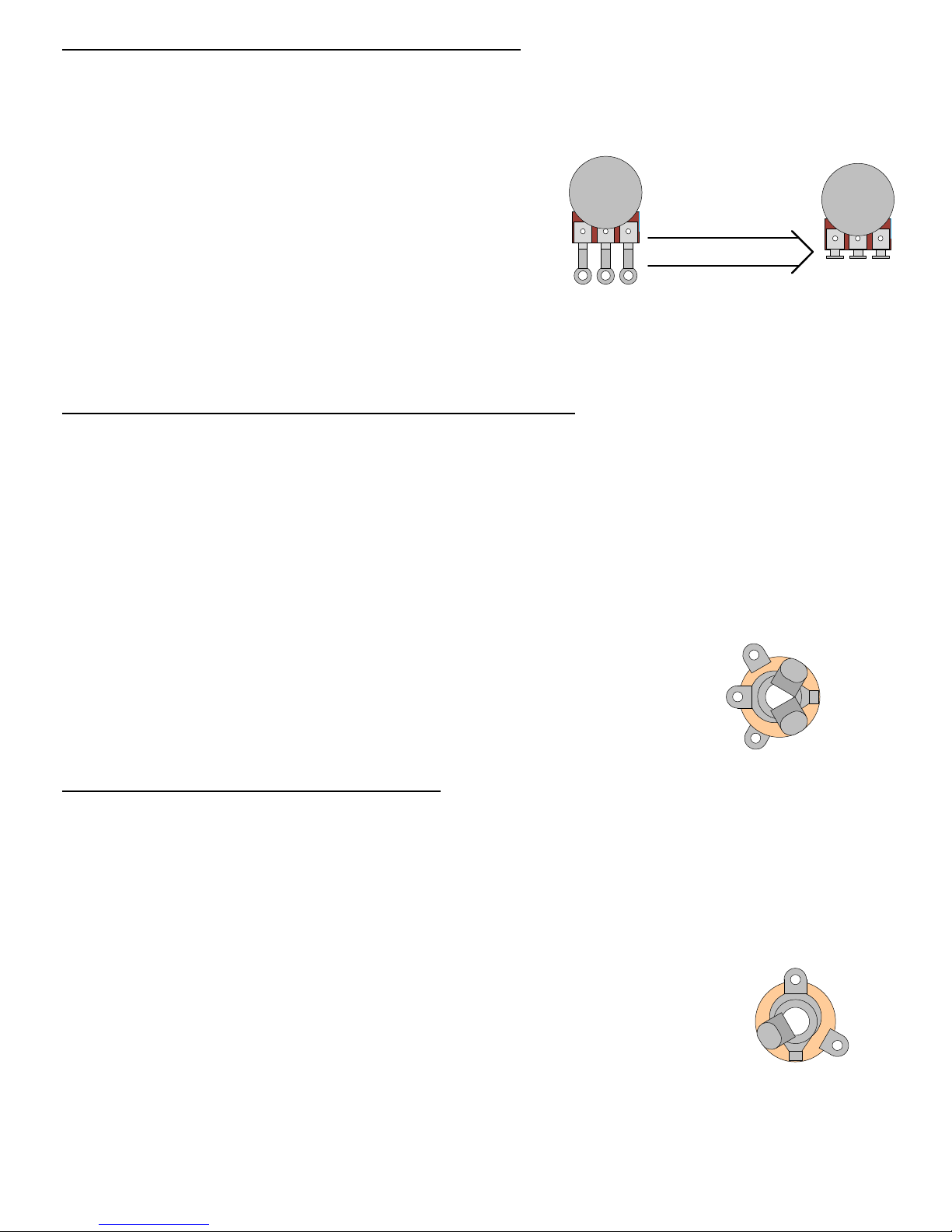
SECTION 2 – Mount Potentiometers and Footswitch
Please refer to DRAWING 3.
1) Mount the two 250K potentiometers in the 3/8" holes at the top of the enclosure using hardware
provided.
Before mounting, gently
bend the pot lugs back so
Remove nut and flat washer from potentiometers and
place large lock washers (S-HLW38) over shaft of each
they are pointing straight
up when mounted.
pot before inserting them through their mounting holes.
Fasten nut over flat washer and tighten.
1 2 3
1 2 3
2) Mount the DPDT footswitch in the ½” hole with its solder lugs oriented as in the drawing.
(The top hex nut and large plastic washer should be fastened on the outside of the box).
SECTION 3 – Mount and Connect Remaining Components
Please refer to DRAWING 4.
1) Connect the loose ends of the two diodes to output pot lug “1”. Do not solder.
2) Connect one of the 0.1µF capacitors to output pot lug “1” and terminal #5 of the terminal strip.
Solder all connections at output pot lug “1” and terminal #5 now.
3) Connect the other 0.1µF capacitor to terminal #4 and to both lugs “2” and “3” of the distortion pot.
Solder all connections at terminals #3, #4, #5 and distortion pot lugs “2” and “3” now.
4) Locate the battery clip. Cut 1 ½” length off the ends of each
RING LUG
lead and discard (or save for other projects). Connect the black
lead to the “ring” lug of the input jack. Connect the red lead to
SLEEVE LUG
terminal #2 of the terminal strip. Solder these connections now.
TIP LUG
SECTION 4 – Wire Remaining Connections
1) Strip and tin a 1 ½” piece of wire connect footswitch lugs “3” and “6”.
Leave the area behind the footswitch free from obstruction because it will be a tight fit for the 9V battery back there.
2) Strip and tin a 1" piece of wire and connect the input jack “tip” lug to the footswitch lug “2”.
3) Strip and tin a 3 ½” piece of wire and connect footswitch lug “1” to distortion pot lug “1”.
4) Strip and tin a 1 ¾” piece of wire and connect the output jack “ground” lug to
GROUND LUG
output pot lug “3”.
5) Strip and tin a 1 ¼” piece of wire and connect the output jack “tip” lug to
footswitch lug “5”.
6) Strip and tin a 3 ½” piece of wire and connect the output pot lug “2” to footswitch lug “4”.
Finish it off by double-checking all of your connections, connect and insert a 9V battery (with insulation), screw
the lid on and fasten the knobs to both pot shafts.
TIP LUG
7
Page 8
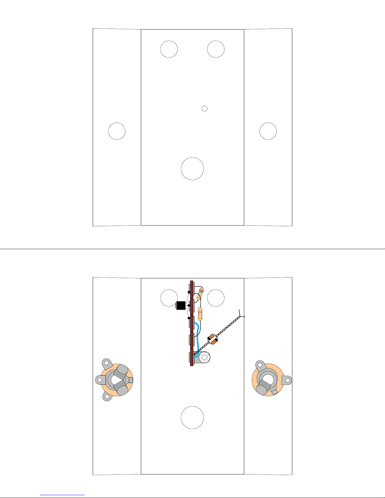
DRAWING 1
TOP
INSIDE VIEW OF THE
ENCLOSURE
1/8"
3/8" 3/8"
LEFT SIDE
1/2"
DRAWING 2
5
A18
MPS
2M
C
B
4.7K
E
RIGHT SIDE
INPUT JACK OUTPUT JACK
1
8
Page 9
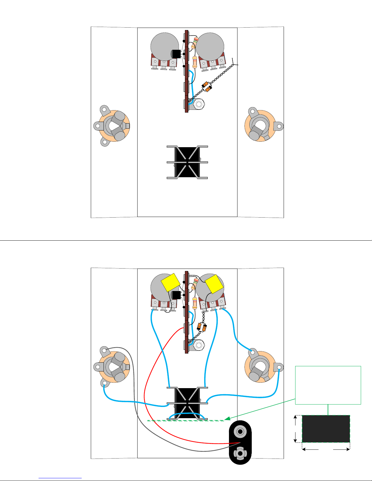
DRAWING 3
2M
5
A18
MPS
4.7K
1
2
3
3
2
1
INPUT JACK OUTPUT JACK
1
DRAWING 4
DISTORTION
POT
J
4
0
1
1
2
3
RED
2M
A18
MPS
4.7K
INPUT JACK OUTPUT JACK
BLK
1
2
3
OUTPUT
POT
1
0
4
J
3
2
1
4
5
6
Place the insulating tolex
between the battery and
footswitch lugs “3” and “6”
to prevent shorting the
signal to ground through the
battery case in bypass.
1"
1 ¾”
9
 Loading...