

Page 1

g
SLM-5650
Satellite Modem
Installation and O
IMPORTANT NOTE: The information contained in this document supersedes all
previously published information regarding this product. This manual is subject to
chan
e without prior notice.
Part Number MN/SLM5650.IOM Revision 2
peration Manual
Page 2

Page 3

Errata A
Comtech EF Data Documentation Update
Subject:
Date:
Original Manual
Part Number/Rev:
Errata Number:
Agile Document ID
Change Specifics:
This information will be incorporated into the next revision.
Front Cover – Removed “Prelimin
B.4 Basic Protocol
Changes to Front Cover and Section B.4, Basic Protocol
October 15, 2007
MN/SLM5650.IOM Rev 2
ER-SLM5650.EA2
ER-SLM5650.EA2
ary".
Agile CO Number
CO1453
Whether in EIA-232 or EIA-485 mode, all data is transmitted as asynchronous serial characters,
suitable for transmission and reception by a UART. In this case, the asynchronous character
format is 8N1. The baud rate may vary between 2400 and 57,600 baud.
AGILE DOC ID ER-SLM5650.EA2 THIS DOCUMENT IS NOT SUBJECT TO REVISION/UPDATE! AGILE CO1453
1
Page 4

This page is intentionally blank.
AGILE DOC ID ER-SLM5650.EA2 THIS DOCUMENT IS NOT SUBJECT TO REVISION/UPDATE! AGILE CO1453
2
Page 5
Subject:
Date:
Errata B
Comtech EF Data Documentation Update
Changes to Chapter 2. Installation
October 9, 2008
Original Manual
Part Number/Rev:
Agile Document ID
MN/SLM5650.IOM
ER-SLM5650.EB2
Agile CO Number
Rev 2
C05284
Change Specifics:
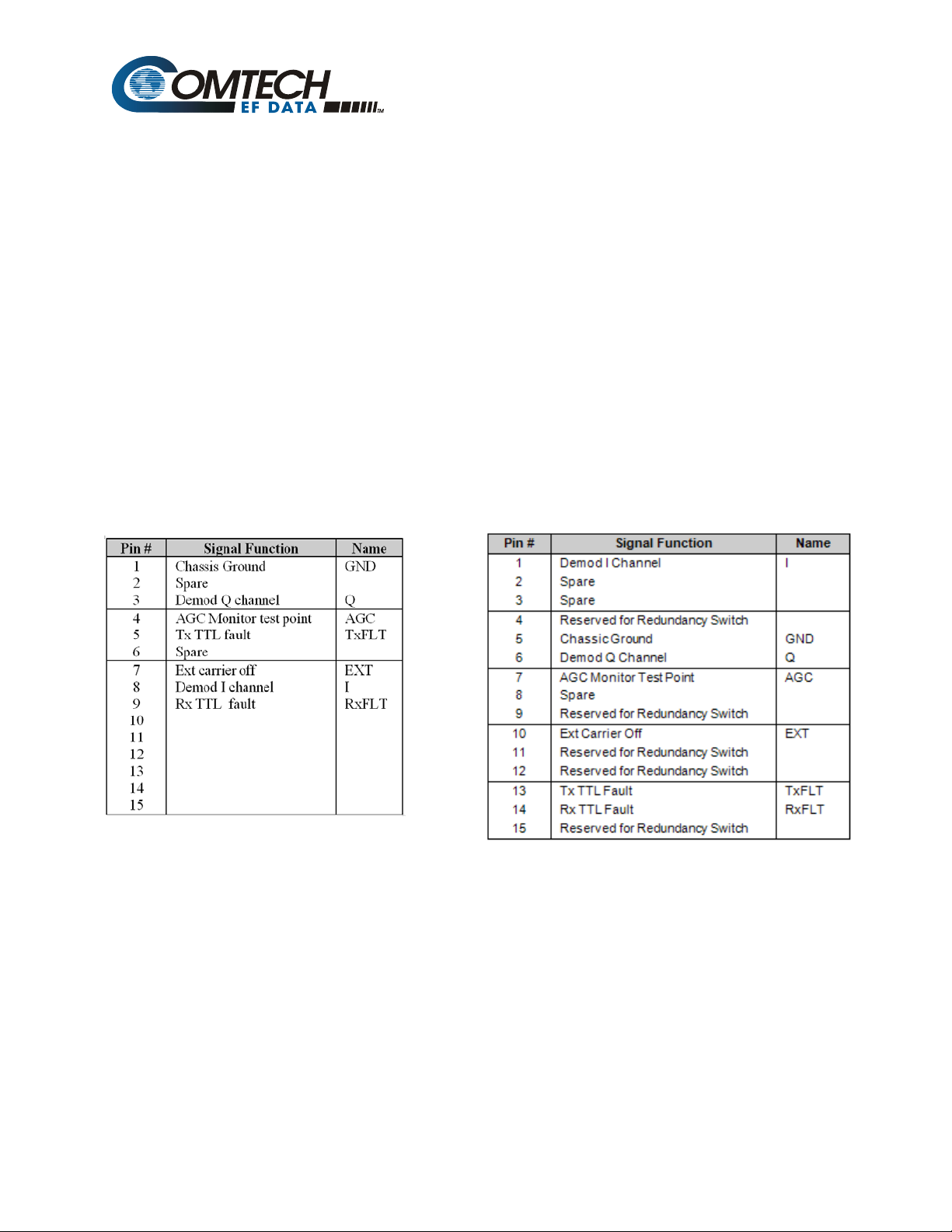
In Chapter 2. INSTALLATION, Sect. 2.3.8 Auxiliary Connector (J9), Page 2-9: Revise the pinout table for
the 15-pin connector as follows:
From: To:
This information will be incorporated into the next manual revision.
AGILE DOC ID ER-SLM5650.EB2 THIS DOCUMENT IS NOT SUBJECT TO REVISION/UPDATE! AGILE C05284
1
Page 6

This page is intentionally blank.
AGILE DOC ID ER-SLM5650.EB2 THIS DOCUMENT IS NOT SUBJECT TO REVISION/UPDATE! AGILE C05284
2
Page 7

SLM-5650
Satellite Modem
Installation and Operation Manual
Comtech EF Data is an ISO 9001
Re
gistered Company.
Part Number MN/SLM5650.IOM
Revision 2
August 19, 2006
Comtech EF Data, 2114 West 7th Street, Tempe, Arizona 85281 USA, 480.333.2200, FAX: 480.333.2161.
Copyright © Comtech EF Data, 2006. All rights reserved. Printed in the USA.
Page 8

Customer Support
Contact the Comtech EF Data Customer Support Department for:
• Product support or training
• Information on upgrading or returning a product
• Reporting comments or suggestions concerning manuals
A Customer Support representative may be reached at:
Comtech EF Data
Attention: Customer Support Department
2114 West 7th Street
Tempe, Arizona 85281 USA
480.333.2200 (Main Comtech EF Data Number)
480.333.4357 (Customer Support Desk)
480.333.2161 FAX
or, E-Mail can be sent to the Customer Support Department at:
service@comtechefdata.com
Contact us via the web at
1. To return a Comtech EF Data product (in-warranty and out-of-warranty) for
repair or replacement:
2. Request a Return Material Authorization (RMA) number from the Comtech EF
Data Customer Support Department.
3. Be prepared to supply the Customer Support representative with the model
number, serial number, and a description of the problem.
4. To ensure that the product is not damaged during shipping, pack the product in
its original shipping carton/packaging.
5. Ship the product back to Comtech EF Data. (Shipping charges should be
prepaid.)
For more information regarding the warranty policies, see Warranty Policy, p. xiii.
0Hwww.comtechefdata.com.
ii
Page 9

Table of Contents
CHAPTER 1. INTRODUCTION.............................................................................................................1–1
1.1 Introduction 1–1
1.1.1 Features....................................................................................................................................1–2
1.1.2 Options......................................................................................................................................1–3
1.2 Modem Design 1–3
1.3 Modem Description 1–3
1.4 Operating Modes 1–5
1.4.1 Closed Networks.......................................................................................................................1–5
1.4.2 Open Networks (INTELSAT) ....................................................................................................1–5
1.4.3 OM-73.......................................................................................................................................1–5
1.5 Data Interfaces 1–5
1.5.1 TIA/EIA-530..............................................................................................................................1–6
1.5.2 TIA/EIA-613 (HSSI)...................................................................................................................1–6
1.5.3 Gigabit Ethernet........................................................................................................................1–6
1.6 Independent Tx and Rx Function 1–6
1.7 Interoperability 1–7
1.7.1 Interoperability with Legacy Modems.......................................................................................1–7
1.7.2 Protection Switches..................................................................................................................1–7
1.8 Summary of Specifications 1–8
1.8.1 Performance...........................................................................................................................1–10
1.8.2 Acquisition and Timing Performance Requirements ..............................................................1–10
iii
Page 10

SLM-5650 Satellite Modem Revision 2
Preface
1.8.3 Data Quality Performance......................................................................................................1–11
1.8.3.1 OM-73 Compatible Mode Performance..................................................................1–11
1.8.3.2 MIL-STD-188-165A Compatible Mode Performance..............................................1–11
1.8.3.3 IESS-308 Compatible Mode Performance..............................................................1–12
1.8.3.4 IESS-309 Compatible Mode Performance..............................................................1–12
1.8.3.5 IESS-310 Compatible Mode Performance..............................................................1–12
1.8.3.6 16-QAM Coding Mode Performance.......................................................................1–12
1.8.3.7 Turbo Coding Mode Performance...........................................................................1–12
1.8.3.8 BER.........................................................................................................................1–13
1.8.3.8.1 BPSK/QPSK/Offset QPSK BER Performance, Veterbi Decoding.............1–13
1.8.3.8.2 BPSK/QPSK/Offset QPSK BER Performance, Veterbi Decoding and Reed- ..
Solomon......................................................................................................1–13
1.8.3.8.3 8-PSK BER Performance, Trellis Decoder.................................................1–14
1.8.3.8.4 8-PSK BER Performance, Trellis Decoder and Reed-Solomon.................1–14
1.8.3.8.5 16-QAM BER Performance, Viterbi Decoder and Reed-Solomon.............1–14
1.8.3.8.6 BER Performance, Turbo Products Code Decoding..................................1–15
1.8.4 BER Performance with Symmetrical Adjacent Carriers..........................................................1–16
1.8.5 BER Performance with Asymmetrical Adjacent Carriers........................................................1–17
1.9 Dimensional Envelope 1–18
CHAPTER 2. INSTALLATION..............................................................................................................2–1
2.1 Unpacking 2–1
2.2 Installation 2–2
2.2.1 Optional Installation of Side-Railings........................................................................................ 2–2
2.2.2 Optional Installation Using a Typical Customer Rack...............................................................2–3
2.3 External Connections 2–4
2.3.1 External Reference, (J1)..........................................................................................................2–5
2.3.2 70 / 140 IF Interface Connectors.............................................................................................. 2–5
2.3.3 L-Band IF Interface Connectors................................................................................................2–5
2.3.4 Ethernet Remote Cont rol Connector, (J5)................................................................................2–5
2.3.5 EIA-530 Connector, (J6)...........................................................................................................2–6
2.3.6 HSSI Connector, (J7)................................................................................................................2–7
2.3.7 Alarms Connector, (J8)............................................................................................................. 2–8
2.3.8 Auxiliary Connector, (J9)..........................................................................................................2–8
2.3.9 Remote Connector, (J10).........................................................................................................2–9
2.3.10 Overhead Data, (P1)...............................................................................................................2–10
2.4 AC Power Connector 2–11
2.5 Ground Connector (GND) 2–11
2.6 Gigabit Ethernet 2–11
iv
Page 11

SLM-5650 Satellite Modem Revision 2
Preface
CHAPTER 3. CONFIGURATION..........................................................................................................3–1
3.1 Modes 3–1
3.2 Clocking Options 3–11
3.2.1 IDR/IBS G.703 Master/Master................................................................................................3–11
3.2.2 IDR/IBS G.703 Master/Slave..................................................................................................3–11
3.3 Buffering 3–14
3.4 Doppler 3–17
3.5 Plesiochronous 3–18
3.6 Frame/Multiframe Length 3–19
3.6.1 Multiples of the Frame Length................................................................................................ 3–19
3.6.2 Total Buffer Length.................................................................................................................3–19
3.6.3 Converting B etween Bits and Seco nds..................................................................................3–19
CHAPTER 4. FRONT PANEL OPERATION........................................................................................4–1
4.1 Front Panel 4–1
4.1.1 LED Indicators..........................................................................................................................4–2
4.1.2 Front Panel Keypad..................................................................................................................4–4
4.1.3 Menu Matrix..............................................................................................................................4–5
4.2 Opening Screen 4–6
4.3 Main Menu 4–6
4.3.1 Select: Config............................................................................................................................4–7
4.3.1.1 Select: CONFIG: Transmit ........................................................................................4–8
4.3.1.2 Select: CONFIG: Receive .......................................................................................4–11
4.3.1.3 Select: CONFIG: Mode ...........................................................................................4–16
4.3.1.4 Select: Configuration: AUPC: Local........................................................................4–17
4.3.1.5 Select: CONFIG: Ref...............................................................................................4–18
4.3.1.6 Select: CONFIG: Mask............................................................................................4–18
4.3.1.7 Select: CONFIG: Reset...........................................................................................4–19
4.3.1.8 Select: CONFIG: Remote........................................................................................4–19
4.3.2 Select: Monitor........................................................................................................................4–21
4.3.2.1 Select: Monitor: Alarms...........................................................................................4–22
4.3.2.2 Select: Monitor: Event-Log......................................................................................4–24
4.3.2.3 Select: Monitor: Rx-Params....................................................................................4–25
4.3.2.4 Select: Monitor: Statistics........................................................................................4–25
4.3.2.5 Select: Monitor: GigaBit I/F Statistics......................................................................4–26
4.3.3 Select: Test.............................................................................................................................4–26
4.3.3 Select: Save/Load...................................................................................................................4–28
4.3.4 Select: Utility...........................................................................................................................4–28
4.3.4.1 Select: Utility: Firmware...........................................................................................4–29
4.3.4.2 Select: Utility: FAST ................................................................................................4–31
4.3.4.3 Display Screen Saver Status...................................................................................4–32
v
Page 12

SLM-5650 Satellite Modem Revision 2
Preface
CHAPTER 5. MAINTENANCE..............................................................................................................5–1
5.1 System Checkout 5–1
5.1.1 Checkout...................................................................................................................................5–2
5.1.2 Interface Checkout....................................................................................................................5–2
5.1.3 Modulator Checkout..................................................................................................................5–3
5.2 Demodulator Checkout 5–6
5.3 Fault Isolation 5–9
5.4 System Faults/Alarms 5–10
APPENDIX A. OPTIONS......................................................................................................................A–1
APPENDIX B. REMOTE CONTROL....................................................................................................B–1
APPENDIX C. FLASH UPGRADING ...................................................................................................C–1
APPENDIX D. ETHERNET MANAGEMENT........................................................................................D–1
APPENDIX E. CDI-70 GIGABIT ETHERNET INTERFACE.................................................................E–1
vi
Page 13

SLM-5650 Satellite Modem Revision 2
Preface
Figures
Figure 1-1. SLM-5650..............................................................................................................................1–1
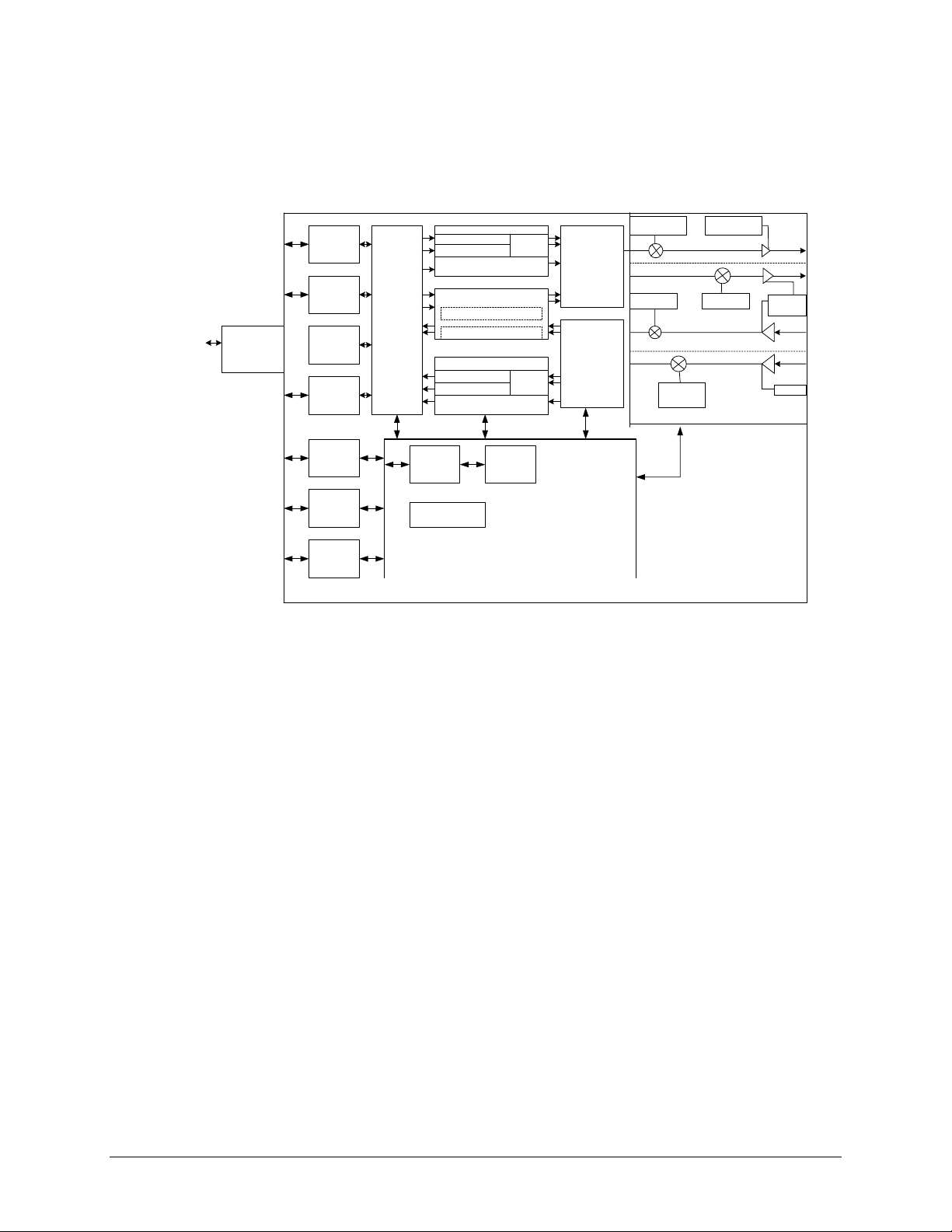
Figure 1-2. SLM-5650 Block Diagram......................................................................................................1–4
Figure 1-3. Dimensional Envelope.........................................................................................................1–18
Figure 2-1. Typical Installation of Side-Railings, FP/SL0006...................................................................2–2
Figure 2-2. Typical Customized Rack......................................................................................................2–3
Figure 2-3. Rear Panel.............................................................................................................................2–4
Figure 3-1. IDR/IBS G.703 Master/Master Clocking Diagram...............................................................3–12
Figure 3-2. IDR/IBS G.703 Master/Slave Clocking Diagram.................................................................3–13
Figure 3-3. Clock Slip.............................................................................................................................3–15
Figure 3-4. Doppler Shift........................................................................................................................3–16
Figure 4-1. Modem Front Panel...............................................................................................................4–1
Figure 4-2. Keypad...................................................................................................................................4–4
Figure E-1 10/100/1000 Base-T (GbE) Interface.....................................................................................E–1
Figure E-2. GbE Interface Optional Board................................................................................................E–4
Figure E-3. 1000 Base-T Ethernet (GbE) Card .......................................................................................E–5
vii
Page 14

SLM-5650 Satellite Modem Revision 2
Preface
Tables
Table 1-1. Summary of Specification.......................................................................................................1–8
Table 1-2. Acquisition and Timing Performance Requirements ............................................................1–10
Table 1-3. Doppler Requirements..........................................................................................................1–11
Table 1-4. Viterbi Decoder BER.............................................................................................................1–13
Table 1-5. Viterbi Decoder with Reed-Solomon BER............................................................................1–13
Table 1-6. 8-PSK BER Performance, Trellis Decoder...........................................................................1–14
Table 1-7. 8-PSK BER Performance, Trellis Decoder with Reed-Solomon .........................................1–14
Table 1-8. 16-QAM BER Performance, Viterbi Decoder with Reed-Solomon......................................1–14
Table 1-9. BER Performance, TPC Decoding .......................................................................................1–15
Table 1-10. Acceptable ACI Degradation with Spacing Factor of 1.2 ...................................................1–16
Table 3-1. OM-73 Mode............................................................................................................................3–1
Table 3-2. MIL-STD-188-165A Mode.......................................................................................................3–2
Table 3-3. IESS-308 Mode – Standard Higher Rates..............................................................................3–3
Table 3-4. IESS-308 Mode - Extended....................................................................................................3–6
Table 3-5. IESS-309 Mode – Extended (Closed Network)......................................................................3–8
Table 3-6. IESS-310 Mode – Extended Rates.........................................................................................3–9
Table 3-7. Turbo Code Mode...................................................................................................................3–9
Table 3-8. 16-QAM Mode.......................................................................................................................3–10
Table A-1. Viterbi Decoding Summary.....................................................................................................A–2
Table A-2. Open Network Modes.............................................................................................................A–4
Table A-3. Concatenated RS Coding Summary......................................................................................A–5
Table A-4. 8-PSK/TCM Coding Summary ...............................................................................................A–6
Table A-5. Available TPC Modes.............................................................................................................A–6
Table E-1. Interface Specifications..........................................................................................................E–2
Table E-2. Connector Pinout....................................................................................................................E–4
viii
Page 15

SLM-5650 Satellite Modem Revision 2
Preface
About this Manual
This manual describes the installation and operation for the Comtech EF Data SLM-5650
Satellite Modem. This is a technical document intended for earth station engineers, technicians,
and operators responsible for the operation and maintenance of the SLM-5650.
Related Documents
The following documents are referenced in this manual:
• Department of Defense (DOD) MIL-STD-188-114A, Electrical Characteristics of Digital
Interface Circuits
• Comtech EF Data Specification SP/11226
• INTELSAT Earth Station Standards 308 and 309
• EUTELSAT SMS
ix
Page 16
SLM-5650 Satellite Modem Revision 2
Preface
Conventions and References
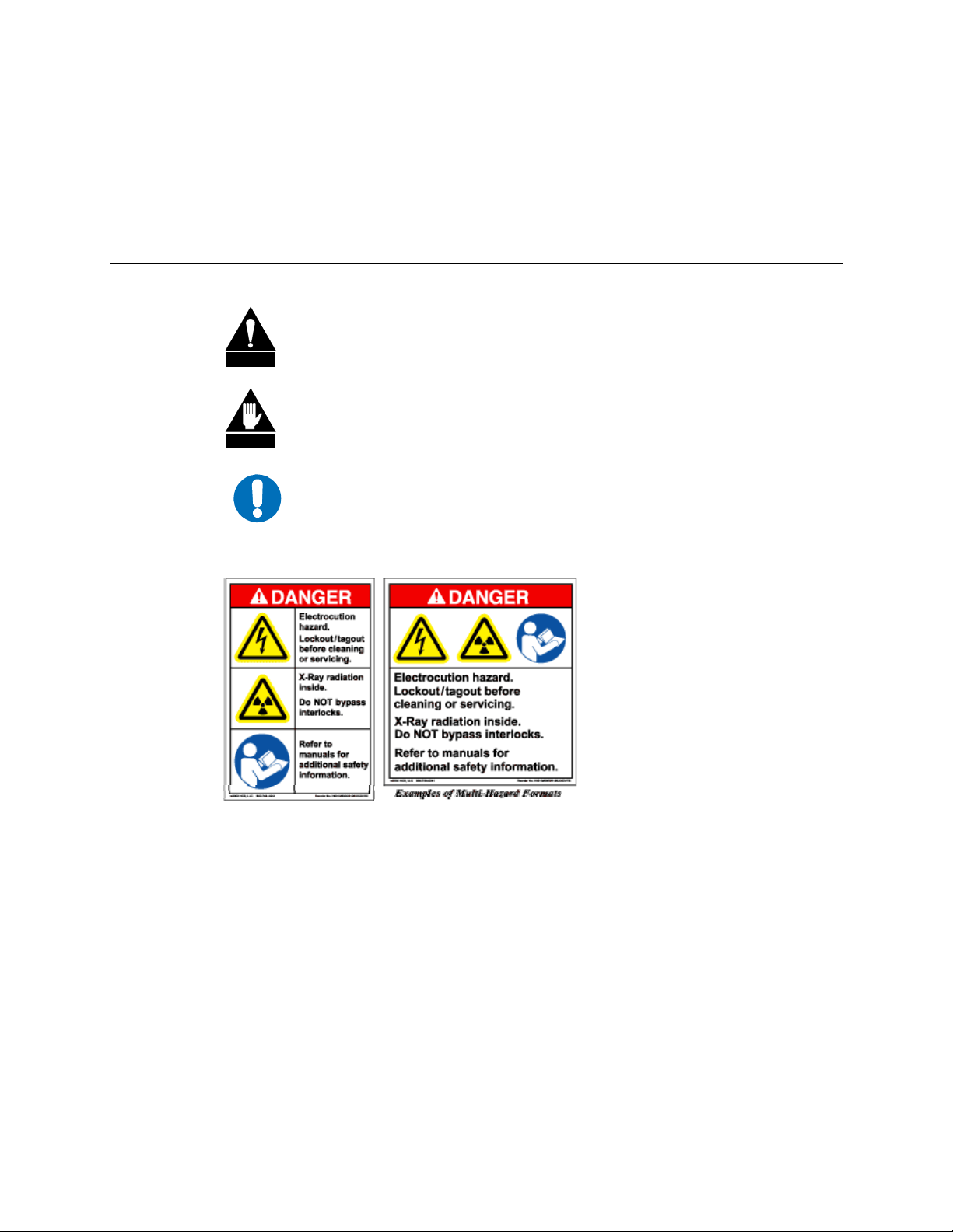
Cautions and Warnings
CAUTION indicates a hazardous situation that, if not avoided, may result in
minor or moderate injury. CAUTION may also be used to indicate other
CAUTION
WARNING
IMPORTANT
unsafe practices or risks of property damage.
WARNING indicates a potentially hazardous situation that, if not avoided,
could result in death or serious injury.
IMPORTANT indicates a statement that is associated with the task
being performed.
Examples of Multi-Hazard
Formats
x
Page 17

SLM-5650 Satellite Modem Revision 2
Preface
Metric Conversion
Metric conversion information is located on the inside back cover of this manual. This
information is provided to assist the operator in cross-referencing English to Metric conversions.
Recommended Standard Designations
Recommended Standard (RS) Designations are equivalent to the designation of the Electronic
Industries Association (EIA). Comtech EF Data will reference only one designator throughout the
manual.
Military Standards
References to “MIL-STD-188” apply to the 114A series (i.e., MIL-STD-188-114A), which
provides electrical and functional characteristics of the unbalanced and balanced voltage digital
interface circuits applicable to both long haul and tactical communications. Specifically, these
references apply to the MIL-STD-188-114A electrical characteristics for a balanced voltage
digital interface circuit, Type 1 generator, for the full range of data rates. For more information,
refer to the Department of Defense (DOD) MIL-STD-188-114A, Electrical Characteristics of
Digital Interface Circuits.
Trademarks
Product names mentioned in this manual may be trademarks or registered trademarks of their
respective companies and are hereby acknowledged.
Revision 2 Highlights
• Incorporated engineering changes throughout the manual.
• Revised Chapter 4, Front Panel Operation.
• Revised Appendix D, Ethernet Management.
• Revised Appendix E. 10/100/1000 Base-T (GbE) Interface
xi
Page 18
SLM-5650 Satellite Modem Revision 2
Preface
European EMC Directive
In order to meet the European Electro-Magnetic Compatibility (EMC) Directive (EN55022,
EN50082-1), properly shielded cables for DATA I/O are required. More specifically, these cables
must be shielded from end-to-end, ensuring a continuous ground shield.
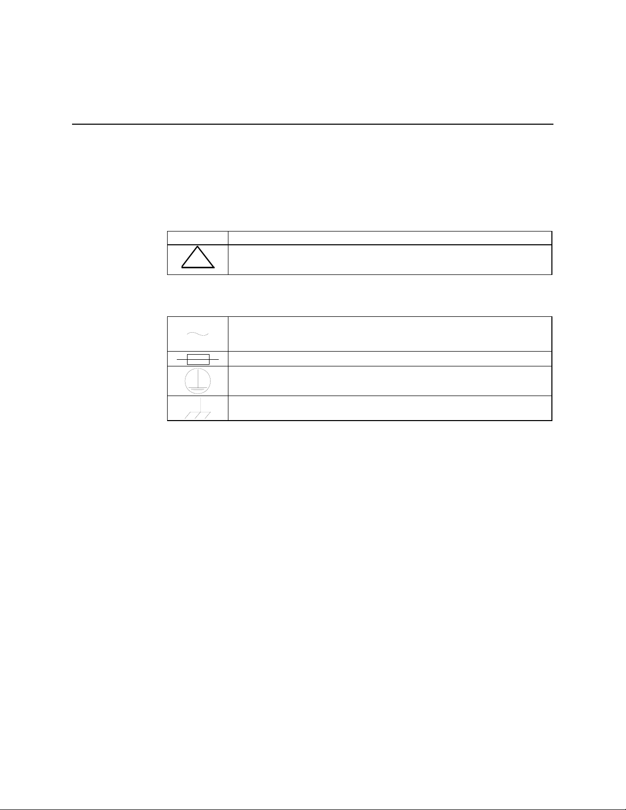
The following information is applicable for the European Low Voltage Directive (EN60950):
<HAR> Type of power cord required for use in the European Community.
CAUTION: Double-pole/Neutral Fusing
!
International Symbols:
ACHTUNG: Zweipolige bzw. Neutralleiter-Sicherung
Alternating Current.
Fuse.
Safety Ground.
Chassis Ground.
Note: For additional symbols, refer to “Cautions and Warnings” listed earlier in this
preface.
xii
Page 19

SLM-5650 Satellite Modem Revision 2
Preface
Warranty Policy
This Comtech EF Data product is warranted against defects in material and workmanship for a
period of one year from the date of shipment. During the warranty period, Comtech EF Data will,
at its option, repair or replace products that prove to be defective.
For equipment under warranty, the customer is responsible for freight to Comtech EF Data and all
related custom, taxes, tariffs, insurance, etc. Comtech EF Data is responsible for the freight
charges only for return of the equipment from the factory to the customer. Comtech EF Data will
return the equipment by the same method (i.e., Air, Express, Surface) as the equipment was sent
to Comtech EF Data.
Limitations of Warranty
The foregoing warranty shall not apply to defects resulting from improper installation or
maintenance, abuse, unauthorized modification, or operation outside of environmental
specifications for the product, or, for damages that occur due to improper repackaging of
equipment for return to Comtech EF Data.
No other warranty is expressed or implied. Comtech EF Data specifically disclaims the implied
warranties of merchantability and fitness for particular purpose.
Exclusive Remedies
The remedies provided herein are the buyer's sole and exclusive remedies. Comtech EF Data shall
not be liable for any direct, indirect, special, incidental, or consequential damages, whether based
on contract, tort, or any other legal theory.
Disclaimer
Comtech EF Data has reviewed this manual thoroughly in order that it will be an easy-to-use
guide to your equipment. All statements, technical information, and recommendations in this
manual and in any guides or related documents are believed reliable, but the accuracy and
completeness thereof are not guaranteed or warranted, and they are not intended to be, nor should
they be understood to be, representations or warranties concerning the products described.
Further, Comtech EF Data reserves the right to make changes in the specifications of the products
described in this manual at any time without notice and without obligation to notify any person of
such changes.
If you have any questions regarding your equipment or the information in this manual, please
contact the Comtech EF Data Customer Support Department.
xiii
Page 20

SLM-5650 Satellite Modem Revision 2
Preface
Notes:
______________________________________________________________________________
______________________________________________________________________________
______________________________________________________________________________
______________________________________________________________________________
______________________________________________________________________________
______________________________________________________________________________
______________________________________________________________________________
______________________________________________________________________________
______________________________________________________________________________
______________________________________________________________________________
______________________________________________________________________________
______________________________________________________________________________
______________________________________________________________________________
______________________________________________________________________________
______________________________________________________________________________
______________________________________________________________________________
______________________________________________________________________________
______________________________________________________________________________
______________________________________________________________________________
______________________________________________________________________________
______________________________________________________________________________
______________________________________________________________________________
______________________________________________________________________________
______________________________________________________________________________
______________________________________________________________________________
______________________________________________________________________________
______________________________________________________________________________
______________________________________________________________________________
______________________________________________________________________________
______________________________________________________________________________
______________________________________________________________________________
______________________________________________________________________________
______________________________________________________________________________
______________________________________________________________________________
______________________________________________________________________________
______________________________________________________________________________
______________________________________________________________________________
______________________________________________________________________________
______________________________________________________________________________
______________________________________________________________________________
xiv
Page 21
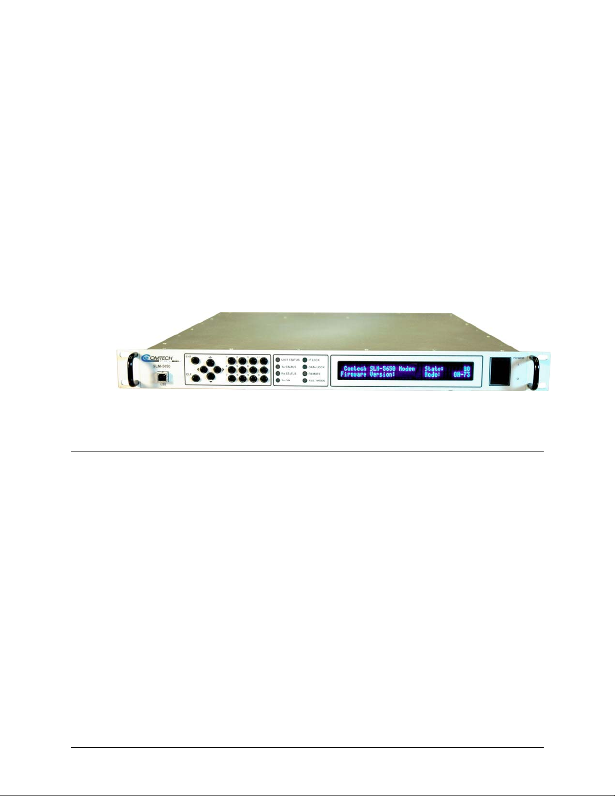
This chapter describes an overview of the SLM-5650 Satellite Modem, referred to in this
manual as “the modem” (Figure 1-1).
1.1 Introduction
The SLM-5650 satisfies the requirements for applications that require state-of-the-art modulation
and coding techniques to optimize satellite transponder bandwidth usage while retaining
backward compatibility in government and military communications systems. The initial release
of the modem supports base-band data rates up to 51.840 Mbps, and its flexible modulation and
Forward Error Correction (FEC) capabilities ensure that the throughput and BER over the
satellite is optimized.
Chapter 1. Introduction
Figure 1-1. SLM-5650
1–1
Page 22

SLM-5650 Satellite Modem Revision 2
Introduction MN/SLM5650.IOM
1.1.1 Features
The modem incorporates the following:
• MIL-STD-188-165A compliant (Types A, B, D, E, F)
• Intel-Sat IESS-308, -309, -310, and -315
• 64 kbps to 52 Mbps (Modulation, code rate, and interface dependent)
• Selectable 70/140 MHz or 950 to 2000 MHz IF interfaces
• BPSK, QPSK, OQPSK, 8-PSK, and 16-QAM
• Adaptive Equalizer for high order modulation types
• FEC Rates: 5/16, 1/2, 2/3, 3/4, 5/6, 7/8, 17/18 and 1/1
• Viterbi and Reed-Solomon Codec
• Turbo Product Codec (Optional)
• EIA-530/422 Data Interface (built in, to 20 Mbps)
• EIA-613/HSSI Data Interface (built in, to 52 Mbps)
• Optional Plug in Data Interface supports Gigabit Ethernet and others
• Data Source Bit Synchronization (Clock recovery for input data without an
associated transmit clock)
• Asymmetrical Loop Timing
• Full featured, built-in BER test-set
• Electrical and Ethernet Rx constellation monitor
• EIA-485 and EIA-232 interface for remote control
• Ethernet interface for remote control using HTTP, Telnet, and SNMP
• Flash upgrade capability
The modem is compliant with the provisions of MIL-STD-188-165A, DoD Standard,
Interoperability of SHF Satellite Communications PSK Modems (Frequency Division Multiple
Access (FDMA) Operation).
The modem is fully interoperable with legacy OM-73 modems and other Government owned
Commercial off-the-Shelf (COTS) and International Telecommunications Satellite Organization
(INTELSAT) compatible PSK modems.
The modem can be controlled and monitored from a variety of platforms, including its own front
panel controls and indicators, a co-located Personal Computer (PC) and remote control systems
such as the Comtech Monitor and Control System (CMCS) and the Vipersat Network
M
anagement System (VNMS).
1–2
Page 23

SLM-5650 Satellite Modem Revision 2
Introduction MN/SLM5650.IOM
1.1.2 Options
How Enabled Option
FAST Variable data rates from 64 kbps to 5, 10, 20, or 52 Mbps
FAST 8-PSK and 16-QAM
FAST Turbo Data Rates to 5, 10, 20, and 52 Mbps
FAST Automatic Uplink Power Control (AUPC)
Hardware Turbo FEC (Card)
Hardware Gigabit Ethernet Interface (Card)
1.2 Modem Design
The modem was designed to accommodate a wide range of currently required features and to be
able to support both near term and far term advances in both software defined radio technology as
well as advances in FEC technology.
The user has the ability to:
• Add or change modular data interfaces and FEC assemblies
• Utilize an extensive array of built in test capabilities
• Be able to easily upgrade the modems capability in the field
• Be able to easily upgrade the modems software in the field
• Have a wide range of flexible remote control options
The user can expect:
• A highly reliable modem
• Low weight and low power dissipation
• A rugged, one-rack unit enclosure that defines state of the art.
The modem is designed for installation in fixed or mobile Earth Terminal (ET) facilities (sites)
using Defense Satellite Communications System III (DSCS III), DSCS III/Satellite Life
Enhancement Program (SLEP), Wideband Gap filler System (WGS), and commercial satellites.
1.3 Modem Description
The modem accepts signals from a selected digital signal source and modulates either a 70/140
MHz or L-Band Intermediate Frequency (IF) carrier with these signals. The demodulator will
receive (Rx) a signal from either a 70/140 MHz or L-Band IF input interface, then demodulate
the IF carrier. Clock and data are recovered and output on a selected data interface.
The transmit and receive functions are independent with respect to coding, interleaving,
overhead, and scrambling. The modem will not allow simplex operation in the 70/140 and
simplex operation in the L-Band IF interfaces at the same time. The modem will allow duplex
operation in either one of the two IF interfaces.
1–3
Page 24
SLM-5650 Satellite Modem Revision 2
Introduction MN/SLM5650.IOM
64 kbps to 20 Mbps
64 kbps to 52 Mbps
Optional Interface
Gigabit Interface
Remote Port
Ethernet
Alarms
Data Interface
EIA-530
Data Interface
HSSI
Data Interface
Optional Slot
Overhaul Data
Interface
EIA-232
EIA-485
10/100
BaseT
Alarms
Tx/Rx
Baseband
Processing
Bit Error
Test Set
Reed-Solomon
Bypass
Bypass
Reed-Solomon
Bypass
Bypass
uP
Power Supply
Tx FEC
Viterbi
Optional FEC Slot
Slot#1 Turbo Tx/Rx
Slot#2 LDPC (Future)
Rx FEC
Viterbi
Keypad
&
Display
Constellation
Tx
Demodulator
Nyquist Filtering
Modulator
Nyquist
Filtering
Mapping
Acquisition
Rx Synth
Figure 1-2. SLM-5650 Block Diagram
70/140
Tx/Synth
L-Band
70/140
RX Synth
IF Sections
Power Control
L-Band
Tx Synth
Power
Control
AGC
AGC
Tx 70/140 MHz
Tx L-Band
Rx L-Band
RX 70/140 MHz
1–4
Page 25

SLM-5650 Satellite Modem Revision 2
Introduction MN/SLM5650.IOM
1.4 Operating Modes
The modem supports Closed Network, Open Network and OM-73 modes of operation
described as follows.
1.4.1 Closed Networks
Closed networks refer to private networks with modem operational parameters that do not need to
interoperate with modems developed for commercial open networks, as specified under the IESS308, IESS-309, and IESS-310.
The modem, however, is capable of operating in such closed networks over commercial satellites
IAW INTELSAT requirements for closed network operation.
A Comtech EF Data overhead channel is provided for use during Closed Network operation.
1.4.2 Open Networks (INTELSAT)
Open networks refer to networks that must meet INTELSAT specified Effective Isotropic
Radiated Power (EIRP), EIRP stability, spurious emissions, intermodulation products, adjacent
carrier interference, frequency tolerance, equalization, and modem parameters such as
modulation, FEC, and scrambling.
The modem meets INTELSAT certification requirements and is capable of operating in such
open networks over commercial satellites IAW IESS-308, IESS-309, and IESS-310 requirements
for open network operation.
In order to be fully compatible with commercial modems complying with IESS-308, IESS-309,
and IESS-310, the modem supports the overhead framing integral to those modems. It is
important to note that no access to the overhead channel data or alarms is provided.
1.4.3 OM-73
OM-73 mode allows the SLM-5650 to be compatible with Linkabit’s original OM-73 modem.
This modem and it’s operational capabilities have become a defacto standard when operating
over DSCS satellites. All OM-73 modes listed in MIL-STD-188-165A are supported.
1.5 Data Interfaces
The SLM-5650 supports two native data interfaces as well as a option slot for an additional
modular data interface. The two native interfaces are TIA/EIA-530/422 and TIA/EIA-613
(HSSI). The option interface available at this time is the Gigabit Ethernet. The modem will
currently support only one interface at a time.
1–5
Page 26

SLM-5650 Satellite Modem Revision 2
Introduction MN/SLM5650.IOM
1.5.1 TIA/EIA-530
The TIA/EIA-530 interface supports the physical layer requirements for TIA/EIA-530. It also
supports the TIA/EIA-422 electrical interface specification. This interface operates in duplex
from 64 kbps to 20 Mbps.
1.5.2 TIA/EIA-613 (HSSI)
The TIA/EIA-613 interface supports the physical layer requirements for TIA/EIA-613. It also
supports the TIA/EIA-612 electrical interface specification. This interface operates in duplex
from 64 kbps to 51.84 Mbps.
1.5.3 Gigabit Ethernet
In the SLM-5650, the GBEI-5650 performs a simple bridge function and passes IP packets,
unaltered, in each direction between the LAN (10/100/1000Base-T interface) and WAN (SLM5650 modulator/demodulator). IP packet traffic is framed via HDLC encapsulation by the GBE5650 logic, and the GBEI-5650 is both the origination and termination point for HDLC
encapsulation. HDLC CRC-16 verification is performed on all received (from WAN) HDLC
frames.
1.6 Independent Tx and Rx Function
The Tx (modulator) and Rx (demodulator) sides of the modem are functionally independent and
separately controllable. The baseband Tx and Rx sides of a communications channel passing
through the modem are independently configurable, including the ability to select different
parameters (to include data rate, modulation, and coding) in support of asymmetrical operation.
Note: Data interfaces and IF interfaces are not independent.
Example: If the TIA/EIA-530 interface is selected DO NOT USE TIA/EIA-530 to transmit and
a HSSI interface to receive. The same principle applies to the IF interfaces if 70/140 is selected
DO NOT USE 70/140 to transmit and the L-Band interface to receive.
1–6
Page 27

SLM-5650 Satellite Modem Revision 2
Introduction MN/SLM5650.IOM
1.7 Interoperability
1.7.1 Interoperability with Legacy Modems
The modem is fully compatible and interoperable with all specified modes of operation of the
following legacy modems:
a. OM-73 (V)
b. MD-1352 (P)/U (BEM-7650)
c. MD-1340 (OM-73 interoperable mode only; orderwire not required)
d. MD-1030B
e. SLM-3650
f. SLM-8650
SLM-7650
g.
Note: The remote control protocol will not be backwards compatible.
1.7.2 Protection Switches
Redundancy switching is accommodated with the following protection switches.
Compatible Non-Compatible
CRS-300, 1:10 redundancy switch SMS-300
CRS-311, 1:1 redundancy switch SMS-450
SMS-7000
1–7
Page 28

SLM-5650 Satellite Modem Revision 2
Introduction MN/SLM5650.IOM
1.8 Summary of Specifications
Table 1-1. Summary of Specification
Parameter Specification
Operating Frequency Range 52 to 88, 104 to 176, 950 to 2000 MHz,
in 100 Hz steps
Modulation Types BPSK, QPSK, OQPSK, 8-PSK, 16-QAM
Digital Data Rates 64 kbps to 5 Mbps, in 1 bps steps (EIA-530, EIA-613)
64 kbps to 10 Mbps, in 1 bps steps (EIA-530, EIA-613)
64 kbps to 20 Mbps, in 1 bps steps (EIA-530, EIA-613)
64 kbps to 51.840 Mbps, in 1 bps steps (EIA-613)
Symbol Rate Range 32 KS/S TO 30 MS/S
EXT REF Input TNC Connector, 1, 5, or 10 MHz selectable
INT REF Stability 1 x 10⁻⁷
Scrambling V.35, OM-73, and Synchronous
IDR/IBS Framing Compatibility Support for IBS and IDR framing. Allows basic IBS/IDR Open
Network capable operation.
Built-in Test (BIT) Fault and status reporting, BER performance monitoring, IF
Loop-back, programmable test modes, built in Fireberd
emulation with all comprehensive BER measurements.
Summary Faults Reported via Front Panel LEDs, 9-pin D sub Alarm connector,
relay contacts for Tx, Rx, Common equipment faults, and Tx
and RX alarms. Open collector faults on the 15-pin D sub Aux
connector. Both data interfaces have open collector faults
available.
Monitor and Control EIA-485, EIA-232, 10/100 BASET Ethernet with HTTP, Telnet,
and SNMP.
Modulator Specification
Output Power +10 – 40 dBm, adjustable in 0.1 dB steps
Output Return Loss -14 dB (70/140 MHz)
-9 dB (L-Band)
Output Impedance
Spurious
Harmonics From Carrier (CW) to the greater of the 12th harmonic or
Tx Clock Source Rx, INT, Tx Terrestrial, and Data Source Sync
Output Connections TNC for 52 to 88, 104 to 176 MHz
Modulation Timing Jitter
Modulation Phase Error
Modulator Spectral Inversion Modem can invert the modulated spectrum
Transmit Clock and Data
Inversion
50 Ω
From Carrier
10 kHz bandwidth)
4000 MHz –60 dBc
Type N for 950 to 2000 MHz
< 3 % of the modulation symbol period.
< 2 °
Modem can invert the Tx clock and data independently of each
other. (EIA-530, EIA-613)
± TX SR TO 500 MHZ –51 dBc (measured in a
1–8
Page 29

SLM-5650 Satellite Modem Revision 2
Introduction MN/SLM5650.IOM
Table 1-1. System Specification (Continued)
Demodulator Specification
Input Power:
Desired Carrier
Maximum Composite
Input Impedance
Input Connectors TNC for 52 to 88, 104 to 176
Carrier Acquisition Range
Input Return Loss -14 dB (70/140 MHz)
Buffer Clock INT, Tx Terrestrial, Rx Satellite
Doppler Buffer 32 to 4,194,304 bits, selectable in bits or mSec
Coding Options
Uncoded 1/1
Viterbi K=7, 1/2, 3/4, and 7/8 rates
Viterbi + Reed-Solomon Closed Network, per IESS-308, and IESS-309
Trellis IESS-310
Trellis + Reed-Solomon IESS-310
Turbo Turbo Product Coding (TPC), per IESS-315
Open Network Options
IDR INTELSAT IESS-308 (Framing only)
IBS INTELSAT IESS-310 (Framing only)
+10 to –55 dBm
+20 dBm or +40 dBc
50 Ω
Type N for 950 to 2000 MHz
±
30 kHz, selectable
-9 dB (L-Band)
INTELSAT IESS-310 (Framing only)
INTELSAT IESS-309 (Framing only)
1–9
Page 30

SLM-5650 Satellite Modem Revision 2
Introduction MN/SLM5650.IOM
1.8.1 Performance
1.8.2 Acquisition and Timing Performance Requirements
Note: The following reference Eb/No is defined as the required Eb/No corresponding to a
BER of IE-3 with R-S FEC not enabled.
Table 1-2. Acquisition and Timing Performance Requirements
Parameter Specification
Initial Acquisition
Reacquisition Reacquisition is achieved, as follows, after a period of up to 15 minutes of the
BCI With Tx and Rx random data, the mean time to loss of BCI due to falsely adding or
System Retention Synchronization and BCI are mainta ined for all Eb/N0 above the reference Eb/N0
Receive Timing Jitter
Doppler The modem meets the requirements with a Doppler shift, rate of change, and
The modem achieves initial acquisition within the times as specified within ± 30 kHz
at the reference Eb/No
• For baseband data rates between 64 kbps and ≤ 128 kbps, the maximum initial
acquisition time is 500 seconds.
• For Baseband data rates between 128kbps and ≤ 1544 kbps, the maximum
initial acquisition time is 30 seconds.
• For baseband data rates > 1544 kbps, the maximum initial acquisition time is
1.5 seconds.
absence of signal when the carrier returns to within 500 Hz of its original frequency.
• For baseband data rates between 64 kbps and 128 kbps, the maximum
reacquisition time shall be 45 seconds.
• For baseband data rates between 128 kbps and 1544 kbps, the maximum
reacquisition time shall be 20 seconds.
• For baseband data rates greater than 1544 kbps, the maximum reacquisition
time shall be 1 second.
deleting bits is at least 3 days at the reference E
maintains BCI over 50 consecutive bits of all ones or zeros, which occur no more than
once in 10,000 bits, without employing data scra mbl ing .
(BPSK/QPSK/OQPSK/8-PSK) for signal loss of up to 50 modulation symbol
periods, with a probability of at least 90 percent.
The Rx output clock peak timing jitter cannot exceed ± 5 percent at the reference
E
when the modulated signal meets the modulation timing jitter requirement.
b/N0
acceleration for satellite inclination up to ± 7° as presented in Table A-6, and an
additional 0.5 dB added to the reference E
b/N0
. In addition, the modem
b/N0
.
1–10
Page 31

SLM-5650 Satellite Modem Revision 2
Introduction MN/SLM5650.IOM
Table 1-3. Doppler Requirements
Parameter C-Band X-Band Ku-Band Ka-Band
Doppler Shift in Hz ± 2475 ± 3535 ± 6045 ± 11,810
Doppler Rate of Change in Hz/sec ± 226 ± 270 ± 490 ± 1046
Doppler Acceleration in Hz/sec2 ± 243 ± 290 ± 526 ± 112 4
1.8.3 Data Quality Performance
1.8.3.1 OM-73 Compatible Mode Performance
Operating in the OM-73-compatible mode, SLM-5650 BER vs. Eb/N0 performance with
differential encoding and data scrambling enabled does not exceed values shown in Table
1-4 though Table 1-9.
1.8.3.2 MIL-STD-188-165A Compatible Mode Performance
Operating with BPSK, QPSK, or OQPSK modulation in the MIL-STD-188-165A
compatible mode, SLM-5650 BER vs. E
data scrambling enabled will not exceed values shown in Table 1-4 (without ReedSolomon) or Table 1-5 (with Reed-Solomon) tested in an IF back-to-back configuration
over the BER range 5 x 10
-03
to 1 x 10
Operating with 8-PSK modulation and rate 2/3 pragmatic trellis coding (without ReedSolomon outer coding), SLM-5650 BER vs. E
the values shown in Table 1-6 when tested in an IF back-to-back configuration.
Operating with 8-PSK modulation, rate 2/3 pragmatic trellis coding, and Reed-Solomon
(219,201) outer coding, SLM-5650 BER vs. E
the values shown in Table 1-7 when tested in an IF back-to-back configuration.
performance with differential encoding and
b/N0
-07
.
performance is less than or equal to
b/N0
performance is better than or equal to
b/N0
1–11
Page 32

SLM-5650 Satellite Modem Revision 2
Introduction MN/SLM5650.IOM
1.8.3.3 IESS-308 Compatible Mode Performance
When operating in the IESS-308 Compatible Mode, SLM-5650 BER vs. Eb/N0
performance is as specified in IESS-308.
1.8.3.4 IESS-309 Compatible Mode Performance
When operating in the IESS-309 Compatible Mode, SLM-5650 BER vs. Eb/N0
performance is as specified in IESS-309.
1.8.3.5 IESS-310 Compatible Mode Performance
When operating in the IESS-310 Compatible Mode, SLM-5650 BER vs. Eb/N0
performance is as specified in IESS-310.
1.8.3.6 16-QAM Coding Mode Performance
The SLM-5650 operating in the 16-QAM mode provides back-to-back BER vs. Eb/N0
performance better than or equal to the values shown in Table 1-8 when using the
modulation formats indicated.
1.8.3.7 Turbo Coding Mode Performance
The SLM-5650 operating in the turbo code mode provides back-to-back BER vs. Eb/N0
performance better than or equal to the values shown in Table 1-9 when using the
modulation formats indicated.
1–12
Page 33

SLM-5650 Satellite Modem Revision 2
Introduction MN/SLM5650.IOM
1.8.3.8 BER
1.8.3.8.1 BPSK/QPSK/Offset QPSK BER Performance, Viterbi Decoding
Table 1-4 applies to BPSK, QPSK, and OQPSK rates.
Table 1-4. Viterbi Decoder BER
Eb/No (dB) Specification
Viterbi Decoder
BER 1/2 Rate 3/4 Rate 7/8 Rate Uncoded
10-3 3.8 5.0 6.3
10-4 4.7 5.9 7.1
10-5 5.3 6.6 7.8 10.8
10-6 5.9 7.2 8.4 11.6
10-7 6.5 7.8 9.0 12.4
10-8 7.1 8.3 9.5 13.0
1.8.3.8.2 BPSK/QPSK/Offset QPSK BER Performance, Viterbi Decoding and
Reed-Solomon
Table 1-5 applies to BPSK, QPSK, and OQPSK rates.
Table 1-5. Viterbi Decoder with Reed-Solomon BER
Eb/No (dB) Specification
Viterbi Decoder with reed-Solomon
BER 1/2 Rate 3/4 Rate 7/8 Rate
10-6 4.1 5.6 6.7
10-7 4.4 6.0 7.1
10-8 5.0 6.3 7.5
1–13
Page 34

SLM-5650 Satellite Modem Revision 2
Introduction MN/SLM5650.IOM
1.8.3.8.3 8-PSK BER Performance, Trellis Decoder
Table 1-6 applies to 8-PSK with trellis decoder rates.
Table 1-6. 8-PSK BER Performance, Trellis Decoder
Eb/No (dB) Specifications
Viterbi Decoder
BER 2/3 Rate 5/6 Rate
10-3 6.5 8.7
10-4 7.3 9.4
10-5 8.1 10.1
10-6 8.9 10.8
10-7 9.6 11.6
0-8
1
10.2 12.3
1.8.3.8.4 8-PSK BER Performance, Trellis Decoder and Reed-Solomon
Table 1-7 applies to 8-PSK with trellis decoder and reed-solomon rates.
Table 1-7. 8-PSK BER Performance,
Trellis Decoder with Reed-Solomon
Eb/No (dB) Specifications
Viterbi Decoder
BER 2/3 Rate 5/6 Rate
10-6 6.2 8.2
10-7 6.5 8.5
10-8 6.7 8.9
10-9 6.9 9.3
-10
10
7.2 9.7
1.8.3.8.5 16-QAM BER Performance, Viterbi Decoder and Reed-Solomon
Table 1-8 applies to 16-QAM with Viterbi decoder and reed-solomon rates.
Table 1-8. 16-QAM BER Performance,
Viterbi Decoder with Reed-Solomon
Eb/No (dB) Specifications
Viterbi Decoder
BER 3/4 Rate 7/8 Rate
10-6 8.2 9.5
10-7 8.4 9.8
10-8 8.6 10.1
10-9 8.8 10.3
-10
10
9.0 10.6
1–14
Page 35

SLM-5650 Satellite Modem Revision 2
Introduction MN/SLM5650.IOM
1.8.3.8.6 BER Perf ormance, Turbo Products Code Decoding
Table 1-9 applies to Turbo Products Code (TPC) decoding rates.
Table 1-9. BER Performance, TPC Decoding
Eb/No (dB) Specification
BPSK QPSK/OQPSK
BER 21/44 5/16 21/44 3/4 7/8 17/18
10-6 3.3 2.5 3.3 3.9 4.3 6.8
10-7 3.4 2.8 3.4 4.1 4.4 7.1
10-8 3.5 3.1 3.5 4.3 4.5 7.4
10-9 3.6 3.4 3.6 4.8 4.6 7.7
-10
10
3.7 3.7 4.7
Eb/No Specification
8-PSK 16-QAM
BER 3/4 7/8 17/18 3/4 7/8
10-6 6.5 7.1 10.0 7.6 8.2
10-7 6.9 7.2 10.6 8.0 8.4
10-8 7.2 7.3 11.2 8.4 8.5
10-9 7.5 7.4 11.8 8.7 8.7
-10
10
7.8 7.5 9.0 8.8
1–15
Page 36

SLM-5650 Satellite Modem Revision 2
Introduction MN/SLM5650.IOM
1.8.4 BER Performance with Symmetrical Adjacent Carriers
Operating in the presence of two adjacent symmetrical carriers (one lower in frequency and one
higher in frequency with same modulation, data rate, and coding), the modem performance is not
degraded more than as indicated in Table 1-10, Column three, and a and b. This performance is
measured with the adjacent carriers center frequencies offset XR
the carrier under test, where X is the spacing factor and R
is the modulation symbol rate in Hz of
s
the symmetrical carriers.
The BER of the test carrier is measured at the specified carrier Ratio of Energy per Symbol to
Noise Power Density in a 1 Hz Bandwidth (E
) Carrier to Noise Ratio (C/N) without the
s/N0
adjacent carriers. The adjacent ca rriers are a pplied at the specified center fre que ncies and E
the BER of the test carrier is measured. The change in BER is equal to the change in E
on the characterization curve of the test carrier and the amount of Adjacent Channel Interference
(ACI) degradation. For modulation symbol rates below 38.4 ksps, this paragraph does not apply.
Hz from the center frequency of
s
and
s/N0
based
b/N0
Table 1-10. Acceptable ACI Degradation with Spacing Factor of 1.2
Test
Carrier
Es/N0 (dB)
5.5 18.5 < 0.36 < 0.41
6.0 19.0 < 0.38 < 0.43
8.0 21.0 < 0.48 < 0.56
8.4 21.4 < 0.51 < 0.60
10.0 23.0 < 0.64 < 0.77
12.0 25.0 < 0.88 < 1.10
12.7 25.7 < 0.99 < 1.21
Adjacent
Carriers
Es/N0 (dB)
Eb/N0 Degradation
(dB)
Symmetric Case
Eb/N0 Degradation
(dB)
Asymmetric Case
a. For X (spacing factor) = 1.2, the symmetric degradation shall be IAW one of the values
in Table 1-17 Column three, and corresponding test carrier E
test carrier E
test configuration. The adjacent carriers E
that will yield timely results based on modulation and coding used in the
s/N0
shall be set to corresponding value in
s/N0
in Column one. Select a
s/N0
Column two.
b. For the case of X (spacing factor) = 1.4, the degradation is less than 0.2 dB.
1–16
Page 37

SLM-5650 Satellite Modem Revision 2
Introduction MN/SLM5650.IOM
1.8.5 BER Performance with Asymmetrical Adjacent Carriers
Operating in the presence of two adjacent asymmetrical carriers, one lower in frequency and one
higher in frequency, and each adjacent carrier symbol rate (R"
performance is not degraded more than indicated in Table 1-10, Column four, and a and b.
Performance is measured with the adjacent carriers center frequencies offset (X/2) times
(R'
+ R"s) Hz from the test carrier center frequency, where X is the spacing factor and R's is the
s
modulation symbol rate in Hz of the test carrier, and R"
s
each adjacent carrier. For modulation symbol rates below 38.4 ksps, this paragraph does not
apply.
) = 2.0 R's, the modem
s
is the modulation symbol rate in Hz of
a. For X (spacing factor) = 1.2, and R"
= 2.0 R's, the asymmetric degradation shall
s
be IAW one of the values in Table 1-10, Column four, and the corresponding test
carrier E
in Column one. Select a test carrier Es/N0 that will yield timely
s/N0
results based on modulation and coding used in the test configuration. The
adjacent carriers E
b. For the case of (1.4/2)(R'
are set to the corresponding value in Column two.
s/N0
+ R"s) Hz carrier spacing, the degradation is
s
< 0.2 dB.
1–17
Page 38

SLM-5650 Satellite Modem Revision 2
Introduction MN/SLM5650.IOM
1.9 Dimensional Envelope
Figure 1-3. Dimensional Envelope
1–18
Page 39

Chapter 2. INSTALLATION
This chapter provides unpacking and installation instructions, system options, and a
description of external connections and backward alarm information.
The equipment contains parts and assemblies sensitive to damage by
Electrostatic Discharge (ESD). Use ESD precautionary procedures when
CAUTION
2.1 Unpacking
The modem and manual are packaged in pre-formed, reusable, cardboard cartons
containing foam spacing for maximum shipping protection.
CAUTION
To remove the modem:
touching, removing, or inserting PCBs.
Do not use any cutting tool that will extend more than 1” into the container
and cause damage to the modem.
Step Procedures
1 Cut the tape at the top of the carton indicated by OPEN THIS END.
2 Remove the cardboard/foam space covering the modem.
3 Remove the modem, manual, and power cord from the carton.
4 Save the packing material for storage or reshipment purposes.
5 Inspect the equipment for any possible damage incurred during shipment.
6 Check the equipment against the packing list to ensure the shipment is
correct.
7 Refer to Section 2.2 for installation instructions.
2–1
Page 40

SLM-5650 Satellite Modem Revision 2
Installation MN/SLM5650.IOM
2.2 Installation
2.2.1 Optional Installation of Side-Railings
Install optional side-railings (FP/SL0006), as follows:
Quantity Part Number Description
2 FP/SL0006 Side-Railings
Use standard shop tooling. Install the side-railings with customer-furnished standard
shop hardware.
Figure 2-1. Typical Installation of Side-Railings, FP/SL0006
2–2
Page 41

SLM-5650 Satellite Modem Revision 2
Installation MN/SLM5650.IOM
2.2.2 Optional Installation Using a Typical Customer Rack
Step Procedures
1 Mount the modem chassis in the assigned position of the equipment rack.
Support the modem by either a rack-mounted shelf, or the two rear rackmounted brackets supplied with the unit.
Note: For a custom rack installation, refer to the rack drawing in
Figure 2-1. Additional information can be obtained from Comtech EF Data
Customer Support: www.comtechefdata.com
2 Connect the cables to the proper locations on the rear panel.
3 Before turning the power switch on, become familiar with front panel
operation in Chapter 4.
4 Turn on the power switch.
5 Check for the proper transmitter (TX) ou tput signal level and spectrum.
6 Check for proper receiver (RX) input signal level and function.
7 If there is any problem with the installation, refer to Chapter 5 for
troubleshooting information.
Note: Cool air is drawn in on the left side
and hot air is exhausted on the right side.
Figure 2-2. Typical Customized Rack
2–3
Page 42

SLM-5650 Satellite Modem Revision 2
Installation MN/SLM5650.IOM
2.3 External Connections
The connectors on the rear panel of the SLM-5650 are shown in Figure 2-4 and described in the
following paragraphs.
Name
EXT REF J1 TNC Modem Reference
Tx J11 TNC 70/140 MHz
Rx J3 TNC 70/140 MHz
Tx J2 Type N L-Band
Rx J4 Type N L-Band
Ethernet J5 RJ-45 10/100 Base-T, Remote Control
EIA-530 J6 25-Pin Female Data Input /Output, to 20 Mbps
HSSI J7 52-Pin Female Data Input /Output, to 52 Mbps
Overhead Data P1 25-Pin Male Not Used
Alarms J8 9-Pin Female Form-C Alarms
Auxiliary J9 15-Pin Female
Remote J10 9-Pin Female Remote Interface
AC IEC Modem Power
Ground 10-32 stud Chassis Grounding
Interface Option
Slot
Note: To maintain compliance with the European EMC Directive (EN55022, EN50082-1)
properly shielded cables are required for all data I/O.
Ref Des Connector Type Function
Supports optional data
interfaces, including but not
limited to the Gigabit Ethernet
Figure 2-3. Rear Panel
2–4
Page 43

SLM-5650 Satellite Modem Revision 2
Installation MN/SLM5650.IOM
2.3.1 External Reference, (J1)
The external reference uses a standard 50 Ω, TNC female connector.
TNC Connector Reference Description Direction
EXT REF J1 External Reference 1, 5, 10 MHZ Input
2.3.2 70 / 140 IF Interface Connectors
The 70 / 140 IF use standard 50 Ω, TNC female connectors.
TNC Connector Reference Description Direction
Rx J3 52-88, 104-176 MHz Receive Input
Tx J11 52-88, 104-176 MHz Transmit Output
2.3.3 L-Band IF Interface Connectors
The L-Band IF uses standard 50 Ω, Type N female connectors.
Type N Connector Reference Description Direction
Rx J4 950-2000 MHz Receive Input
Tx J2 950-2000 MHz Transmit Output
2.3.4 Ethernet Remote Control Connector, (J5)
The Ethernet connector is an 8-pin 'RJ-45' type 10/100 Base-T. Remote control of the modem is
provided using SNMP, HTTP or Telnet with this port.
2–5
Page 44

SLM-5650 Satellite Modem Revision 2
Installation MN/SLM5650.IOM
2.3.5 EIA-530 Connector, (J6)
The Data connector is a 25-pin ‘D’ type female (DB25-F). This connector conforms to the EIA530 pin-out for EIA-422 operation only.
Pin # Name
1 Ground
14 SD_B
2 SD_A
15 ST_A
3 RD_A
16 RD_B
4 RS_A
17 RT_A
5 CS_A
18 MOD FLT OC
6 DM_A
19 RS_B
7 Ground
20 Not Used
8 RR_A
21 DMD FLT OC
9 RT_B
22 DM_B
10 RR_B
23 Not Used
11 TT_B
24 TT_A
12 ST_B
25 Not Used
13 CS_B
2–6
Page 45

SLM-5650 Satellite Modem Revision 2
Installation MN/SLM5650.IOM
2.3.6 HSSI Connector, (J7)
Notes:
1. 52-pin connector
2. These are non-HSSI defined signals.
On Cisco routers there is no
connection to those pins.
Fault => Open
No Fault => Ground
Pin # Name
1 Ground
26 Ground
2 RT+
27 RT-
3 CA+
28 CA-
4 RD+
29 RD-
5 Not Used
30 Not Used
6 ST+
31 ST-
7 Ground
32 Ground
8 TA+
33 TA-
9 TT+
34 TT10 Not Used
35 Not Used
11 SD+
36 SD12 Not Used
37 Not Used
13 Ground
38 Ground
14 Not Used
39 Not Used
15 Not Used
40 Not Used
16 Not Used
41 Not Used
17 Not Used
42 Not Used
18 Not Used
43 Not Used
19 Ground
44 Ground
20 Not Used
45 Demod Fault see Note 2
21 Mod Fault see Note 2
46 Not Used
22 Not Used
47 Not Used
23 Not Used
48 Not Used
24 Not Used
49 Not Used
25 Ground
50 Ground
51 Ground
52 Ground
2–7
Page 46

SLM-5650 Satellite Modem Revision 2
Installation MN/SLM5650.IOM
2.3.7 Alarms Connector, (J8)
The alarm connector provides Form C contact closures for alarm reporting. The three Form C
summary fault contacts are Modulator, Demodulator Common Equipment.
The alarm connection is a 9-pin female D connector (J8) located on the rear panel of the modem.
Screw locks are provided for mechanical security on the mating connector.
Pin # Signal Function Name
8 Unit Alarm is faulted NO
3 Unit Alarm is not faulted NC
7 Unit Alarm common COM
5 Rx Alarm is faulted NO
9 Rx Alarm is not faulted NC
4 Rx Alarm common COM
2 Tx Alarm is faulted NO
6 Tx Alarm is not faulted NC
1 Tx Alarm common COM
2.3.8 Auxiliary Connector, (J9)
The auxiliary connector provides TTL open collector faults for the modulator and demodulator. A
TTL input for external transmit carrier mute. An Analog demodulator Q and I constellation
monitor. A programmable DC voltage monitor for the demodulators AGC.
(9-Pin Connector) The auxiliary connection is a 9-pin female D connector (J9) located on the rear
panel of the modem. Screw locks are provided for mechanical security on the mating connector.
Pin # Signal Function Name
1 Chassis Ground GND
2 Spare
3 Demod Q channel Q
4 AGC Monitor test point AGC
5 Tx TTL fault TxFLT
6 Spare
7 Ext carrier off EXT
8 Demod I channel I
9 Rx TTL fault RxFLT
2–8
Page 47

SLM-5650 Satellite Modem Revision 2
Installation MN/SLM5650.IOM
(15-Pin Connector) The auxiliary connection is a 15-pin female D connector (J9) located on the
rear panel of the modem. Screw locks are provided for mechanical security on the mating
connector.
Pin # Signal Function Name
1 Chassis Ground GND
2 Spare
3 Demod Q channel Q
4 AGC Monitor test point AGC
5 Tx TTL fault TxFLT
6 Spare
7 Ext carrier off EXT
8 Demod I channel I
9 Rx TTL fault RxFLT
10
11
12
13
14
15
2.3.9 Remote Connector, (J10)
The remote connector is a 9-pin subminiature female D connector (J6) located on the rear panel
of the modem. Screw locks are provided for mechanical security of the mating connector.
The remote connector interfaces the M&C functions to a remote location. The remote location can
be an M&C computer located away from the modem, but attached via cable to the remote
connector. This DCE interface is user selectable for either EIA-232 or EIA-484.
EIA-232 EIA-485
Pin #
5 GND 5 -Tx/Rx -Tx
9 9 -Tx/Rx -Rx
4 4 +Tx/Rx +Tx
8 CTS 8 +Tx/RX +Rx
3 TD 3
7 RTS 7
2 RD 2
6 DSR 6
1 GND 1
*For EIA-485 2-Wire Operation:
• Only two wires are required.
• Tie pins 4 and 8 together (both +).
• Tie pins 5 and 9 together (both -).
Name
Pinout
Pin #
Name
(2-Wire)
Name
(4-Wire)
2–9
Page 48

SLM-5650 Satellite Modem Revision 2
Installation MN/SLM5650.IOM
2.3.10 Overhead Data, (P1)
The overhead interface connector is a 25-pin male D interface located on the rear panel of the
modem.
This connector pin-out allows for connection of EIA-422, EIA-485 and EIA-232 data interfaces
for use with overhead framing. It also supports signaling for tactical applications
Pin #
1 EIA-422 Transmit Data “A”, Input Tx Data A
14 EIA-422 Transmit Data “B”, Input Tx Data B
2 EIA-422 Transmit Clock “A”, Output Tx Clk A
15 EIA-422 Transmit Clock “B”, Output Tx Clk B
3 EIA-422 Transmit Byte Sync “A”, Output Tx Sync A
16 EIA-422 Transmit Byte Sync “B”, Output Tx Sync B
4 EIA-422 Receive Data “A”, Output Rx Data A
17 EIA-422 Receive Data “B”, Output Rx Data B
5 EIA-422 Receive Clock “A”, Output Rx Clk A
18 EIA-422 Receive Clock “B”, Output Rx Clk B
6 EIA-422 Receive Byte Sync “A”, Output Rx Sync A
19 EIA-422 Receive Byte Sync “B”, Output Rx Sync B
7 Shield Ground
20 EIA-485 Transmit Data “-“ 485 Tx Data -
8 EIA-485 Transmit Data “+” 485 Tx Data +
21 EIA-422 Transmit Handover Sync “A”, Input THS A
9 EIA-485 Receive Data “-“ 485 Rx Data 22 EIA-485 Receive Data “+” 485 Rx Data +
10 EIA-422 Transmit Handover Sync “B”, Input THS B
23 EIA-232 Clear to Send 232 CTS
11 EIA-232 Receive Data 232 Rx Data
24 EIA-232 Request to Send 232 RTS
12 EIA-232 Transmit Data 232 Tx Data
25 EIA-422 Transmit Handover Control “A”, Input THC A
13 EIA-422 Transmit Handover Control “B”, Input THC B
Signal Function
*For EIA-485 2-Wire Operation:
• Only two wires are required.
• Tie pins 8 and 22 together (both +).
• Tie pins 9 and 20 together (both -).
Name
2–10
Page 49

SLM-5650 Satellite Modem Revision 2
Installation MN/SLM5650.IOM
2.4 AC Power Connector
A standard, detachable, non-locking, 3-prong power cord (IEC plug) supplies the Alternating
Current (AC) power to the modem. Observe the following:
Input Power
Input Voltage
Connector
Type
Fuse
Protection
65W maximum, 50W typical
90 to 132 or 175 to 264 VAC
Unit switches ranges automatically
I.E.C
1A slo-blo
Line and neutral fusing
5 mm type fuses
2.5 Ground Connector (GND)
A #10-32 stud on the rear panel of the modem is used for connecting a common chassis ground
among all equipment.
Note: The AC power connector provides the safety ground.
2.6 Gigabit Ethernet
The Gigabit Ethernet interface (AS/11985) supports 10/100/1000 BaseT operation. The LAN
interface is comprised of one IEEE 802.3ab 1000Base-T copper interface via a single female RJ45 connector (J1).
Pin # Description Direction
1 BI_DA+ bidirectional
2 BI_DA- bidirectional
3 BI_DB+ bidirectional
4 BI_DC+ bidirectional
5 BI_DC- bidirectional
6 BI_DB- bidirectional
7 BI_DD+ bidirectional
8 BI_DD- bidirectional
2–11
Page 50

SLM-5650 Satellite Modem Revision 2
Installation MN/SLM5650.IOM
This page is intentionally left blank.
2–12
Page 51

3.1 Modes
The following tables show the various data rate ranges available for various modes.
Chapter 3. Configuration
Table 3-1.
Data Rate
Modulation Type Min Max Min Max
BPSK 1/1 64 8472 64 10000
BPSK 1/2 64 15000 128 30000
BPSK 3/4 64 22500 85.333 29999.999
BPSK 7/8 64 26250 73.142 30000
QPSK 1/1 64 20000 32 10000
QPSK 1/2 64 30000 64 30000
QPSK 3/4 64 45000 42.666 30000
QPSK 7/8 64 51840 36.571 29622.857
OQPSK 1/ 1 64 20000 32 10000
OQPSK 1/ 2 64 30000 64 30000
OQPSK 3/ 4 64 45000 42.666 30000
OQPSK 7/ 8 64 51840 36.571 29622.857
OM-73 Mode
Symbol Rate (ksps)
(kbps)
3–1
Page 52

SLM-5650 Satellite Modem Revision 2
Configuration MN/SLM5650.IOM
Table 3-2. MIL-STD-188-165A Mode
Modulation
Type
Min Max Min Max
BPSK 1/1 Off N/A 64 8472 64 10000
BPSK 1/2 Off N/A 64 15000 128 30000
BPSK 3/4 Off N/A 64 22500 85.333 29999.999
BPSK 7/8 Off N/A 64 26250 73.142 30000
QPSK 1/1 Off N/A 64 20000 32 10000
QPSK 1/2 Off N/A 64 30000 64 30000
QPSK 3/4 Off N/A 64 45000 42.666 30000
QPSK 7/8 Off N/A 64 51840 36.571 29622.857
OQPSK 1/ 1 Off N/A 64 20000 32 10000
OQPSK 1/ 2 Off N/A 64 30000 64 30000
OQPSK 3/ 4 Off N/A 64 45000 42.666 30000
OQPSK 7/ 8 Off N/A 64 51840 36.571 29622.857
8-PSK 2/ 3 Off N/A 256 51840 128 25920
8-PSK 5/ 6 Off N/A 256 51840 102.4 20736
BPSK 1/2 126,112 4, 8 64 13333.333 144 29999.999
BPSK 1/2 219,201 4, 8 64 13767.123 139.462 29999.999
BPSK 1/2 225,205 4, 8 64 13666.666 140.487 29999.998
BPSK 1/2 220,200 4, 8 64 13636.363 140.8 29999.999
BPSK 3/4 126,112 4, 8 64 20000 96 30000
BPSK 3/4 219,201 4, 8 64 20650.684 92.975 29999.998
BPSK 3/4 225,205 4, 8 64 20500 93.658 29999.999
BPSK 3/4 220,200 4, 8 64 20454.545 93.867 29999.999
BPSK 7/8 126,112 4, 8 64 23333.333 82.826 30000
BPSK 7/8 219,201 4, 8 64 24092.465 79.692 29999.999
BPSK 7/8 225,205 4, 8 64 23916.666 80.278 29999.999
BPSK 7/8 220,200 4, 8 64 23863.636 80.457 30000
QPSK 1/2 126,112 4, 8 64 26666.666 72 29999.999
QPSK 1/2 219,201 4, 8 64 27534.246 69.371 29999.999
QPSK 1/2 225,205 4, 8 64 27333.333 70.243 29999.999
QPSK 1/2 220,200 4, 8 64 27272.727 70.4 30000
QPSK 3/4 126,112 4, 8 64 40000 48 30000
QPSK 3/4 219,201 4, 8 64 41301.369 46.487 29999.999
QPSK 3/4 225,205 4, 8 64 41000 46.829 30000
QPSK 3/4 220,200 4, 8 64 40909.090 46.933 30000
QPSK 7/8 126,112 4, 8 64 46666.666 41.143 30000
QPSK 7/8 219,201 4, 8 64 48184.931 39.846 29999.999
QPSK 7/8 225,205 4, 8 64 47833.333 40.139 29999.999
QPSK 7/8 220,200 4, 8 64 47727.272 40.229 30000
OQPSK 1/ 2 126,112 4, 8 64 26666.666 72 29999.999
OQPSK 1/ 2 219,201 4, 8 64 27534.246 69.371 29999.999
OQPSK 1/ 2 225,205 4, 8 64 27333.333 70.243 29999.999
OQPSK 1/ 2 220,200 4, 8 64 27272.727 70.4 30000
OQPSK 3/ 4 126,112 4, 8 64 40000 48 30000
OQPSK 3/ 4 219,201 4, 8 64 41301.369 46.487 29999.999
OQPSK 3/ 4 225,205 4, 8 64 41000 46.829 30000
OQPSK 3/ 4 220,200 4, 8 64 40909.090 46.933 30000
R-S Code
Word
R-S Depth Data Rate
(kbps)
Symbol Rate (ksps)
3–2
Page 53

SLM-5650 Satellite Modem Revision 2
Configuration MN/SLM5650.IOM
Modulation
Type
Min Max Min Max
OQPSK 7/ 8 126,112 4, 8 64 46666.666 41.143 30000
OQPSK 7/ 8 219,201 4, 8 64 48184.931 39.846 29999.999
OQPSK 7/ 8 225,205 4, 8 64 47833.333 40.139 29999.999
OQPSK 7/ 8 220,200 4, 8 64 47727.272 40.229 30000
8-PSK 2/ 3 126,112 4, 8 256 51840 144 29160
8-PSK 2/ 3 219,201 4, 8 256 51840 139.462 28241.194
8-PSK 2/ 3 225,205 4, 8 256 51840 140.487 28448.78
8-PSK 2/ 3 220,200 4, 8 256 51840 140.8 28512
8-PSK 5/ 6 126,112 4, 8 256 51840 115.2 23328
8-PSK 5/ 6 219,201 4, 8 256 51840 111.57 22592.955
8-PSK 5/ 6 225,205 4, 8 256 51840 112.39 22759.024
8-PSK 5/ 6 220,200 4, 8 256 51840 112.64 22809.6
R-S Code
Word
R-S Depth Data Rate
(kbps)
Symbol Rate (ksps)
Table 3-3.
Modulation
Type
QPSK 1/2 IESS-308 Off N/A 1544 1640
QPSK 1/2 IESS-308 Off N/A 2048 2144
QPSK 1/2 IESS-308 Off N/A 6312 6408
QPSK 1/2 IESS-308 Off N/A 8448 8544
QPSK 1/2 IESS-308 194,178 4, 8, 16 1544 1778.787
QPSK 1/2 IESS-308 194,178 4, 8, 16 2048 2328.09
QPSK 1/2 IESS-308 194,178 4, 8, 16 6312 6975.371
QPSK 1/2 IESS-308 194,178 4, 8, 16 8448 9303.371
QPSK 1/2 IESS-308 219,201 4, 8, 16 1544 1778.269
QPSK 1/2 IESS-308 219,201 4, 8, 16 2048 2327.403
QPSK 1/2 IESS-308 219,201 4, 8, 16 6312 6973.254
QPSK 1/2 IESS-308 219,201 4, 8, 16 8448 9300.537
QPSK 1/2 IESS-308 225,205 4, 8, 16 1544 1790.634
QPSK 1/2 IESS-308 225,205 4, 8, 16 2048 2343.805
QPSK 1/2 IESS-308 225,205 4, 8, 16 6312 7023.805
QPSK 1/2 IESS-308 225,205 4, 8, 16 8448 9368.195
QPSK 1/2 IESS-308 126,112 4, 8, 16 1544 1833
QPSK 1/2 IESS-308 126,112 4, 8, 16 2048 2400
QPSK 1/2 IESS-308 126,112 4, 8, 16 6312 7197
QPSK 1/2 IESS-308 126,112 4, 8, 16 8448 9600
QPSK 1/2 IESS-308 208,192 4, 8, 16 1544 1776.708
QPSK 1/2 IESS-308 208,192 4, 8, 16 2048 2325.333
QPSK 1/2 IESS-308 208,192 4, 8, 16 6312 6966.875
QPSK 1/2 IESS-308 208,192 4, 8, 16 8448 9292
QPSK 3/4 IESS-308 Off N/A 1544 1029.333
QPSK 3/4 IESS-308 Off N/A 2048 1365.333
QPSK 3/4 IESS-308 Off N/A 6312 4208
QPSK 3/4 IESS-308 Off N/A 8448 5632
QPSK 3/4 IESS-308 Off N/A 32064 21376
QPSK 3/4 IESS-308 Off N/A 34368 22912
QPSK 3/4 IESS-308 Off N/A 44736 29824
QPSK 3/4 IESS-308 194,178 4, 8, 16 1544 1217.858
Overhead R-S Code
IESS-308 Mode – Standard Higher Rates
Word
R-S Depth Data Rate
(kbps)
Symbol Rate
(ksps)
3–3
Page 54

SLM-5650 Satellite Modem Revision 2
Configuration MN/SLM5650.IOM
Modulation
Type
QPSK 3/4 IESS-308 194,178 4, 8, 16 2048 1584.06
QPSK 3/4 IESS-308 194,178 4, 8, 16 6312 4682.247
QPSK 3/4 IESS-308 194,178 4, 8, 16 8448 6324.247
QPSK 3/4 IESS-308 194,178 4, 8, 16 32064 23393.438
QPSK 3/4 IESS-308 194,178 4, 8, 16 34368 25067.506
QPSK 3/4 IESS-308 219,201 4, 8, 16 1544 1217.512
QPSK 3/4 IESS-308 219,201 4, 8, 16 2048 1583.602
QPSK 3/4 IESS-308 219,201 4, 8, 16 6312 4680.836
QPSK 3/4 IESS-308 219,201 4, 8, 16 8448 6232.358
QPSK 3/4 IESS-308 219,201 4, 8, 16 32064 23386.269
QPSK 3/4 IESS-308 219,201 4, 8, 16 34368 25059.821
QPSK 3/4 IESS-308 225,205 4, 8, 16 1544 1225.756
QPSK 3/4 IESS-308 225,205 4, 8, 16 2048 1594.537
QPSK 3/4 IESS-308 225,205 4, 8, 16 6312 4714.537
QPSK 3/4 IESS-308 225,205 4, 8, 16 8448 6277.463
QPSK 3/4 IESS-308 225,205 4, 8, 16 32064 23557.463
QPSK 3/4 IESS-308 225,205 4, 8, 16 34368 25243.317
QPSK 3/4 IESS-308 126,112 4, 8, 16 1544 1254
QPSK 3/4 IESS-308 126,112 4, 8, 16 2048 1632
QPSK 3/4 IESS-308 126,112 4, 8, 16 6312 4830
QPSK 3/4 IESS-308 126,112 4, 8, 16 8448 6432
QPSK 3/4 IESS-308 126,112 4, 8, 16 32064 24144
QPSK 3/4 IESS-308 126,112 4, 8, 16 34368 25872
QPSK 3/4 IESS-308 208,192 4, 8, 16 1544 1216.472
QPSK 3/4 IESS-308 208,192 4, 8, 16 2048 1582.222
QPSK 3/4 IESS-308 208,192 4, 8, 16 6312 4676.583
QPSK 3/4 IESS-308 208,192 4, 8, 16 8448 626.667
QPSK 3/4 IESS-308 208,192 4, 8, 16 32064 23364.667
QPSK 3/4 IESS-308 208,192 4, 8, 16 34368 25036.667
QPSK 7/8 IESS-308 Off N/A 1544 882.286
QPSK 7/8 IESS-308 Off N/A 2048 1170.286
QPSK 7/8 IESS-308 Off N/A 6312 3606.857
QPSK 7/8 IESS-308 Off N/A 8448 4827.428
QPSK 7/8 IESS-308 Off N/A 32064 20040.571
QPSK 7/8 IESS-308 Off N/A 34368 21473.714
QPSK 7/8 IESS-308 Off N/A 44736 27922.857
QPSK 7/8 IESS-308 194,178 4, 8, 16 1544 1057.592
QPSK 7/8 IESS-308 194,178 4, 8, 16 2048 1371.48
QPSK 7/8 IESS-308 194,178 4, 8, 16 6312 4027.069
QPSK 7/8 IESS-308 194,178 4, 8, 16 8448 5357.355
QPSK 7/8 IESS-308 194,178 4, 8, 16 32064 20065.233
QPSK 7/8 IESS-308 194,178 4, 8, 16 34368 21500.148
QPSK 7/8 IESS-308 194,178 4, 8, 16 44736 27957.265
QPSK 7/8 IESS-308 219,201 4, 8, 16 1544 1057.296
QPSK 7/8 IESS-308 219,201 4, 8, 16 2048 1371.087
QPSK 7/8 IESS-308 219,201 4, 8, 16 6312 4025.859
QPSK 7/8 IESS-308 219,201 4, 8, 16 8448 5355.736
QPSK 7/8 IESS-308 219,201 4, 8, 16 32064 20059.087
QPSK 7/8 IESS-308 219,201 4, 8, 16 34368 21493.561
QPSK 7/8 IESS-308 219,201 4, 8, 16 44736 27948.691
QPSK 7/8 IESS-308 225,205 4, 8, 16 1544 1064.362
QPSK 7/8 IESS-308 225,205 4, 8, 16 2048 1380.46
Overhead R-S Code
Word
R-S Depth Data Rate
(kbps)
Symbol Rate
(ksps)
3–4
Page 55

SLM-5650 Satellite Modem Revision 2
Configuration MN/SLM5650.IOM
Modulation
Type
QPSK 7/8 IESS-308 225,205 4, 8, 16 6312 4054.743
QPSK 7/8 IESS-308 225,205 4, 8, 16 8448 5394.397
QPSK 7/8 IESS-308 225,205 4, 8, 16 32064 20205.826
QPSK 7/8 IESS-308 225,205 4, 8, 16 34368 26150.843
QPSK 7/8 IESS-308 225,205 4, 8, 16 44736 28153.422
QPSK 7/8 IESS-308 126,112 4, 8, 16 1544 1088.571
QPSK 7/8 IESS-308 126,112 4, 8, 16 2048 1412.571
QPSK 7/8 IESS-308 126,112 4, 8, 16 6312 4153.714
QPSK 7/8 IESS-308 126,112 4, 8, 16 8448 5526.857
QPSK 7/8 IESS-308 126,112 4, 8, 16 32064 20708.571
QPSK 7/8 IESS-308 126,112 4, 8, 16 34368 22189.714
QPSK 7/8 IESS-308 126,112 4, 8, 16 44736 28854.857
QPSK 7/8 IESS-308 208,192 4, 8, 16 1544 1056.405
QPSK 7/8 IESS-308 208,192 4, 8, 16 2048 1369.905
QPSK 7/8 IESS-308 208,192 4, 8, 16 6312 4022.214
QPSK 7/8 IESS-308 208,192 4, 8, 16 8448 5350.857
QPSK 7/8 IESS-308 208,192 4, 8, 16 32064 20040.571
QPSK 7/8 IESS-308 208,192 4, 8, 16 34368 21473.714
QPSK 7/8 IESS-308 208,192 4, 8, 16 44736 27922.857
Overhead R-S Code
Word
R-S Depth Data Rate
(kbps)
Symbol Rate
(ksps)
3–5
Page 56

SLM-5650 Satellite Modem Revision 2
Configuration MN/SLM5650.IOM
Table 3-4.
Modulation
Type
Min Max Min Max
QPSK 1/2 None Off N/A 64 30000 64 30000
QPSK 1/2 None 126,112 4, 8, 16 64 26666.666 72 29999.999
QPSK 1/2 None 219,201 4, 8, 16 64 27534.246 69.371 29999.999
QPSK 1/2 None 194,178 4, 8, 16 64 27525.773 69.573 30000
QPSK 1/2 None 225,205 4, 8, 16 64 27333.333 70.243 29999.999
QPSK 1/2 None 208,192 4, 8, 16 64 27559.809 69.667 30000
QPSK 1/2 IESS-309 Off N/A 64 8448 68.267 9011.2
QPSK 1/2 IESS-309 126,112 4, 8, 16 64 8448 76.8 10137.6
QPSK 1/2 IESS-309 194,178 4, 8, 16 64 8448 74.403 9821.196
QPSK 1/2 IESS-309 225,205 4, 8, 16 64 8448 74.927 9890.341
QPSK 1/2 IESS-309 208,192 4, 8, 16 64 8448 74.311 9809.067
QPSK 3/4 None Off N/A 64 45000 42.666 30000
QPSK 3/4 None 126,112 4, 8, 16 64 40000 48 30000
QPSK 3/4 None 219,201 4, 8, 16 64 41301.369 46.487 29999.999
QPSK 3/4 None 194,178 4, 8, 16 64 41288.65 46.502 30000
QPSK 3/4 None 225,205 4, 8, 16 64 41000 46.829 30000
QPSK 3/4 None 208,192 4, 8, 16 64 41339.713 46.444 30000
QPSK 3/4 IESS-309 Off N/A 64 8448 45.511 6007.467
QPSK 3/4 IESS-309 126,112 4, 8, 16 64 8448 51.2 6758.4
QPSK 3/4 IESS-309 219,201 4, 8, 16 64 8448 49.587 6545.449
QPSK 3/4 IESS-309 194,178 4, 8, 16 64 8448 49.602 6547.464
QPSK 3/4 IESS-309 225,205 4, 8, 16 64 8448 49.951 6593.561
QPSK 3/4 IESS-309 208,192 4, 8, 16 64 8448 49.541 6539.378
QPSK 7/8 None Off N/A 64 51840 36.571 29622.857
QPSK 7/8 None 126,112 4, 8, 16 64 46666.666 41.143 30000
QPSK 7/8 None 219,201 4, 8, 16 64 48184.931 39.846 29999.999
QPSK 7/8 None 194,178 4, 8, 16 64 48170.103 38.859 30000
QPSK 7/8 None 225,205 4, 8, 16 64 47833.333 40.139 29999.999
QPSK 7/8 None 208,192 4, 8, 16 64 48229.665 39.81 29999.999
QPSK 7/8 IESS-309 Off N/A 64 8448 39.01 4827.428
QPSK 7/8 IESS-309 126,112 4, 8, 16 64 8448 43.886 5792.914
QPSK 7/8 IESS-309 219,201 4, 8, 16 64 8448 42.503 5610.385
QPSK 7/8 IESS-309 194,178 4, 8, 16 64 8448 42.516 5612.112
QPSK 7/8 IESS-309 225,205 4, 8, 16 64 8448 42.818 5561.624
QPSK 7/8 IESS-309 208,192 4, 8, 16 64 8448 42.463 5604.181
OQPSK 1/ 2 None Off N/A 64 30000 64 30000
OQPSK 1/2 None 126,112 4, 8, 16 64 26666.666 72 29999.999
OQPSK 1/2 None 219,201 4, 8, 16 64 27534.246 69.371 29999.999
OQPSK 1/2 None 194,178 4, 8, 16 64 27525.773 69.573 30000
OQPSK 1/2 None 225,205 4, 8, 16 64 27333.333 70.243 29999.999
OQPSK 1/2 None 208,192 4, 8, 16 64 27559.809 69.667 30000
OQPSK 1/ 2 IESS-309 Off N/A 64 8448 68.267 901.2
OQPSK 1/2 IESS-309 126,112 4, 8, 16 64 8448 76.8 10137.6
OQPSK 1/2 IESS-309 219,201 4, 8, 16 64 8448 74.38 9818.173
OQPSK 1/2 IESS-309 194,178 4, 8, 16 64 8448 74.403 9821.196
OQPSK 1/2 IESS-309 225,205 4, 8, 16 64 8448 74.927 9890.341
Overhead R-S Code
Word
IESS-308 Mode - Extended
R-S Depth Data Rate
(kbps)
Symbol Rate (ksps)
3–6
Page 57

SLM-5650 Satellite Modem Revision 2
Configuration MN/SLM5650.IOM
Modulation
Type
Min Max Min Max
OQPSK 1/2 IESS-309 208,192 4, 8, 16 64 8448 74.311 9809.067
OQPSK 3/ 4 None Off N/A 64 20000 42.666 30000
OQPSK 3/4 None 126,112 4, 8, 16 64 40000 48 30000
OQPSK 3/4 None 219,201 4, 8, 16 64 41301.369 46.487 29999.999
OQPSK 3/4 None 194,178 4, 8, 16 64 41288.65 46.502 30000
OQPSK 3/4 None 225,205 4, 8, 16 64 41000 46.829 30000
OQPSK 3/4 None 208,192 4, 8, 16 64 41339.713 46.444 30000
OQPSK 3/ 4 IESS-309 Off N/A 64 8448 45.511 6007.467
OQPSK 3/4 IESS-309 126,112 4, 8, 16 64 8448 51.2 6758.4
OQPSK 3/4 IESS-309 219,201 4, 8, 16 64 8448 49.587 6545.449
OQPSK 3/4 IESS-309 194,178 4, 8, 16 64 8448 49.602 6547.464
OQPSK 3/4 IESS-309 225,205 4, 8, 16 64 8448 49.951 6593.561
OQPSK 3/4 IESS-309 208,192 4, 8, 16 64 8448 49.541 6539.378
OQPSK 7/ 8 None Off N/A 64 20000 36.571 29622.857
OQPSK 7/8 None 126,112 4, 8, 16 64 46666.666 41.143 30000
OQPSK 7/8 None 219,201 4, 8, 16 64 48184.931 39.846 29999.999
OQPSK 7/8 None 194,178 4, 8, 16 64 48170.103 38.859 30000
OQPSK 7/8 None 225,205 4, 8, 16 64 47833.333 40.139 29999.999
OQPSK 7/8 None 208,192 4, 8, 16 64 48229.665 39.81 29999.999
OQPSK 7/ 8 IESS-309 Off N/A 64 8448 39.01 4827.428
OQPSK 7/8 IESS-309 126,112 4, 8, 16 64 8448 43.886 5792.914
OQPSK 7/8 IESS-309 219,201 4, 8, 16 64 8448 42.503 5610.385
OQPSK 7/8 IESS-309 194,178 4, 8, 16 64 8448 42.516 5612.112
OQPSK 7/8 IESS-309 225,205 4, 8, 16 64 8448 42.818 5561.624
OQPSK 7/8 IESS-309 208,192 4, 8, 16 64 8448 42.463 5604.181
Overhead R-S Code
Word
R-S Depth Data Rate
(kbps)
Symbol Rate (ksps)
3–7
Page 58

SLM-5650 Satellite Modem Revision 2
Configuration MN/SLM5650.IOM
Table 3-5.
Modulation
Type
Min Max Min Max
BPSK 1/2 None Off N/A 64 15000 128 30000
BPSK 1/2 None 219,201 4, 8, 16 64 13767.123 139.462 29999.999
BPSK 1/2 IESS-309 Off N/A 64 8448 136.533 18022.4
BPSK 1/2 IESS-309 219,201 4, 8, 16 64 8448 148.76 19636.346
BPSK 3/4 None Off N/A 64 22500 85.333 29999.999
BPSK 3/4 None 219,201 4, 8, 16 64 20650.684 92.975 29999.999
BPSK 3/4 IESS-309 Off N/A 64 8448 91.022 12014.933
BPSK 3/4 IESS-309 219,201 4, 8, 16 64 8448 99.173 13090.898
QPSK 1/2 None Off N/A 64 30000 64 30000
QPSK 1/2 None 219,201 4, 8, 16 64 27534.246 69.371 29999.999
QPSK 1/2 IESS-309 Off N/A 64 8448 68.267 9011.2
QPSK 1/2 IESS-309 219,201 4, 8, 16 64 8448 74.38 9818.173
QPSK 3/4 None Off N/A 64 20000 42.666 30000
QPSK 3/4 None 219,201 4, 8, 16 64 41301.369 46.487 29999.999
QPSK 3/4 IESS-309 Off N/A 64 8448 45.511 6007.467
QPSK 3/4 IESS-309 219,201 4,8, 16 64 8448 49.587 6545.449
OQPSK 1/ 2 None Off N/A 64 30000 64 30000
OQPSK 1/2 None 219,201 4, 8, 16 64 27534.246 69.371 29999.999
OQPSK 1/ 2 IESS-309 Off N/A 64 8448 68.267 9011.2
OQPSK 1/2 IESS-309 219,201 4, 8, 16 64 8448 74.38 9818.173
OQPSK 3/ 4 None Off N/A 64 20000 42.666 30000
OQPSK 3/4 None 219,201 4, 8, 16 64 41301.369 46.487 29999.999
OQPSK 3/ 4 IESS-309 Off N/A 64 8448 45.511 6007.467
OQPSK 3/4 IESS-309 219,201 4, 8, 16 64 8448 49.587 6545.449
Overhead R-S Code
IESS-309 Mode – Extended (Closed Network)
Word
R-S Depth Data Rate
(kbps)
Symbol Rate (ksps)
3–8
Page 59

SLM-5650 Satellite Modem Revision 2
Configuration MN/SLM5650.IOM
Table 3-6.
Modulation Type Overhead R-S Code Word R-S Depth Data Rate
8-PSK 2/3 None 219,201 4, 8, 16 256 139.463
8-PSK 2/3 None 219,201 4, 8, 16 51840 28241.194
8-PSK 2/3 IESS-309 219,201 4, 8, 16 256 148.76
8-PSK 2/3 IESS-309 219,201 4, 8, 16 8448 4909.087
8-PSK 2/3 IESS-308 219,201 4, 8, 16 1544 937.134
8-PSK 2/3 IESS-308 219,201 4, 8, 16 2048 1211.701
8-PSK 2/3 IESS-308 219,201 4, 8, 16 6312 3534.627
8-PSK 2/3 IESS-308 219,201 4, 8, 16 8448 4698.269
8-PSK 2/3 IESS-308 219,201 4, 8, 16 32064 17563.701
8-PSK 2/3 IESS-308 219,201 4, 8, 16 34368 18818.866
8-PSK 2/3 IESS-308 219,201 4, 8, 16 44736 24467.104
IESS-310 Mode – Extended Rates
(kbps)
Symbol Rate
(ksps)
Table 3-7.
Modulation Type Data Rate (kbps) Symbol Rate (ksps)
Min Max Min Max
BPSK 21/44 64 14318 134.095 29999.999
BPSK 5/16 64 9375 204.8 30000
QPSK 17/ 18 64 51840 33.882 27444.705
QPSK 21/ 44 64 28636.363 67.047 29999.999
QPSK 3/4 64 45000 42.666 30000
QPSK 7/8 64 51840 36.571 29622.857
OQPSK 17 /18 64 51840 33.882 27444.705
OQPSK 21 /44 64 28636.363 67.047 29999.999
OQPSK 3/ 4 64 45000 42.666 30000
OQPSK 7/ 8 64 51840 36.571 29622.857
8-PSK 17 /18 256 51840 93.353 18296.47
8-PSK 3/ 4 256 51840 113.777 23040
8-PSK 7/ 8 256 51840 97.523 19748.571
16-QAM 3/ 4 256 51840 85.333 17280
16-QAM 7/ 8 256 51840 73.143 14811.428
Turbo Code Mode
3–9
Page 60

SLM-5650 Satellite Modem Revision 2
Configuration MN/SLM5650.IOM
Table 3-8.
Modulation
Type
16-QAM 3/ 4 None None 256 51840 85.333 17280
16-QAM 3/4 219,201 4, 8, 16 256 51840 92.975 18827.462
16-QAM 3/4 208,192 4, 8, 16 256 51840 92.889 18810
16-QAM 7/ 8 None None 256 51840 73.143 14811.428
16-QAM 7/8 219,201 4, 8, 16 256 51840 79.692 16137.825
16-QAM 7/8 208,192 4, 8, 16 256 51840 79.619 16122.857
R-S Code
Word
R-S Depth Data Rate ( kbps) Symbol Rate ( ksps)
16-QAM Mode
Note: 16-QAM 3/4 requires Reed-Solomon to be on in order to automatically resolve
data ambiguities.
3–10
Page 61

SLM-5650 Satellite Modem Revision 2
Configuration MN/SLM5650.IOM
3.2 Clocking Options
Clocking of the data from the terrestrial equipment to the satellite (and vice versa) will depend on the
application. This section describes the most common options and recommended configurations.
SCT (INTERNAL) clock no longer applies when the modem has loop timing on. The TX clock source is
now recovered from the RX satellite data. This recovered clock is put out on the ST line and is used to
clock the terrestrial equipment. The transmit terrestrial clock is now essentially the same as the RX
satellite clock, except that it has been buffered by the terrestrial equipment.
Select TX TERRESTRIAL for the TX clock source when in loop timing, if the user equipment is being
slaved off the modem.
3.2.1 IDR/IBS G.703 Master/Master
Use this application when both earth stations have high stability clocks and the received data is to be
clocked to the local network. Refer to Figure 3-1for:
• Clocking block diagram
• Transmit clock options
• Buffer clock options
The disadvantage of the master/master application is that the receive data will slip, as the clocks will not
be synchronized. If the buffer is properly set up, the slips will be an exact frame length, causing minimum
loss of data. By using very high stability clocks, the expected time between slips can be several days.
Loss of the buffer clock will mean the buffer will not be emptied and data will not be available. The
buffer clock will normally revert to the low stability internal reference automatically.
3.2.2 IDR/IBS G.703 Master/Slave
Use this application when the far end earth station does not have local access to a high stability reference
clock, or when it is not required to synchronize with a local clock. Refer to Figure 3-2 for:
• Clocking block diagram
• Transmit clock options
• Buffer clock options for using external loop timing
Modem loop timing does not apply for G.703 operation. The terrestrial equipment must select loop timing
to recover the clock off the receive data and use that recovered clock for the transmit data.
The disadvantage of the master/slave application is that the signal received at the slave station is subject
to Doppler shift. The length of the buffer at the master end will need to be twice the length that is
normally required, compensating for the Doppler shift on the outward and return paths.
3–11
Page 62

SLM-5650 Satellite Modem Revision 2
Configuration MN/SLM5650.IOM
DTS
TXCLOCK + TX TERRESTRIAL
SD
RECOVERY
OSCILLATOR
TRANSMIT
RECEIVE
RD
BUFFER CLOCK = TX TERRESTRIAL
MASTER
BUFFERCLOCK = TX TERRESTRIAL
CLOCK
HIGH
STABILITY
TERRESTRIAL
DATA
CLOCK
DATA
CLOCK
TX
BUFFER
DATA
CLOCK
INTERNAL
OSCILLATOR
SATELLITE
CLOCK
RECOVERY
CLOCK
RECOVERY
SATELLITE
RECEIVE
TRANSMIT
INTERNAL
OSCILLATOR
TX CLOCK = TX TERRESTRIAL
MASTER
BUFFER
TX
TERRESTRIAL
HIGH
STABILITY
OSCILLATOR
CLOCK
RECOVERY
DTS
Figure 3-1. IDR/IBS G.703 Master/Master Clocking Diagram
3–12
Page 63

SLM-5650 Satellite Modem Revision 2
Configuration MN/SLM5650.IOM
DTS
BUFFER CLOCK = RX (SATELLITE CLOCK)
CLOCK
RECOVERY
SATELLITE
TXCLOCK + TX TERRESTRIAL
SD
RECOVERY
STABILITY
OSCILLATOR
TRANSMIT
RECEIVE
RD
BUFFER CLOCK = TX TERRESTRIAL
MASTER
BUFFER
CLOCK
HIGH
DATA
CLOCK
DATA
CLOCK
TERRESTRIAL
TX
TERRESTRIAL
TX
BUFFER
DATA
CLOCK
RD
INTERNAL
OSCILLATOR
SATELLITE
CLOCK
RECOVERY
TX
TERRESTRIAL
RECEIVE
TRANSMIT
INTERNAL
OSCILLATOR
TX CLOCK = TX TERRESTRIAL
SLAVE
HIGH
STABILITY
OSCILLATOR
CLOCK
RECOVERY
SD
DTS
NOTE: TERRESTRIAL
EQUIPMENT MUST
RECOVER THE CLOCK
FROM RECEIVED DATA.
Figure 3-2. IDR/IBS G.703 Master/Slave Clocking Diagram
3–13
Page 64

SLM-5650 Satellite Modem Revision 2
Configuration MN/SLM5650.IOM
3.3 Buffering
The purpose of a receive buffer is two reasons:
• Plesiochronous buffering of two dissimilar clock frequencies (normally the far end transmit clock
verses the local network clock). The clocks may be very close in frequency to each other and will
normally slip at a constant rate. Figure 3-3 shows plesiochronous operation for dissimilar clocks.
If incoming traffic is too fast, an occasional bit will be lost. If incoming traffic is too slow, an
occasional bit will be repeated.
• Doppler buffer of the signal of the satellite. The Doppler shift results from the “figure 8” (Figure
3-4) station keeping movement performed by the satellite in space over a period of one day.
Doppler shift should not result in a clock slip, as the buffer will constantly fill and empty.
If the two earth stations are configured as master/slave, then the buffer need only be configured for
Doppler operation. The buffer will then have sufficient capacity for the Doppler shift on the outward and
return paths.
A buffer set up for Doppler operation only, will typically require less depth than one intended for both
Doppler and plesiochronous operation.
3–14
Page 65

SLM-5650 Satellite Modem Revision 2
A
A
PLESIOCHRONOUSOPERATION
Configuration MN/SLM5650.IOM
f
1
f
IS NOT EXACTLY EQ UAL TO f
1) INCO MIN G TRAFFI C TOO F AST
BIT 1
BIT 2
BIT 3
BIT 4
BIT 5
BIT 6
BIT 7
1
BIT 1
ERROR
BIT 2
BIT 3
BIT 5
BIT 6
BIT 7
2
2) INCOMING TRAFFIC TOO SLOW
BIT 1
BIT 2
BIT 3
BIT 4
BIT 5
BIT 6
f
2
BIT 1
BIT 2
BIT 3
BIT 3
BIT 4
BIT 5
BIT 6
ERROR
INTERF
CE
Figure 3-3. Clock Slip
INTERF
CE
3–15
Page 66

SLM-5650 Satellite Modem Revision 2
SATELLITEMOTIONANDORBITALINCLINATIO
N
Configuration MN/SLM5650.IOM
N
GEO-SYNCHRONOUS
INCLINED ORBIT
GEO-SYNCHRONOUS
EQUATORIALORBIT
S
N
A
SATELLITE
C
B
S
N/S
MOTION
A
SATELLITE
NOMINAL
POSITION
A SATELLITE IS MAINTAINEDAT AN
ASSIGNED GEOST ATIONARY
LOCATION THROUGH THE USE OF
GROUND COMMAND ADJUSTMENTS
TO ITS N/S AND E/W LOCATION. THIS
PROCESS, KNOWN AS SATE LLITE
STATION-KEEPING,IS USED TO KEEP
THE SATELLITE DRIFT WITHIN
CERTAIN BOUNDARIES.
AS STATION-KEEPING FUEL
BECOMES EXHAUSTED, THE N/S
STATION-KEEPING IS LIMITED
TO PRODUCE A MORE INCLINED
ORBIT, THUS PROLONGING THE
LIFE OF THE SATELLITE.
THE N/S MOTION CHANGESTHE
PA THFROM THE SATELLITE TO THE
EARTH, RESUL T INGIN FREQUENCY
CHANGES KNOWN AS THE DOPPLER
EFFECT.
Figure 3-4. Doppler Shift
3–16
Page 67

SLM-5650 Satellite Modem Revision 2
Configuration MN/SLM5650.IOM
3.3.1 Buffer Size
The depth of the receive buffer will depend on four parameters:
• Doppler shift caused by satellite
• Stability of each clock (plesiochronous/Doppler operation)
• Frame/Multiframe length of multiplexed data format
• Allowable time between clock slips
3.4 Doppler
A geostationary satellite should be positioned directly over the equator and orbit with duration of 24
hours. In practice, the exact inclination of the satellite (relative to the equator) is influenced by the earth,
moon, and sun’s gravity, as well as solar wind. Station keeping motors are required to maintain the orbital
position.
When viewed from the earth, the satellite appears to prescribe and ellipse in space, degrading to a “figure
8” as the angle of inclination increases.
The orbit of the satellite can result in a peak-to-peak altitude variation of ± 2% (85 km), while the station
keeping of a newly launched satellite will typically be ± 0.1° (150 km). The total effect will be 172 km
relative to the nominal 42,164 km radius.
Depending upon the location of the earth station relative to the satellite, the variation in propagation delay
will typically be 1.15 ms (up to satellite and back down), therefore a buffer depth of 2 ms is sufficient to
cope with most commercial satellites.
Since station keeping involves using fuel in the motors, the “lifetime” of the satellite can be extended by
allowing the satellite to drift into a wider “figure 8” and using the motor less often.
The older satellites will be found in a more inclined orbit with the station keeping varying in latitude by
as much as ± 4°. The total effect of the inclined orbit may result in a typical variation in path delay of 35
ms.
3–17
Page 68

SLM-5650 Satellite Modem Revision 2
Configuration MN/SLM5650.IOM
3.5 Plesiochronous
The stability of station reference clocks is normally 1 x 10
-12
(derived from a cesium standard). While the
stability is exceptionally high, the two clocks are not in synchronization with each other and will
eventually pass by each other.
The clock used for the transmit signal is passed over the satellite, but will not be used at the receive earth
station where a national network derives its time locally. A buffer will fill up with data using the clock
from the satellite and will empty using the local clock. The object of the buffer is to ensure that the buffer
overflows or underflows at regular, determinable intervals (typically every 40 days).
The buffer depth required (from center to end) would be:
• Minimum slip period (seconds) * [stability of far end (transmit) clock + stability of local clock]
For example:
Far end (transmit) clock stability
Local (buffer) clock
Minimum clock slip 40 days
Buffer Depth = (40 x 24 x 60 x 60) x (1 x 10-9 + 1 x 10
1 x 10⁻⁹
-11
1 x 10
-11
) = 3.49 ms
Because the buffer will either fill or empty (depending on the frequency relationship of the two clocks),
the total buffer depth will be 2 x 3.49 ms = 6.98 ms.
3–18
Page 69

SLM-5650 Satellite Modem Revision 2
Configuration MN/SLM5650.IOM
3.6 Frame/Multiframe Length
The depth of the receive buffer required is applicable to all unframed data.
When the data is framed (such as 2048 kbps G732 or 1544 kbps G733), it is desirable to provide slips in
predefined locations. The advantage of organized slip locations (in relation to the frame) is that
multiplexing equipment does not lose sync and outages on any channel are kept to a minimum.
A 2048 kbps frame structure commonly used is G732. This has a frame length of 256 bits with 16 frames
per multiframe (4096 bits total, or 2 ms).
3.6.1 Multiples of the Frame Length
If this setting is set to NONE, the user can choose any buffer depth.
3.6.2 T otal Buffer Length
T1 and E1 framing structure under G.704 are available. When this is selected, the buffer length is
restricted to the size of the buffer. Using the examples from the three previous sections, the total buffer
depth (end to end) will be:
Doppler + Plesiochronous (rounded up to the nearest multiframe)
1.15 ms + 6.98 ms = 8.13 ms
If the frame length is 2 ms, then the nearest multiframe will be 10 ms, or 20,480 bits.
3.6.3 Converting Between Bits and Seconds
Bits to Seconds
Seconds to Bits
1/Data Rate x Bits = Seconds.
Data Rate x Seconds = Bit.
3–19
Page 70

SLM-5650 Satellite Modem Revision 2
Configuration MN/SLM5650.IOM
Notes:
______________________________________________________________________________
______________________________________________________________________________
______________________________________________________________________________
______________________________________________________________________________
______________________________________________________________________________
______________________________________________________________________________
______________________________________________________________________________
______________________________________________________________________________
______________________________________________________________________________
______________________________________________________________________________
______________________________________________________________________________
______________________________________________________________________________
______________________________________________________________________________
______________________________________________________________________________
______________________________________________________________________________
______________________________________________________________________________
______________________________________________________________________________
______________________________________________________________________________
______________________________________________________________________________
______________________________________________________________________________
______________________________________________________________________________
______________________________________________________________________________
______________________________________________________________________________
______________________________________________________________________________
______________________________________________________________________________
______________________________________________________________________________
______________________________________________________________________________
______________________________________________________________________________
______________________________________________________________________________
______________________________________________________________________________
______________________________________________________________________________
______________________________________________________________________________
______________________________________________________________________________
______________________________________________________________________________
______________________________________________________________________________
______________________________________________________________________________
______________________________________________________________________________
______________________________________________________________________________
______________________________________________________________________________
______________________________________________________________________________
______________________________________________________________________________
______________________________________________________________________________
3–20
Page 71

This chapter describes the front panel operation of the modem, including the menus and their
explanations, and clocking information. For information about remote control operation, refer to
Appendix B.
4.1 Front Panel
The modem front panel (Figure 4-1) enables the user to control modem configuration parameters
and display the modem status.
Chapter 4. FRONT PANEL
OPERATION
Figure 4-1. Modem Front Panel
4–1
Page 72

SLM-5650 Satellite Modem Revision 2
Front Panel Operation MN/SLM5650.IOM
The front panel features include:
• 40-character, 2-line LCD display
• 6-button keypad for local control
• 12-button array for manual data entry
• 8 LEDs to provide overall status at a glance
• On/Off Power switch
• USB Port
All functions are accessible at the front panel by entering one of six predefined Function Select
categories or levels:
• Configuration
• Monitor
• Test
• Save/Load
• Utility
4.1.1 LED Indicators
The eight LEDs on the front panel indicate:
• General modem summary fault information
• Status
• Alarms
4–2
Page 73

SLM-5650 Satellite Modem Revision 2
Front Panel Operation MN/SLM5650.IOM
The indicators are defined as follows:
LED Color Condition
Status
Green No Unit Faults or Stored Faults
Unit Status
Tx Status
Rx Status
Tx On
IF Lock
Data Lock
Remote
Test Mode
Red A Unit Fault exists
Blinking There are Stored Faults.
Green No Tx Traffic Faults or Alarms exists
Orange A Tx Traffic Alarm exists
Red A Traffic Fault exists
Green No Rx Traffic Faults or Alarms exists
Orange A Rx Traffic Alarm exists
Red A Rx Fault exists
Green
Off Transmitter is currently OFF.
Green Demod has constellation lock.
Off No constellation lock.
Green Decoder is locked.
Off Decoder is not locked.
Green The Unit is in Remote Communication Mode.
Off
Orange A Test Mode is selected (Example: IF Loopback)
Off No test mode is selected.
Transmitter is currently on. This indicator reflects the actual condition of
the transmitter, as opposed to the programmed condition.
Alarms
The Unit is in Local Mode – remote monitoring is possible, but no remote
control
4–3
Page 74

SLM-5650 Satellite Modem Revision 2
Front Panel Operation MN/SLM5650.IOM
4.1.2 Front Panel Keypad
The front panel keypad controls the local operation of the modem. The keypad consists of 18
keys. Each key provides one or more logical functions.
[ENTER]
[CLEAR]
g and h
i and j
Numbers
+/-
This key is used to select a displayed function, or to execute a modem
configuration change.
This key is used to back out of a selection, or to cancel a configuration change,
which has not been executed using [ENTER]. Pressing [CLEAR] generally
returns the display to the previous selection.
These keys are used to move to the next selection, or to move the cursor for
certain functions.
These keys are used primarily to change configuration data (numbers), but are
also used at times to move from one section to another.
These buttons are used to enter a numerical value manually.
The +/- buttons allows the user to change signs.
The keypad has an auto-repeat feature. If a key is held down for more
than 3 second, the key action will repeat, automatically, at the rate of 7
IMPORTANT
keystrokes per second.
Figure 4-2. Keypad
The modem responds by beeping whenever a key is pressed:
• A single-beep indicates a valid entry and the appropriate action was taken.
• A double-beep indicates an invalid entry or a parameter is not available for
operation.
4–4
Page 75

SLM-5650 Satellite Modem Revision 2
Front Panel Operation MN/SLM5650.IOM
4.1.3 Menu Matrix
Select:
Configuration 4.3.1)
Monitor (4.3.2)
Test
(4.3.3)
Save/Load (4.3.4)
Utility 4.3.4)
Transmit (4.3.1.1) Mod, DataRate, Overhead, Frequency
Receive (4.3.1.2 Demod, DataRate, Overhead,
Mod (4.3.1.3) Mode, FreqBand, Interface
AUPC (4.3.1.4) Local, Enable, Power Settings
Ref (4.3.1.5) Internal, Ext-1 MHz, Ext-5 MHz,
Mask (4.3.1.6) TxData, RxData, Eb/No, Threshold
Reset (4.3.1.7)
Remote (4.3.1.8) Local, Remote
Alarms (4.3.2.1)
Event-Log (4.3.2.2) View, Clear-All
Rx-Params (4.3.2.3)
Statistics (4.3.2.4) View, Clear-All, Configuration
Gigabit IF Statistics
(4.3.2.5)
Save
Load
RT-CLK
RefAdjust
ID
Display
Cal
Agc
AudibleAlarm
Firmware (4.3.4.1) Information, Select
FAST (4.3.4.2)
Note: Paragraph numbers are in parenthesizes.
Power, Clocking,Misc
Frequency, Acquisition, Buffer,Misc
Target Settings, Carrier Loss Action
Ext-10 Mhz
4–5
Page 76

SLM-5650 Satellite Modem Revision 2
Front Panel Operation MN/SLM5650.IOM
4.2 Opening Screen
This screen is displayed when power switch is in the On position:
Comtech SLM-5650 Modem Status: GO
Firmware Version x.x.x Mode: TURBO
The bottom line displays the internal software version and the selected mode of operation. Press
[ENT] to go to the Main Menu screen.
IMPORTANT
4.3 Main Menu
SELECT: Configure Monitor Test
Save/Load Util
The following selections are available:
Configure
Go to CONFIG: MODE and set the MODEM type, the FREQBAND, and
the INTERFACE type prior to preceding with the rest of the modem
configuration.
Permits the user to fully configure the modem.
Monitor
Test
Save/Load
Util
Permits the user to monitor the alarm status of the unit, to view the
log of stored events, and to display the Receive Parameters screen
and clear all stored faults.
Permits the user to configure the modem into one of several Test
modes.
Permits the user to save and retrieve up to 10 different modem
configurations.
Permits the user to perform miscellaneous functions, such as
setting the Real-Time Clock, adjusting the display brightness, etc.
4–6
Page 77

SLM-5650 Satellite Modem Revision 2
Front Panel Operation MN/SLM5650.IOM
4.3.1 Select: Config
CONFIG: Transmit Receive Mode AUPC
Ref Mask Reset Remote (efE)
The following choices are presented:
Transmit
Receive
Mode
AUPC
Ref
Mask
Reset
Remote
Permits the user to configure the Tx parameters.
Permits the user to configure the Rx parameters.
Permits the user to configure the modem operating modes.
Permits the user to configure the AUPC parameters. This menu
only appears if the modem type has been set to AUPC.
Permits the user to configure the modem reference.
Permits the user to mask selected alarms.
Permits the user to reset the modem to a default status.
Permits the user to define whether the unit is being controlled
locally or remotely as well as the communication parameters.
(See Note.)
IMPORTANT
The modem may be monitored over the remote control interface at
any time. When in Local mode, however, configuration parameters
may only be changed through the front panel.
4–7
Page 78

SLM-5650 Satellite Modem Revision 2
Front Panel Operation MN/SLM5650.IOM
4.3.1.1 Select: CONFIG: Transmit
Tx: Mod DataRate Overhead Frequency
Power Clocking Misc (efE)
Mod
DataRate
Overhead
Frequency
Power
Clocking
Misc
Permits the user to select: FEC, Type, Rate, RS, Diff, and Scrambler.
Permits the user to enter a selected data rate and view the symbol rate.
(See Chapter 3.)
Permits the user to select the overhead type, view the overhead rate, select the
Reed Solomon Code Word, and depth.
Permits the user to select the desired frequency and spectral inversion.
Permits the user to select desired output power level and state of the output.
Permits the user to select the transmit clock source and SCT reference.
Permits the user to select CLK/DataPhase and BPSK Bit Ordering.
Select: CONFIG: Transmit: Mod
Mod: FEC:VIT Type:QPSK Rate:1/2
RS:Off Diff:On Scram:OM-73 (efE)
Select the Mod type using the ef arrow keys to scroll through all the choices, as
follows. The user should then press [E].
FEC (Viterbi or None are standard), (TURBO optional) Viterbi is a K=7
convolutional encoder. None means Uncoded. Turbo means Turbo Product
Code, which is a block code. Trellis operation is supported in IESS-310 mode
and MIL-STD-188-165A mode, which for the encoder is just a specific mapping
of the constellation. Trellis is not a displayed choice.
Type
(Modulation)
Rate
RS
Diff
Scram:
V.35
M-V.35
IBS
Turbo
OM73
Synch
(BPSK, QPSK, OQPSK standard), (8PSK, or 16QAM optional) BPSK stands
for Bi Phase Shift Keying. QPSK stands for Quadrature Phase Shift Keying.
OQPSK stands for Offset Quadrature Phase Shift Keying. 8PSK stands for
8 Phase Shift Keying. 16QAM stands for 16 Quadrature Amplitude Modulation.
Viterbi: 1/2, 2/3, 3/4, 5/6, or 7/8
Uncoded: 1/1
Turbo: 5/16, 21/44, 3/4, 7/8, or 17/18
On or Off (Reed Solomon Encoder)
On or Off (Differential Encoder)
V.35, M-V.35, IBS, TURBO, OM73, Synch, or Off
(Scrambling is for energy dispersal)
ITU standard
EF Data Closed Network with Reed Solomon compatible (modified V.35)
Used for IESS-309 and AUPC operation
Synchronous scrambler synchronized to the Turbo block
Linkabit OM-73 modem compatibility mode
Synchronous scrambler synchronized to the Reed-Solomon.
4–8
Page 79

SLM-5650 Satellite Modem Revision 2
Front Panel Operation MN/SLM5650.IOM
When changing Modulation type the data rate must be set to a rate
supported by the modulation type or the change to the modulation type
IMPORTANT
will not be allowed. Some choices will only be visible if the modem is
set to a compatible mode or if an option is installed or enabled.
Select: CONFIG: Transmit: DataRate
Tx Data Rate: 020000.000 kbps
Sym Rate: 0266666.666 ksps (efbcE)
The user can enter the desired data rate in kilobits using step 1 or step 2 as follows:
1. Use the number keypad and enter the desired data rate (See Chapter 3).
2. Use the
rate. When scrolling data rate, the symbol rate will automatically be
recalculated and displayed.
IMPORTANT
efbc arrow keys to scroll up and down to select the desired data
When entering the data rate, the following interactions need to
be taken into account. If the modulation type selected is 8-PSK
or 16-QAM the minimum data rate allowed is 256 kbps. When
changing certain parameters like modem type, the data rate will
default to 64 kbps or 256 kbps. The calculated symbol rate is
displayed for the user. This is helpful for determining the
occupied bandwidth required for the selected modulation type,
code rate and overhead.
Select: CONFIG: Transmit: Overhead
Tx: Overhead:None Rate: N/A
RS-CW:N/A Depth:N/A (efE)
Select the desired Overhead, Rate, RS-CW, and Depth and then press [E].
Overhead
Rate
RS-CW
Depth
IMPORTANT
(IESS-308, IESS-309 are standard), (AUPC is optional)
96 kbps (IESS-308), 1/15 (IESS-309 or AUPC), N/A (None)
126/112, 194/178, 208/192, 219/201, 220/200, 225/205,
(Reed Solomon Code Word, N/K)
4, 8 or 16 (Interleaving depth)
Some selections will only be visible if the modem is set to a compatible
mode or if an option is installed or enabled.
4–9
Page 80

SLM-5650 Satellite Modem Revision 2
Front Panel Operation MN/SLM5650.IOM
Select: CONFIG: Transmit: Frequency
Tx Frequency: 1955.0000 MHz
Spectrum: Normal (efbcE)
Edit the Tx Frequency, using either step 1 or 2:
1. Key in the desired frequency using the numbered keypad.
2. Select the digit to be edited, using the
then changed using the arrow keys. The user should then press [E]
7/140 MHz
L-Band
Spectrum Normal or Invert, (used to counteract frequency converters that invert the
52-88, 104-176 MHz (in 100 Hz steps)
950-2000 MHz (in 100 Hz steps)
spectrum)
When entering an IF frequency, the M&C will check the occupied
bandwidth calculated from the data rate, modulation type, code rate
and overhead and will not allow an IF frequency to be entered if the
IMPORTANT
occupied bandwidth falls outside of the minimum or maximum IF
frequencies.
arrow keys. The value of the digit is
Select: CONFIG: Transmit: Power
Tx Power: State:On Level:-20.0
Control: Normal (efbcE)
State
Level
Control Permits the user to select Normal or RTS. RTS is an interface signaling
Permits the user to select On or Off.
Permits the user to edit the Power Level from –40 dBm to +10 dBm in 0.1 dB
steps by either:
1. Key in the desired number using the keypad.
2. Select the digit to be edited using the
the digit is then changed using the
3. The user should then press [E].
control. It stands for Request to Send. If enabled RTS can be used to control
the output state of the modulator. Only available when using either the EIA-530
or HSSI interface.
ef arrow keys. The value of
bcarrow keys.
4–10
Page 81

SLM-5650 Satellite Modem Revision 2
Front Panel Operation MN/SLM5650.IOM
Select: CONFIG: Transmit: Clocking
Tx Clocking: CLK Source: SCT (efE)
SCT Ref: Reference
Select Clk Source or SCT Ref, then press [E].
Clk Source SCT or Tx-Terr SCT stands for Send Clock Timing or also is referred to as
internal and is provided as an output to provide a clock reference for the user.
Tx-Terr stands for the transmit clock input on the selected data interface.
SCT Ref Reference, DataSrcSync, or Looptiming If reference is selected SCT will be
generated from the modem’s 10 MHz reference (this could be derived from and
external reference if selected. DataSRCSync stands for Data Source
Synchronization. This is an operational mode where no clock is provided on the
interface and a clock is generated such that it is phase locked to the incoming
data stream. Looptiming is when the clock generated from the received carrier
is used as a reference for generating SCT.
Select: CONFIG: Transmit: Misc
Tx Misc: Clk/DataPhase BitOrdering
(efE)
Select Clk/DataPhase or BitOrdering, then press [E].
ClkPhase
DataPhase
BitOrdering Tx Bit Ordering (for BPSK compatibility), Standard or Non-Standard
Tx Clock Phase, Normal or Inverted
Tx Data Phase, Normal or Inverted
4.3.1.2 Select: CONFIG: Receive
Rx: Demod DataRate Overhead Frequency
Acquisition Buffer Misc (efE)
Demod
DataRate
Overhead
Frequency
Acquisition
Buffer
Misc
Permits the user to select FEC, Type, Rate, RS, Diff, and Descrambler.
Permits the user to enter a selected data rate. (See Chapter 3.)
Permits the user to select the overhead type, view the overhead rate, select the
Reed Solomon Code Word, and depth.
Permits the user to select desired frequency and spectral inversion.
Permits the user to select acquisition range and reacquisition time period.
Permits the user to select buffer reference clock source, recenter, the buffer
size, Bit mode or millisecond mode and external Framing for Plesiochronous
operation.
Permits the user to select Clk and Data Phase, BPSK Bit Ordering, and Eb/No
Threshold.
4–11
Page 82

SLM-5650 Satellite Modem Revision 2
Front Panel Operation MN/SLM5650.IOM
Note: Framing is applicable only when using externally framed data, with the following
formats:
T1 or E1 G.704
T2 G.743, G.704, G.707
E2 G.742, G.704, G.745
Select: CONFIG: Receive: Demod
Demod: FEC:VIT Type:BPSK Rate:3/4
Select the Demod, Type, RS, Diff, and Descram. Use the ef arrow keys to scroll
through all the choices. The user should then press [E].
RS:N/A Diff:On Descram:OM-73 (efE)
FEC (Viterbi or None are standard), (TURBO optional) Viterbi is a K=7
convolutional decoder. None means Uncoded. Turbo means Turbo Product
Code, which is a block code. Trellis operation is supported in IESS-310 or MILSTD-188-165A mode which a different front end is applied the Viterbi decoder.
Trellis is not a displayed choice.
Type
(Modulation)
Rate
RS
Diff
Descram:
V.35
M-V.35
IBS
Turbo
OM73
Synch
IMPORTANT
(BPSK, QPSK, OQPSK standard), (8PSK, or 16QAM optional) BPSK stands
for Bi Phase Shift Keying. QPSK stands for Quadrature Phase Shift Keying.
OQPSK stands for Offset Quadrature Phase Shift Keying. 8-PSK stands for
8 Phase Shift Keying. 16-QAM stands for 16 Quadrature Amplitude Modulation.
Viterbi: 1/2, 2/3, 3/4, 5/6, or 7/8
Uncoded: 1/1
Turbo: 5/16, 21/44, 3/4, 7/8, or 17/18
On or Off (Reed Solomon Decoder)
On or Off (Differential Decoder)
V.35, M-V.35, IBS, TURBO, OM73, Synch, or Off (Descrambling)
ITU standard
EF Data Closed Network with Reed Solomon compatible (modified V.35)
Used for IESS-309 operation
Synchronous descrambler synchronized to the Turbo block
OM-73 Linkabit modem compatibility mode
Synchronous descrambler synchronized to the Reed-Solomon frame.
When changing Modulation type the data rate must be set to a rate
supported by the modulation type or the change to the modulation type
will not be allowed. Some choices will only be visible if the modem is
set to a compatible mode or if an option is installed or enabled.
4–12
Page 83

SLM-5650 Satellite Modem Revision 2
Front Panel Operation MN/SLM5650.IOM
Select: CONFIG: Receive: DataRate
Rx Data Rate: 020000.000 kbps
Sym Rate: 0266666.666 ksps (efbcE)
The user can enter the desired data rate using step 1 or step 2 as follows:
1. Use the number keypad and enter the desired data rate (see Chapter 3).
2. Use the
rate or symbol rate. When scrolling data rate the symbol rate will be
automatically recalculated and displayed.
When entering the data rate, the following interactions need to be taken
into account. If the modulation type selected is 8-PSK or 16-QAM the
minimum data rate allowed is 256 kbps. When changing certain
parameters like modem type, the data rate will default to 64 kbps or 256
IMPORTANT
kbps. The calculated symbol rate is displayed for the user. This is
helpful for determining the occupied bandwidth required for the
selected modulation type, code rate and overhead.
efbc arrow keys to scroll up and down to select the desired data
Select: CONFIG: Receive: Overhead
Rx: Overhead:None Rate: N/A
RS-CW:N/A Depth:N/A (efE)
Select the desired Overhead, Rate, RS-CW, and Depth and then press [E].
Overhead
Rate
RS-CW
Depth
IMPORTANT
(IESS-308, IESS-309 are standard), (AUPC is optional)
96 kbps (IESS-308), 1/15 (IESS-309 or AUPC), N/A (none)
126/112, 194/178, 208/192, 219/201, 220/200, 225/205
(Reed Solomon Code Rate, N/K)
4, 8 or 16 (Deinterleaving depth)
Some selections will only be visible if the modem is set to a compatible
mode or if an option is installed or enabled.
4–13
Page 84

SLM-5650 Satellite Modem Revision 2
Front Panel Operation MN/SLM5650.IOM
Select: CONFIG: Receive: Frequency
Rx Frequency: 1955.0000 MHz
Spectrum: Normal (efE)
Edit the Rx Frequency, using either step 1 or 2:
1. Key in the desired frequency using the numbered keypad.
2. Select the digit to be edited, using the
arrow keys. The value of the digit is
then changed using the arrow keys. The user should then press [E]
7/140 MHz
L-Band
Spectrum Normal or Invert, (used to counteract frequency converters that invert the
52-88, 104-176 MHz (in 100 Hz steps)
950-2000 MHz (in 100 Hz steps)
spectrum)
When entering an IF frequency, the M&C will check the occupied
bandwidth calculated from the data rate, modulation type, code rate
and overhead, and will not allow an IF frequency to be entered if the
IMPORTANT
occupied bandwidth falls outside of the minimum or maximum IF
frequencies.
Select: CONFIG: Receive: Acquisition
Acquisition: Range: 0001.000 KHz
Reacq: 000 Seconds (efbcE)
Edit the value as described in step 1 or 2 as follows:
1. Key in the desired frequency range using the numbered keypad.
2. Select the digit to be edited, using the
then changed using the
arrow keys. The user should then press [ENTER].
Range
Reacq
0 to 60 kHz in 1 Hz steps, Demodulator Acquisition range
0 to 999 seconds, Hold off time before the demodulator reverts to normal
acquisition. During the holdoff the demodulator will stay centered on the last
known frequency position of the carrier for faster reacquisition.
arrow keys. The value of the digit is
4–14
Page 85

SLM-5650 Satellite Modem Revision 2
Front Panel Operation MN/SLM5650.IOM
Select: CONFIG: Receive: Buffer
Buffer: Src:RX-Sat Center: Y/N
Size:00001024 Mode:Bits Framing (efE)
Src
Center
Size
Mode
Framing:
Rx-Sat, Int, or Tx-Terr. Rx-Sat is the recovered clock from the received
carrier. Int is a clock synthesized from the modems reference (internal
or external).
Tx-Terr is the transmit clock supplied by the user.
Yes or No, the buffer is automatically centered when the demodulator
locks. By selecting center, the buffer can be manually centered.
If in Bits, the minimum size is 128 to a maximum of 4,194,304 in 16 bit
steps.
If in milliseconds (mSec), the minimum size is 2 to a maximum of 60 in
1 mSec steps.
Bits or mSec, buffer size format.
If selected this allows the buffer to operate in a plesiochronous mode
when running externally framed data.
If buffer mode is set to mSec and Rx data rate is 1544 kbps (T1), 2048
(E1), 6312 kbps (T2), or 8448 kbps (E2) then the selected framing card
will be used to calculate the required buffer size so that the buffer will
slip properly.
G704 or None
T1
G704 or None
E1
G704, G743, G747, or None
T2
G704, G742, G745, or None
E2
While the framing selections show up in the menus regardless
of which interface is plugged in, they will only have effect if a
IMPORTANT
G.703 interface is plugged into the modem.
Select: CONFIG: Receive: Misc
Rx Misc: Clk/DataPhase BitOrdering
Eb/No Threshold (efE)
Select Clk/DataPhase, BitOrdering or Eb/No Threshold, then press [E].
ClkPhase
DataPhase
BitOrdering
Eb/No
Threshold
Rx Clock Phase, Normal or Inverted
Rx Data Phase, Normal or Inverted
Rx Bit Ordering (for BPSK compatibility), Standard or Non-Standard
0.1 to 20 dB in 0.1 dB steps, this sets an Eb/No threshold such that when the
received carrier Eb/No is less than the set value, the Rx threshold alarm is set.
4.3.1.3 Select: CONFIG: Mode
4–15
Page 86

SLM-5650 Satellite Modem Revision 2
Front Panel Operation MN/SLM5650.IOM
Mode: Modem:TURBO FreqBand:L-Band
Interface:EIA-530 (efE)
Select Modem Type, FreqBand or Interface, then press [E].
Modem:
OM-73
MIL-165A
IESS-308
IESS-309
IESS-310
TURBO
16-QAM
AUPC
Frequency Band
Interface
When selecting an IF frequency band both transmit and receive operate
in the selected band. Operation of transmit in one IF frequency band
and the receive in the other IF frequency band is not permitted. When
selecting a data interface type, a native interface can be selected even
if an optional interface is installed, but an optional interface can only be
IMPORTANT
selected if it is installed. Both transmit and receive must use the
selected interface type. Transmitting using one interface type and
receiving using another interface type is not permitted.
This selects Linkabit OM-73 modem compatibility mode.
This selects functionality defined by MIL-STD-188-165A.
This selects functionality defined by IESS-308, the Intelsat Intermediate
Data Rate standard.
This selects functionality defined by IESS-309, the Intelsat Business
Services standard.
This selects functionality defined by IESS-310, the Intelsat 8-PSK
Intermediate Data Rate standard.
This selects functionality defined by IESS-315 plus Comtech EF Data
Turbo mode interoperability.
This mode allows 16-QAM to be selected as a modulation type.
This mode allows Automatic Uplink Power Control to be used.
Permits the user to select:
70/140 MHz, (52 – 88 MHz, 104 – 176 MHz)
L-Band, (950 – 2000 MHz)
Permits the user to select:
EIA-530, (native interface, standard equipment)
HSSI, (native interface, standard equipment)
GigaBit Ethernet, (optional data interface)
4–16
Page 87

SLM-5650 Satellite Modem Revision 2
Front Panel Operation MN/SLM5650.IOM
4.3.1.4 Select: Configuration: AUPC: Local
Local AUPC: Enable: Off Power Settings
Target Setting Carrier Loss Action (efE)
Select either Enable, Power Settings, Target Settings, or Power Loss Action, then
press (E).
Enable
Power Settings
Target Settings
Carrier Loss Action
On or Off: Allows the user to enable AUPC on the local modem.
Nominal Output Power: (-40 to +10 dB)
Min Output Power: (-40 to +10 dB)
Max Output Power: (-40 to +10 dB)
Eb/No: allows the user to set the Target Eb/No for AUPC
(Range: 3.2 to 16.0 dB)
Rate of Change: allows the user to set the maximum tracking rate
(Range: 0.5 to 6.0 dB per minute in 0.5 dB increments)
Local allows the user to set the action of the local modem when the
remote modem loses carrier detect (Hold, Nominal, Maximum).
Select: Configuration: AUPC: Remote
Remote AUPC: Enable: Off BasebandL: Off
Tx Pattern: Off BER: Loss (efE)
Select either Enable, BasebandL, or Tx Pattern, then press (E).
Enable
BasebandL
Tx Pattern
BER
Allows the user to view or modify the status of the remote modem’s AUPC
Enable (On, Off).
Allows the user to view or modify the status of the remote modem’s I/O
Loopback #1 setting (On, Off).
Allows the user to view or modify the status of the remote modem’s Tx
pattern substitution (On, Off). In order to maintain compatibility with older
Comtech EF Data modems, only 2047 pattern substitution is supported.
Allows the user to monitor BER of the remote modem. The remote modem
shall have Tx Pattern set to On and the local modem shall be transmitting
a 2047 pattern.
4–17
Page 88

SLM-5650 Satellite Modem Revision 2
Front Panel Operation MN/SLM5650.IOM
4.3.1.5 Select: CONFIG: Ref
Reference: Internal Ext-1Mhz
Ext-5Mhz Ext-10Mhz (efE)
Select Internal, Ext-1Mhz, Ext-5Mhz or Ext-1Mhz, then press [E].
Internal
Ext-1MHz
Ext-5MHz
Ext-10MHz
Permits the user to select :
Internal high stability ovenized 10 MHz oscillator
Permits the user to select:
An external 1 MHz reference, (accepts sine wave or square wave and
locks the internal reference to the 1 MHz)
Permits the user to select:
An external 5 MHz reference, (accepts sine wave or squarewave and
locks the internal reference to the 5 MHz)
Permits the user to select:
An external 10 MHz reference, (accepts sinewave or squarewave and
locks the internal reference to the 10 MHz)
4.3.1.6 Select: CONFIG: Mask
Mask: TxData RxData Eb/No Threshold
(efE)
TxData
RxData
Eb/No Threshold
When selecting masked for a given alarm, if the condition occurs the
alarm will not be set. Activity or active means the alarm is enabled.
AIS stands for alarm indication signaling. This will put out all ones
IMPORTANT
allowing the connected equipment to recognize that there is an alarm
condition.
Permits the user to select : Masked, Activity, or AIS,
(this alarm monitors data activity on the transmit data
interface).
Permits the user to select : Masked, Activity, or AIS,
(this alarm monitors the received data activity).
Permits the user to select : Masked or Active, (this alarm
monitors the receive Eb/No of the demodulator and
compares it to the Eb/No threshold value).
4–18
Page 89

SLM-5650 Satellite Modem Revision 2
m
Front Panel Operation MN/SLM5650.IOM
4.3.1.7 Select: CONFIG: Reset
Are you sure that you want to default the
odem configuration? No Yes (efE)
When selecting RESET all parameters in the modem get reset to the
default settings. This includes the real time clock and the stored
IMPORTANT
configurations.
4.3.1.8 Select: CONFIG: Remote
Remote Control: Local
Remote (efE)
Local Permits the user to select Local, which will limit the remote control to only be
able to monitor the status of the modem.
Remote Permits the user to select Remote, which will enable remote control. Further
selections under remote include, Serial or Ethernet.
Select: CONFIG: Remote: Remote
Remote Control: Serial
Ethernet (efE)
Select Serial or Ethernet by using efarrow keys, then press [E].
Serial Permits the user to select the interface type either RS-232, RS-485 2 wire or
RS-485 4 wire and the baud rate.
Ethernet Permits the user to select Ethernet.
Select: CONFIG: Remote: Remote: Serial
If Serial was selected:
Remote Control: Interface
Baudrate (efE)
4–19
Page 90

SLM-5650 Satellite Modem Revision 2
Front Panel Operation MN/SLM5650.IOM
Select: CONFIG: Remote: Remote: Serial: Interface
If Interface was selected:
M&C Bus Interface: RS232 RS485-2W
RS485-4W TTL (Switching) (efE)
Select RS232, RS485-2W (2-wire), or RS485-4W (4-wire), or TTL (Switching)
using the arrow keys, then press [E]. The TTL (Switch) selection enables
interoperation with the CRS-311 (1:1) or CRS-300 (1:N) switch.
Local M&C Bus Address:
0000
When selecting RS-232 the local M&C bus address displays, 0000.
Addressing is not supported by RS-232 or TTL (Switch)because they
are not a multi drop communication standards. If RS-485 is selected,
IMPORTANT
the display will show address 0001. This address can be changed
using the front panel. The most significant digit is for Comtech EF
Data redundancy switches.
Select: CONFIG: Remote: Remote: Serial: Interface: Baudrate
If Baudrate was selected:
Local M&C Bus Baud Rate:
38400 Baud (bcE)
The only asynchronous character format supported is 8 bits data, No
IMPORTANT
parity and 1 stop bit.
4–20
Page 91

SLM-5650 Satellite Modem Revision 2
Front Panel Operation MN/SLM5650.IOM
Select: CONFIG: Remote: Remote: Ethernet
If Ethernet was selected:
Ethernet Config: IP Address/Range MAC
Gateway SNMP GigaBit I/F Addr
IP Address/Range
MAC
Gateway
SNMP Permits the user to select and control Communities or Traps.
GigaBit Interface
Address/Range
Permits the user to select the IP address .
Displays the modem’s MAC address, this is programmed at the
factory and is not user changeable. If installed, the Gigabit Ethernet
interface’s MAC address will also be displayed.
The IP Gateway address is the default address that the modem will
send all IP responses when the message originated from a source
outside the modems local attached network.
Permits the user to set the Gigabit Ethernet interface’s management
IP address and subnet mask (range).
For the address fields the value of the digit is changed using the
IMPORTANT
arrow keys. The user should then press [E]
4.3.2 Select: Monitor
Monitor: Alarms Event-Log Rx-Params
Statistics GigaBit I/F Stats
Alarms Permits the user to select and view Tx, Rx, or Unit alarms.
Event-Log Permits the user to select View, or clear-all stored events.
Rx-Params Permits the user to view FC, RSL, BERT, Buffer, Eb/No, or BER.
Statistics Permits the user to select View, Clear-All or Config statistics.
GigaBit I/F
Gigabit Interface link statistics.
Permits the user to select View or Clear-All.
4–21
Page 92

SLM-5650 Satellite Modem Revision 2
Front Panel Operation MN/SLM5650.IOM
4.3.2.1 Select: Monitor: Alarms
Tx
Mod #1
Mod #2
Mod #3
Mod #4
Tx Intf #1
Tx Intf #2
Tx Intf #3
Tx Intf #4
Rx
Demod #1
Demod #2
Demod #3
Demod #4
Rx Intf #1
Rx Intf #2
Rx Intf #3
Rx Intf #4
Rx Intf #5
Rx Intf #6
Rx Intf #7
Rx Intf #8
Rx Intf #9
Unit
Unit #1
Unit #2
Unit #3
Unit #4
Unit #5
Unit #6
Unit #7
Unit #8
Unit #9
Unit #10
Unit #11
Unit #12
Unit #13
Unit #14
Unit #15
Unit #16
Unit #17
Unit #18
Unit #19
Unit #20
Unit #21
Permits the user to view transmit alarms.
Modulator symbol clock Phase Lock Loop status.
Modulator RF Synthesizer Phase Lock Loop status.
Modulator IQ activity status.
Modulator Nyquist filter Over range.
Transmit data interface clock Phase Lock Loop status.
Transmit data interface terrestrial clock activity status.
Transmit data interface SCT (send clock timing) Phase Lock Loop status.
Transmit data interface AIS (alarm indication signal) status.
Permits the user to view receive alarms.
Demodulator carrier Phase Lock Loop status.
Demodulator FEC (forward error correction) lock status.
Demodulator RF Synthesizer Phase Lock Loop status.
Demodulator IQ activity status.
Demultiplexer lock status.
Doppler buffer status.
Doppler buffer fill status.
Doppler buffer overflow status.
Doppler buffer underflow status.
Doppler buffer Phase Lock Loop status.
Doppler buffer reference clock activity status.
Receive data interface AIS (alarm indication signal) status.
Receive Eb/No lower than Eb/No threshold status.
Permits the user to view unit alarms.
+ 5 volt power supply is out of tolerance.
+ 3.3 volt power supply is out of tolerance.
+ 2.5 volt power supply is out of tolerance.
+ 1.5 volt power supply is out of tolerance.
+ 12 volt power supply is out of tolerance.
- 12 volt power supply is out of tolerance.
+ 18 volt power supply is out of tolerance.
Cooling fan fault.
External reference activity status.
192 MHz clock Phase Lock Loop status.
10 MHz reference Phase Lock Loop status.
M&C FPGA configuration fault.
Modulator FPGA configuration fault.
Demodulator FPGA configuration fault.
Decoder FPGA configuration fault.
Transmit interface FPGA configuration fault.
Receive interface FPGA configuration fault.
FEC #1 FPGA configuration fault.
FEC #2 FPGA configuration fault.
Optional data interface card FPGA configuration fault.
FPGA DCM Phase Lock Loop fault.
4–22
Page 93

SLM-5650 Satellite Modem Revision 2
Front Panel Operation MN/SLM5650.IOM
Select: Monitor: Alarms: Transmit: Mod 1st Position
If Mod 1st character was selected.
Mod: +--- Mod symbol clk
Intf: ---- not locked.
Select: Monitor: Alarms: Transmit: Intf 1st Position
If Intf 1st character was selected.
Mod: ---- TXIntf data
Intf: +--- not locked.
Select: Monitor: Alarms: Receive: Demod 1st Position
If Demod 1st character is selected.
Demod: +--- Demod IF not
Intf: --------- locked
Select: Monitor: Alarms: Receive: Intf 1st Position
If Intf 1st character is selected.
Demod: ---- Demux not
Intf: +-------- locked
st
Select: Monitor: Alarms: Unit 1
If Unit 1st character is selected.
Unit: +--------------- +5.0V Power is
----- out of range.
Position
4–23
Page 94

SLM-5650 Satellite Modem Revision 2
Front Panel Operation MN/SLM5650.IOM
4.3.2.2 Select: Monitor: Event-Log
Stored Events: View Clear-All
(efE)
View
Clear-All
IMPORTANT
Permits the user to view the stored faults. The modem will store up to 255 fault
events.
Permits the user to clear all stored faults.
To view the details of a stored fault select an event number by pressing
enter. Then scroll through the listed faults for a description of the fault.
If the faulted listed is power on or power off, nothing will be displayed if
that event is selected.
Select: Monitor: Event-Log: View
Event 001:003 1:43:02 27/09/05
Mod: ---- ++ -- (bcE)
4–24
Page 95

SLM-5650 Satellite Modem Revision 2
Front Panel Operation MN/SLM5650.IOM
4.3.2.3 Select: Monitor: Rx-Params
Fc=+05917 RSL<-60.0 dBm BERT=N/A
Buf=000% Eb/No=Loss BER <1.0E-12 (efE)
FC
RSL
BERT
Buf
Eb/No
BER
Permits the user to view the received carrier frequency offset in Hz. The range
is the same as the acquisition range of the modem, 60 kHz.
Permits the user to view the signal level of the received carrier in dBm. The
range supported is +15 to –60 dBm.
Permits the user to view the measured BER. This requires that the modem be
set to Test mode for Rx. If a Fireberd is supplying a data pattern, only the Test
mode for the Rx needs to be turned on. The Fireberd data pattern and the
modems data pattern must match to work properly.
Permits the user to view the buffer fill status in a percentage format.
Permits the user to view the estimated Eb/No of the received carrier. The range
is threshold to 20 dB Eb/No.
Permits the user to view the estimated BER based on the demodulator’s
measurement of the carrier to noise.
The difference between BER and BERT is: BER is estimated in the
demodulator, BERT is measured when the test mode is turned on.
IMPORTANT
4.3.2.4 Select: Monitor: Statistics
Link Statistics: View Clear-All
Config (efE)
View
Clear-All
Config
Permits the user to view the stored statistics. The statistics are limited to
minimum, average and maximum Eb/No.
Permits the user to clear all stored statistics.
Permits the user to set the interval that the statistics are stored. This ranges
from 10 minutes to 90 minutes in 10 minute steps. The function can also be
disabled.
4–25
Page 96

SLM-5650 Satellite Modem Revision 2
Front Panel Operation MN/SLM5650.IOM
4.3.2.5 Select: Monitor: GigaBit I/F St atistics
GigaBit Ethernet Card Statistics:
View Clear-All
View
Clear-All
Permits the user to view the link statiscal counters.
Permits the user to clear or reset the FPGA link error counter.
This menu will not appear unless a GigaBit Ethernet Interface is
plugged into the modem.
IMPORTANT
4.3.3 Select: Test
TEST: Carrier Loopback BERT
(efE)
Carrier Permits the user to select carrier test modes, which include, Normal, Tx-CW or
Loopback Permits the user to select Normal, IF, I/01, I/02 modes. Normal means,
BERT Permits the user to select Tx, Pattern, Errins, Reset, Rx. Errs or BER. Tx
Tx-1,0. Normal means, standard modem operation, not a test mode. Tx-CW
means a pure carrier, which can be used for frequency and power
measurements. Tx-1,0 means that the modulator will produce an offset test
carrier (single upper side band suppressed carrier), This test mode allows the
user to check for quadrature error in the modulator.
standard modem operation, not a test mode. IF mode means, that the output of
the modulator is looped back to the demodulator (inside the modem) to verify
transmit and receive configurations match as well as the data inputs and
outputs. I/O1 means, baseband loopback which will loop the transmit data
(after the interface) back to the receive data path interface. This mode is useful
for checking interface cabling and clocking. I/O2 is currently the same as I/O1.
on/off allows the user to either ignore the Tx data interface or use an internally
generated PN pattern, or to function normally. Pattern allows the user to select
test data patterns. Error insert allows the user to insert errors in the data
stream to verify that the circuit is indeed connected and operational. Reset
allows the user to clear the BER and Error displays while restarting the test. Rx
on/off allows the user to turn the bit error tester on. This will count any errors in
the receive data stream and compare it to a time base. Errors are the absolute
count of errors, which is very useful when the error insert mode is on. BER is
the measured bit error rate.
4–26
Page 97

SLM-5650 Satellite Modem Revision 2
Front Panel Operation MN/SLM5650.IOM
4.3.3.1 Select: Test: BERT
BERT: Tx:Off Pattern:2047 ErrIns (efE)
Reset Rx:Off Errs:=0000000 BER:NoSync
Tx Permits the user to turn the transmit test pattern generator On or Off.
Pattern
Mark
Space
1:1
1:3
2E15-1
2E20-1
2E23-1
MIL188
2047
ErrIns
Reset
Rx
Errs
BER
IMPORTANT
Permits the user to select a number of test data patterns.
Means, all one’s.
Means, all zero’s.
Means, a one followed by a zero and then repeats.
Means, a one followed by two zero’s and then repeats.
A pseudo-random data pattern of 2^15 –1, compatible with standard BERT’s.
A pseudo-random data pattern of 2^20 –1, compatible with standard BERT’s.
A pseudo-random data pattern of 2^23 –1, compatible with standard BERT’s.
A modified pseudo-random data pattern of 2^11 –1, compatible with the MIL-
188-165 test data pattern requirement of a continuous stream of 50 zero’s every
10,000 bits. This pattern has 5 normal 2047 patterns, with the fifth patterns
longest string of zero’s (11) stretched an additional 39 bits to create a lack of
transitions for 50 bits approximately every 10,000 bits.
A pseudo-random data pattern of 2^11 –1, compatible with standard BERT’s.
Permits the user to insert a single error in the data stream, by pressing enter.
Permits the user to restart the BER test and clear the error and BER displays.
Permits the user to turn on the receive bit error test set.
Permits the user to view the absolute number of errors counted.
Permits the user to view the bit error rate as measured by the modem.
The BER function can work with a firebird supplying the transmit data
test pattern, while only turning on the Rx bit error rate tester. The
transmit test pattern generator can be turned on at the far end of the
link and as long as the test patterns match the Rx BERT can measure
the BER of the link. An external bit error test set can be used even
when the internal bit error test set is enabled. If AIS is enabled the data
will be over written with all one’s.
4–27
Page 98

SLM-5650 Satellite Modem Revision 2
Front Panel Operation MN/SLM5650.IOM
4.3.3 Select: Save/Load
Save/Load: Loc:0 Action: View
Empty (efE)
Loc
Action
IMPORTANT
Permits the user to select the location to either save or load a configuration.
There are 10 locations available, 0 – 9.
Permits the user to select either Save or load the selected location. View is the
default setting that allows the user to select the location before loading or
saving. To save a configuration go through the modems menu’s and configure
all the necessary parameters. Then select a location, then select save and
press enter. To load a saved configuration, select the desired configuration,
then select load and press enter.
Resetting the modem will cause all configurations to be cleared!
4.3.4 Select: Utility
UTILITY: RT-Clk RefAdjust ID Display Cal
Agc AudibleAlarm Firmware FAST
RTClk
RefAdjust
ID
Display
Cal
Agc
AudibleAlarm
Firmware
FAST
Permits the user to select and set the Real-Time Clock. Hours are in 24 hour
time format. Date format is day, months and years.
Permits the user to select and adjust the internal high stability 10 MHz oscillator
to counteract aging. The control value is in hex, not decimal and has a range of
000 to FFF. The typical cal point for a modem is nominally around 400.
Permits the user to give the communications link a name. This name can be a
combination of alpha and numeric characters up to 24 characters in length.
Additional characters supported are: (, ), *, +, /, period, comma and space.
Permits the user to adjust the front panel display brightness. Settings are 25%,
50%, 75% or 100%.
Permits the user to calibrate the L-Band IF board. This calibration is required
when increasing the data rate beyond 52 Mbps and is Not operational at this
time.
Permits the user to select Minimum and Maximum voltage levels for the
external AGC monitor voltage that is available on the AUX connector.
Permits the user to disable or enable the alarm.
Permits the user to select which image will be loaded and view information on
the Boot ROM, Image#1 or Image#2.
Permits the user to load FAST codes and view the modem serial number plus
the enabled FAST options.
4–28
Page 99

SLM-5650 Satellite Modem Revision 2
Front Panel Operation MN/SLM5650.IOM
Select: Utility: RT-Clk
Edit Real-Time Clock:
15:34:25 27/09/05 (bcefE)
Select: Utility: RefAdjust
Internal 10 MHz Ref Freq
Fine Adjust: 3F3 (bcefE)
Select: Utility: AGC
AgcMan: Min Value: 00.0 Volts
Max Value: 10.0 Volts (efE)
Min Value
Max Value
Permits the user to specify the voltage to output on the
External AGC voltage signal when the demodulator RSL is
at it’s minimum level.
Permits the user to specify the voltage to output when the
demodulator RSL is at it’s maximum level.
4.3.4.1 Select: Utility: Firmware
Firmware Images: Information
Select (efE)
Information
Bootrom
Image#1/
Image#2
Select
Permits the user to select and view information on the firmware and software
used by the modem.
Displays: the release date, The Firmware number and the revision number.
Displays: the Bulk, App, M&C, Mod, Demod, Decoder, Filters, TxIntfc,
RxIntfc, and Turbo information.
Permits the user to select and which image will be loaded into the modem.
4–29
Page 100

SLM-5650 Satellite Modem Revision 2
Front Panel Operation MN/SLM5650.IOM
Select: Utility: Firmware: Information: Bootrom
Bootrom: 05/13/05
FW11186-1- 1.1.1
Select: Utility: Firmware: Information: Image#1
Image#1: Bulk App M&C Mod Demod Decoder
Filters TxIntfc RxIntfc Turbo (efE)
Image#
Bulk
App
M&C
Mod
Demod
Decoder
Filters
TxIntfc
RxIntfc
Turbo
The following information is displayed: the firmware number including the
revision, the release date and the version number. Both images have similar
information with only the revision and the release date being different
FW/11188D, 01/11/05,1.1.5c (The bulk is the sum of all the individual pieces).
FW/11187D, 01/11/05,1.1.5c
FW/11185-, 10/13/05,1.1.1
FW/11179-, 10/13/05,1.1.1
FW/11181A, 11/07/05,1.1.2
FW/11182C, 12/15/05,1.1.4
FW/11179-, 10/13/05,1.1.1
FW/11181A, 11/07/05,1.1.2
FW/11180C, 01/05/06,1.1.4a
FW/11183B, 11/16/05,1.1.3
FW/11184C, 12/12/05,1.1.4
Select: Utility: Firmware: Select
Current Active Image#2
Next Reboot Image#1 #2 (efE)
To reboot the modem, cycle the power.
IMPORTANT
4–30
 Loading...