

Page 1

CRS-300
1:10 Redundancy Switch
Installation and Operation Manual
IMPORTANT NOTE: The information contained in this document supersedes all previously
published information regarding this product. Product specifications are subject to change
without prior notice.
Part Number MN/CRS300.IOM Revision 16
Page 2

Page 3

CRS-300
1:10 Redundancy Switch
Installation and Operation Manual
Part Number MN/CRS300.IOM
Revision 16
March 16, 2010
Copyright © Comtech EF Data, 2010. All rights reserved. Printed in the USA.
Comtech EF Data, 2114 West 7th Street, Tempe, Arizona 85281 USA, 480.333.2200, FAX: 480.333.2161
Page 4

This page is intentionally blank.
Page 5

Table of Contents
TABLE OF CONTENTS .............................................................................................................. III
TABLES ....................................................................................................................................... X
FIGURES .................................................................................................................................... XI
PREFACE .................................................................................................................................. XV
About this Manual
.................................................................................................................................... xv
Related Documents ................................................................................................................................. xv
Reporting Comments or Suggestions Concerning this Manual .............................................................. xv
Conventions and References ................................................................................................................... xvi
Cautions and Warnings .......................................................................................................................... xvi
Metric Conversion ................................................................................................................................. xvi
Recommended Standard Designations .................................................................................................. xvi
Trademarks ............................................................................................................................................ xvi
Electromagnetic Compatibility (EMC) Compliance ............................................................................. xvi
EN55022 - 1997 Compliance ................................................................................................................ xvi
EN55024 - 1998 Compliance ................................................................................................................ xvi
Federal Communications Commission (FCC) ...................................................................................... xvii
Safety Compliance .................................................................................................................................. xvii
EN 60950 .............................................................................................................................................. xvii
Low Voltage Directive (LVD) ............................................................................................................. xvii
Warranty Policy ..................................................................................................................................... xviii
Limitations of Warranty ...................................................................................................................... xviii
Exclusive Remedies ............................................................................................................................... xix
Customer Support ..................................................................................................................................... xx
Online Customer Support ....................................................................................................................... xx
CHAPTER 1. INTRODUCTION ........................................................................................... 1–1
1.1 Overview ..................................................................................................................................... 1–1
1.2 CRS-300 Compatibility ............................................................................................................. 1–4
1.3 System-Level Block Diagram .................................................................................................... 1–5
1.3.1 CRS-280/280L Functional Schematic ..................................................................................... 1–6
iii
Page 6

CRS-300 1:10 Redundancy Switch Revision 16
Table of Contents MN/CRS300.IOM
1.4 Description of CRS-300 Features ............................................................................................. 1–7
1.4.1 Front Panel ............................................................................................................................... 1–7
1.4.2 Rear Panel ................................................................................................................................ 1–8
1.4.3 Modem Interface Cards: CDM-570/570L, -600/600L, -625 ................................................... 1–8
1.4.3.1 RMI Card: CDM-570/570L, -600/600L, -625 ................................................................ 1–9
1.4.3.2 TMI Cards: CDM-570/570L, -600/600L, -625 ............................................................. 1–10
1.4.4 Modem Interface Cards: CDM-Qx/QxL, -700, -710, -710G, SLM-5650/5650A ................. 1–11
1.4.4.1 RMI Cards: CDM-Qx/QxL, -700, -710, -710G, SLM-5650/5650A ............................ 1–12
1.4.4.2 TMI Cards: CDM-Qx/QxL, -700, -710, -710G, SLM-5650/5650A ............................. 1–13
1.4.5 CRS-300 System Controller and Power Supply Card Assemblies ........................................ 1–14
1.5 CRS-350 ESC Switch Description .......................................................................................... 1–14
1.6 Summary of Specifications ...................................................................................................... 1–16
1.6.1 CRS-300 Specifications ......................................................................................................... 1–16
1.6.2 Modem vs. Terrestrial User Data Interface Specifications .................................................... 1–17
1.6.3 CRS-280 and CRS-280L Specifications ................................................................................ 1–18
1.6.4 CRS-350 Specifications ......................................................................................................... 1–18
1.6.5 Dimensional Envelopes ......................................................................................................... 1–19
CHAPTER 2. INSTALLATION ............................................................................................ 2–1
2.1 Unpacking and Inspection ......................................................................................................... 2–1
2.2 Rack Mounting ........................................................................................................................... 2–1
CHAPTER 3. ETHERNET NETWORK CONFIGURATIONS ............................................. 3–1
3.1 Introduction ................................................................................................................................ 3–1
3.2 Ethernet Routers vs. Swi
t
ches .................................................................................................. 3–1
3.3 Ethernet Configuration Examples ............................................................................................ 3–2
3.3.1 Ethernet Network Overview .................................................................................................... 3–2
3.3.2 Ethernet Redundancy with CRS-300 ....................................................................................... 3–3
3.3.2.1 Wired-thru Connection ................................................................................................... 3–3
3.3.2.2 Wired-around Connection ............................................................................................... 3–3
3.3.3 Hub-to-Hub with Standard Traffic using Switches ................................................................. 3–4
3.3.4 Hub-to-Hub with Standard Traffic using Routers ................................................................... 3–6
3.3.5 Hub-to-Remotes with Standard Traffic using Routers or Switches ........................................ 3–8
3.3.6 Hub-to-Remotes, Split-path Traffic using Routers (Point-to-Multipoint) ............................. 3–10
3.3.7 Hub-to-Remotes, Split-path Traffic using Switches (Point-to-Multipoint) ........................... 3–12
CHAPTER 4. CABLES AND CONNECTIONS .................................................................. 4–1
4.1 Overview ..................................................................................................................................... 4–1
4.2 Switch-to-Switch Connections .................................................................................................. 4–4
4.2.1 CRS-300 to CRS-280/280L Connection ................................................................................. 4–4
iv
Page 7

CRS-300 1:10 Redundancy Switch Revision 16
Table of Contents MN/CRS300.IOM
4.2.2 CRS-300 to CRS-350 Connection ........................................................................................... 4–4
4.2.3 CRS-300 to CRS-350 and CRS-280/280L Connection ........................................................... 4–4
4.3 CDM-570/570L Modem Connections ..................................................................................... 4–12
4.3.1 Control and Data Connections – CRS-300 to Modems ......................................................... 4–12
4.3.2 User Data Connections – CRS-300 to User ........................................................................... 4–12
4.4 CDM-600/600L Modem Connections ..................................................................................... 4–16
4.4.1 Control and Data Connections – CRS-300 to Modems ......................................................... 4–16
4.4.2 User Data Connections – CRS-300 to User .......................................................................... 4–18
4.4.3 ESC Data Connections – CRS-350 to Modems .................................................................... 4–18
4.4.4 User ESC Data Connections – CRS-350 to User .................................................................. 4–18
4.5 CDM-625 Modem Connections .............................................................................................. 4–22
4.5.1 RMI/TMI Limitations and Considerations ............................................................................ 4–22
4.5.2 Carrier-in-Carrier
®
(CnC) Data Connections ........................................................................ 4–22
4.5.3 Control and Data Connections – CRS-300 to Modem .......................................................... 4–24
4.5.3.1 Required Control Cabling (Regardless of Driving Traffic Data Type) ........................ 4–24
4.5.3.2 G.703 Balanced / Unbalanced Data Connections ......................................................... 4–25
4.5.3.3 ASI Data Connections .................................................................................................. 4–26
4.5.3.4 EIA-422 Data Connections ........................................................................................... 4–27
4.5.3.5 HSSI Data Connections ................................................................................................ 4–27
4.5.3.6 LVDS Data Connections .............................................................................................. 4–27
4.5.3.7 Quad E1 Data Connections ........................................................................................... 4–28
4.5.3.8 Ethernet Data Connections ........................................................................................... 4–29
4.5.3.8.1 Ethernet Data Connection – Wired-thru Method (No Sub-Mux) ........................... 4–29
4.5.3.8.2 Ethernet Data Connection – Wired-around Method (Sub-Mux) ............................ 4–30
4.5.4 Data Connections – CRS-300 to User .................................................................................. 4–35
4.5.5 Data Connections – CRS-350 Engineering Service Channel (ESC) Switch ......................... 4–35
4.5.5.1 ESC Data Connections – CRS-350 to Modems ............................................................ 4–35
4.5.5.2 ESC Data Connections – CRS-350 to User .................................................................. 4–35
4.5.6 Operation of the CDM-625 in CDM-600/600L Emulation Mode ......................................... 4–35
4.5.6.1 Preparing the CDM-625 for Operation in CDM-600/600L Emulation Mode .............. 4–35
4.5.6.2 Control and Data Connections – CRS-300 to Modems in CDM-600 /600L Emu lation
Mode ...................................................................................................................................... 4–36
4.6 CDM-Qx/QxL Modem Connections....................................................................................... 4–40
4.6.1 RMI/TMI Limitations and Considerations ............................................................................ 4–40
4.6.2 EIA-485 Connections – CRS-300 to Modems ...................................................................... 4–40
4.6.3 Control Y-Cable Connections – CRS-300 to Modems .......................................................... 4–42
4.6.4 Traffic Data
Connections – CRS-300 t
o Modems ................................................................. 4–42
4.6.5 User Data Connections – CRS-300 to User ........................................................................... 4–43
4.7 CDM-700 Modem Connections .............................................................................................. 4–50
4.7.1 RMI/TMI Limitations and Considerations ............................................................................ 4–50
4.7.2 Interface Combinations.......................................................................................................... 4–50
4.7.3 Control Cable Connections – CRS-300 to Modems .............................................................. 4–51
4.7.4 Serial Traffic Data Connections – CRS-300 to Modems ...................................................... 4–51
4.7.5 Ethernet Traffic Data Connections - CRS-300 to Modems ................................................... 4–52
4.7.5.1 Wired-thru Connections ................................................................................................ 4–52
v
Page 8

CRS-300 1:10 Redundancy Switch Revision 16
Table of Contents MN/CRS300.IOM
4.7.5.2 Wired-around Connections ........................................................................................... 4–52
4.7.6 User Data Connections – CRS-300 to User ........................................................................... 4–52
4.8 CDM-710 Modem Connections .............................................................................................. 4–60
4.8.1 RMI/TMI Limitations and Considerations ............................................................................ 4–60
4.8.2 Interface Combinations.......................................................................................................... 4–60
4.8.3 Control Cable Connections – CRS-300 to Modems .............................................................. 4–61
4.8.4 Serial Traffic Data Connections – CRS-300 to Modems ...................................................... 4–61
4.8.5 Ethernet Traffic Data Connections - CRS-300 to Modems ................................................... 4–61
4.8.6 User Data Connections – CRS-300 to User ........................................................................... 4–61
4.9 CDM-710G Modem Connections ........................................................................................... 4–66
4.9.1 RMI/TMI Limitations and Considerations ............................................................................ 4–66
4.9.2 Interface Combinations.......................................................................................................... 4–66
4.9.3 Control Cable Connections – CRS-300 to Modems .............................................................. 4–67
4.9.4 Serial Traffic Data Connections – CRS-300 to Modems ...................................................... 4–67
4.9.5 Ethernet Traffic Data Connections - CRS-300 to Modems ................................................... 4–67
4.9.6 User Data Connections – CRS-300 to User ........................................................................... 4–67
4.10 SLM-5650/5650A Modem Connections ................................................................................. 4–72
4.10.1 RMI/TMI Limitations and Considerations ........................................................................ 4–72
4.10.2 Control Cable Connections – CRS-300 to Modems ......................................................... 4–72
4.10.3 Traffic Data Connections – CRS-300 to Modems ............................................................ 4–72
4.10.3.1 Ethernet Traffic Data Connections ........................................................................... 4–73
4.10.3.1.1 Ethernet Bridge Mode via the Optional GbE Interface ........................................ 4–73
4.10.3.1.2 Ethernet Bridge Mode via the Optional NP Interface .......................................... 4–73
4.10.4 User Data Co
nnections – C
RS-300 to User ...................................................................... 4–74
4.10.5 ESC Data Connections – CRS-350 to Modems ................................................................ 4–74
4.10.6 User ESC Data Connections – CRS-350 to User .............................................................. 4–74
4.11 IF Cable Connections .............................................................................................................. 4–80
4.11.1 IF Cable Connections – Single Transponder (without CRS-280/280L) ........................... 4–80
4.11.2 Multiple Transponder IF Connections (Using IF Switch) ................................................. 4–82
CHAPTER 5. MODEM, RMI/TMI, AND SWITCH CONFIGURATION ................................. 5–1
5.2 Modem Configuration ............................................................................................................... 5–2
5.2.1 Modem Power ......................................................................................................................... 5–2
5.2.2 Modem Firmware and Hardware Requirements ...................................................................... 5–2
5.2.2.1 Flash Updating ................................................................................................................ 5–2
5.2.3 Modem Operational Configuration ......................................................................................... 5–2
5.2.4 Modem Redundancy Configuration ........................................................................................ 5 –3
5.2.4.1 Switch to CDM-570/570L, CDM-600/600L Redundancy Configuration ...................... 5–3
5.2.4.2 Switch to CDM-625 Redundancy Configuration............................................................ 5–3
5.2.4.2.1 CDM-625 Redundancy Configuration with Carrier-in-Carrier
®
.............................. 5–4
5.2.4.3 Switch to CDM-700, CDM-710, CDM-710G Redundancy Configuration .................... 5–5
5.2.4.4 Switch to SLM-5650/5650A Redundancy Configuration .............................................. 5–6
5.2.4.5 Switch to CDM-Qx/QxL Redundancy Configuration .................................................... 5–8
5.3 RMI Card Configuration Reference ...................................................................................... 5–10
vi
Page 9

CRS-300 1:10 Redundancy Switch Revision 16
Table of Contents MN/CRS300.IOM
5.4 TMI Card Configuration Reference ...................................................................................... 5–11
5.4.1 EIA-530 Interfaces via the CRS-316 TMI ............................................................................. 5–11
5.4.2 EIA-232/-422, V.35 Interfaces via the CRS-320 and CRS-340 TMIs .................................. 5–13
5.4.3 HSSI Interfaces via the CRS-336 TMI .................................................................................. 5–15
5.4.4 HSSI Interface via the CRS-370 TMI ................................................................................... 5–17
5.5 Switch Configuration ............................................................................................................... 5–18
5.5.1 Switch Power ......................................................................................................................... 5–18
5.5.3 CRS-300 Front Panel Configuration ..................................................................................... 5–21
5.5.3.1 Activate Traffic Modems .............................................................................................. 5–21
5.5.3.2 Verify Connection To Each Active Modem ................................................................. 5–22
5.5.3.3 Set Operation Mode ...................................................................................................... 5–22
5.5.3.4 Set Holdoff Period ........................................................................................................ 5–23
5.5.3.4.1 Set Backup Holdoff Period ..................................................................................... 5–23
5.5.3.4.2 Set Restore Holdoff Period ..................................................................................... 5–24
5.5.3.5 Set Alarm Masking ....................................................................................................... 5–24
CHAPTER 6. CONNECTOR PINOUTS .............................................................................. 6–1
6.1 CRS-230 Controller Connectors ............................................................................................... 6–1
6.1.1 IF Switch Control – DB-25M Connector ................................................................................ 6–1
6.1.2 485 Pass-Through – DB-9F Connector ................................................................................... 6–2
6.1.3 Remote Control Connector – DB-9M Connector .................................................................... 6–2
6.1.4 System Alarms – DB-25F Connector ...................................................................................... 6–3
6.2 TMI User Data Connectors ....................................................................................................... 6–4
6.2.1 EIA-232/422/V.35 – DB-25F Connector (CRS-316) .............................................................. 6–4
6.2.2 EIA-232/422/V.35/LVDS – DB-25F Connector (CRS-320/340) ........................................... 6–5
6.2.3 ASI – BNC
Connectors (CRS-325)
......................................................................................... 6–6
6.2.4 8 kHz IDR Connector – RJ-45F (CRS-330) ............................................................................ 6–6
6.2.5 Balanced G.703 – DB-15F Connector (CRS-325/330/340) .................................................... 6–7
6.2.6 Unbalanced G.703 – BNC Connectors (CRS-325/330/340) ................................................... 6–8
6.2.7 Unbalanced G.703 – 4-Port BNC Connectors (CRS-345) ...................................................... 6–8
6.2.8 HSSI – HD-50F Connector (CRS-336/370) ............................................................................ 6–9
6.2.9 10/100/1000 Ethernet – RJ-45F Connector (CRS-316/336) ................................................. 6–10
6.2.10 Quad E1 – RJ-48F Connectors (CRS-365) ....................................................................... 6–11
6.2.11 Quad E1 – DB-9F Connectors (CRS-365D) ..................................................................... 6–12
CHAPTER 7. FRONT PANEL OPERATION ....................................................................... 7–1
7.1 Introduction ................................................................................................................................ 7–1
7.1.1 Front Panel Keypad ................................................................................................................. 7–2
7.1.2 Front Panel LED Indicators ..................................................................................................... 7–3
7.1.2.1 Unit Status LED Indicators ............................................................................................. 7–3
7.1.2.2 Modem Status LED Indicators ........................................................................................ 7–4
7.1.3 Front Panel Vacuum Fluorescent Display (VFD) ................................................................... 7–5
7.1.4 Opening Screen ....................................................................................................................... 7–5
7.2 CRS-300 Menu Structure .......................................................................................................... 7–6
vii
Page 10

CRS-300 1:10 Redundancy Switch Revision 16
Table of Contents MN/CRS300.IOM
7.3 SELECT (Top-Level) Menu ...................................................................................................... 7–7
7.4 SELECT: CONFIG (Configuration) ........................................................................................ 7–7
7.4.1 CONFIG: MANUAL ............................................................................................................... 7–8
7.4.2 CONFIG: AUTO [AUTO-OFF or AUTO-ON] ...................................................................... 7–8
7.4.3 CONFIG: OPTIONS ............................................................................................................... 7–9
7.4.4 CONFIG: REMOTE .............................................................................................................. 7–11
7.4.5 CONFIG: ACTIVE (Active Modems) .................................................................................. 7–12
7.5 SELECT: INFO (Information) ............................................................................................... 7–13
7.5.1 INFO: S/N ............................................................................................................................. 7–13
7.5.2 INFO: ID ............................................................................................................................... 7–13
7.5.3 INFO: SETUP ....................................................................................................................... 7–13
7.5.4 INFO: IF-SWITCH ............................................................................................................... 7–13
7.5.5 INFO: REMCONT (Remote Control Info) ........................................................................... 7–14
7.5.6 INFO: MASK (Alarm Mask Info) ......................................................................................... 7–14
7.6 SELECT: MONITOR ............................................................................................................. 7–14
7.6.1 MONITOR: STATUS ........................................................................................................... 7–14
7.6.2 MONITOR: SW-ALARM ..................................................................................................... 7–15
7.6.3 MONITOR: STORED-EVENTS .......................................................................................... 7–18
7.6.3.1 MONITOR: STORED-EVENTS Æ VIEW ................................................................. 7–18
7.6.4 MONITOR: COMMS (Communications State) .................................................................... 7–18
7.6.5 MONITOR: IO ...................................................................................................................... 7–18
7.7 SELECT: STORE/LD (Store or Load Configuration) ......................................................... 7–19
7.7.1 STORE/LD: STORE
............................................................................................................. 7–19
7.7.2 STORE/LD: LOAD ............................................................................................................... 7–19
7.8 SELECT: UTILITY ................................................................................................................ 7–20
7.8.1 UTILITY: SET- RTC (Set Real-Time Clock) ....................................................................... 7–20
7.8.2 UTILITY: DISPLAY (Display Brightness) .......................................................................... 7–20
7.8.3 UTILITY: SWITCH-ID ........................................................................................................ 7–20
7.8.4 UTILITY: TEST .................................................................................................................... 7–21
7.8.5 UTILITY: RELAY ................................................................................................................ 7–21
APPENDIX A. CABLE DRAWINGS .................................................................................... A-1
A.1 Introduction ................................................................................................................................ A-1
A.2 User/Utility Cables ..................................................................................................................... A-1
A.2.1 EIA-530 to EIA-422 Data Cable ......................................................................................... A-2
A.2.2 EIA-530 to V.35 Data Cable ............................................................................................... A-3
A.2.3 Switch Programming Cable ................................................................................................ A-4
A.3 Control Cables ............................................................................................................................ A-5
A.3.1 Control Cable for CDM-625 ............................................................................................... A-6
A.3.2 Standard EIA-485 Multi-drop Shielded Cable, (15X) DB-9 Female .................................. A-7
A.3.3 EIA-485 Cable Termination, (15X) DB-9 Male ................................................................. A-8
A.3.4 EIA-485 Null Modem Cable, DB-9 Male ........................................................................... A-9
viii
Page 11

CRS-300 1:10 Redundancy Switch Revision 16
Table of Contents MN/CRS300.IOM
A.3.5 Optional EIA-485 Multi-drop Ribbon Cable, (15X) DB-9 Female .................................. A-10
®
A.3.6 Control ‘Y’ Cable for CDM-Qx and CDM-QxL with CnC
............................................ A-11
A.3.7 Control Cable for CDM-700, CDM-710 ........................................................................... A-12
A.3.8 Control Cable for SLM-5650/5650A ................................................................................ A-13
A.3.9 Control ‘Y’ Cable for SLM-5650/5650A to CRS-300 ...................................................... A-14
A.4 Control / IF / Data Cables & Accessories .............................................................................. A-15
A.4.1 EIA-232/422, EIA-530 Control and Data Cable, DB-25 .................................................. A-17
A.4.2 Balanced G.703 Data Cable for CDM-570/570L, DB-15 ................................................. A-18
A.4.3 Balanced G.703 Data Cable, DB-15 ................................................................................. A-19
A.4.4 Audio Data Cable, DB-9 ................................................................................................... A-20
A.4.5 Balanced G.703 Data Cable for CDM-625 ....................................................................... A-21
A.4.6 Quad E1 ‘Y’ Data Cable for CDM-625 ............................................................................ A-22
A.4.7 ASI / Balanced G.703 / IF Cable, BNC 75Ω .................................................................... A-23
A.4.8 Overhead Data Cable for CDM-625 ................................................................................. A-24
A.4.9 HSSI Data Cable, HD-50 Male ......................................................................................... A-25
A.4.10 Quad E1 Data Cable for CDM-Qx / QxL ......................................................................... A-26
A.4.11 Quad E1 / Gigabit Ethernet RJ-48 Connector Cable ......................................................... A-27
A.4.12 G.703 Data Cable for CDM-700 ....................................................................................... A-28
A.4.13 G.703 Data Cable for CDM-700 ....................................................................................... A-29
A.4.14 IF Cable, BNC 50Ω ........................................................................................................... A-30
A.4.15 Ethernet Data Cable for CDM-625 ................................................................................... A-31
A.4.16 Multi-drop CnC
®
Plus Shielded Data Cable for CDM-625, (11X) DB-9M .................... A-32
A.4.17 Quad E1 Data Cable for CDM-625, DB-9 ........................................................................ A-33
A.4.18 Quad E1 Data Adapter Cable for CDM-625 ..................................................................... A-34
A.4.19 Quad E1 Data Adapter Cable for CDM-625 ..................................................................... A-35
A.4.20 T1/E1 Adapter for CDM-570/570L, -600/600L ................................................................ A-36
APPENDIX B. ADDRESSING SCHEME INFORMATION .................................................. B–1
B.1 Introduction to Addressing ...................................................................................................... B–1
B.2 Switch Addresses ....................................................................................................................... B–2
B.3 Modem and Transceiver Addresses ........................................................................................ B–2
B.3.1 Setting Up Modems .......................................................................................................... B–11
B.3.2 Setting Up Transceivers ................................................................................................... B–12
B.4 M&C Applications .................................................................................................................. B–12
APPENDIX C. REMOTE CONTROL .................................................................................. C–1
C.1 Overview .................................................................................................................................... C–1
C.2 RS-485 ........................................................................................................................................ C–1
C.3 RS-232 ........................................................................................................................................ C–2
C.4 Basic Protocol ............................................................................................................................ C–2
C.4.1 Rules for Remote Serial Communications with the CRS-300 ........................................... C–2
ix
Page 12

CRS-300 1:10 Redundancy Switch Revision 16
Table of Contents MN/CRS300.IOM
C.5 Packet Structure ....................................................................................................................... C–3
C.5.1 Start of Packet .................................................................................................................... C–3
C.5.2 Target Address ................................................................................................................... C–3
C.5.3 Address Deli miter .............................................................................................................. C–4
C.5.4 Instruction Code ................................................................................................................. C–4
C.5.5 Instruction Code Qualifier .................................................................................................. C–5
C.5.6 Optional Message Argu ments ............................................................................................ C–6
C.5.7 End of Packet ..................................................................................................................... C–6
C.6 Remote Commands and Queries ............................................................................................. C–6
Tables
Table 1-1. CRS-300 Compatibility Table ................................................................................................. 1–4
Table 4-1. CDM-625 Cable Usage (RMI/TMI) ...................................................................................... 4–24
Table 4-2. CDM-700 Interface Card Combinations ............................................................................... 4–50
Table 4-3. CDM-710 Interface Card Combinations ............................................................................... 4–60
Table 4-4. CDM-710G Interface Card Combinations ............................................................................. 4–66
Table 5-1. RMI JMP1 Factory-configured Jumper Settings ................................................................... 5–10
Table 5-2. CRS-316 Jumper ‘JP1’ Settings ............................................................................................ 5–12
Table 5-3. CRS-316 Jumper ‘JP2’ Settings ............................................................................................ 5–12
Table 5-4. CRS-316 Jumper ‘JP3’ through – ‘JP6’ Settings .................................................................. 5–12
Table 5-5. CRS-320/CRS-340 Jumper Settings ...................................................................................... 5–14
Table 5-6. CRS-336 Jumper ‘JP1’ Settings ............................................................................................ 5–16
Table 5-7. CRS-336 Jumper ‘JP2’ Settings ............................................................................................ 5–16
Table 5-8. CRS-370 Jumper Settings ...................................................................................................... 5–17
Table 6-1. 485 Pass-Through User Data Connector ................................................................................. 6–2
Table 6-2. Remote Control Connector ...................................................................................................... 6–2
Table 6-3. System Alarms Connector ....................................................................................................... 6–3
Table 6-4. EIA-232/422/V.35 Connector ................................................................................................. 6–4
Table 6-5. EIA-232/422/V.35/LVDS Connector ...................................................................................... 6–5
Table 6-6. ASI Connectors ....................................................................................................................... 6–6
Table 6-7. 8 kHz – IDR ESC Connector ................................................................................................... 6–6
Table 6-8. Balanced G.703 Connector ...................................................................................................... 6–7
Table 6-9. Unbalanced G.703 Connectors ................................................................................................ 6–8
Table 6-10. Unbalanced G.703 Connectors .............................................................................................. 6–8
Table 6-11. HSSI Connector ..................................................................................................................... 6–9
Table 6-12. 10/100/1000 Connector ....................................................................................................... 6–10
Table 6-13. Quad E1 Connector (Typical Ports 1 through 4) ................................................................. 6–11
Table 6-14. Quad E1 Connector (J2) ...................................................................................................... 6–12
Table 6-15. Quad E1 Connector (J3) ...................................................................................................... 6–12
Table 7-1. Unit Status LED Indicators ...................................................................................................... 7–3
Table 7-2. Modem Status LED Indicators ................................................................................................ 7–4
x
Page 13

CRS-300 1:10 Redundancy Switch Revision 16
Table of Contents MN/CRS300.IOM
Figures
Figure 1-1. Typical Redundancy System-Level Block Diagram .............................................................. 1–5
Figure 1-2. CRS-280/280L IF Switch Operational Schematic ................................................................. 1–6
Figure 1-3. CRS-300 Front Panel ............................................................................................................. 1–7
Figure 1-4. CRS-300 Rear Panel – Configuration Example ..................................................................... 1–8
Figure 1-5. CRS-310 RMI (PL/9579-1) .................................................................................................... 1–9
Figure 1-6. CRS-320 TMI EIA-232/-422 (PL/9581-1)........................................................................... 1–10
Figure 1-7. CRS-330 TMI ....................................................................................................................... 1–10
Figure 1-8. CRS-340 TMI EIA-232/-422 or LVDS or G.703 ............................................................... 1–10
Figure 1-9. CRS-365D TMI E1 (1-4 ports) (PL/12985-2) ...................................................................... 1–10
Figure 1-10. CRS-370 TMI HSSI (PL/9034-1) ...................................................................................... 1–10
Figure 1-11. CRS-305 RMI (PL/11494-1) .............................................................................................. 1–12
Figure 1-12. CRS-306 RMI (PL/11494-2) .............................................................................................. 1–12
Figure 1-13. CRS-307 RMI (PL/11494-3) .............................................................................................. 1–12
Figure 1-14. CRS-315 TMI (PL/11493-1) .............................................................................................. 1–13
Figure 1-15. CRS-316 TMI RS422 or GigE (PL/12498-1) .................................................................... 1–13
Figure 1-16. CRS-325 TMI G.703 or ASI (PL/11492-1) ....................................................................... 1–13
Figure 1-17. CRS-335 TMI (PL/11491-1) .............................................................................................. 1–13
Figure 1-18. CRS-336 TMI HSSI or GigE (PL/12499-1) ....................................................................... 1–13
Figure 1-19. CRS-345 TMI G.703 (4 ports) (PL/11495-1) .................................................................... 1–13
Figure 1-20. CRS-365 TMI E1 (1-4 ports) (PL/12985-1) ....................................................................... 1–14
Figure 1-21. CRS-230 System Controller (AS/0377) ............................................................................. 1–14
Figure 1-22. CRS-240 AC Power Supply (AS/0376) ............................................................................. 1–14
Figure 1-23. CRS-250 DC Power Supply (PL/10458-1) ........................................................................ 1–14
Figure 1-24. CRS-350 ESC Switch – Front Panel .................................................................................. 1–15
Figure 1-25. CRS-355 UDI ..................................................................................................................... 1–15
Figure 1-26. CRS-350 ESC Switch – Rear Panel ................................................................................... 1–15
Figure 1-27. CRS-300 Dimensional Envelope ....................................................................................... 1–19
Figure 1-28. CRS-350 Dimensional Envelope ....................................................................................... 1–19
Figure 1-29. CRS-280 (70/140 MHz) Dimensional Envelope ................................................................ 1–20
Figure 1-30. CRS-280L (L-Band) Dimensional Envelope ..................................................................... 1–21
Figure 2-1. Typical Rack Mounting Configuration .................................................................................. 2–2
Figure 3-1. Networking Loop with Switches ............................................................................................ 3–2
Figure 3-2. Networking Loop Example .................................................................................................... 3–4
Figure 3-3. Networking Loop Example (Simplified) ................................................................................ 3–4
Figure 3-4. Hub-to-Hub with Standard Traffic using Routers .................................................................. 3–6
Figure 3-5. Wired-thru for Hub-to-Hub with Standard Traffic using Routers .......................................... 3–7
Figure 3-6. Wired-around for Hub-to-Hub with Standard Traffic using Routers ..................................... 3–7
Figure 3-7. Hub-to-Remotes with Standard Traffic using Routers or Switches ....................................... 3–8
Figure 3-8. Wired-thru for Hub-to-Remotes with Standard Traffic using Routers or Switches ............... 3–9
Figure 3-9. Wired-around for Hub-to-Remotes with Standard Traffic using Routers or Switches .......... 3–9
Figure 3-10. Point-to-Multipoint using Routers ..................................................................................... 3–10
Figure 3-11. Wired-thru for Point-to-Multipoint with Routers ............................................................... 3–11
Figure 3-12. Wired-around for Point-to-Multipoint with Routers .......................................................... 3–11
Figure 3-13. Point-to-Multipoint using Switches ................................................................................... 3–12
Figure 3-14. Wired-thru, Hub-to-Remotes, Split-path Traffic using Switches (Point-to-Multipoint) .... 3–13
Figure 3-15. Wired-around, Hub-to-Remotes, Split-path Traffic using Switches (Point-to-Multipoint) ......
Figure 4-1. C
ontrol Cable
Connection Example for CRS-300 Æ CRS-280............................................. 4–5
3–13
xi
Page 14

CRS-300 1:10 Redundancy Switch Revision 16
Table of Contents MN/CRS300.IOM
Figure 4-2. Control Cable Connection Example for CRS-300 ÆCRS-280L ........................................... 4–6
Figure 4-3. Control Cable Connection Example for CRS-300 Æ CRS-350............................................. 4–7
Figure 4-4. Control Cable Connection Example for CRS-300 Æ CRS-350 Æ CRS-280 ........................ 4–8
Figure 4-5. Control Cable Connection Example for CRS-300 Æ CRS-350 Æ CRS-280L ..................... 4–9
Figure 4-6. Data Cable Connection Example – CRS-300 to CDM-570/570L ........................................ 4–13
Figure 4-7. Data Cable Connection Example – CRS-300 to CDM-600/600L ........................................ 4–17
Figure 4-8. Cabling Example for CRS-350 to CDM-600/600L ............................................................. 4–19
Figure 4-9. CDM-625 to CDM-625 CnC
®
Cable Connection Example ................................................. 4–23
Figure 4-10. CRS-300 to CDM-625 Cable Connection Example – G.703-driven Configuration .......... 4–31
Figure 4-11. CRS-300 to CDM-625 Cable Connection Example – G.703-driven Configuration .......... 4–32
Figure 4-12. CRS-300 to CDM-625 Cable Connection Example – Quad E1-driven Configuration ...... 4–33
Figure 4-13. CRS-300 to CDM-625 Cable Connection Example – Sub-Mux TMIs 3 & 9 .................... 4–34
Figure 4-14. Cabling Example for CRS-350 to CDM-625 ..................................................................... 4–36
Figure 4-15. Data Cables - CRS-300 to CDM-625 (CDM-600/600L Emulation Mode) ....................... 4–37
Figure 4-16. EIA-485 Multi-drop Cabling Example – CRS-300 to CDM-Qx/QxL ............................... 4–41
Figure 4-17. Control Y-Cables and EIA-530/-232 Data Cables – CRS-300 to CDM-Qx/QxL ............. 4–44
Figure 4-18. Control Y-Cables and Balanced G.703 Data Cables – CRS-300 to CDM-Qx/QxL .......... 4–45
Figure 4-19. Control Y-Cables and Unbalanced G.703 Data Cables – CRS-300 to CDM-Qx/QxL ...... 4–46
Figure 4-20. Control Cables and HSSI Data Cables – CRS-300 to CDM-Qx/QxL ............................... 4–47
Figure 4-21. Control Cables and Quad E1 Data Cables – CRS-300 to CDM-Qx/QxL .......................... 4–48
Figure 4-22. Control and Traffic Data Cables Example #1 – CRS-300 to CDM-700 ............................ 4–53
Figure 4-23. Control and Traffic Data Cables Example #2 – CRS-300 to CDM-700 ........................... 4–54
Figure 4-24. CDM-700 IP Connections – Wired-thru Example #1 ........................................................ 4–55
Figure 4-25. CDM-700 IP Connections – Wired-thru Example #2 ........................................................ 4–56
Figure 4-26. CDM-700 IP Connections – Wired-around Example #1 ................................................... 4–57
Figure 4-27. CDM-700 IP Connections – Wired-around Example #2 ................................................... 4–58
Figure 4-28. Control and Data Cables Example #1 – CRS-300 to CDM-710 ........................................ 4–62
Figure 4-29. Control and Data Cables Example #2 – CRS-300 to CDM-710 ........................................ 4–63
Figure 4-30. Control and Data Cables Example #1 – CRS-300 to CDM-710G ..................................... 4–68
Figure 4-31. Control and Data Cables Example #2 – CRS-300 to CDM-710G ..................................... 4–69
Figure 4-32. Control and Data Cables Example #1 – CRS-300 to SLM-5650/5650A ........................... 4–75
Figure 4-33. Control and Data Cables Example #2 – CRS-300 to SLM-5650/5650A ........................... 4–76
Figure 4-34. Control and Data Cables Example #3 – CRS-300 to SLM-5650/5650A ........................... 4–77
Figure 4-35. Cabling Example for CRS-350 to SLM-5650/5650A ........................................................ 4–78
Figure 4-36. IF Cabling Example 1 – Single Transponder Configuration .............................................. 4–81
Figure 4-37. Multiple Transponder IF Connection Cabling Example .................................................... 4–83
Figure 5-1. CDM-Qx/QxL Serial Communication Configuration ............................................................ 5–8
Figure 5-2. CDM-Qx/QxL / CRS-300 EIA-485 Scheme .......................................................................... 5–9
Figure 5-3. CEFD P/N PC/11494x RMI PCB (CRS-307 shown) .......................................................... 5–10
Figure 5-4. CRS-316 EIA-530 TMI Card ............................................................................................... 5–11
Figure 5-5. CRS-316 Jumpers JP1 through JP6 Detail (as shipped) ....................................................... 5–11
Figure 5-6. CRS-320 EIA-232/EIA-422 TMI Card (Jumpers shown open) ........................................... 5–13
Figure 5-7. CRS-340 EIA-232/-422/G.703 TMI Card (Jumpers shown open) ...................................... 5–13
Figure 5-8. CRS-336 HSSI or Ethernet TMI Card ................................................................................. 5–15
Figure 5-9. CRS-336 Jumpers JP1 & JP2 Detail (as shipped) ................................................................ 5–15
Figure 5-10. CRS-370 HSSI to LVDS TMI Card (Jumper shown open) ............................................... 5–17
Figure 5-11. Flash Update via Internet ................................................................................................... 5–19
Figure 7-1. CRS-300 Front Panel ............................................................................................................. 7–1
Figure 7-2. CRS-300 Menu Tree .............................................................................................................. 7–6
Figure A-1. DCE Conversion Cable: EIA-530 to EIA-422/449 .............................................................. A-2
xii
Page 15

CRS-300 1:10 Redundancy Switch Revision 16
Table of Contents MN/CRS300.IOM
Figure A-2. DCE Conversion Cable: EIA-530 to V.35 ........................................................................... A-3
Figure A-3. Switch Programming Cable .................................................................................................. A-4
Figure A-4. CDM-625 Control Cable (CA-0000069) ............................................................................... A-6
Figure A-5. Standard EIA-485 Multi-Drop Shielded Cable (CA/WR11417-1) ...................................... A-7
Figure A-6. EIA-485 Cable Termination (CA/WR11418-1) ................................................................... A-8
Figure A-7. EIA-485 Null Modem Cable (CA/WR11419-1) .................................................................. A-9
Figure A-8. Optional EIA-485 Multi-Drop Ribbon Cable (CA/RB11423-1) ........................................ A-10
Figure A-9. Control ‘Y’ Cable for CDM-QxL with CnC
®
(CA/WR12069-1) ...................................... A-11
Figure A-10. CDM-7x0 Control Cable (CA/WR12361-1) .................................................................... A-12
Figure A-11. SLM-5650/5650A Control Cable (CA/WR12136-1) ....................................................... A-13
Figure A-12. SLM-5650/5650A Control ‘Y’ Cable (CA/WR12842-6) ................................................ A-14
Figure A-13. EIA-232/422, EIA-530 Control and Data Cable (CA/WR0066) ..................................... A-17
Figure A-14. Balanced G.703 Data Cable (CA/WR11999-6) ............................................................... A-18
Figure A-15. Balanced G.703 Data Cable (CA/WR9038-6) ................................................................. A-19
Figure A-16. Audio Data Cable (CA/WR9932-1) ................................................................................. A-20
Figure A-17. CDM-625 Bal G.703 Data Cable (CA-0000072) ............................................................. A-21
Figure A-18. CDM-625 Quad E1 ‘Y’ Cable (CA-0000073) ................................................................. A-22
Figure A-19. ASI / Balanced G.703 / IF Cable, BNC 75Ω (PL/0813-8) ............................................... A-23
Figure A-20. CDM-625 to CRS-350 Multi-purpose Cable (CA-0000074) ........................................... A-24
Figure A-21. HSSI Data Cable (CA/WR9189-6) .................................................................................. A-25
Figure A-22. CDM-Qx / QxL Quad E1 Data Cable (CA/WR13018) .................................................... A-26
Figure A-23. Quad E1 / GigE Connector Cable (PP/CAT5FF7FTGY) ................................................ A-27
Figure A-24. CDM-700 G.703 Data Cable (CA/RF12278-1) ............................................................... A-28
Figure A-25. CDM-700 G.703 Data Cable (CA/RF12279-1) ............................................................... A-29
Figure A-26. IF Cable, BNC 50Ω for CRS-280 (70/140 MHz) IF Switch (PL/0946-2) ...................... A-30
Figure A-27. Ethernet Data Cable for CDM-625 (CA-0000121) .......................................................... A-31
Figure A-28. Multi-drop CnC
®
Plus Shielded Data Cable for CDM-625 (CA-0000275) ...................... A-32
Figure A-29. Quad E1 Data Cable for CDM-625 (CA-0000136) .......................................................... A-33
Figure A-30. Quad E1 Data Cable for CDM-625 (CA-0000163) .......................................................... A-34
Figure A-31. Quad E1 Data Cable for CDM-625 (CA-0000164) .......................................................... A-35
Figure A-32. T1/E1 Adapter for CDM-570/570L, -600/600L (CN-00002680 ....................................... A-36
Figure B-1. CRS-300 Addressing Scheme Example: External EIA-232 with CDM-700/710,
SLM-5650/5650A Modems ............................................................................................................ B–3
Figure B-2. CRS-300 Addressing Scheme Example: External EIA-485 with CDM-700/710,
SLM-5650/5650A Modems ............................................................................................................ B–4
Figure B-3. CRS-300 Addressing Scheme Example: External EIA-232 with CDM-Qx/QxL Modems . B–5
Figure B-4. CRS-300 Addressing Scheme Example: External EIA-485 with CDM-Qx/QxL Modems . B–6
Figure B-5. CRS-300 Addressing Scheme Example: External EIA-485 with CDM-Qx/QxL Modems,
EDMAC Hub-to-Hub ...................................................................................................................... B–7
Figure B-6. CRS-300 Addressing Scheme Example: External EIA-232 with CDM-570/570L, -600/600L,
-625 Modems .................................................................................................................................. B–8
Figure B-7. CRS-300 Addressing Scheme Example: External EIA-485 with CDM-570/570L, -600/600L,
-625 Modems .................................................................................................................................. B–9
xiii
Page 16

CRS-300 1:10 Redundancy Switch Revision 16
Table of Contents MN/CRS300.IOM
This page is intentionally blank.
xiv
Page 17

About this Manual
This manual provides installation and operation information for the Comtech EF Data CRS-300 1:10
Redundancy Switch. This is a technical document intended for earth station engineers, technicians,
and operators responsible for the operation and maintenance of the CRS-300.
PREFACE
Related Documents
Comtech EF Data CDM-570/570L Satellite Modem Installation and Operation Manual
Comtech EF Data CDM-600/600L Open Network Satellite Modem Installation and Operation
Manual
Comtech EF Data CDM-625 Advanced Satellite Modem Installation and Operation Manual
Comtech EF Data CDM-Qx Multi-Channel Satellite Modem Installation and Operation Manual
Comtech EF Data CDM-700 High-Speed Satellite Modem Installation and Operation Manual
Comtech EF Data CDM-710 Broadcast Satellite Modem Installation and Operation Manual
Comtech EF Data CDM-710G High-Speed Satellite Modem Installation and Operation Manual
Comtech EF Data SLM-5650 Satellite Modem Installation and Operation Manual
Comtech EF Data SLM-5650A Satellite Modem Installation and Operation Manual
Comtech EF Data CRS-280L 1:N Redundancy Switch Installation and Operation Manual
Reporting Comments or Suggestions Concerning this Manual
Comments and suggestions regarding the content and design of this manual are appreciated. To
submit comments, please contact the Comtech EF Data Technical Publications department:
TechnicalPublications@comtechefdata.com
xv
Page 18
CRS-300 1:10 Redundancy Switch Revision 16
Preface MN/CRS300.IOM
Conventions and References
Cautions and Warnings
IMPORTANT or NOTE indicates a statement that is associated with the task
IMPORTANT
CAUTION
WARNING
being performed or information critical for proper equipment function.
CAUTION indicates a hazardous situation that, if not avoided, may result in
minor or moderate injury. CAUTION may also be used to indicate other unsafe
practices or risks of property damage.
WARNING indicates a potentially hazardous situation that, if not avoided, could
result in death or serious injury.
Metric Conversion
Metric conversion information is located on the inside back cover of this manual. This information
is provided to assist the operator in cross-referencing non-Metric to Metric conversions.
Recommended Standard Designations
The Recommended Standard (RS) designation has been superseded by the new designation of the
Electronic Industries Association (EIA). References to the old designation may be shown when
depicting actual text displayed on the front panel screen, or on the panels of the pluggable interfaces
(RS-232, RS-485, etc.). All other references in the manual are shown using the EIA designation.
Trademarks
Windows is a trademark of the Microsoft Corporation.
Other product names mentioned in this manual may be trademarks or registered trademarks of
their respective companies and are hereby acknowledged.
Electromagnetic Compatibility (EMC) Compliance
This is a Class A product. In a domestic environment, it may cause radio interference that require s
the user to take adequate protection measures.
EN55022 - 1997 Compliance
This equipment meets the radio disturbance characteri stic specific ations for information t echnology
equipment as defined in EN55022.
xvi
Page 19
CRS-300 1:10 Redundancy Switch Revision 16
Preface MN/CRS300.IOM
EN55024 - 1998 Compliance
This equipment meets the EMC/immunity characteristics for the limits and methods of measurement
for information technology equipment per EN55024-1998.
Federal Communications Commission (FCC)
This equipment has been tested and found to comply with the limits for a Class A digital device,
pursuant to Part 15 of the FCC rules. These limits are designed to provide reasonable protection
against harmful interference when the equipment is operated in a commercial environment.
This equipment generates, uses, and can radiate radio frequency energy. If not installed and used in
accordance with the instruction manual, it may cause harmful interference to radio communications.
Operation of this equipment in a residential area is likely to cause harmful interference; in which case,
users are required to correct the interference at the ir own expe nse.
To ensure compliance, properly shielded cables for DATA I/O shall be used.
More specifically, these cables shall be shielded from end to end, ensuring a
continuous shield.
NOTE
Safety Compliance
EN 60950
Applicable testing is routinely performed as a condition of manufacturing on all units to ensure
compliance with safety requirements of EN60950. This equip ment meets the Safety of Information
Technology Equipment specification as defined in EN60950.
Low Voltage Directive (LVD)
The following information is applicable for the European Low Voltage Directive (2006/95/EC):
<HAR>
!
International Symbols:
Symbol Definition
~
Type of power cord required for use in the European Community.
CAUTION: Double-pole/Neutral Fusing
ACHTUNG: Zweipolige bzw. Neutralleiter-Sicherung
Alternating Current
Symbol Definition
Protective Earth / Safety Ground
NOTE
For additional symbols, refer to Cautions and Warnings listed earlier in this
Preface.
Fuse
xvii
Chassis Ground
Page 20

CRS-300 1:10 Redundancy Switch Revision 16
Preface MN/CRS300.IOM
Warrant y Policy
Comtech EF Data products are warranted against defects in material and workmanship
for a specific period from the date of shipment, and this period varies by product. In most
cases, the warranty period is two years. During the warranty period, Comtech EF Data
will, at its option, repair or replace products that prove to be defective. Repairs are
warranted for the remainder of the original warranty or a 90-day extended warranty,
whichever is longer. Contact Comtech EF Data for the warranty period specific to the
product purchased.
For equipment under warranty, the owner is responsible for freight to Comtech EF Data
and all related customs, taxes, tariffs, insurance, etc. Comtech EF Data is responsible for
the freight charges only for return of the equipment from the factory to the owner.
Comtech EF Data will return the equipment by the same method (i.e., Air, Express,
Surface) as the equipment was sent to Comtech EF Data.
All equipment returned for warranty repair must have a valid RMA number issued prior
to return and be marked clearly on the return packaging. Comtech EF Data strongly
recommends all equipment be returned in its original packaging.
Comtech EF Data Corporation’s obligations under this warranty are limited to repair or
replacement of failed parts, and the return shipment to the buyer of the repaired or
replaced parts.
Limitations of Warranty
The warranty does not apply to any part of a product that has been installed, altered,
repaired, or misused in any way that, in the opinion of Comtech EF Data Corporation,
would affect the reliability or detracts from the performance of any part of the product, or
is damaged as the result of use in a way or with equipment that had not been previously
approved by Comtech EF Data Corporation.
The warranty does not apply to any product or parts thereof where the serial number or the
serial number of any of its parts has been altered, defaced, or removed.
The warranty does not cover damage or loss incurred in transportation of the product.
The warranty does not cover replacement or repair necessitated by loss or damage from
any cause beyond the control of Comtech EF Data Corporation, such as lightning or other
natural and weather related events or wartime environments.
The warranty does not cover any labor involved in the removal and or reinstallation of
warranted equipment or parts on site, or any labor required to diagnose the necessity for
repair or replacement.
xviii
Page 21

CRS-300 1:10 Redundancy Switch Revision 16
Preface MN/CRS300.IOM
The warranty excludes any responsibility by Comtech EF Data Corporation for incidental or
consequential damages arising from the use of the equipment or products, or for any inability
to use them either separate from or in combination with any other equipment or products.
A fixed charge established for each product will be imposed for all equipment returned
for warranty repair where Comtech EF Data Corporation cannot identify the cause of the
reported failure.
Exclusive Remedies
Comtech EF Data Corporation’s warranty, as stated is in lieu of all other warranties,
expressed, implied, or statutory, including those of merchantability and fitness for a
particular purpose. The buyer shall pass on to any purchaser, lessee, or other user of
Comtech EF Data Corporation’s products, the aforementioned warranty, and shall
indemnify and hold harmless Comtech EF Data Corporation from any claims or
liability of such purchaser, lessee, or user based upon allegations that the buyer, its
agents, or employees have made additional warranties or representations as to product
preference or use.
The remedies provided herein are the buyer’s sole and exclusive remedies. Comtech EF
Data shall not be liable for any direct, indirect, special, incidental, or consequential
damages, whether based on contract, tort, or any other legal theory.
xix
Page 22

CRS-300 1:10 Redundancy Switch Revision 16
Preface MN/CRS300.IOM
Customer Support
Refer to the Warranty Policy, p. xviii, for information regarding this product’s warranty.
IMPORTANT
Contact the Comtech EF Data Customer Support Department for:
A Customer Support representative may be reached at:
• Product support or training
• Reporting comments or suggestions concerning manuals
• Information on upgrading or returning a product
Comtech EF Data
Attention: Customer Support Department
2114 West 7th Street
Tempe, Arizona 85281 USA
480.333.2200 (Main Comtech EF Data number)
480.333.4357 (Customer Support Desk)
480.333.2161 FAX
To return a Comtech EF Data product (in-warranty and out-of-warranty) for repair or
replacement:
• Contact the Comtech EF Data Customer Support Department. Be prepared to supply
the Customer Support representative with the model number, serial number, and a
description of the problem.
• Request a Return Material Authorization (RMA) number from the Comtech EF Data
Customer Support representative.
• Pack the product in its original shipping carton/packaging to ensure that the product is
not damaged during shipping.
• Ship the product back to Comtech EF Data. (Shipping charges should be prepaid.)
Online Customer Support
An RMA number request can be requested electronically by contacting the Customer Support
Department through the online support page at
• Click on the “Service” hyperlink, then read the “Return Material Authorization”
section for detailed instructions on our return procedures.
• Click on the “RMA Request Form” hyperlink, then fill out the form completely before
sending.
• Send e-mail to the Customer Support Department at service@comtechefdata.com.
www.comtechefdata.com/support.asp:
xx
Page 23

1.1 Overview
This chapter provides an overview, description and specifications for the CRS-300 1:10 Redundancy
Switch and its optional IF and ESC Switc h com ponents:
CRS-300
1:10 Redundancy Switch
CRS-280
IF Switch (70/140MHz)
[Optional]
Chapter 1. INTRODUCTION
CRS-280L
IF Switch (L-Band)
[Optional]
CRS-350
Engineering Service
Channel (ESC) Switch
[Optional]
1–1
Page 24

CRS-300 1:10 Redundancy Switch Revision 16
Introduction MN/CRS300.IOM
The CRS-300 1:10 Redundancy Switch (referred to throughout this manual as the Switch)
provides fully automatic protection of traffic circuits in the case of equipment failure. The user
can configure the CRS-300 to back up (replace) a Traffic modem when a Unit Fault and/or a
Tx/Rx traffic Fault occurs.
Intended for hub applications, the CRS-300 is compatible for use with the Comtech EF Data
Modems specified in Table 1-1. While the Switch is capable of controlling any of these specified
modems, note that it is important that only one type of modem may be connected within a given
Switch system; this is because the redundant modem must operate identically to the configured
traffic modem.
A key feature of the CRS-300 architecture is its ability to allow th e redundant modem to ‘bridge’ a
traffic modem. The Switch automatically configures the redundant modem to match the bridged
modem’s configuration. The Switch also copies th e bridged modem’s terrestrial transmit clock/data
and routes it to the redundant modem. When using the CRS-280/280L, it additionally routes the
bridged modem’s Rx IF. Because this live traffic is used at all times to verify performance, no
external test equipment is needed to determine the health of the redundant modem.
Construction features: The CRS-300 is modular in construction – all replaceable modules insert
into slots in the back panel. This includes the controller, Redundant Modem Interface (RMI),
Traffic Modem Interfaces (TMIs), and Power Supply Units (PSUs).
Because power consumption is below 30 watts for a fully populated Switch, no fan cooling is required.
Key Reliability Features: The CRS-300 incorporates the following key reliability features:
• Twin, independent, AC or DC power supplies.
• Traffic Modems with differing data types can all be supported by the Redundant Modem
– the exception to this is the CDM-Qx/QxL and, with some limitations, the CDM-625.
• Primary traffic paths are maintained, error-free, when power is removed.
• TMIs can be completely removed from the CRS-300, with cables still attached, and
traffic is not interrupted or affected.
• RMI and/or TMIs can be replaced without disturbing other traffic circuits.
Interfaces: The CRS-300 supports all of the modems’ available interface types, which include
EIA-530/-422, V.35, Sync EIA-232, ASI, Balanced or Unbalanced G.703, LVDS, Single-port
Ethernet Bridge Mode, and HSSI.
Ease of Connection: Connection to the traffic modems and the redundant modem is remarkably
easy – rack cabling is simplified and the number of potential failure points is reduced.
For the CDM-570/570L, CDM-600/600L, or CDM-625: When using the multi-protocol
interface, only a single cable – carrying all data signals, alarm information and the serial remote
control interface – is required for each modem.
If the G.703 interfaces are used: One additional cable is required.
For the CDM-Qx/QxL: These modems require an additional RS-485 multi-drop cable from the
Switch to all modems to provide remote control interface capability.
For EIA-232/-485 M&C User connections: A direct user-to-modem serial EIA-232/-485
communication connection is not permissible when connected to the CRS-300. The user must
instead connect to the DB-9 "Remote" connector on the CRS-230 System Controller (installed on
1–2
Page 25

CRS-300 1:10 Redundancy Switch Revision 16
Introduction MN/CRS300.IOM
the CRS-300). For detailed information on remote addressing schemes, refer to Appendix B.
ADDRESSING SCHEME INFORMATION.
TMI Monitoring: Terrestrial user clock and data signals to and from a traffic modem are routed
through a TMI via a set of relays. This is arranged so that the de-energized (unpowered) state
connects the data signals directly through to the traffic modem. If the power supplies to the
system are lost, or if a traffic-carrying TMI is removed, no interruption of the traffic occurs. It
should also be noted that, in normal circumstances where the redundant modem is not in service, no
data is carried through the CRS-300 backplane – all data is routed via the TMI.
CRS-350 Option: Where protection of the IDR overhead signals (backward alarms, audio ESC,
data ESC, etc.) is desired, the CRS-350 module may be added.
CRS-280/280L Option: The CRS-280 (70/140 MHz) Switch is required when one or more
modem within the redundancy group connects to more than one up/down converter. This occurs
when the modems connect to more than one transponder on the same antenna polarization, or
when modem redundancy needs to span two or more polarizations or antennas.
Operation with the CRS-280L (L-Band) Switch is necessary when one or more modems within
the redundancy group connect to the other polarization of the antenna or to multiple antennas.
Refer to the CRS-280L 1:N Redundancy Switch Installation and Opera tion Manual
NOTE
for detailed information about this optional switch.
The system may forgo using the CRS-280/280L and, in its place, passively combine or split the
modulator outputs and demodulator inputs when the entire group of modems is connected to the
same up/down converter. In these applications, the CRS-300 mutes the faulted modem’s Tx
carrier and enables the standby unit’s carrier.
Figure 1-2 depicts an operational schematic for the CRS-280/280L interface.
1–3
Page 26
CRS-300 1:10 Redundancy Switch Revision 16
Introduction MN/CRS300.IOM
1.2 CRS-300 Compatibility
Table 1-1 shows the Comtech EF Data modems that are compatible for use with the CRS-300
1:10 Redundancy Switch.
Table 1-1. CRS-300 Compatibility Table
Modem Optional Switches
CDM-570 CRS-280 IF Switch (70/140 MHz)
CDM-570L CRS-280L IF Switch (L-Band)
CDM-600
CDM-600L
CDM-625
Note 1
Note 1
Note 1
CRS-280 IF Switch (70/140 MHz)
CRS-350 ESC Switch (IDR Overhead)
CRS-280L IF Switch (L-Band)
CRS-350 ESC Switch (IDR Overhead)
CRS-280L IF Switch (L-Band)
CRS-350 ESC Switch (IDR Overhead)
CRS-280 IF Switch (70/140 MHz)
CDM-Qx
NOTE
Up to one modulator and one demodulator allowed per CDM-Qx/QxL.
CRS-280L IF Switch (L-Band)
CDM-QxL
CDM-700
CDM-710
CDM-710G
NOTE
CRS-280 IF Switch (70/140 MHz)
CRS-280L IF Switch (L-Band)
Up to one modulator and one demodulator allowed per CDM-Qx/QxL.
CRS-280 IF Switch (70/140 MHz)
SLM-5650/5650A
CRS-280L IF Switch (L-Band)
CRS-350 ESC Switch (IDR Overhead)
Compatibility Notes:
1. The CDM-625 Open Network Satellite Modem, with its available CDM-600 Emulator Mode,
serves as an operationally transparent replacement unit for the CDM-600/600L Open Network
Satellite Modems.
2. The CiM-25, Comtech EF Data’s low-cost Internet Protocol (IP) Monitor & Control (M&C)
interface for existing CEFD modems, is not compatible for use on modems operating within a
CRS-300 redundancy system. Taking this prohibition of use under further consideration, the
CiM-25 should not, under any circumstances, be connected to the Remote port on the
CRS-300’s CRS-230 Controller card for control of the Switch and modems.
1–4
Page 27
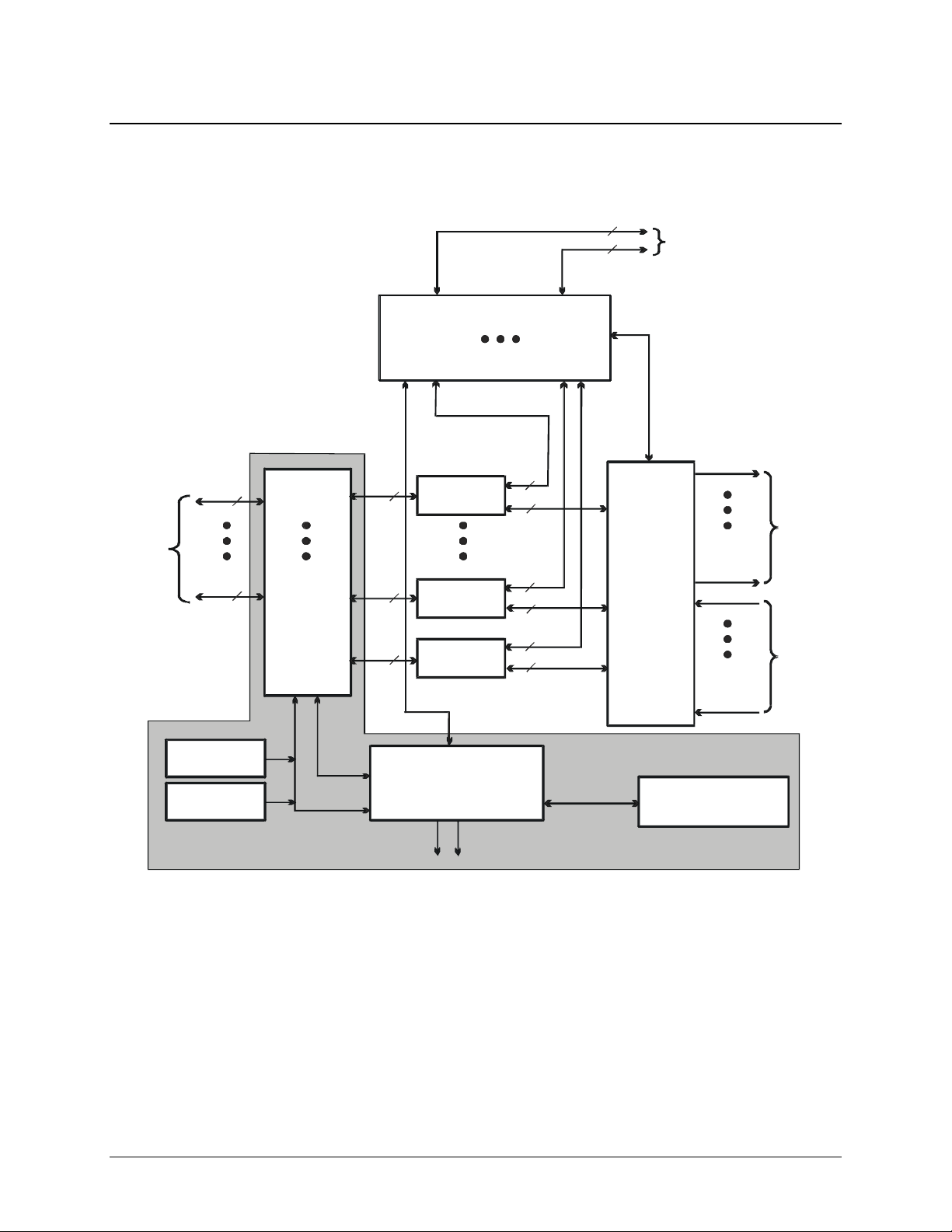
CRS-300 1:10 Redundancy Switch Revision 16
y
y
r
y
r
Introduction MN/CRS300.IOM
1.3 System-Level Block Diagram
Figure 1-1 shows the system-level block diagram of the CRS-300 1:10 Redundancy Switch,
including the optional CRS-280/280L IF and CRS-350 ESC Switches.
CRS-350 ESC Switch
(Optional)
TMI
#1
TMI
#10
3
3
Control
RMI
User Alarms,
Audio,
Overhead
1 or 2
Use
Terrestrial
Data
1 or 2
CRS-240
Power Suppl
CRS-240
Power Suppl
CRS-300 Data Switch
Figure 1-1. Typical Redundancy System-Level Block Diagram
TMI #1
TMI #10
RMI
RMI Interface
1 or 2
1 or 2
1 or 2
Control
System Controlle
User EIA-232/485 M&C
Modem # 1
Modem # 10
Modem #11
CRS-230
System Alarms
3
2
CRS-280/280L
IF Switch
(Optional)
See Fig. 1-2
for schematic
To Up
Converters
3
2
3
2
CRS-300
Front Panel Keypad,
LCD and LED Displa
From Down
Converters
1–5
Page 28
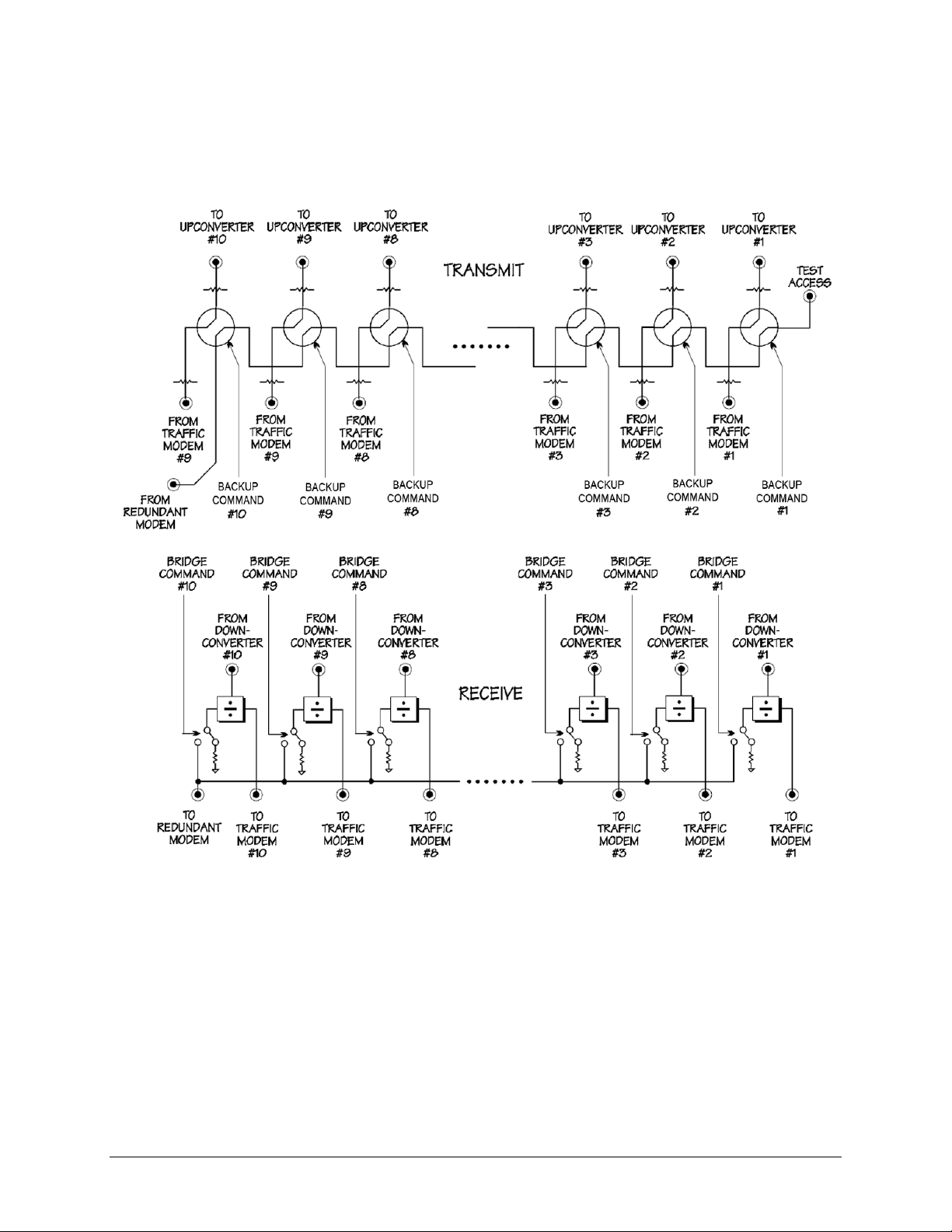
CRS-300 1:10 Redundancy Switch Revision 16
Introduction MN/CRS300.IOM
1.3.1 CRS-280/280L Functional Schematic
Figure 1-2 provides an operational schematic for the CRS-280/280L IF Switch.
Figure 1-2. CRS-280/280L IF Switch Operational Schematic
1–6
Page 29
CRS-300 1:10 Redundancy Switch Revision 16
Introduction MN/CRS300.IOM
1.4 Description of CRS-300 Features
1.4.1 Front Panel
Figure 1-3 illustrates the CRS-300 front panel. The CRS-300 is constructed as a 4RU-high, rackmounting chassis that can be freestanding, if desired. It is provided with rack handles at the front for
easy removal from and placement into a rack.
LED Vacuum Fluorescent
Indicators Keypad Display (VFD)
Figure 1-3. CRS-300 Front Panel
1–7
Page 30
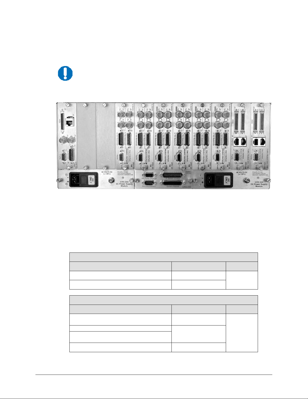
CRS-300 1:10 Redundancy Switch Revision 16
Not
2
Not
2
Introduction MN/CRS300.IOM
1.4.2 Rear Panel
Figure 1-4 shows the back panel of the CRS-300 with a typically configured mix of TMI cards.
Because the RMI can have the capability for several TMIs, depending on user
requirements the CRS-300 may be able to use several different TMI cards
NOTE
CRS-306
simultaneously.
(2X) Unused
RMI
Blanks
CRS-250
Power Supply Module
Figure 1-4. CRS-300 Rear Panel – Configuration Example
(6X) CRS-325
TMI
CRS-230
System Controller
(2X) CRS-336
TMI
CRS-250
Power Supply Module
1.4.3 Modem Interface Cards: CDM-570/570L, -600/600L, -625
The following tables indicate which TMI (Traffic Modem Interface) cards and which RMI
(Redundant Modem Interface) cards should be used with each modem and data type:
CDM-570/570L Modems
Data Type TMI Type RMI Type
G.703 T1/E1 Bal/Unbal CRS-330 or CRS-340
EIA-422, V.35, EIA-232 CRS-340
CDM-600/600L Modems, CDM-625 Modem (in CDM-600 Emulator Mode)
Data Type TMI Type RMI Type
G.703 Bal (DDI, IDO, DDO, IDI)
G.703 Unbal (DDI, IDO, DDO, IDI)
EIA-422/V.35, EIA-232, LVDS
G.703 Bal (DDI, IDO, DDO, IDI)
G.703 Unbal
Converts LVDS (Modem) to/from HSSI (User) CRS-370
Notes 1, 2
es 1,
Notes 1, 2
es 1,
CRS-330
CRS-340
Note 3
CRS-310
CRS-310
1–8
Page 31

CRS-300 1:10 Redundancy Switch Revision 16
Note 4
Not
Note2
Note2
Note2
Introduction MN/CRS300.IOM
CDM-625 Modem
Data Type TMI Type RMI Type
EIA-422, V.35
10/100 Ethernet
es 5, 6
ASI
G.703 Bal (DDI, IDO, DDO, IDI)
G.703 Unbal
G.703 Bal (DDI, IDO, DDO, IDI)
G.703 Unbal (DDI, IDO, DDO, IDI)
HSSI
10/100 Ethernet
EIA-422, V.35, LVDS
G.703 Bal (DDI, IDO, DDO, IDI)
G.703 Unbal
Quad E1
Note 2
Notes 1, 2
Note 4
Note 2
CRS-316
CRS-325
CRS-330
CRS-336
CRS-340
CDS-365D
Notes 5, 6
Notes 5, 6
Notes 5, 6
Note 3
Notes 5, 6
CRS-310
Notes:
1. For CDM-600 modem to switch data (Bal and Unbal) use DB-15 to DB-15
data cable.
2. For CDM-625 modem to switch data (Bal and Unbal) use DB-9 to DB-15
data cable.
3. As of September 2008, the CRS-320 TMI is obsolete. Use the CRS-340
TMI in its place.
4. For CDM-625 where the terrestrial data type is Ethernet, the User can use
only one of any four Ethernet ports on the CDM-625 rear panel in Ethernet
Bridge Mode.
5. From Redundant Modem to RMI, use DB-25 to DB-25 Control cable.
6. From Traffic Modem to TMI, use DB-9 to HD-15 Control cable.
1.4.3.1 RMI Card: CDM-570/570L, -600/600L, -625
Figure 1-5.
CRS-310 RMI
(PL/9579-1)
(2X) BNC - Male DB-15 Male
HD-50 Female DB-25 Male
1–9
Page 32

CRS-300 1:10 Redundancy Switch Revision 16
Introduction MN/CRS300.IOM
1.4.3.2 TMI Cards: CDM-570/570L, -600/600L, -625
Figure 1-6.
CRS-320 TMI EIA-
232/-422 (PL/9581-1)
OBSOLETE
REPLACED BY
CRS-340
Figure 1-7.
CRS-330 TMI
G.703
(PL/9033-1)
DB-25 Female DB-25 Male
DB-15 Male DB-25 Male RJ-45
DB-15 Female (4X) BNC - Female
DB-15 Male DB-25 Male
Figure 1-8.
CRS-340 TMI EIA-
232/-422 or LVDS
or G.703
(PL/9387-1)
Figure 1-9.
CRS-365D TMI E1
(1-4 ports)
(PL/12985-2)
FOR USE WITH
CDM-625 ONLY
Figure 1-10.
CRS-370 TMI
HSSI (PL/9034-1)
FOR USE WITH
CDM-600 ONLY
(2X) BNC - Male DB-15 Female DB-25 Female
DB-9 Female DB-9 Female
DB-9 Male DB-9 Male HD-15 Female
HD-50 Female DB-25 Male
Depending on the traffic data type, the appr op riat e jump er se tti n gs are pr ovi d ed on
the TMI to ensure proper operation for RTS/CTS, DTR/DSR (CRS-320 (obsolete) or
MPORTANT
1–10
CRS-340 TMIs) and CA/TA (CRS-370 TMI). Refer to Chapter 4. MODEM, TMI AND
SWITCH CONFIGURATION for this important configuration informa tion.
Page 33

CRS-300 1:10 Redundancy Switch Revision 16
Note 1
Note 2
Note 3
Note 3
Not
4
Introduction MN/CRS300.IOM
1.4.4 Modem Interface Cards: CDM-Qx/QxL, -700, -710, -710G,
SLM-5650/5650A
The following tables indicate the TMI (Traffic Modem Interface) and RMI (Redundant Interface)
cards that should be used with each modem and data type:
CDM-Qx/QxL Modems
Data Type TMI Type RMI Type
EIA-530/-422/V.35, EIA-232
CRS-316
G.703 T1/E1 Bal D&I , Unbal CRS-325
HSSI
CRS-336
Quad E1 CRS-365
CDM-700 Modem
Data Type TMI Type RMI Type
OC3 Copper CRS-325
HSSI or GigE
CRS-336
G.703 (E3/T3/STS-1) UnBal 1 to 4 Ports CRS-345
CDM-710 Modem
Data Type TMI Type RMI Type
ASI CRS-325
HSSI or GigE
CRS-336
CDM-710G Modems
Data Type TMI Type RMI Type
G.703 Unbal CRS-325
HSSI or GigE
CRS-336
SLM-5650/5650A Modems
Data Type TMI Type RMI Type
MIL-STD-188-114, EIA-530/-422 or Single-port
Ethernet Bridge Mode
G.703 Bal/UnBal CRS-325 CRS-306
HSSI or Single-port Ethernet Bridge Mode
CRS-316
CRS-336
Notes 2, 4
Note 4
Note 4
Note 1
es 2,
CRS-305
CRS-306
CRS-306
CRS-306
CRS-306 (GigE only)
CRS-307
CRS-306/307
Notes – As of April 2007:
1. Use CRS-316 instead of CRS-315. To maintain older TMIs in the field, Switch firmware
must also support the CRS-315.
2. Use CRS-336 instead of CRS-335. To maintain older TMIs in the field, Switch firmware must
also support the CRS-335.
3. Use CRS-306 instead of CRS-305. To maintain older RMIs in the field, Switch firmware
must also support the CRS-335.
4. For modems where the terrestrial data type is Ethernet, the User can use only one Ethernet
port in Single-port Ethernet Bridge Mode, on the modem rear panel (when using the optional
Ethernet interface).
1–11
Page 34

CRS-300 1:10 Redundancy Switch Revision 16
Introduction MN/CRS300.IOM
1.4.4.1 RMI Cards: CDM-Qx/QxL, -700, -710, -710G, SLM-5650/5650A
Figure 1-11.
CRS-305 RMI
(PL/11494-1)
Figure 1-12.
CRS-306 RMI
(PL/11494-2)
Figure 1-13.
CRS-307 RMI
(PL/11494-3)
HD-50 Female HD-15 Female
10/100/1000 (2X) BNC Male DB-15 Male
HD-50 Female HD-15 Female
DB-25 Male DB-15 Male
DB-25 Male (2X) BNC Male DB-15 Male
HD-50 Female RJ-45 HD-15 Female
1–12
Page 35
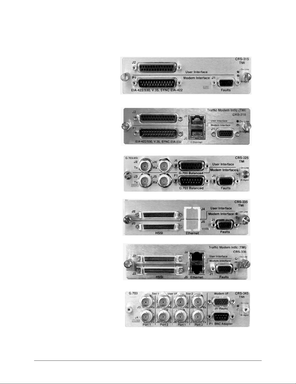
CRS-300 1:10 Redundancy Switch Revision 16
Introduction MN/CRS300.IOM
1.4.4.2 TMI Cards: CDM-Qx/QxL, -700, -710, -710G, SLM-5650/5650A
DB-25 Female
Figure 1-14.
CRS-315 TMI
(PL/11493-1)
OBSOLETE
Figure 1-15.
CRS-316 TMI
RS422 or GigE
(PL/12498-1)
ALSO USED
WITH CDM-625
Figure 1-16.
CRS-325 TMI
G.703 or ASI
(PL/11492-1)
ALSO USED
WITH CDM-625
Figure 1-17.
CRS-335 TMI
(PL/11491-1)
DB-25 Male HD-15 Female
DB-25 Female RJ-45
DB-25 Male RJ-45 HD-15 Female
(2X) BNC Male DB-15 Female
(2X) BNC Male DB-15 Male HD-15 Female
OBSOLETE
(2X) HD-50 Female HD-15 Female
Figure 1-18.
CRS-336 TMI
HSSI or GigE
(PL/12499-1)
ALSO USED
WITH CDM-625
(2X) HD-50 Female (2X) RJ-45 HD-15 Female
HD-15 Female
Figure 1-19.
CRS-345 TMI
G.703 (4 ports)
(PL/11495-1)
FOR USE WITH
CDM-700 ONLY
(8X) BNC Male DB-9 Male
1–13
Page 36

CRS-300 1:10 Redundancy Switch Revision 16
Introduction MN/CRS300.IOM
Figure 1-20.
CRS-365 TMI E1
(1-4 ports)
(PL/12985-1)
FOR USE WITH
CDM-Qx/QxL
ONLY
(4X) RJ-45
(4X) RJ-45 HD-15 Female
1.4.5 CRS-300 System Controller and Power Supply Card Assemblies
DB-9 Female DB-25 Male
Figure 1-21.
CRS-230
System
Controller
(AS/0377)
DB-9 Male DB-25 Female
Figure 1-22.
CRS-240 AC
Power Supply
(AS/0376)
Figure 1-23.
CRS-250 DC
Power Supply
(PL/10458-1)
1.5 CRS-350 ESC Switch Description
The CRS-350 is intended for use with the CDM-600/600L, CDM-625, and SLM-5650/5650A
modems. The CRS-350 is constructed as a 3RU-high, rack-mounting chassis designed for
mounting to the back of a 19-inch rack. See Figure 2-1 in
installation example.
Figure 1-24
shows the user interface si
to the Audio, Overhead, and IRD connector interfaces featured on the CRS-355 User Data
Interface (UDI).
1–14
de of the CRS-350 ESC Switch. Here, the User has access
Chapter 2. INSTALLATION for an
Page 37
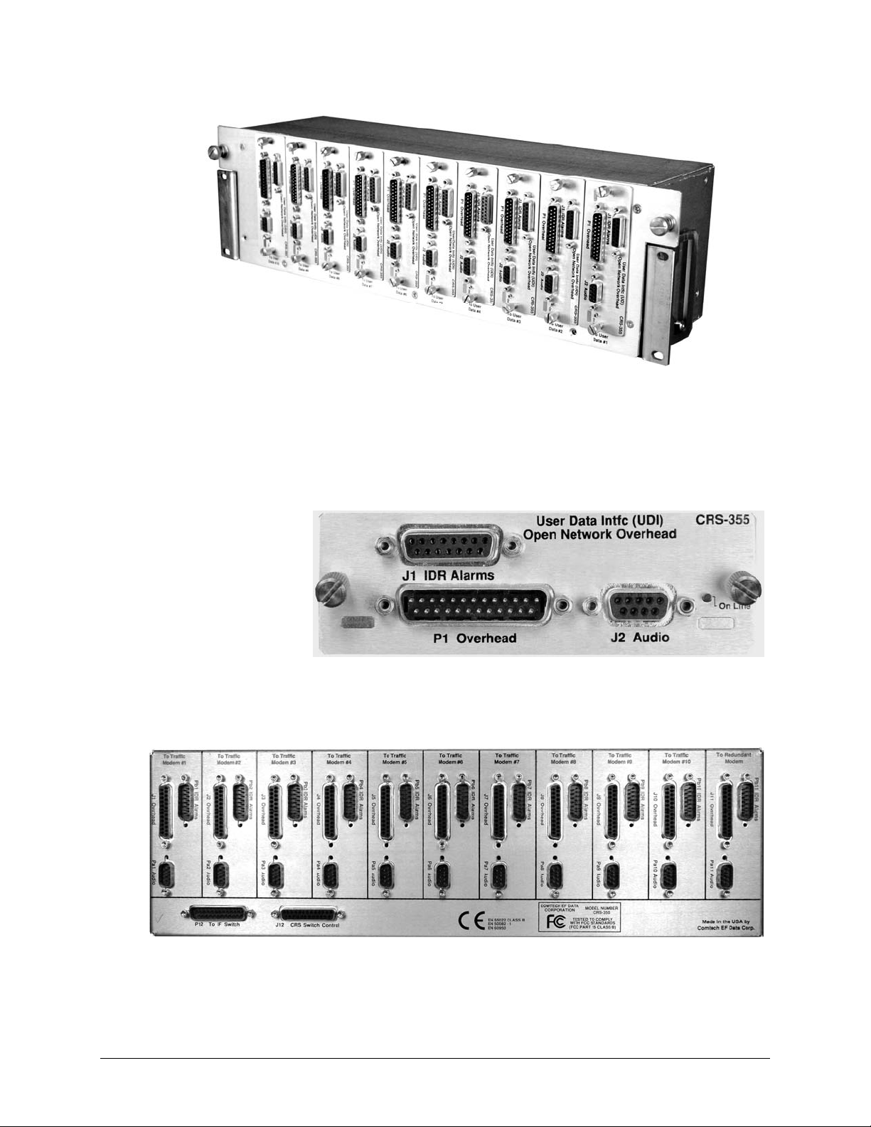
CRS-300 1:10 Redundancy Switch Revision 16
Introduction MN/CRS300.IOM
Figure 1-24. CRS-350 ESC Switch – Front Panel
As explained in detail in the pertinent modem sections of
Chapter 5. CABLES AND CONNECTIONS,
the User’s equipment should be connected directly to the ports on the UDI instead of connecting directly
to the Traffic Modem’s “Audio”, “Overhead”, and “IDR Alarms” ports. Figure 1-25 shows the ty
pical
front panel for one of the (10) CRS-355 UDIs installed on the front panel of the CRS-350 ESC Switch.
DB-15 Female
Figure 1-25.
CRS-355 UDI
DB-25 Male DB-9 Female
The back of the CRS-350, shown in Figure 1-26, contains the same three connectors that correlate
with their respective connectors on each of the modems.
Figure 1-26. CRS-350 ESC Switch – Rear Panel
1–15
Page 38

CRS-300 1:10 Redundancy Switch Revision 16
Introduction MN/CRS300.IOM
1.6 Summary of Specifications
1.6.1 CRS-300 Specifications
Characteristic Requirement
Switch Type
Compatible Modems
Operating Modes
Switching Conditions Switch to redundant modem following a Unit fault, Tx or Rx traffic faults
Switching Time 9 seconds max. (Delay interval set to minimum, 1 sec)
IF Switching
Temperature
Humidity 95% at +40°C (104°F), Non-condensing
CE Mark EMC and Safety
Environmental
AC Prime Power Two independent inputs: 100 to 250 VAC, 50/60 Hz, at 25 watts VA max
1:N Redundancy Switch system ( N=10 max), Bridging architecture
C161 control processor
• CDM-570/570L
• CDM-600/600L
• CDM-625
• CDM-Qx/QxL
• CDM-700
• CDM-710
• CDM-710G
• SLM-5650/5650A
• Fully automatic or manual
• Force traffic modem to redundant modem
• Remove selected traffic modem from control
• Programmable holdoff-to-backup and holdoff-to -restore (from 1 to 99 seconds)
• CRS-300 without CRS-280/280L IF Switch: IF ON / OFF control through the
Switch controller.
• CRS-300 with CRS-280/280L: all modems outputs ON all the time.
• 0 to +50°C (32 to 122°F) Operating
• 50 to 100°C (122 to 212°F) Storage
Operating temperature range: 0° to 40°C (32° to 104°F)
DC Prime Power 48 (38 to 60) VDC 25 watts max
Redundant Modem
Signal Source
Any one of the 10 traffic paths (bridge mode) (both Rx IF and Tx data)
• Vacuum Fluorescent Display (VFD): 2 lines @ 24 characters/line.
• 6-button Keypad: ENT (Enter), CLR (Clear), (4X) navigation
Front Panel
• LED system status display showing, for all modems:
o Unit fault, Rx traffic fault
o Tx traffic alarm Online / Offline status
o Bridge status
Audible Alarm Programmable to activate following various changes of state
Common faults Dry relay contacts
Dimensional Envelope 19W x 11.75D x 6.75H inch (48.26W x 29.85D x 17.15H cm) (4RU)
Weight ~ 20 lbs (~ 9.07 kg)
1–16
Page 39

CRS-300 1:10 Redundancy Switch Revision 16
Introduction MN/CRS300.IOM
1.6.2 Modem vs. Terrestrial User Data Interface S pecifications
Modem TMI User Data Type
CDM-570
CDM-570L
CDM-600
CDM-600L
CDM-625
CDM-Qx
CDM-QxL
CDM-700
CDM-710
CDM-710G
SLM-5650/5650A
CRS-330 G.703 (Balanced/Unbalanced) (1) DB-15F/ (2) BNC
CRS-340
CRS-330
CRS-340
CRS-370 HSSI (User) (1)HD-50F
CRS-316
CRS-325
CRS-330
CRS-336
CRS-340
CRS-365D Quad E1 (1 to 4 Ports of E1) (2) DB-9F
CRS-316 EIA-530, V.35, EIA-232 (1) DB-25F
CRS-325
CRS-336 HSSI (1) HD-50F
CRS-365 Quad E1 (1 to 4 Ports of E1) (4) RJ45s
CRS-325 OC3 Copper (2) BNCs
CRS-336
CRS-345 Multi-Port Unbal G.703 (1-4 ports) (8) BNCs
CRS-325 ASI (2) BNCs
CRS-336
CRS-325 G.703 Unbal (2) BNCs
CRS-336
CRS-316
CRS-325
CRS-336
EIA-422, V.35, EIA-232 (1) DB-25F
G.703 (Balanced/Unbalanced) (1) DB-15F/ (2) BNC
G.703 Bal (DDI,IDO, DDO, IDI)
G.703 Unbal (DDI, IDO, DDO, IDI)
EIA-422, V.35,EIA-232, LVDS (1) DB-25F
G.703 Bal (DDI,IDO, DDO, IDI)
G.703 Unbal (DDI, IDO)
EIA-422, V.35 (1) DB-25F
Single-port Ethernet Bridge Mode (1) RJ45
ASI (2) BNCs
G.703 Bal (DDI,IDO, DDO, IDI)
G.703 Unbal (DDI, IDO)
G.703 Bal (DDI,IDO, DDO, IDI)
G.703 Unbal (DDI, IDO, DDO, IDI)
HSSI (1) HD-50F
Single-port Ethernet Bridge Mode (1) RJ45
EIA-422, V.35, LVDS (1) DB-25F
G.703 Bal (DDI,IDO, DDO, IDI)
G.703 Unbal (DDI, IDO)
G.703 Bal (DDI,IDO, DDO, IDI)
G.703 Unbal (DDI, IDO)
HSSI (1) HD-50F
GigE (one port only) (1) RJ45
HSSI (1) HD-50F
GigE (one port only) (1) RJ45
HSSI (1) HD-50F
GigE (one port only) (1) RJ45
MIL-STD-188-114, EIA-530 (1) DB-25F
GigE (1) RJ45
G.703 Bal (DDI,IDO, DDO, IDI)
G.703 Unbal (DDI, IDO)
HSSI (1) HD-50F
Single-port Ethernet Bridge Mode (1) RJ45
User Data
Connector(s)
(1) DB-15F
(4) BNCs
(1) DB-15F
(2) BNCs
(1) DB-15F
(2) BNCs
(1) DB-15F
(4) BNCs
(1) DB-15F
(2) BNCs
(1) DB-15F
(2) BNCs
(1) DB-15F
(2) BNCs
1–17
Page 40

CRS-300 1:10 Redundancy Switch Revision 16
Introduction MN/CRS300.IOM
1.6.3 CRS-280 and CRS-280L Specifications
Characteristic
CRS-280 (70/140MHz) CRS-280L (L-Band)
Tx/Rx Operating Freq 50 to 180 MHz 950 to 1950 MHz
Requirement
Tx / Rx Connectors BNC female
Return Loss
Transmit IF Loss/Flatness
Tx In To Tx Uplink Out
BU In To Any Uplink Out
Receive IF Loss/Flatness
Rx Downlink In To Rx Out
Any Downlink In To BU Out
Tx to Tx Channel Isolation > 50 dB > 70 dB
Rx to Rx Channel Isolation > 50 dB > 70 dB
Tx to Rx Channel Isolation > 60 dB > 90 dB
Powering of IF Switch From the CRS-300 chassis 100 to 240 VAC 50/60 Hz (25W)
Power Supply 90-264 VAC, 50/60 Hz (25 W) 90-264 VAC
Fuse
Dimensional Envelope
(Rack Mount 4RU)
Weight < 10 lbs (< 4.54 kg) < 25 lbs (11.3 kg)
18 dB return loss into 75Ω
(50Ω optional)
-< 1.5 dB over operating freq
< 1.5 dB over operating freq
-< 5 dB over operating freq
< 5 dB over operating freq
19W x 2.5D x 7H inches (48.26W x 6.35 x 18H cm)
N-Type female (50Ω)
15 dB return loss into 50Ω
-< 0.8 dB/0.5 dB over operating freq
< 2.5 dB/1.0 dB over operating freq
-< 4.0 dB/0.5 dB over operating freq
< 5.5 dB/1.0 dB over operating freq
1.6.4 CRS-350 Specifications
Characteristic Requirement
User Data Interfaces (1) 25-pin 'D' male connector - ESC, overhead signals
(1) 15-pin 'D' female connector - IDR Alarms
(1) 9-pin ‘D’ female connectors - Audio
Power From CRS-300
Dimensional Envelope
(Rack Mount 4U)
Weight 5 lbs (2.2 kg)
1–18
19W x 4.0D x 7H inches
(48.26W x 27.5D x 18H cm)
Page 41

CRS-300 1:10 Redundancy Switch Revision 16
A
Introduction MN/CRS300.IOM
1.6.5 Dimensional Envelopes
17.00
(43.2)
11.94
(30.3)
UNIT STATUS
CRS-300
REDUNDANCY SWITCH
STORED EVENT
REMOTE
TRANSMIT PROMPT
RECEIVE PROMPT
DEFERRED
ON LINE
BRIDGED
TRAFFIC MODE M 1 2 3 4 5 6 7 8 9 10
ENT
18.25
(463.5)
COMTECH CRS-300 SWITCH
S/N 021459243 S W V E R 1.01
CLR
UNIT STATUSUNIT STATUS
TRANSMIT TRAFFIC
RECEIVE TRAFFIC
DEFERRED
ON LINE
NT
REDUND
MODEM
19.00
(482.6)
5.24
(133.1)
.86 (22)
6.97
(177)
12.68
(322)
Figure 1-27. CRS-300 Dimensional Envelope
Figure 1-28. CRS-350 Dimensional Envelope
1–19
Page 42
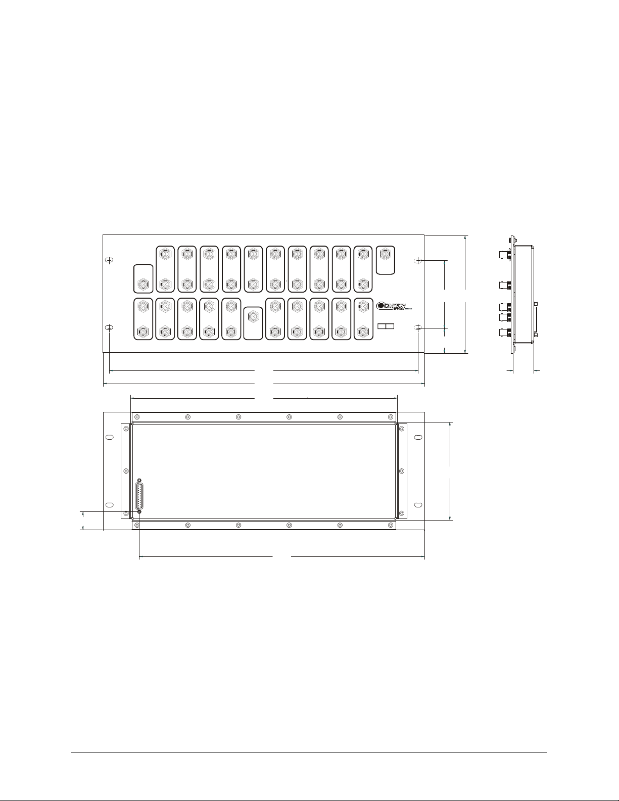
CRS-300 1:10 Redundancy Switch Revision 16
Introduction MN/CRS300.IOM
1.073
(2.7)
Tx 1 Tx 2 Tx 3
TO UP
TO UP
CONVERTER
FROM DOWN
CONVERTER
TO TRAFFIC
TO UP
CONVERTER
FROM
FROM
TRAFFIC
TRAFFIC
MODEM
MODEM
FROM DOWN
CONVERTER
TO TRAFFIC
MODEM
MODEM
CONVERTER
Tx
FROM
FROM
TRAFFIC
REDUNDANT
MODEM
MODEM
FROM DOWN
FROM DOWN
CONVERTER
CONVERTER
TO TRAFFIC
TO TRAFFIC
MODEM
MODEM
Rx 1Rx 2Rx 3Rx 4
CONVERTER
TRAFFIC
MODEM
FROM DOWN
CONVERTER
TO TRAFFIC
MODEM
Tx 6Tx 5Tx 4 Tx 7 Tx 8
TO UP
TO UP
TO UP
CONVERTER
FROM
FROM
TRAFFIC
MODEM
TO
REDUNDANT
MODEM
Rx
18.260
(46)
19.000
(48)
15.800
(40)
TO UP
CONVERTER
CONVERTER
FROM
FROM
TRAFFIC
TRAFFIC
MODEM
MODEM
FROM DOWN
FROM DOWN
CONVERTER
CONVERTER
TO TRAFFIC
TO TRAFFIC
MODEM
MODEM
Rx 6Rx 5 Rx 7 Rx 8
CONVERTER
FROM DOWN
CONVERTER
TO TRAFFIC
Tx 9 Tx 10
TO UP
TO UP
TO UP
CONVERTER
TRAFFIC
MODEM
FROM DOWN
CONVERTER
TO TRAFFIC
MODEM
TEST POINT
FROM
6.960
4.000
(17.7)
(10)
CRS-280
IF SWITCH
50 75 OHMS
1.480
(3.8)
1.229
(3.1)
5.800
(14.7)
CONVERTER
FROM
FROM
TRAFFIC
TRAFFIC
MODEM
MODEM
FROM DOWN
CONVERTER
TO TRAFFIC
MODEM
MODEM
Rx 9 Rx 10
16.869
(42.8)
Figure 1-29. CRS-280 (70/140 MHz) Dimensional Envelope
1–20
Page 43
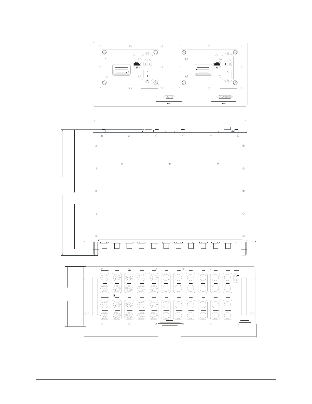
CRS-300 1:10 Redundancy Switch Revision 16
Introduction MN/CRS300.IOM
17.00
(43.18)
13.92
(35.36)
6.96
(17.68)
13.18
(33.48)
Figure 1-30. CRS-280L (L-Band) Dimensional Envelope
1–21
19.00
(48.26)
Page 44

CRS-300 1:10 Redundancy Switch Revision 16
Introduction MN/CRS300.IOM
Notes:
1–22
Page 45

Chapter 2. INSTALLATION
T
2.1 Unpacking and Inspection
Step Procedure
1
2
3
4
5
6
7
IMPORTAN
Inspect shipping containers for damage.
If shipping containers are damaged, keep them until the contents of the
shipment have been carefully inspected and checked for normal operation.
Remove the packing list from the outside of the shipping carton.
Open the carton and remove the contents.
Check the contents against the packing list to verify completeness of the
shipment.
If damage is evident, contact the carrier and Comtech EF Data immediately
and submit a damage report.
If the unit needs to be returned to Comtech EF Data, use the original
shipping container.
Be sure to keep all shipping materials for the carrier's inspection.
2.2 Rack Mounting
The CRS-300 is constructed as a 4RU-high, rack-mounting chassis. Handles are provided to
facilitate removal and placement into a rack.
Mount the Switch in the rack using the mounting holes on the front panel. Use the front panel
screw holes only.
Comtech EF Data if there are questions about rack supports.
Figure 2-1 provides a “cut-away” side view of a ty
with the CRS-300, CRS-280, and CRS-350. The CRS-280 IF Switch can be mounted on the back
DO NOT install rack slides to the side of the CRS-300 chassis – contact
pical rack configuration for modems combined
2–1
Page 46
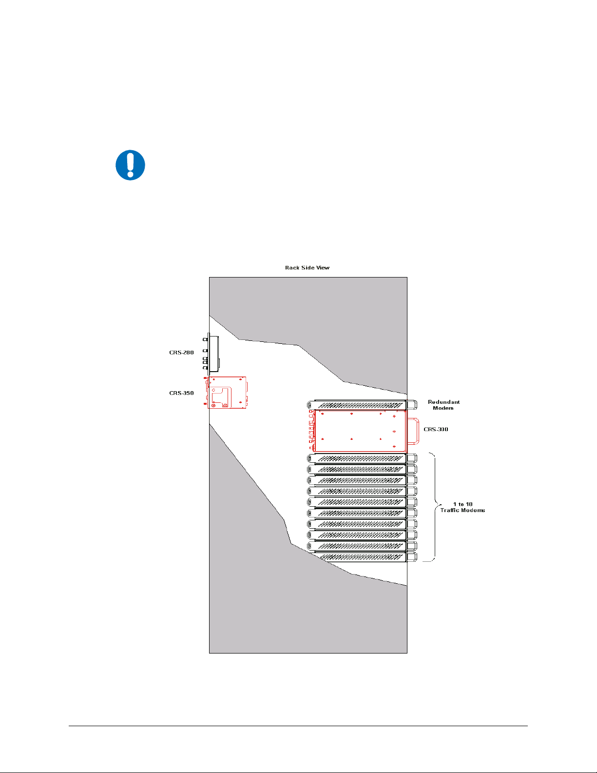
CRS-300 1:10 Redundancy Switch Revision 16
Installation MN/CRS300.IOM
or on top of the rack. If using the CRS-280L, refer also to the associated CRS-280L 1:N
Redundancy Switch Installation and Operation Manual (MN/CRS280L.IOM) for further rack
mounting information. The CRS-350 mounts to the back of the rack. The mounting hardware
allows the user to hinge the unit down to access the data cables in the rear of the unit to connect
the cables to the modems. Mount all Switches and modems in the rack as necessary.
Do not allow the internal rack temperature to exceed 50°C (122° F).
IMPORTANT
It is important to ensure that there is adequate clearance for ventilation in the rack. Since the
Switch itself is relatively passive, no additional clearance is needed between it and the nearest
modem. In rack systems where there is high heat dissipation, provide forced-air cooling by
installing top- or bottom-mounted fans or blowers.
Figure 2-1. Typical Rack Mounting Configuration
2–2
Page 47

Chapter 3. ETHERNET NETWORK
CONFIGURATIONS
3.1 Introduction
For operations requiring Ethernet-based terrestrial data handling, it is important to emphasize the
need for Users to avoid Ethernet looping connection problems – with or without use of the
CRS-300 1:10 Redundancy Switch.
The intent of this chapter is to outline the differing methods for Ethernet-based data handling with
the various modems featured throughout this manual. Additionally, this chapter outlines use of
the CDM-700 Satellite Modem in redundancy. The CDM-700 provides the added functionality of
multiple data type handling simultaneously with Ethernet; i.e., Ethernet & HSSI, Ethernet &
G.703, etc.
3.2 Ethernet Routers vs. Switches
Routers and switches allow connection of one or more computers or networked devices to other
computers or network devices. Each has two or more connectors, called ports, in which cables
connect to other network devices.
An Ethernet switch examines the traffic that comes across it, and learns where particular MAC
addresses are. An Ethernet switch maintains what is known as a CAM (Content Addressable
Memory) table, listing the MAC addresses for each switch port. The Ethernet s witch uses the CA M
table to determine where to forward Ethernet frames. By default, Ethernet switch es will update the
CAM table automatically; for example, i f an Ethernet switch s ees traffic from ‘M achine A’ comin g
in on ‘Port 2’, it now knows that ‘Machine A’ is connected to that port, and that traffic destined for
‘Machine A’ needs to only be sent to that port and not any of the others.
An Ethernet router determines where to forward IP traffic based upon the destination IP address
and the Route table entries in the router. An Ethernet router can be programmed to understand and
route the data it is directed to handl e; for example, broadband routers include the abil ity to "hide"
computers behind a type of firewall, which involves slightly modifying the packets of network
traffic as they traverse the device. All routers in clude some kind of user interface for configuring
how the router will treat traffic: larger routers include the equivalent of a full-blown programming
language to describe how they should operate, as well as the ability to communicate with other
routers to descri be or d et erm ine the bes t wa y to direct network traffic from ‘Point A’ to ‘Point B’.
3–1
Page 48

CRS-300 1:10 Redundancy Switch Revision 16
Ethernet Network Configurations MN/CRS300.IOM
3.3 Ethernet Configuration Examples
This section explains the problems with Ethernet Networking Loo ps, and how to properly design
applications architecture for handling Standard traffic and Split-path traffic. Standard traffic is
defined as Rx and Tx Ethernet traffic using the same port on the same router or switch, whereas
split-path traffic is Rx and Tx Ethernet traffic using different ports of the same router or switch.
Each application also has CRS-300 Redundancy applications examples, with subsequent sections in
this chapter providing examples of applications architecture designed to handle near-to-far end
Ethernet network configurations. This includes:
• Sect. 3.3.3 Hub-to-Hub with Standard Traffic using Switches
• Sect. 3.3.4 Hub-to-Hub with Standard Traffic using Routers
• Sect. 3.3.5 Hub-to-Remotes with Standard Traffic using Routers or Switches
• Sect. 3.3.6 Hub-to-Remotes, Split-path Traffic using Routers (Point-to-Multipoint)
• Sect. 3.3.7 Hub-to-Remotes, Split-path Traffic using Switches (Point-to-Multipoint)
3.3.1 Ethernet Network Overview
When placing modems in a network, there are a number of issues that must be addressed – first
and foremost on the list of concerns is whether implementation of the switches in the network
will cause a Networking Loop. This is problematic because a Networking Loop will cause a
Broadcast Storm, which shuts down the network and causes harm to devices in that network.
Figure 3-1. Networking Loop with Switches
Figure 3-1 illustra
‘Switch 1’ will send out an ARP request looking for a particular MAC, then each subsequent switch
passes along that request until ‘Switch 1’ receives it again. At this point, two things could happen:
1. The switch could continue to forward all requests out all ports, creating more and
tes a Networking Loop with switche
more traffic on the network until there is no bandwidth available and the switch
either reboots or locks up.
s. The problem with this configuration is that
2. The switch could sense that the ARP request came back to the switch on a different
port. The switch could then stop forwarding traffic out the proper port.
Other factors will affect the network: e.g., if the switch is running Spanning Tree Protocol,
VLANs, etc.
3–2
Page 49

CRS-300 1:10 Redundancy Switch Revision 16
Ethernet Network Configurations MN/CRS300.IOM
3.3.2 Ethernet Redundancy with CRS-300
After the customer has determined the best configuration for near-to-far end Ethernet networks,
the CRS-300 1:10 Redundancy Switch may now be added to one or both ends of the link(s).
Ethernet redundancy using the CRS-300 can be accomplished using a wired-thru or
wired-around configuration.
3.3.2.1 Wired-thru Connection
This redundancy approach is the recommended and preferred
MPORTANT
The wired-thru Ethernet connection on the CRS-300 is the easiest and simplest choice for Ethernet
redundancy. This connection method – the same as used on the standard serial data interface –
provides a single connection for the User Data Interface and provides simple form-C relays that
route the Ethernet connection from the User connection to either the Traffic or Redundant Modem.
connection method.
3.3.2.2 Wired-around Connection
While this redundancy approach is not recommended, it can be used
MPORTANT
The wired-around Ethernet connection is used with the CRS-300 and the CDM-700 modem
where both modem data interface slots are needed; e.g., where one slot is HSSI or G.703 and the
other slot is GigE. With the Ethernet slot configured for the wired-around method, this gives full
redundancy capability to both data slots. However, care must be taken to ensure there are no
Ethernet network loops or connection problems – this method should only be used if both modem
data slots are used. In general, the wired-around approach can be used in a hub-to-remotes
configuration with standard traffic.
after study of the LAN and WAN sides of the IP networks.
3–3
Page 50

CRS-300 1:10 Redundancy Switch Revision 16
Ethernet Network Configurations MN/CRS300.IOM
3.3.3 Hub-to-Hub with Sta ndard Traffic using Switches
When connecting two or more “hub-sites” where there are multi-paths between each site, care must
be taken to ensure no network loops occur. Figure 3-2
depicts two hub-sites conn
more modems where all the traffic being transmitted and received is on the same LAN/VLAN.
Figure 3-3 shows a simplified version of the Networ
king Loop. Since there is no router in the
network and all the traffic is destined to the same network, routing loops have been created.
As illustrated, two switches have been connected, each with two or more separate connections.
This is not how the Ethernet switches were designed to be used, and this configuration will cause
a network outage.
ected with two or
Figure 3-2. Networking Loop Example
Figure 3-3. Networking Loop Example (Simplified)
3–4
Page 51

CRS-300 1:10 Redundancy Switch Revision 16
Ethernet Network Configurations MN/CRS300.IOM
This page is intentionally blank.
3–5
Page 52
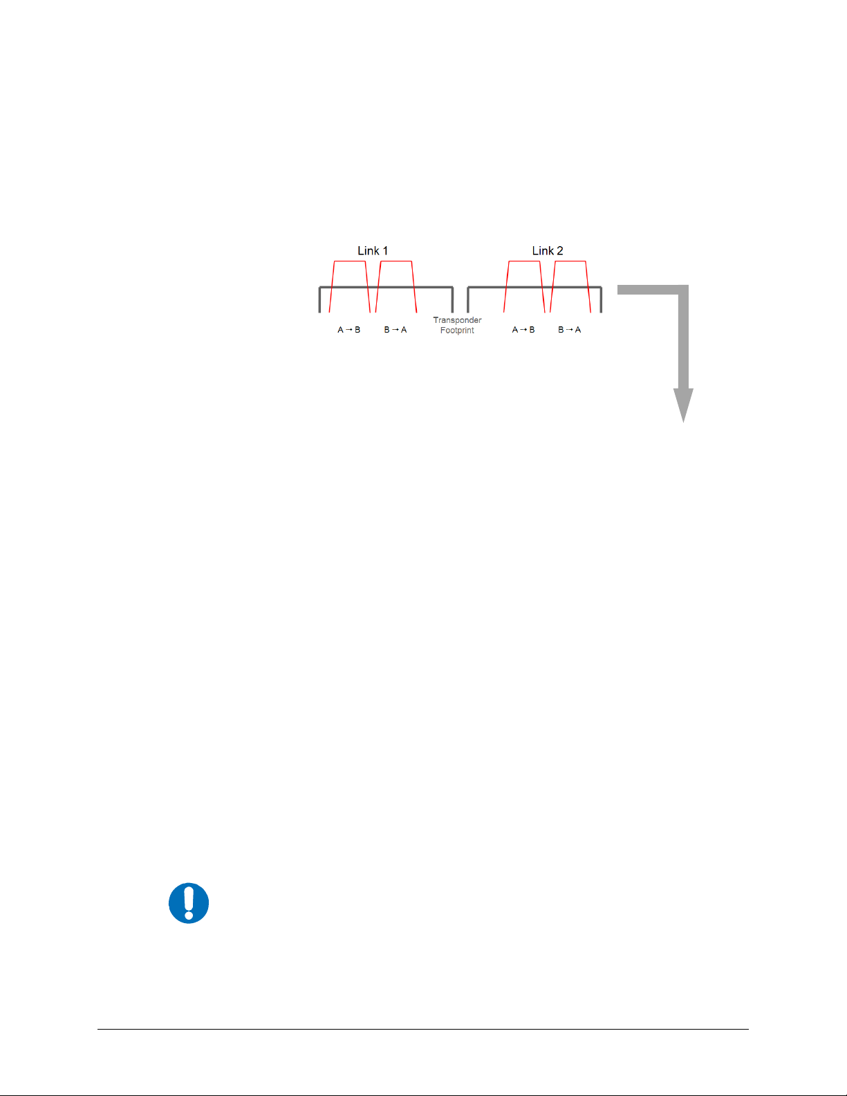
CRS-300 1:10 Redundancy Switch Revision 16
Ethernet Network Configurations MN/CRS300.IOM
3.3.4 Hub-to-Hub with Standard Traffic using Routers
Figure 3-4 shows two hub-sites connected with standard Ethernet traffic, using routers instead of
switches for Ethernet connection. The routers will block the broadcasts coming from the remote
network. Therefore, no broadcast storm can be created or the possibility of having a remote MAC
on the Hub networks.
Figure 3-4. Hub-to-Hub with Standard Traffic using Routers
A wired-thru Ethernet redundancy example is shown in Figure 3-5. When
Redundancy Switch “backs-up” a faulted Traffic Modem, the physical port on the router does not
change, because the Ethernet connection is properly rerouted within the CRS-300 from the
Traffic Modem to the Redundant Modem.
A wired-around Ethernet redundancy example is shown for the CDM-700 User in Figure 3-6.
When the CRS-300 1
edundancy Switch backs-up a faulted Traffic Modem, the physical port
:10 R
on the router needs to change from the Traffic Modem port to the Redundant Modem port.
Because of this, special router configuration is required for successful operation – the User may
need to consult with the router manufacturer.
The wired-around redundancy approach is not recommended.
MPORTANT
3–6
the CRS-300 1:1
0
Page 53

CRS-300 1:10 Redundancy Switch Revision 16
Ethernet Network Configurations MN/CRS300.IOM
Figure 3-5. Wired-thru for Hub-to-Hub with Standard Traffic using Routers
Figure 3-6. Wired-around for Hub-to-Hub with Standard Traffic using Routers
3–7
Page 54
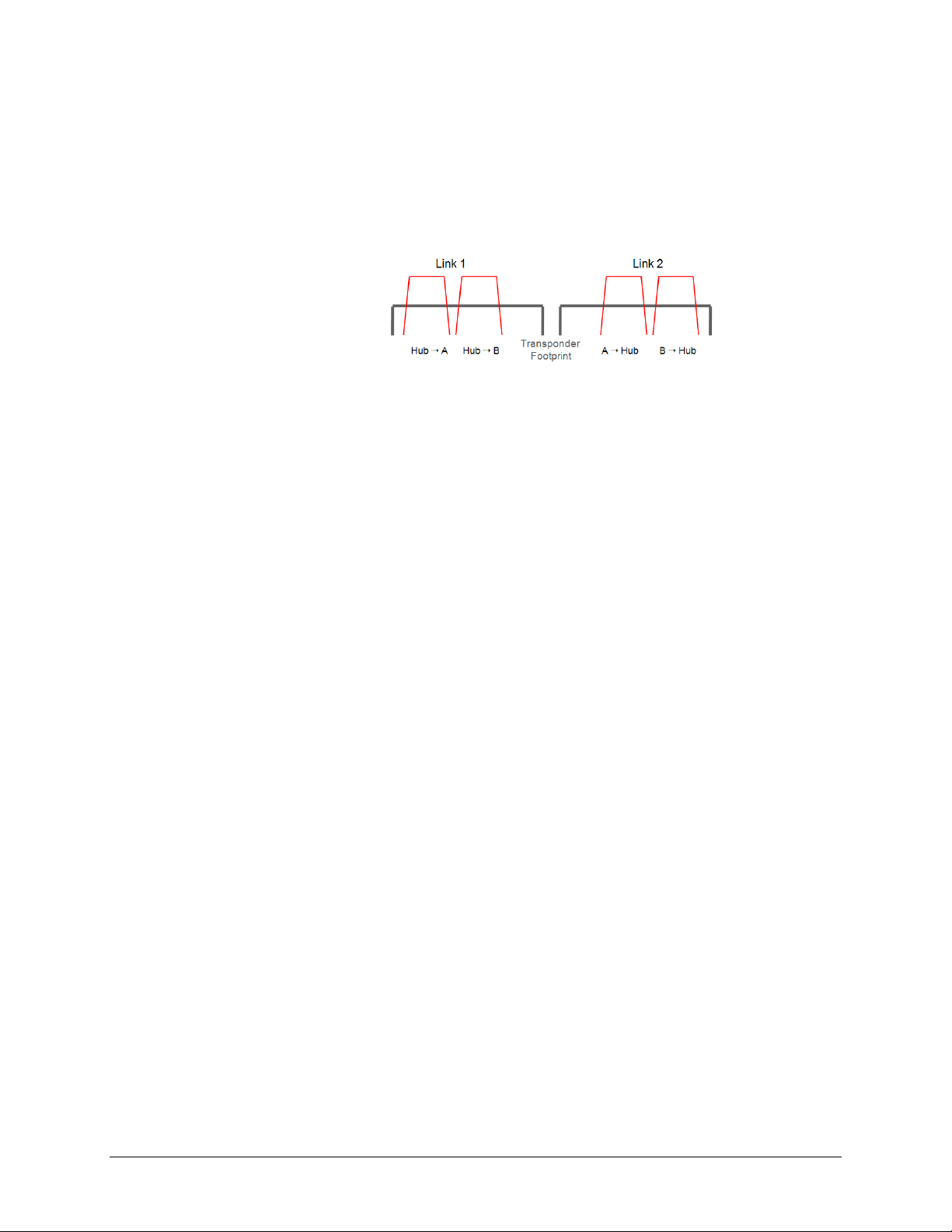
CRS-300 1:10 Redundancy Switch Revision 16
Ethernet Network Configurations MN/CRS300.IOM
3.3.5 Hub-to-Remotes with Standard Traffic using Routers or Switches
Figure 3-7 shows hub-to-remotes configuration with standard Ethernet traffic using routers or
switches. The routers/switches will block broadcasts coming from the hub and remote networks.
Therefore, no broadcast storm can be created or the possibility of having a remote MAC on the
Hub networks.
Figure 3-7. Hub-to-Remotes with Standard Traffic using Routers or Switches
A wired-thru Ethernet redundancy example is shown in Figure 3-8. When
Redundancy Switch backs-up a faulted Traffic Modem, the physical port, (on the router) does not
change because the Ethernet connection is properly rerouted within the CRS-300 from the Traffic
Modem to the Redundant Modem.
A wired-around Ethernet redundancy example for the CDM-700 User is shown Figure 3-9.
Whe
the CRS-300 1:10 Redundancy Switch backs-up a faulted Traffic Modem, the Dwitch
n
will learn the new MAC address of the redundant unit and traffic will be passed again. This
type of architecture will slow down the switching time, because the Switch will need to re-learn
the correct port connection.
3–8
the CRS-300 1:1
0
Page 55

CRS-300 1:10 Redundancy Switch Revision 16
Ethernet Network Configurations MN/CRS300.IOM
Figure 3-8. Wired-thru for Hub-to-Remotes with Standard Traffic using Routers or Switches
Figure 3-9. Wired-around for Hub-to-Remotes with Standard Traffic using Routers or Switches
3–9
Page 56

CRS-300 1:10 Redundancy Switch Revision 16
Ethernet Network Configurations MN/CRS300.IOM
3.3.6 Hub-to-Remotes, S plit-p ath Traffic using Routers (Point-to-Multipoint)
Figure 3-10 shows hub-to-remotes configuration with standard and split-path Ethernet traffic, using
routers. A Static ARP Entry is needed in the switch so that routing of the Tx side of the modems
will be on the correct port of the router. For example, the Rx side of the Eth ernet connection for
‘Traffic Modem #N’ comes in the bottom port of the Router, but th e Tx Ethernet connection must
be connected through the same port as ‘Traffic Modem #1’, as shown in this figure.
Figure 3-10. Point-to-Multipoint using Routers
A wired-thru Ethernet redundancy example is shown in Figure 3-11. W
Redundancy Switch backs-up a faulted Traffic Modem, the physical port on the router does not
change, because the Ethernet connection is properly rerouted within the CRS-300 from the
Traffic Modem to the Redundant Modem.
A wired-around Ethernet redundancy example is shown for the CDM-700 User in Figure 3-12.
When the CRS-300 1
edundancy Switch backs-up a faulted Traffic Modem, the physical port
:10 R
on the router needs to change from the Traffic Modem port to the Redundant Modem port.
Because of this, special router configuration is required for successful operation – the User may
need to consult with the router manufacturer.
The wired-around redundancy approach is not recommended.
MPORTANT
h
en the CRS-300 1:10
3–10
Page 57

CRS-300 1:10 Redundancy Switch Revision 16
Ethernet Network Configurations MN/CRS300.IOM
Figure 3-11. Wired-thru for Point-to-Multipoint with Routers
Figure 3-12. Wired-around for Point-to-Multipoint with Routers
3–11
Page 58

CRS-300 1:10 Redundancy Switch Revision 16
Ethernet Network Configurations MN/CRS300.IOM
3.3.7 Hub-to-Remotes, Split-p ath T raffic using Switches (Point-to-Multipoint)
With switches used, the hub and remote are on the same subnet as shown in Figure 3-13,
meaning that broadcasts will be allowed to transverse the network. Learning Mode must be
disabled on the Hub Tx/Rx modem, because if a computer on the remote sends a broadcast out to
the Hub, the modem learns that MAC is local – when in fact it is not.
Figure 3-13. Point-to-Multipoint using Switches
A wired-thru Ethernet redundancy example is shown in Figure 3-14. W
Redundancy Switch backs-up a faulted Traffic Modem, the physical port on the Switch does not
change, because the Ethernet connection is properly rerouted within the CRS-300 from the
Traffic Modem to the Redundant Modem.
A wired-around Ethernet redundancy example is shown for the CDM-700 User in Figure 3-15.
When the CRS-300 1:1
Redundancy Switch backs-up a faulted Traffic Modem, the Switch will
0
learn the new MAC address of the redundant unit and traffic will be passed again. This type of
architecture will slow down the switching time, because the Switch will need to re-learn the
correct port connection.
3–12
h
en the CRS-300 1:10
Page 59

CRS-300 1:10 Redundancy Switch Revision 16
Ethernet Network Configurations MN/CRS300.IOM
Figure 3-14. Wired-thru, Hub-to-Remotes, Split-path Traffic using Switches
(Point-to-Multipoint)
Figure 3-15. Wired-around, Hub-to-Remotes, Split-path Traffic using Switches
(Point-to-Multipoint)
3–13
Page 60

CRS-300 1:10 Redundancy Switch Revision 16
Ethernet Network Configurations MN/CRS300.IOM
Notes:
3–14
Page 61

CABLES AND CONNECTIONS
T
4.1 Overview
All cables for connecting the CRS-300 1:10 Redundancy Switch to the modems or within the system
are available from Comtech EF Data. These cables can be ordered at the same time the order is placed
for the CRS-300.
If fabricated by the customer, the cables required between each modem and Switch plug-in RMI
or TMI card should be of shielded, twisted-pair construction, with the grounded shield bonded to
the back shell. All data cables should be wired correctly using the pinout and connection
information as specified in
Leave the Switch and all modems powered off until all connections are ready.
IMPORT AN
Once the Switch and all the m odems have been mou nted, the User must properly atta ch all required
cabling. In most cases the modem accepts the m ale end of the cable, while connectors on the RMI or
TMI card accepts the female end of the cable in the section of the card labeled “Modem Interface.”
Refer to the subsections in
on these interfaces. Illustrations featured throughout this chapter provide cabling configuration
examples for RMI or TMI interfaces – i.e., the interconnection of a Redundant Modem to a Switch
RMI card, or the interconnection between a Switch TMI card and a Traffic Modem. The
step-by-step process for connecting a variety of Switch and mod em configur ations is outlin ed in the
following chapter sections:
Chapter 4.
Appendix A. CABLE DRAWINGS.
Chapter 1.4 Description of CRS-300 Features for detailed information
• Sect. 4.2 Switch-to-Switch Connections
• Sect. 4.3 CDM-570/570L Modem Connections
• Sect. 4.4 CDM-600/600L Modem Connections
• Sect. 4.5 CDM-625 Modem Connections
• Sect. 4.6 CDM-Qx/QxL Modem Connections
• Sect. 4.7 CDM-700 Modem Connections
• Sect. 4.8 CDM-710 Modem Connections
• Sect. 4.9 CDM-710G Modem Connections
• Sect. 4.10 SLM-5650/5650A Modem Connections
• Sect. 4.11 IF Cable Connections
4–1
Page 62

CRS-300 1:10 Redundancy Switch Revision 16
Cables and Connections MN/CRS300.IOM
Notes:
4–2
Page 63

CRS-300 1:10 Redundancy Switch Revision 16
Cables and Connections MN/CRS300.IOM
4.2 Switch-to-Switch Connections
o CRS-300 to CRS-280/280L Connection
o CRS-300 to CRS-350 Connection
o CRS-300 to CRS-350 to CRS-280/280L Connection
4–3
Page 64

CRS-300 1:10 Redundancy Switch Revision 16
Cables and Connections MN/CRS300.IOM
4.2 Switch-to-Switch Connections
If the User’s redundancy system requires the Comtech EF Data CRS-280 (70/140 MHz) IF, CRS280L (L-Band) IF, and/or CRS-350 Engineering Service Channel (ESC) Switch (used only with
the CDM-600/600L, CDM-625, or SLM-5650/5650A), Control/Data Cable CA/WR0066 is
needed to connect the Switches. Each CRS-280/280L and CRS-350 is supplied with this cable for
connection to the associated Switch control unit.
The following sections outline the switch-to-switch cable connections between the CRS-300,
CRS-350, and the CRS-280/280L.
4.2.1 CRS-300 to CRS-280/280L Connection
Refer to Figure 4-1 and Figure 4-2 to connect and secure the CA/WR0066 cable between the
CRS-300 and the CRS-280/280L as follows:
• DB-25M connector labeled “IF Switch Control” on the CRS-300’s CRS-230 System
Controller, to
• DB-25F connector on the rear panel of the CRS-280/280L.
4.2.2 CRS-300 to CRS-350 Connection
Refer to Figure 4-3 to connect and secure the CA/WR0066 cable between the CRS-300 and the
CRS-350 as follows:
• DB-25M connector labeled “IF Switch Control” on the CRS-300’s CRS-230 System
Controller, to
• DB-25F connector on the rear panel of the CRS- 350.
4.2.3 CRS-300 to CRS-350 and CRS-280/280L Connection
Refer to Figure 4-4 or Figure 4-5 to first connect and secure the CA/WR0066 cable between the
CRS-300 and CRS-350 as follows:
• DB-25M connector labeled “IF Switch Control” on the CRS-300’s CRS-230 System
Controller, to
• DB-25F connector on the rear panel of the CRS- 350.
Next, connect and secure the second 25-pin CA/WR0066 cable between the CRS-350 and
CRS-280/280L as follows:
• DB-25M connector on the CRS-350, to
• DB-25F connector on the rear panel of the CRS-280/280L.
4–4
Page 65

CRS-300 1:10 Redundancy Switch Revision 16
Cables and Connections MN/CRS300.IOM
Figure 4-1. Control Cable Connection Example for CRS-300 Æ CRS-280
4–5
Page 66
CRS-300 1:10 Redundancy Switch Revision 16
Cables and Connections MN/CRS300.IOM
Figure 4-2. Control Cable Connection Example for CRS-300 ÆCRS-280L
4–6
Page 67
CRS-300 1:10 Redundancy Switch Revision 16
Cables and Connections MN/CRS300.IOM
Figure 4-3. Control Cable Connection Example for CRS-300 Æ CRS-350
4–7
Page 68

CRS-300 1:10 Redundancy Switch Revision 16
Cables and Connections MN/CRS300.IOM
Figure 4-4. Control Cable Connection Example for CRS-300 Æ CRS-350 Æ CRS-280
4–8
Page 69

CRS-300 1:10 Redundancy Switch Revision 16
Cables and Connections MN/CRS300.IOM
Figure 4-5. Control Cable Connection Example for CRS-300 Æ CRS-350 Æ CRS-280L
4–9
Page 70

CRS-300 1:10 Redundancy Switch Revision 16
Cables and Connections MN/CRS300.IOM
Notes:
4–10
Page 71

CRS-300 1:10 Redundancy Switch Revision 16
Cables and Connections MN/CRS300.IOM
4.3 CDM-570/570L Modem Connections
o Control and Data Connections – CRS-300 to Modems
o User Data Connections – CRS-300 to User
4–11
Page 72

CRS-300 1:10 Redundancy Switch Revision 16
Cables and Connections MN/CRS300.IOM
4.3 CDM-570/570L Modem Connections
If adding a modem to an operating 1:N system, care needs to be taken to not interfere with the
existing Traffic Modem. The cabling, power-up sequence must be correct to avoid contention in
the system from the modem Tx carrier. This sequence is detailed in
ACTIVE MODEMS
MPORTANT
.
Traffic modems with differing data types can all be supported by the Redundant
Modem.
Chapter 7.4.5 (CONFIG)
4.3.1 Control and Data Connections – CRS-300 to Modems
The 25-pin Control/Data Cable CA/WR0066 provides the EIA-422/232 traffic data path and
serial communication path between the Switch and the modems, and is therefore always required
even if the data type is G.703.
Depending on the traffic data type, the appropriate jumper settings are provided
with RTS/CTS, DTR/DSR signal
MPORTANT
on the TMI to ensure proper operation for EIA-422
using the CRS-320 (obsolete) or CRS-340 TMI. Refer to Chapter 4. MODEM, TMI,
AND SWITCH CONFIGURATION for this important configuration information.
Refer to Figure 4-6 to connect and secure the CA/WR0066 cables between each CDM-570/570L
and the CRS-300 as follows:
• DB-25M connector labeled “P1” on the R MI or TM I(s), t o
• DB-25F connectors labeled “Data Interface” on the CDM-570/570Ls.
If G.703 is the traffic data type, also connect and secure the Data Cable CA/WR11999-6, used
for either Balanced or Unbalanced G.703 data, as follows:
• DB-15M connector labeled “P2” on the R MI or TM I(s), t o
• DB-15F connectors labeled “Balanced E1/T1” on the CDM-570/570Ls.
4.3.2 User Data Connections – CRS-300 to User
The User’s traffic data from multiplexing equipment or a test data generator should connect to the
connectors labeled “User Data Interface” on the TMI(s). This interface replaces the direct
connection to the Traffic Modem’s “Data Interface” connectors.
1. Because the Redundant Modem’s function is to replace a faulted
Traffic Modem, the RMI does not have a User Data Interface.
MPORTANT
For T1/E1 operation, the optional CN-0000268 T1/E1 Adapter (illustrated in Figure A-32 in
Appendix A. CABLE DRAWINGS) may be purchased from Comtech EF Data to adapt the
Balanced G.703 DB-15F connector on the User data side of the TMI to a RJ-48 female connection.
2. Ensure that the correct operation for Balanced or Unbalanced G.703
data is configured on the modem.
4–12
Page 73

CRS-300 1:10 Redundancy Switch Revision 16
Cables and Connections MN/CRS300.IOM
Figure 4-6. Data Cable Connection Example – CRS-300 to CDM-570/570L
(Connections shown for RMI and TMIs 1, 3, and 5 only)
4–13
Page 74

CRS-300 1:10 Redundancy Switch Revision 16
Cables and Connections MN/CRS300.IOM
Notes:
4–14
Page 75

CRS-300 1:10 Redundancy Switch Revision 16
Cables and Connections MN/CRS300.IOM
4.4 CDM-600/600L Modem Connections
MPORTANT
o Control and Data Connections – CRS-300 to Modems
o User Data Connections – CRS-300 to User
o ESC Data Connections – CRS-350 to Modems
o User ESC Data Connections – CRS-350 to User
The CDM-625 Open Network Satellite Modem, with its available CDM-600
Emulator Mode, serves as an operationally transparent replacement unit
for the CDM-600/600L Open Network Satellite Modems.
4–15
Page 76

CRS-300 1:10 Redundancy Switch Revision 16
Cables and Connections MN/CRS300.IOM
4.4 CDM-600/600L Modem Connections
If adding a modem to an operating 1:N system, care needs to be taken to not interfere with the existing
traffic. The cabling and power-up sequence must be correct to avoid contention in the system from the
modem Tx carrier. This sequence is detailed in
Traffic modems with differing data types can all be supported by the Redundant
MPORTANT
Modem.
Chapter 7.4.5 (CONFIG) ACTIVE MODEMS.
4.4.1 Control and Data Connections – CRS-300 to Modems
The 25-pin Control/Data Cable CA/WR0066 provides the EIA-422/-232/LVDS traffic data path
and serial communication path between the Switch and the modems, and is therefore always
required even if the data type is G.703.
Depending on the traffic data type, the appropriate jumper settings are
with RTS/CTS,
with CA/TA signals
MPORTANT
provided on the TMI to ensure proper operation for EIA-422
DTR/DSR signals using the CRS-340 TMI, and for HSSI
using the CRS-370 TMI. Refer to Chapter 4. MODEM, TMI, AND SWITCH
CONFIGURATION for this important configuration information.
Refer to Figure 4-7 to connect and secure the CA/WR0066 cables between each CDM-600/600L and
the CRS-300 as follows:
• DB-25M connector labeled “P1” on the R MI or TM I(s), t o
• DB-25F connector labeled “P3B Data Interface” on the CDM-600/600Ls.
If G.703 is the traffic data type, also connect the CA/WR9038-6 data cable, used for either
Balanced or Unbalanced G.703 data, as follows:
• DB-15M connector labeled “P2” on the R MI or TM I(s), t o
• DB-15F connectors labeled “P7 Balanced G.703” on the CDM-600/6 00Ls.
4–16
Page 77

CRS-300 1:10 Redundancy Switch Revision 16
Cables and Connections MN/CRS300.IOM
Figure 4-7. Data Cable Connection Example – CRS-300 to CDM-600/600L
(Connections shown for RMI and TMIs 1, 3, 5, and 7 only)
4–17
Page 78

CRS-300 1:10 Redundancy Switch Revision 16
Cables and Connections MN/CRS300.IOM
4.4.2 User Data Connections – CRS-300 to User
The User’s traffic data from multiplexing equipment or a test data generator should connect to the
connectors labeled “User Data Interface” on the TMI(s). This interface replaces the direct
connection to the Traffic Modem’s “Data Interface” connectors.
1. Because the Redundant Modem’s function is to replace a faulted Traffic
Modem, the RMI does not have a User Data Interface.
MPORTANT
2. Ensure that the correct operation for Balanced or Unbalanced G.703
data is configured on the modem.
For T1/E1 operation, the optional CN-0000268 T1/E1 Adapter (illustrated in Figure A-32 in
Appendix A. CABLE DRAWINGS) may be purchased from Comtech EF Data to adapt the
Balanced G.703 DB-15F connector on the User data side of the TMI to a RJ-48 female connection.
4.4.3 ESC Data Connections – CRS-350 to Modems
Refer to Figure 4-8 to connect and secure the cables between the CRS-350 and each CDM-600/600L
modem as follows:
• Connect and secure the CA/WR0066 cable:
o DB-25F connector on the CRS-350, to
o DB-25M connectors labeled “P3A Overhead” on the CDM-600/600L.
• Connect and secure the CA/WR9038-6 cable:
o DB-15M connector on the CRS-350, to
o DB-15F connectors labeled “P5A IDR Alarms” on the CDM-600/600L.
• Connect and secure the CA/WR9932-1 cable:
o DB-9M connector on the CRS-350, to
o DB-9F connectors labeled “P4A Audio” on the CDM-600/600L.
4.4.4 User ESC Data Connections – CRS-350 to User
The User’s equipment should be connected to the correct corresponding plug-in card on the front
panel of the CRS-350. This replaces the direct connection to the Traffic Modem’s “IDR”, “Audio”
and “Overhead” ports. Refer to
detailed information on this interface.
Because the Redundant Modem’s function is to replace a faulted Traffic Modem, the RMI does
not have a User Data Interface.
Refer to
Chapter 1.4.3 Modem Interface Cards for detailed information on the RMI and TMI
cards available for use with the CDM-600/600L modems.
Figure 1-26 in Chapter 1.5 CRS-350 ESC Switch Description for
4–18
Page 79

CRS-300 1:10 Redundancy Switch Revision 16
Cables and Connections MN/CRS300.IOM
Figure 4-8. Cabling Example for CRS-350 to CDM-600/600L
(Connections shown for RMI and TMI 1 only)
4–19
Page 80

CRS-300 1:10 Redundancy Switch Revision 16
Cables and Connections MN/CRS300.IOM
Notes:
4–20
Page 81

CRS-300 1:10 Redundancy Switch Revision 16
Cables and Connections MN/CRS300.IOM
4.5 CDM-625 Modem Connections
o RMI/TMI Limitations and Considerations
o Carrier-in-Carrier® (CnC) Data Connections
o Control and Data Connections – CRS-300 to Modems
o Data Connections – CRS-300 to User
o Data Connections – CRS-350 Engineering Service Channel (ESC)
Switch
• ESC Data Connections – CRS-350 to Modems
• ESC Data Connections – CRS-350 to User
o Using the CDM-625 Modem in CDM-600 Emulator Mode
• Preparing the CDM-625 for Operation in CDM-600/600L
Emulation Mode
• Control and Data Connections – CRS-300 to Modems in
CDM-600/600L Emulation Mode
4–21
Page 82

CRS-300 1:10 Redundancy Switch Revision 16
Cables and Connections MN/CRS300.IOM
4.5 CDM-625 Modem Connections
If adding a modem to an operating 1:N system, care needs to be taken to not interfere with the
existing traffic. The cabling and power-up sequence must be correct to avoid contention in the
system from the modem Tx carrier. This sequence is detailed in
ACTIVE MODEMS
.
Chapter 7.4.5 (CONFIG)
4.5.1 RMI/TMI Limitations and Considerations
With some exceptions, Traffic modems with differing data types can all be supported by the
Redundant Modem.
Refer to
Table 4-1 for the RMI, TMIs, and cables required to set up a properly configured
redundant system. As shown, and regardless of driving traffic data type, the CRS-300 1:10
Redundancy Switch uses the
CRS-310 Redundant Modem Interface (RMI) for all driving traffic
configurations.
When using the CDM-625 in a CRS-300 1:10 Redundancy system, TMIs may be mixed within
the same CRS-300 with some limitations: while the “P2” (DB-15M) connector on the CRS-310
RMI may be used for Balanced / Unbalanced G.703
or Quad E1 traffic, only one of these two
traffic data types can be used within the TMIs. Accordingly, a CRS-300 that uses any
combination of the CRS-325, CRS-330, or CRS-340 TMIs for Balanced / Unbalanced G.703
traffic
cannot have the CRS-365D TMI (for Quad E1 traffic) installed in the same system.
Refer to
Figure 4-10 through Figure 4-12 for graphic examples of this operational dependency;
each figure shows permissible TMI types that can be used for the Traffic Modems.
1. Depending on the traffic data type, the appropriate jumper settings are
with RTS/CTS,
MPORTANT
provided on the TMI to ensure proper operation for EIA-422
DTR/DSR signal using the CRS-316, CRS-320 (obsolete), or CRS-340 TMI; or
with CA/TA signals using the CRS-336 TMI. Refer to Chapter 4.
HSSI
MODEM, TMI, AND SWITCH CONFIGURATION in this manual for this
important configuration information.
2. When using the CDM-625 in Dedicated Management Port mode, all four of the
offline modem’s Ethernet ports will be disabled
one of the four ports as the ‘Dedicated Management Port.’ For more
information, refer to Sect. 5.4.13.3 CONFIG: IP Æ Setup in the CDM-625
Advanced Satellite Modem Installation and Operation Manual.
unless the user configures
4.5.2 Carrier-in-Carrier® (CnC) Data Connections
The CA-0000275 cable bypasses the CRS-300 1:10 Redundancy Switch.
MPORTANT
If Carrier-in-Carrier® (CnC) is utilized with any Traffic CDM-625, refer to Figure 4-9 to
connect and secure the PMSI Multi-drop CnC Plus Cable CA-0000275 (<11X> DB-9M, 8.25’)
between the Redundant CDM-625 and any
4–22
CnC-enabled Traffic CDM-625(s) as follows:
• DB-9F connector labeled “PMSI” on the Redundant CDM-625, to
• DB-9F connectors labeled “PMSI” on all CnC-enabled Traffic CDM-625(s).
Page 83

CRS-300 1:10 Redundancy Switch Revision 16
Cables and Connections MN/CRS300.IOM
Figure 4-9. CDM-625 to CDM-625 CnC® Cable Connection Example
(Connections shown for Redundant Modem and Traffic Modems 1, 2, and 3 only)
4–23
Page 84

CRS-300 1:10 Redundancy Switch Revision 16
Cables and Connections MN/CRS300.IOM
4.5.3 Control and Data Connections – CRS-300 to Modem
Table 4-1 shows what TMI and applicable data and control cables are needed for each of the
various data types.
Table 4-1. CDM-625 Cable Usage (RMI/TMI)
CDM-625 Cable Usage
(See Appendix A. CABLE DRAWINGS for cable details)
Driving Traffic Data Type CRS-310 RMI / Cable(s) TMI / Cable(s)
Bal/Unbal
G.703
(Sect. 4.5.3.2)
ASI (Sect. 4.5.3.3)
EIA-422 (Sect. 4.5.3.4) Control/Data: CA/WR0066
HSSI (Sect. 4.5.3.5) Control/Data: CA/WR0066 CRS-336
LVDS (Sect. 4.5.3.6) Control/Data: CA/WR0066 CRS-340 Control/Data: CA/WR0066
Ethernet
(Sect. 4.5.3.8)
Balanced
Unbalanced
Wired-thru
(No Sub-Mux)
(Sect. 4.5.3.8.1)
Wired-around
(Sub-Mux)
(Sect. 4.5.3.8.2)
Control: CA/WR0066
Data: CA-0000072
Control: CA/WR0066
Data: CA-0000072
Control: CA/WR0066
Data: PL/0813-8 (2X)
Control: CA/WR0066
Data: PL/0813-8 (2X)
Control: CA/WR0066
Data: CA-0000121
Control: CA/WR0066
Data (by User): CAT5 to
10/100/1000 Switch
CRS-330/340
CRS-325
CRS-325
CRS-316
CRS-340
CRS-316 or
CRS-336
N/A N/A
Control: CA/WR0066
Data: CA-0000072
Control: CA/WR0066
Data: CA-0000072
Control: CA-0000069
Data: PL/0813-8 (2X)
Control: CA-0000069
Data: PL/0813-8 (2X)
Control: CA-0000069
Data: CA/WR0066
Control: CA/WR0066
Data:
Control: CA-0000069
Data: CA/WR9189-6 with
CIC-60 Adapter Module
Control: CA-0000069
Data: PP/CAT5FF7FTGY
4.5.3.1 Required Control Cabling (Regar dless of Dri ving Traffic Data Type)
For RMI connections: The Control/Data Cable CA/WR0066 (DB-25F to DB-25M, 6’) provides
the serial communication path between the Redundant CDM-625 and the CRS-300 (via the
CRS-310 RMI) for all driving traffic data types, and is therefore always required.
For all driving traffic data types, refer to Figure 4-10 through Figure 4-12 to connect and
secure the CA/WR0066 cable between the Redundant CDM-625 and the CRS-310 RMI on the
CRS-300 as follows:
• DB-25F connector labeled “Data Inte rface” on Redundant CDM-625, to
• DB-25M connector labeled “P1” on the CR S-310 RMI.
For TMI connections: Depending on the driving data traffic type, in addition to its use as a
control cable between the Redundant CDM-625 and the CRS-310 RMI, the CA/WR0066 cable is
used as a control cable between the Traffic CDM-625(s) and the CRS-330 or CRS-340 TMI; as a
data cable with the CRS-316 TMI; and as a combination control/data cable when used with the
CRS-340 TMI.
4–24
Page 85

CRS-300 1:10 Redundancy Switch Revision 16
Cables and Connections MN/CRS300.IOM
For specific details regarding the CA/WR0066 cable’s use as a TMI control and/or data cable,
refer to the data connection cabling instructions that follow for each driving traffic data type.
Additionally, when either the CRS-316, CRS-325, or CRS-336 TMI is used, the CA-0000069
(HD-15M to DB-9M, 6’) Control Cable is required between the installed TMI(s) and Traffic
CDM-625(s).
Refer to
Table 4-1 in Sect. 4.5.3 and to the data connection cabling instructions that fo llow for this
cable’s required use with the pertinent driving traffic data type.
4.5.3.2 G.703 Balanced / Unbalanced Data Connections
If G.703 (Balanced/Unbalanced) is the driving traffic data type, the means of interconnection
are dependant on the TMI used.
with G.703, while
MPORTANT
Figure 4-11 illustrates use of the CRS-325 TMI with G.703.
TMIs used for G.703 traffic are not compatible with the CRS-365D TMI used for
Quad E1 traffic when used within the same CRS-300.
Make all connections according to the information that follows:
► When using the CRS-330 or CRS-340 TMIs (as shown in Figure 4-10):
First,
connect the Control/Data Cable CA/WR0066 (for control purposes) between the
Redundant CDM-625 and the RMI (see
Next, connect and secure the Control/Data Cable CA/WR0066 (for control purposes)
between the TMI(s) and Traffic CDM-625(s) as follows:
DB-25M connector labeled “P1” on the TMI(s), to
•
• DB-25F connector labeled “Data Inte rface” on the Traffic CDM-625(s).
Figure 4-10 illustrates use of the CRS-330 and CRS-340 TMIs
Sect. 4.5.3.1).
Finally, connect and secure the Data Cable CA-0000072 (DB-15F to DB-9M, 6’), used for
either Balanced or Unbalanced G.703 data, between the RMI or TMI(s) and the Redundant
and Traffic CDM-625(s) as follows:
• DB-15M connector labeled “P2” on the R MI or TM I(s), t o
• DB-9F connector labeled “Balance d G.703” on the Redundant and Traffic CDM-625(s).
► When using a CRS-325 TMI (as shown in Figure 4-11): Specific cabling requirements
apply for operation with the CDM-625.
First, connect the Control/Data Cable CA/WR0066 (for control purposes) between the
Redundant CDM-625 and the RMI (see
Sect. 4.5.3.1).
Next, connect and secure the Data Cable CA-0000072 (DB-15F to DB-9M, 6’), between the
Redundant CDM-625 and RMI as follows:
• DB-9F connector labeled “Balanced G.703” on the Redundant CDM-625, to
• DB-15M connector labeled “P2” on the RMI.
Then, connect and secure the Control Cable CA-0000069 (HD-15M to DB-9M, 6’) between
the TMI(s) and Traffic CDM-625(s) as follows:
• HD-15F connector labeled “J1” on t he TMI(s), to
4–25
Page 86

CRS-300 1:10 Redundancy Switch Revision 16
Cables and Connections MN/CRS300.IOM
• DB-9F connector labeled “1:1 Control” on the Traffic CDM-625(s).
Finally, for Balanced G.703 data only, connect and secure the Data Cable CA-0000072
(DB-15F to DB-9M, 6’) between the TMI(s) and Traffic CDM-625(s) as follows:
• DB-15M connector labeled “P2” on the TMI(s), to
• DB-9F connector labeled “Balanced G.703” on the Traffic CDM-625(s).
–or–
For Unbalanced G.703 data only, connect and secure the pair of PL/0813-8 cables (75Ω
BNC to BNC, 8’) as follows:
• BNC connector labeled “J3 Tx”on the TMI(s) to BNC connector labeled “Unbal
G.703/ASI – IN” on the Traffic CDM-625s, and
• BNC connector labeled “J5 Rx”on the TMI(s) to BNC connector labeled “Unbal
G.703/ASI – OUT” on the Traffic CDM-625(s).
4.5.3.3 ASI Data Connections
If ASI is the driving traffic data type (refer to Figure 4-10 through Figure 4-12):
First,
connect the Control/Data Cable CA/WR0066 (for control purposes) between the Redundant
CDM-625 and the RMI (see
connect and secure a pair of PL/0813-8 cables (75Ω BNC to BNC, 8’), for data purposes,
Next,
Sect. 4.5.3.1).
between the Redundant CRS-625 and the RMI as follows:
• BNC connector labeled “J3 Tx” on the RMI to BNC connector labeled “Unbal
G.703/ASI – IN” on the Redundant CDM-625, and
• BNC connector labeled “J2 Rx” on the RMI to BNC connector labeled “Unbal
G.703/ASI – OUT” on the Redundant CDM-625.
Then, connect and secure a pair of PL/0813-8 cables (75Ω BNC to BNC, 8’) between the
CRS-325 TMI(s) and the Traffic CDM-625(s) as follows:
• BNC connector labeled “J3 Tx” on the TMI(s), to BNC connector labeled “Unbal
G.703/ASI – IN” on the Traffic CDM-625(s), and
• BNC connector labeled “J5 Rx”on the TMI(s) to BNC connector labeled “Unbal
G.703/ASI – OUT” on the Traffic CDM-625(s).
Finally, connect and secure the Control Cable CA-0000069 (HD-15M to DB-9M, 6’) between
the CRS-325 TMI(s) and Traffic CDM-625(s) as follows:
• HD-15F connector labeled “J1” on t he TMI(s), to
• DB-9F connector labeled “1:1 Control” on the Traffic CDM-625(s).
4–26
Page 87

CRS-300 1:10 Redundancy Switch Revision 16
Cables and Connections MN/CRS300.IOM
4.5.3.4 EIA-422 Data Connections
If EIA-422 is the driving traffic data type (refer to Figure 4-10 through Figure 4-12):
First,
connect the Control/Data Cable CA/WR0066 (for control/data purposes) between the
Redundant CDM-625 and the RMI (see
Next, make all connections according to the information that follows:
► When using the CRS-316 TMI: Connect and secure the Control/Data Cable CA/WR0066
(for data purposes) between the TMI(s) and Traffic CDM-625(s) as follows:
DB-25M connector labeled “P1” on the TMI(s), to
•
• DB-25F connector labeled “Data Interface” on the Traffic CDM-625(s).
Then, connect and secure the Control Cable CA-0000069 (HD-15M to DB-9M, 6’) between
the TMI(s) and the Traffic CDM-625(s) as follows:
• HD-15F connector labeled “J1” on the TMI(s), to
• DB-9F connector labeled “1:1 Control” on the Traffic CDM-625(s).
► When using the CRS-340 TMI: Connect and secure the Control/Data Cable CA/WR0066
(for control/data purposes) between the TMI(s) and the Traffic CDM-625(s) as follows:
• DB-25M connector labeled “P1” on the TMI(s), to
• DB-25F connectors labeled “Data Interface” on the Traffic CDM-625s.
4.5.3.5 HSSI Data Connections
If HSSI is the driving traffic data type (refer to Figure 4-10 and Figure 4-11):
Sect. 4.5.3.1).
First,
connect the Control/Data Cable CA/WR0066 (for control/data purposes) between the
Redundant CDM-625 and the RMI (see
Next, connect and secure the Control Cable CA-0000069 (HD-15M to DB-9M, 6’) between the
TMI(s) and the Traffic CDM-625(s) as follows:
• HD-15F connector labeled “J1” on the TMI(s), to
• DB-9F connector labeled “1:1 Control” on the Traffic CDM-625(s).
Then, connect and secure the Control Cable CA/WR9189-6 (HD-50M Æ HD-50M, 6’) – used
for data purposes – between the TMI(s) and Traffic CDM-625(s) as follows:
• 50-pin Type ‘HD’ HSSI (SCSI-II) female connector labeled “HSSI” on the TMI(s), to
• 50-pin Type ‘HD’ HSSI (SCSI-II) female connector on the CIC-60 Adapter Module, to
• DB-25F connector labeled “Data Interface” on the Traffic CDM-625(s).
4.5.3.6 LVDS Dat a Connections
If LVDS is the driving traffic data type (refer to Figure 4-10, Figure 4-12, and Figure 4-13):
First,
Redundant CDM-625 and the RMI (see
connect the Control/Data Cable CA/WR0066 (for control/data purposes) between the
Sect. 4.5.3.1).
Sect. 4.5.3.1).
4–27
Page 88

CRS-300 1:10 Redundancy Switch Revision 16
Cables and Connections MN/CRS300.IOM
Then, connect and secure the Control/Data Cable CA/WR0066 (for data purposes) between the
TMI(s) and Traffic CDM-625(s) as follows make all connections as follows:
• DB-25M connector labeled “P1” on the TMI(s), to
• DB-25F connector labeled “Data Interface” on the Traffic CDM-625(s).
4.5.3.7 Quad E1 Data Connections
If Quad E1 is the driving traffic data type (refer to Figure 4-12 and Figure 4-13):
First,
connect the Control/Data Cable CA/WR0066 (for control purposes) between the Redundant
CDM-625 and the RMI (see
Next, connect and secure the Data ‘Y’ Cable CA-0000073 (DB-15F to <2X> DB-9M, 6’) between
the Redundant CDM-625 and the CRS-300 as follows:
• DB-15M connector labeled “P2” on the RM I, to
• DB-9F connector labeled “Balanced G.703” on the Redundant CDM-625 (using “P3”
connector on cable),
Sect. 4.5.3.1).
–and–
• DB-9F connector labeled “Aux G.703” on the Redundant CDM-625 (using “P2”
connector on cable).
Then, connect and secure the Control Cable CA-0000069 (HD-15M to DB-9M, 6’) between the
CRS-365D TMI(s) and Traffic CDM-625(s) as follows:
• HD-15F connector labeled “J1” on the TM I(s), to
• DB-9F connector labeled “1:1 Control” on the Traffic CDM-625(s).
Finally, connect and secure a pair of Data Cables CA-0000136 (DB-9F to DB-9M, 6’) as
follows:
•
DB-9M connector labeled “P1” on the T MI(s), to
• DB-9F connector labeled “Aux G. 703” o n the Tra ffic CDM-625(s),
–and–
• DB-9M connector labeled “P2” on the T MI(s), to
• DB-9F connector labeled “Balanced G.703” on the Traffic CDM-625(s).
4–28
Page 89

CRS-300 1:10 Redundancy Switch Revision 16
T
Cables and Connections MN/CRS300.IOM
4.5.3.8 Ethernet Data Connections
1. When using the CDM-625 in Dedicated Management Ethernet Port mode, all
MPORTAN
four of the offline modem’s Ethernet ports will be disabled unless the user
configures one of the four ports as the ‘Dedicated Management Port.’ For
more information, refer to Sect. 5.4.13.3 CONFIG: IP Æ Setup in the CDM-625
Advanced Satellite Modem Installation and Operation Manual.
2. When Ethernet (with no Sub-Mux) is the dedicated data interface
employed in the redundancy system, the user should make all cabling
connections using the wired-thru connection method explained in Sect.
4.5.3.8.1.
3. When Ethernet is utilized in combination with other data interfaces in the
redundancy system – i.e., an IP Sub-Mux configuration – the user should
make all cabling connections using the wired-around connection method
explained in Sect 4.5.3.8.2.
4.5.3.8.1 Ethernet Data Connection – Wired-thru Method (No Sub-Mux)
This redundancy approach is the recommended and preferred
MPORTANT
connection method.
The wired-thru Ethernet connection on the CRS-300 is the easiest and simplest choice for Ethernet
redundancy. This connection method – the same as used on the standard serial data interface –
provides a single connection (i.e., using one of four available RJ-45 ports) for the User Data
Interface and provides simple Form-C relays that route the Ethernet connection from the User
connection to either the Traffic or Redundant Modem.
If the Wired-thru method of Ethernet is th e driving traffic data type
Note 1
(refer to Figure 4-10
through Figure 4-12):
• First,
connect the Control/Data Cable CA/WR0066 (for control/data purposes) between
the Redundant CDM-625 and the RMI (see
Sect. 4.5.3.1).
• Next, connect and secure the Ethernet Data Cable CA-0000121 (HD-50M to RJ-45M, 6’)
between the Redundant CDM-625 and the RMI:
o RJ-45F “10/100 Ethernet” connector labeled "1" (Port1) on the Redundant
CDM-625, to
o HD-50M connector labeled “J1” on the RMI.
• Then, connect and secure the Control Cable CA-0000069 (HD-15M to DB-9M, 6’)
between the CRS-316 or CRS-336 TMI(s) and the Traffic CDM-625(s).
• Finally, connect and secure the Cat5 Data Cable PP/CAT5FF7FTGY (RJ-45M to
RJ-45M, 7’) between the TMI(s) and Traffic CDM-625(s):
o RJ-45F connector labeled "J5" on the TMI (s)
Notes 2,3
, to
o RJ-45F "10/100 Ethernet" connector labeled "1" (Port 1) on the Traffic
CDM-625(s).
4–29
Page 90

CRS-300 1:10 Redundancy Switch Revision 16
Cables and Connections MN/CRS300.IOM
1. Where the traffic data type is Ethernet, the User can only use one of four
Ethernet ports, in Ethernet Bridge Mode, on the CDM-625 rear panel.
NOTE
2. The CRS-316 can be used for single-port Ethernet Bridge Mode or EIA-530,
but not both at the same time. The CRS-316 does not
operation (where the CDM-625 may use both Ethernet Bridge Mode and
EIA-530 simultaneously). Sub-Mux operation is explained in the next
section, Sect. 4.5.3.8.2 Ethernet Data Connection – Wired-around Method
(Sub-Mux).
3. The CRS-336 can be used for single-port Ethernet Bridge Mode or HSSI, but
not both at the same time. The CRS-336 does not
(where the CDM-625 may use both Ethernet Bridge Mode and EIA-530
simultaneously). Sub-Mux operation is explained in the next section, Sect.
4.5.3.8.2 Ethernet Data Connection – Wired-around Method (Sub-Mux).
handle Sub-Mux operation
handle Sub-Mux
4.5.3.8.2 Ethernet Data Connection – Wired-around Method (Sub-Mux)
While this redundancy approach is not recommended, it can be
MPORTANT
used after study of the LAN and WAN sides of the IP networks.
Sub-Mux is a secondary framing structure which combines one to four ports of 10/100 Ethernet
(IP) traffic with any currently available combination of framing and interface type (i.e. HSSI,
EIA-422, ASI or G.703, but excluding IP itself). The composite data rate to the modulator and
from the demodulator is referenced to the primary, non-IP data interface rate by a specific ratio
selected by the user.
For more information about Sub-Mux, refer to
Advanced Satellite Modem Installation and Operation manual
Where the CDM-625 Sub-Mux mode will be used, the
Chapter 15. IP SUB-MUX in the CDM-625
.
wired-around Ethernet connection is used
with the CDM-625 modem and CRS-300. With Ethernet Bridge Mode configured for the wiredaround method, this gives full redundancy capability to both selected data types in Sub-Mux
mode. However, care must be taken to ensure there are no Ethernet network loops or connection
problems –
this method should only be used if the CDM-625 will be using the Sub-Mux. In
general, the wired-around approach can be used in a hub-to-remotes configuration.
Figure 4-13 depicts the cabling example for a 1:N Redundant system with Traffic modems 3 and 9
configured for IP Sub-Mux. When IP Sub-Mux is utilized with any other traffic data type, observe
the following:
• First, connect and secure the Control/Data Cable CA/WR0066 (for control/data
purposes) between the Redundant CDM-625 and the RMI (see
Sect. 4.5.3.1).
• Next, connect and secure th e desired serial traffic data cables as described in Sects. 4.4.3.2
through
4.5.3.5.
• Then, for each CDM-625 using Sub-Mux, connect a user-provided Cat5 Ethernet data
cable from any
one of the four 10/100 Ethernet Bridge Mode ports on the CDM-625 to one
port of a user-provided 10/100/1000 Layer 2 Ethernet Switch.
4–30
Page 91

CRS-300 1:10 Redundancy Switch Revision 16
Cables and Connections MN/CRS300.IOM
Figure 4-10. CRS-300 to CDM-625 Cable Connection Example – G.703-driven Configurat ion
(Connections shown for RMI and TMIs 1, 3, 5, 7, and 9 only)
4–31
Page 92

CRS-300 1:10 Redundancy Switch Revision 16
Cables and Connections MN/CRS300.IOM
Figure 4-11. CRS-300 to CDM-625 Cable Connection Example – G.703-driven Configuration
(Connections shown for RMI and TMIs 1, 3, 5, 7, and 9 only)
4–32
Page 93

CRS-300 1:10 Redundancy Switch Revision 16
Cables and Connections MN/CRS300.IOM
Figure 4-12. CRS-300 to CDM-625 Cable Connection Example – Quad E1-driven Configuration
(Connections shown for RMI and TMIs 1, 3, 5, 7, and 9 only)
4–33
Page 94

CRS-300 1:10 Redundancy Switch Revision 16
Cables and Connections MN/CRS300.IOM
Figure 4-13. CRS-300 to CDM-625 Cable Connection Example – Sub-Mux TMIs 3 & 9
(Connections shown for RMI and TMIs 1, 3, 5, 7, and 9 only)
4–34
Page 95

CRS-300 1:10 Redundancy Switch Revision 16
Cables and Connections MN/CRS300.IOM
4.5.4 Data Connections – CRS-300 to User
The User’s traffic data from an external router, multiplexing equipment or test data generator
should connect to the connectors on the TMI labeled “User Data Interface”. This interface
replaces the direct connection to the Traffic CDM-625’s “Data Interface” connectors.
For Quad E1 operation, the optional CA-0000163 and CA-0000164 Adapter Cables, illustrated in
Figure A-30 and Figure A-31, respectively, in Appendix A. CABLE DRAWINGS, may be
purchased from Comtech EF Data to adapt the Balanced G.703 or Auxiliary G.703 9-pin Type
‘D’ female connectors to either a standard 15-pin Type ‘D’ or a RJ-48 female connection pair.
4. Because the Redundant Modem’s function is to replace a faulted Traffic
Modem, the RMI does not have a User Data Interface.
MPORTANT
5. Ensure that the correct operation for Balanced or Unbalanced G.703 data
is configured on the modem.
4.5.5 Data Connections – CRS-350 Engineering Service Channel (ESC) Switch
4.5.5.1 ESC Data Connections – CRS-350 to Modems
Refer to Figure 4-14 to connect and secure the Multi-purpose Cable CA-0000074 (2 places)
between the rear panels of the CRS-350 and the CDM-625s as follows:
• DB-25F Jxx “Overhead,” D-9M Paxx “Audio,” and DB-15M Pbxx “IDR Alarms”
connectors on the CRS-350 rear panel (where xx specifies the number 1 through 10
Traffic Modem, and 11 is reserved for the Redundant Modem), to
• HD-44F “IDR Data/Alarms/Audio” and DB-9M “ESC” connectors on the Redundant
and Traffic CDM-625s.
4.5.5.2 ESC Data Connections – CRS-350 to User
The User’s equipment should be connected to the correct corresponding plug-in UDI (User Data
Interface) card on the front panel of the CRS-350. This replaces the direct connection to the
Traffic CDM-625’s “IDR”, “Audio” and “Overhead” ports.
4.5.6 Operation of the CDM-625 in CDM-600/600L Emulation Mode
With the exception of EIA-232 type traffic data handling, the CDM-600 Emulation Mode enables
the CDM-625 to serve as an operationally transparent replacement unit for the CDM-600/600L
Open Network Satellite Modems.
4.5.6.1 Preparing the CDM-625 for Operation in CDM-600/600L Emulation Mode
The CDM-625 may be set for operation in CDM-600/600L Emulation mode by selecting this
mode of operation from the CDM-625 front panel. From the top display menu:
SELECT: UTILITY Æ Em Æ Emulation Mode
Use the ▼▲ buttons on the keypad to select the appropriate emulation mode.
4–35
Page 96

CRS-300 1:10 Redundancy Switch Revision 16
Cables and Connections MN/CRS300.IOM
The choices from this display are:
• Normal: CDM-625
• Emulate: CDM-600
, and
• Emulate: CDM-600L.
Once the desired emulation mode is selected, press the
ENT button to save the configuration.
4.5.6.2 Control and Data Connections – CRS-300 to Modems in CDM-600/600L
Emulation Mode
For each CDM-625 that replaces a CDM-600/600L modem: Refer to Figure 4-15 to connect and
secure the CA/WR Control/Data Cable cables between each CDM-625 and the CRS-300 as
follows:
• DB-25M connector labeled “P1” on the R MI or TM I(s), t o
• DB-25F connector labeled “Data Interface” on the CDM-625.
For all system configurations and cable interconnection of the various traffic data types available for
the CDM-625 in this operationa l mode , refe r to
CRS-300 to Modems
for specific details.
Chapter 4.5.1 Control an d Data Connec tions –
Figure 4-14. Cabling Example for CRS-350 to CDM-625
(Connections shown for RMI and TMI 1 only)
4–36
Page 97

CRS-300 1:10 Redundancy Switch Revision 16
Cables and Connections MN/CRS300.IOM
Figure 4-15. Data Cables - CRS-300 to CDM-625 (CDM-600/600L Emulation Mode)
(Connections shown for RMI and TMIs 1, 3, 5, and 7 only)
4–37
Page 98

CRS-300 1:10 Redundancy Switch Revision 16
Cables and Connections MN/CRS300.IOM
Notes:
4–38
Page 99

CRS-300 1:10 Redundancy Switch Revision 16
Cables and Connections MN/CRS300.IOM
4.6 CDM-Qx/QxL Modem Connections
o RMI/TMI Limitations and Considerations
o EIA-485 Connections – CRS-300 to Modems
o Control Y-Cable Connections – CRS-300 to Modems
o Traffic Data Connections – CRS-300 to Modems
o User Data Connections – CRS-300 to User
4–39
Page 100

CRS-300 1:10 Redundancy Switch Revision 16
Cables and Connections MN/CRS300.IOM
4.6 CDM-Qx/QxL Modem Connections
If adding a modem to an operating 1:N system, care needs to be taken to not interfere with the
existing
traffic. The cabling, power-up sequence and COMs connections must be correct to avoid
contention in the system from the modem Tx carrier. This information is detailed in
Chapter 7.4.5 (CONFIG) ACTIVE MODEMS.
As shown in
Figure 4-18 through Figure 4-21, the CA/WR12069-1 Control Y-Cable provides
fault information from the modem and IF-Mute to the modem, and is therefore always required.
4.6.1 RMI/TMI Limitations and Considerations
Because the CDM-Qx/QxL redundant modem can only support one type of data interface, the
TMIs cannot be mixed within the same CRS-300 Redundancy Switch.
Depending on the traffic data type, the appropriate jumper settings are provided on
with RTS/CTS, DTR/DSR signal
MPORTANT
the TMI to ensure proper operation for EIA-422
using the CRS-316 TMI, or for HSSI
Refer to Chapter 4. MODEM, TMI, AND SWITCH CONFIG URATION for this important
configuration information.
with CA/TA signals using the CRS-336 TMI.
4.6.2 EIA-485 Connections – CRS-300 to Modems
An EIA-485 Multi-drop cable provides the communication path between the Switch and the
modems. There are two types of EIA-485 Multi-drop cable available: a standard CA/WR11417-1
shielded cable to guard against EMC (Electromagnetic Compatibility) concerns, and an optional
CA/RB11423-1 ribbon cable. Both are available from Comtech EF Data.
Refer to
modems as follows:
Figure 4-16 to connect the EIA-485 multi-drop cable between the Switch and the
• Connect and secure (1) CA/WR11418-1 EIA-485 terminator on each far-end DB-9F
connector of the appropriate EIA-485 multi-drop cable (the standard CA/WR11417-1
shielded cable or the optional CA/RB11423-1 ribbon cable).
•
Connect and secure one end of the Null Modem Cable CA/WR11419-1 to the DB-9F
connector labeled “485 Pass-Through” on the CRS-300’s CRS-230 System Controller.
• Connect and secure the EIA-485 multi-drop cable to all CDM-Qx/QxL modems and
to the DB-9M connector on the Null Modem Cable.
4–40
 Loading...