

Page 1

CiM-550
IP-Enabled Satellite Modem
Installation and Operation Manual
Part Number CD/CIM550.IOM
Rev. 2
December 3, 2002
Page 2

Page 3

Errata A
Comtech EFData Documentation Update
Subject:
Date:
Document:
Part Number:
Collating Instructions:
Comments:
The following changes provide updated information TX Carrier On/Off State. This information
will be incorporated into the next revision.
Changes to Chapter 5 Serial Remote Control
December 16, 2002
CiM-550 Satellite Modem Installation and Operation Manual,
Rev. 2, dated December 16, 2002
CD/CiM550.EA2
Attach this page to page 5-9
Tx
Carrier
On/Off
State
Change Specifics:
TXO= 1 byte,
value of 0,
1, 2, or 3
Command or Query.
Tx Carrier On/Off state, where:
0 = Off due to front panel or rem. control command
1 = On
2 = Off due to ext H/W Tx Carrier Off command (not a valid
argument when used as a command) All other codes
invalid.
3 = RTI
Example: TXO=1 (which is Tx Carrier On)
TXO= (message ok)
TXO? (received ok,
but invalid argument
found)
TXO* (message ok,
but not permitted in
current mode)
TXO? TXO=x (Note
that 2 is not a
valid
argument
when used as
a command)
Filename: T_ERRATA 1
Page 4

Errata B
Comtech EF Data Documentation Update
Subject:
Date:
Document:
Part Number:
Collating Instructions:
Comments:
The following changes provide additional information for Front Panel Menus. This information
will be incorporated into the next revision.
Addition to Chapter 4, Front Panel Menus
January 15, 2003
CiM-550 IP Enabled Satellite Modem Installation and Operation
Manual, Rev. 2, dated December 16, 2002
CD/CiM550.EB2
Attach this page to page 47
Change Specifics:
4.1.6.9 SELECT\INFO\FAST
DISPLAY SELECTIONS/DESCRIPTION
FAST OPTIONS: 123456789
550T LS MODE: OFF
The FAST options are:
550T LS Mode: OFF/ON
TCP Acceleration OFF/ON
Data Encryption OFF/ON
IP Data Compression OFF/ON
Quality of Service OFF/ON
Network Addrs Trans: OFF/ON
Transparent Bridging: OFF/ON
IGMP: OFF/ON
Header Cmpression: OFF/ON
Filename: T_ERRATA 1
Page 5

Comtech EF Data is an ISO 9001
Registered Company.
CiM-550
IP Satellite Enable Modem
Installation and Operation Manual
Part Number CD/CIM550.IOM
REV. 2
December 3, 2002
Copyright © Comtech EF Data, 2002. All rights reserved. Printed in the USA.
Comtech EF Data, 2114 West 7th Street, Tempe, Arizona 85281 USA, (480) 333-2200, FAX: (480) 333-2161
Page 6

CiM-550 IP Enabled Satellite Modem Rev. 2
Preface CD/CIM550.IOM
CUSTOMER SUPPORT
Contact the Comtech EF Data Customer Support Department for:
Product support or training
Information on upgrading or returning a product
Reporting comments or suggestions concerning manuals
Contact Customer Support using any of the following methods:
Mail: Comtech EF Data
Customer Support Department
2114 West 7th Street
Tempe, Arizona 85281 USA
Phone: (480) 333-22 00 (Main Comtech EF Data Number)
Email: cimfss@comtechefdata.com
Internet: www.comtechefdata.com
(480) 333-4357 (Customer Support Desk)
Fax: (480) 333-2161
To return a Comtech EF Data product (in-warranty and out-of-warranty) for repair or
replacement:
1. Request a Return Material Authorization (RMA) number from the Comtech EF Data
Customer Support Department.
2. Be prepared to supply the Customer Support representative with the model number, serial
number, and a description of the problem.
3. To ensure that the product is not damaged during shipping, pack the product in its original
shipping carton/packaging.
4. Ship the product back to Comtech EF Data. (Shipping charges should be prepaid.)
For more information regarding the warranty policies, see Warranty Policy, p. xx.
ii
Page 7

Table of Contents
FIGURES..................................................................................................................... XV
TABLES...................................................................................................................... XVI
CHAPTER 1. INTRODUCTION....................................................................................1
1.1 Introduction............................................................................................................................. 1
1.2 Major Assemblies....................................................................................................................2
1.3 Standard Features................................................................................................................... 2
1.3.1 AUPC................................................................................................................................. 2
1.3.2 Software............................................................................................................................. 3
1.3.3 Verification........................................................................................................................3
1.3.4 Data Interfaces...................................................................................................................3
1.3.5 CDM-550 Emulation Mode............................................................................................... 3
1.4 Options..................................................................................................................................... 4
1.4.1 Turbo Product Coding (TPC) ............................................................................................ 4
1.4.2 TCP Acceleration...............................................................................................................4
1.4.3 DES Encryption with Ability to Change Keys..................................................................4
1.4.4 IP Datagram Compression................................................................................................. 5
1.4.5 IP Header Compression .....................................................................................................5
1.4.6 Quality of Service..............................................................................................................5
1.4.7 Network Address Translation (NAT) ................................................................................ 5
1.4.8 EasyConnect for non-IP traffic....................................................................................... 5
1.4.9 IGMP Support for Multicast.............................................................................................. 5
1.4.10 1:1 Redundancy Configuration........................................................................................ 5
1.5 Specifications........................................................................................................................... 6
1.6 Dimensional Envelope .......................................................................................................... 11
CHAPTER 2. INSTALLATION...................................................................................13
2.1 Unpacking and Inspection....................................................................................................13
2.2 Mounting Kits........................................................................................................................13
iii
Page 8

CiM-550 IP Enabled Satellite Modem Rev. 2
Preface CD/CIM550.IOMCD/CIM550.IOM
2.3 Configuration........................................................................................................................14
2.4 Select Internal IF Loop......................................................................................................... 14
2.5 Connect External Cables......................................................................................................14
2.6 Connector Description..........................................................................................................14
CHAPTER 3. OPERATION........................................................................................17
3.1 Methods of Operation...........................................................................................................17
3.1.1 Front Panel Operation...................................................................................................... 18
3.1.2 Serial Remote Control Operations................................................................................... 18
3.1.3 Serial Command Line Interface (CLI) Operations .......................................................... 18
3.1.4 Telnet Operations............................................................................................................. 18
3.1.5 Web Server Operation......................................................................................................19
3.1.6 SNMP Operations............................................................................................................ 19
CHAPTER 4. FRONT PANEL MENUS......................................................................21
4.1 Front Panel Operation.......................................................................................................... 21
4.1.1 Keypad............................................................................................................................. 21
4.1.2 Vacuum Fluorescent Display (VFD)...............................................................................22
4.1.3 Led Indicators .................................................................................................................. 23
4.1.4 Menu Tree........................................................................................................................ 23
4.1.5 Menu Screens................................................................................................................... 27
4.1.6 SELECT\INFO ................................................................................................................ 44
4.1.7 SELECT\MONIT............................................................................................................. 47
4.1.8 SELECT\STORE\LD....................................................................................................... 52
4.1.9 SELECT\UTIL................................................................................................................. 53
4.1.10 SELECT\ODU............................................................................................................... 54
CHAPTER 5. SERIAL REMOTE CONTROL.............................................................55
5.1 Introduction........................................................................................................................... 55
5.2 EIA-485.................................................................................................................................. 55
5.3 EIA-232.................................................................................................................................. 56
5.4 Basic Protocol........................................................................................................................ 56
5.5 Packet Structure.................................................................................................................... 57
5.5.1 Start Of Packet................................................................................................................. 57
5.5.2 Address ............................................................................................................................ 57
5.5.3 Instruction Code...............................................................................................................58
iv
Page 9

CiM-550 IP Enabled Satellite Modem Rev. 2
Preface CD/CIM550.IOMCD/CIM550.IOM
5.5.4 Instruction Code Qualifier ............................................................................................... 58
5.5.5 Message Arguments......................................................................................................... 60
5.5.6 End Of Packet..................................................................................................................60
CHAPTER 6. THEORY OF OPERATION..................................................................81
6.1 Functional Description.........................................................................................................81
6.2 Offset QPSK Operation........................................................................................................ 82
6.3 EIA-232 Operation................................................................................................................83
6.3.1 ASYNC EIA-232 Specifications ..................................................................................... 83
6.3.2 Setup ................................................................................................................................ 83
6.3.3 CLOCKING..................................................................................................................... 84
6.3.4 Transmit and Receive Clocking....................................................................................... 86
6.4 AUPC (Automatic Uplink Power Control).........................................................................88
6.4.1 Setting AUPC Parameters................................................................................................ 88
6.4.2 Compensation Rate.......................................................................................................... 90
6.4.3 Monitoring ....................................................................................................................... 90
CHAPTER 7. FORWARD ERROR CORRECTION OPTIONS ..................................91
7.1 Introduction........................................................................................................................... 91
7.2 Viterbi ....................................................................................................................................91
7.3 Sequential...............................................................................................................................92
7.4 Turbo Product Codec (Option)............................................................................................93
7.5 Uncoded Operation (No FEC) ............................................................................................. 96
CHAPTER 8. EDMAC CHANNEL............................................................................ 105
8.1 Theory Of Operation.......................................................................................................... 105
8.1.1 On the transmit side:...................................................................................................... 105
8.1.2 On the receive side.........................................................................................................106
8.2 M&C Connection................................................................................................................ 107
8.3 Setup Summary...................................................................................................................108
CHAPTER 9. EB/NO MEASUREMENT...................................................................109
9.1 Measuring Eb/No................................................................................................................109
v
Page 10

CiM-550 IP Enabled Satellite Modem Rev. 2
Preface CD/CIM550.IOMCD/CIM550.IOM
CHAPTER 10. CONNECTOR PINOUTS .................................................................111
10.1 Data Connector - 25 Pin ‘D’ Type Female......................................................................111
10.2 Alarms Connector - 15 Pin ‘D’ Type Male.....................................................................112
10.3 Remote Control Connector - 9 Pin ‘D’ Type Male........................................................113
10.4 Auxiliary Serial Connector – He1402 3 Pin Header...................................................... 113
10.5 Async-Serial Console........................................................................................................114
10.6 Ethernet Interface Connector..........................................................................................114
CHAPTER 11. CLI AND TELNET INTERFACE.......................................................115
11.1 Overview............................................................................................................................ 115
11.2 Main Menu Page...............................................................................................................116
11.2.1 Administration Page..................................................................................................... 118
11.2.2 Interface Configuration Page....................................................................................... 130
11.2.3 Route Table Configuration Page.................................................................................. 135
11.2.4 Protocol Configuration Page........................................................................................142
11.2.5 Modem Parameters Page.............................................................................................. 148
11.2.6 Redundancy Configuration Page ................................................................................. 158
11.2.7 Operations and Maintenance Page...............................................................................161
11.2.8 Telnet - Logout Option ................................................................................................173
CHAPTER 12. WEB SERVER PAGES.................................................................... 175
12.1 Web Server Usage............................................................................................................. 175
12.2 Web Server Menu Tree....................................................................................................175
12.3 Web Server Pages ............................................................................................................. 178
12.3.1 Home Page................................................................................................................... 178
12.3.2 Logoff .......................................................................................................................... 179
12.3.3 Contact Information..................................................................................................... 180
12.3.4 Support......................................................................................................................... 181
12.3.5 Administration ............................................................................................................. 182
12.3.6 Configuration Summary............................................................................................... 184
12.3.7 Monitoring and Reports............................................................................................... 199
12.3.8 Maintenance................................................................................................................. 207
CHAPTER 13. SNMP INTERFACE..........................................................................211
vi
Page 11

CiM-550 IP Enabled Satellite Modem Rev. 2
Preface CD/CIM550.IOMCD/CIM550.IOM
13.1 SNMP Interface................................................................................................................. 211
13.2 MIB-II................................................................................................................................ 211
13.2.1 System Group............................................................................................................... 212
13.2.2 Interface Group............................................................................................................ 214
13.2.3 ICMP Group................................................................................................................. 221
13.2.4 TCP Group................................................................................................................... 222
13.2.5 UDP Group .................................................................................................................. 223
13.2.6 EGP Group................................................................................................................... 225
13.2.7 Transmission Group..................................................................................................... 225
13.2.8 SNMP Group ............................................................................................................... 225
13.3 Private MIB Implementations.........................................................................................227
13.4 CIM IP Controller Private MIB...................................................................................... 227
13.4.1 CIM Administration Group.......................................................................................... 227
13.4.2 Interface Group............................................................................................................ 235
13.5 CiM 550 Private MIB .......................................................................................................247
13.5.1 CiM 550 Objects Group............................................................................................... 247
13.6 CiM IP Controller MIB Tree: ......................................................................................... 262
13.7 CiM IP Controller MIB.................................................................................................... 268
13.7.1 cimController............................................................................................................... 268
13.7.2 cimControllerIdentity................................................................................................... 268
13.7.3 cimAdministration.......................................................................................................268
13.7.4 cimMibVersion............................................................................................................269
13.7.5 cimNamePasswordConfig............................................................................................ 269
13.7.6 cimAdminName...........................................................................................................270
13.7.7 cimAdminPassword..................................................................................................... 270
13.7.8 cimReadWriteName..................................................................................................... 271
13.7.9 cimReadWritePassword...............................................................................................271
13.7.10 cimReadOnlyName....................................................................................................272
13.7.11 cimReadOnlyPassword.............................................................................................. 272
13.7.12 cimAccessLists .......................................................................................................... 273
13.7.13 cimAccessIpAddress1................................................................................................ 273
13.7.14 cimAccessSubnetMaskLen1...................................................................................... 274
13.7.15 cimAccessIpAddress2................................................................................................ 274
13.7.16 cimAccessSubnetMaskLen2...................................................................................... 275
13.7.17 cimAccessIpAddress3................................................................................................ 275
13.7.18 cimAccessSubnetMaskLen3...................................................................................... 276
13.7.19 cimAccessIpAddress4................................................................................................ 276
13.7.20 cimAccessSubnetMask4............................................................................................277
13.7.21 cimAccessListEnforcement ....................................................................................... 277
13.7.22 cimFeaturesAvailability............................................................................................. 278
vii
Page 12

CiM-550 IP Enabled Satellite Modem Rev. 2
Preface CD/CIM550.IOMCD/CIM550.IOM
13.7.23 cimDatagramCompressionOption..............................................................................278
13.7.24 cimNaptOption........................................................................................................... 279
13.7.25 cimQosOption............................................................................................................ 279
13.7.26 cimTcpAccelerationOption........................................................................................ 280
13.7.27 cimTransparentBridgeOption .................................................................................... 280
13.7.28 cimEncryptionOption................................................................................................. 281
13.7.29 cimIgmpOption.......................................................................................................... 281
13.7.30 cimHeaderCompressionOption..................................................................................282
13.7.31 cimFeaturesConfig..................................................................................................... 282
13.7.32 cimMidasFeature........................................................................................................ 282
13.7.33 cimTelnetFeature ....................................................................................................... 283
13.7.34 cimPingResponseFeature........................................................................................... 283
13.7.35 cimDownlinkMulticastRoutingFeature...................................................................... 284
13.7.36 cimDatagramCompressionOpt................................................................................... 284
13.7.37 cimNaptOpt................................................................................................................285
13.7.38 cimQosOpt................................................................................................................. 285
13.7.39 cimTcpAccelerationOpt............................................................................................. 286
13.7.40 cimTransparenetBridgeOpt........................................................................................286
13.7.41 cimTransmitDesEncryptionOpt................................................................................. 287
13.7.42 cimReceiveDesEncryptionOpt................................................................................... 287
13.7.43 cimIgmpOpt............................................................................................................... 288
13.7.44 cimHeaderCompressionOpt....................................................................................... 288
13.7.45 cimDesEncryptConfig................................................................................................ 289
13.7.46 cimTransmitEncryptEnabled ..................................................................................... 289
13.7.47 cimReceiveDecryptEnabled....................................................................................... 290
13.7.48 cimTransmitKey1 ...................................................................................................... 290
13.7.49 cimTransmitKey2 ...................................................................................................... 291
13.7.50 cimReceiveKey1........................................................................................................ 291
13.7.51 cimReceiveKey2........................................................................................................ 292
13.7.52 cimSmtp..................................................................................................................... 292
13.7.53 cimSmtpServerIpAddress..........................................................................................293
13.7.54 cimSmtpDomain........................................................................................................293
13.7.55 cimSmtpDestinationName......................................................................................... 294
13.7.56 cimSnmp....................................................................................................................294
13.7.57 cimSnmpTrapDestinationIpAddress.......................................................................... 295
13.7.58 cimSnmpTrapCommunity..........................................................................................295
13.7.59 cimSnmpTrapVersion................................................................................................ 296
13.7.60 cimSnmpAuthenticationFailureCommunity.............................................................. 296
13.7.61 cimSnmpAuthenticationFailureAddress.................................................................... 297
13.7.62 cimInterfaces.............................................................................................................. 297
13.7.63 cimEthernetInterface..................................................................................................297
13.7.64 cimEthernetMacAddress............................................................................................298
13.7.65 cimEthernetSpeed......................................................................................................298
13.7.66 cimEthernetIpAddress................................................................................................ 299
13.7.67 cimEthernetSubnetPrefixLen..................................................................................... 299
viii
Page 13

CiM-550 IP Enabled Satellite Modem Rev. 2
Preface CD/CIM550.IOMCD/CIM550.IOM
13.7.68 cimSatelliteInterface..................................................................................................300
13.7.69 cimSatelliteIpAddress................................................................................................ 300
13.7.70 cimSatelliteSubnetPrefixLen ..................................................................................... 301
13.7.71 cimSatelliteReceiveEnable ........................................................................................ 301
13.7.72 cimSatelliteTransmitEnable....................................................................................... 302
13.7.73 cimSatelliteHdlcAddress1.......................................................................................... 302
13.7.74 cimSatelliteHdlcAddress2.......................................................................................... 303
13.7.75 cimSatelliteHdlcAddress3.......................................................................................... 303
13.7.76 cimSatelliteHdlcAddress4.......................................................................................... 304
13.7.77 cimRouteTable...........................................................................................................304
13.7.78 cimGlobalQosEnable................................................................................................. 305
13.7.79 cimIpRouteTable........................................................................................................ 305
13.7.80 cimIpRouteEntry........................................................................................................ 306
13.7.81 cimIpRouteIndex........................................................................................................307
13.7.82 cimIpRouteName.......................................................................................................307
13.7.83 cimIpRouteDestAddress............................................................................................308
13.7.84 cimIpRouteDestMaskLen..........................................................................................308
13.7.85 cimIpRouteNextHopAddress..................................................................................... 309
13.7.86 cimIpRouteMulticastOptions..................................................................................... 309
13.7.87 cimIpRouteMinQosBandwidth.................................................................................. 310
13.7.88 cimIpRouteMaxQosBandwidth ................................................................................. 310
13.7.89 cimIpRouteDesKey.................................................................................................... 311
13.7.90 cimIpRouteRowStatus ...............................................................................................312
13.7.91 cimIpRoutePriority .................................................................................................... 313
13.7.92 cimProtocols .............................................................................................................. 313
13.7.93 cimIgmpConfig.......................................................................................................... 313
13.7.94 cimIgmpTable............................................................................................................ 314
13.7.95 cimIgmpEntry............................................................................................................314
13.7.96 cimIgmpIndex............................................................................................................ 315
13.7.97 cimIgmpTTL.............................................................................................................. 315
13.7.98 cimIgmpClientState...................................................................................................316
13.7.99 cimIgmpSrc................................................................................................................ 316
13.7.100 cimIgmpGroupIpAddress ........................................................................................ 317
13.7.101 cimIgmpReceiver..................................................................................................... 317
13.7.102 cimIgmpEnable........................................................................................................ 318
13.7.103 cimIgmpQueryPeriod............................................................................................... 318
13.7.104 cimIgmpMaxRespTime ........................................................................................... 319
13.7.105 cimIgmpMaxMissBeforeDrop................................................................................. 319
13.7.106 cimIgmpTransmiter.................................................................................................. 320
13.7.107 cimIgmpRecognizeQueries...................................................................................... 320
13.7.108 cimIgmpVersionUnsolicitedReports........................................................................ 321
13.7.109 cimIgmpForceAlertOption....................................................................................... 321
13.7.110 cimIgmpUnsolicitedReportInterval .........................................................................322
13.7.111 cimArpConfig..........................................................................................................322
13.7.112 cimFlushArpTable ................................................................................................... 323
ix
Page 14

CiM-550 IP Enabled Satellite Modem Rev. 2
Preface CD/CIM550.IOMCD/CIM550.IOM
13.7.113 cimArpTable............................................................................................................323
13.7.114 cimArpEntry ............................................................................................................ 324
13.7.115 cimArpIndex............................................................................................................324
13.7.116 cimArpIpAddress..................................................................................................... 325
13.7.117 cimArpPhysAddress ................................................................................................ 325
13.7.118 cimArpPhysType ..................................................................................................... 326
13.7.119 cimArpRowStatus.................................................................................................... 327
13.7.120 cimRedundancy........................................................................................................ 328
13.7.121 cimCurrentRedundantState...................................................................................... 328
13.7.122 cimLocalUnitManagementIpAddress...................................................................... 329
13.7.123 cimRedundantUnitManagementIpAddress.............................................................. 329
13.7.124 cimRedundantTrafficIpAddress............................................................................... 330
13.7.125 cimRedundantTrafficSubnetMaskLen..................................................................... 330
13.7.126 cimForceUnitOffline................................................................................................331
13.7.127 cimOperMaint.......................................................................................................... 331
13.7.128 cimAppVersion........................................................................................................ 332
13.7.129 cimSaveConfiguration ............................................................................................. 332
13.7.130 cimReset................................................................................................................... 333
13.7.131 cimRemotePortBConfig........................................................................................... 333
13.7.132 cimRemotePortBDeviceAddress .............................................................................334
13.7.133 cimRemotePortBBaudRate...................................................................................... 334
13.7.134 cimRemotePortBFormat..........................................................................................335
13.7.135 cimRemotePortBInterface........................................................................................ 335
13.7.136 cimStatistics............................................................................................................. 336
13.7.137 cimSatelliteTransmitStatistics..................................................................................336
13.7.138 cimSatelliteTransmitTable....................................................................................... 336
13.7.139 cimSatelliteTransmitEntry....................................................................................... 337
13.7.140 cimSatelliteTransmitIndex....................................................................................... 338
13.7.141 cimSatelliteTransmitRouteName............................................................................. 338
13.7.142 cimSatelliteTransmitTotalPacketsTransmitted........................................................ 339
13.7.143 cimSatelliteTransmitTotalPacketsDropped ............................................................. 339
13.7.144 cimSatelliteTransmitMinDataRate .......................................................................... 340
13.7.145 cimSatelliteTransmitMaxDataRate.......................................................................... 340
13.7.146 cimSatelliteTransmitAvgDataRate..........................................................................341
13.7.147 cimIpRoutingStatistics.............................................................................................341
13.7.148 cimUnicastIpPacketsToSatellite..............................................................................342
13.7.149 cimUnicastIpPacketsToEthernet..............................................................................342
13.7.150 cimMulticastIpPacketsToSatellite ...........................................................................343
13.7.151 cimMulticastIpPacketsToEthernet...........................................................................343
13.7.152 cimBroadcastIpPacketsToSatellite .......................................................................... 344
13.7.153 cimBroadcastIpPacketsToEthernet.......................................................................... 344
13.7.154 cimPacketsFromSatellite..........................................................................................345
13.7.155 cimTotalIpPacketsToSatellite.................................................................................. 345
13.7.156 cimTotalIpPacketsToEthernet.................................................................................. 346
13.7.157 cimIgmpPacketsReceived........................................................................................ 346
x
Page 15

CiM-550 IP Enabled Satellite Modem Rev. 2
Preface CD/CIM550.IOMCD/CIM550.IOM
13.7.158 cim............................................................................................................................ 346
13.7.159 IpOptionPacketsReceived........................................................................................ 347
13.7.160 cimDroppedPacketsTotal......................................................................................... 347
13.7.161 cimDroppedPacketsTTLExpired ............................................................................. 348
13.7.162 cimDroppedPacketsBadIpHeader............................................................................ 348
13.7.163 cimDroppedPacketsNoRoute................................................................................... 349
13.7.164 cimDroppedPacketsMulticastNoStoe......................................................................349
13.7.165 cimDroppedPacketsFiltered..................................................................................... 350
13.7.166 cimDroppedPacketsMulticastDisableGroup............................................................350
13.7.167 cimDroppedPacketsNoArpEntry ............................................................................. 351
13.7.168 cimDroppedPacketsBadBufferLength..................................................................... 351
13.7.169 cimDroppedPacketsBadIpVersion........................................................................... 352
13.7.170 cimDroppedPacketsMiscellaneous..........................................................................352
13.7.171 cimDroppedPacketsQos........................................................................................... 353
13.7.172 cimDroppedPacketsQosBuffers............................................................................... 353
13.7.173 cimDroppedPacketsDroppedBuffers ....................................................................... 354
13.7.174 cimResetCounters....................................................................................................354
13.8 CiM-550 MIB Tree ........................................................................................................... 355
13.9 CiM-550 MIB .................................................................................................................... 359
13.9.1 cim550.......................................................................................................................... 359
13.9.2 cim550Objects .............................................................................................................359
13.9.3 cim550SystemInfo....................................................................................................... 359
13.9.4 cim550EquipmentID.................................................................................................... 360
13.9.5 cim550UnitSerialNumber............................................................................................ 360
13.9.6 cim550SoftwareRevision.............................................................................................361
13.9.7 cim550DeviceTime......................................................................................................361
13.9.8 cim550DeviceDate....................................................................................................... 362
13.9.9 cim550CircuitID..........................................................................................................362
13.9.10 cim550LocalRemoteState.......................................................................................... 363
13.9.11 cim550TxParameters .................................................................................................363
13.9.12 cim550TxFrequency..................................................................................................364
13.9.13 cim550TxDataRate....................................................................................................364
13.9.14 cim550TxModType ................................................................................................... 365
13.9.15 cim550TxFECType.................................................................................................... 366
13.9.16 cim550TxFECCodeRate............................................................................................ 367
13.9.17 cim550TxSpecInv...................................................................................................... 367
13.9.18 cim550TxScrambler................................................................................................... 368
13.9.19 cim550TxClockSource .............................................................................................. 368
13.9.20 cim550TxPowerLevel................................................................................................369
13.9.21 cim550TxCarrierState................................................................................................369
13.9.22 cim550RxParameters................................................................................................. 370
13.9.23 cim550RxFrequency.................................................................................................. 370
13.9.24 cim550RxDataRate.................................................................................................... 371
13.9.25 cim550RxDemodType............................................................................................... 371
xi
Page 16

CiM-550 IP Enabled Satellite Modem Rev. 2
Preface CD/CIM550.IOMCD/CIM550.IOM
13.9.26 cim550RxFECType ................................................................................................... 372
13.9.27 cim550RxFECCodeRate............................................................................................373
13.9.28 cim550RxSpecInv...................................................................................................... 373
13.9.29 cim550RxDescrambler .............................................................................................. 374
13.9.30 cim550RxClockMode................................................................................................ 374
13.9.31 cim550RxBufferSize.................................................................................................. 375
13.9.32 cim550RxAcqSweepRange ....................................................................................... 375
13.9.33 cim550RxEbnoAlarmPoint........................................................................................ 376
13.9.34 cim550InterfaceParameters........................................................................................ 376
13.9.35 cim550IfImpedance ................................................................................................... 377
13.9.36 cim550InterfaceType.................................................................................................377
13.9.37 cim550UtilityParameters ........................................................................................... 378
13.9.38 cim550UnitFramingMode.......................................................................................... 378
13.9.39 cim550EdmacAddress ...............................................................................................379
13.9.40 cim550UnitTestMode................................................................................................379
13.9.41 cim550RecenterBuffer............................................................................................... 380
13.9.42 cim550ForceRedundentSwitch.................................................................................. 380
13.9.43 cim550UnitAlarmMask ............................................................................................. 381
13.9.44 cim550UnitConfigStore............................................................................................. 381
13.9.45 cim550UnitConfigLoad............................................................................................. 382
13.9.46 cim550OduCommEnable........................................................................................... 382
13.9.47 cim550AupcParameters............................................................................................. 383
13.9.48 cim550AupcEnable....................................................................................................383
13.9.49 cim550AupcControlParameters.................................................................................384
13.9.50 cim550RemoteEbno................................................................................................... 384
13.9.51 cim550TxPowerLevelIncrease .................................................................................. 385
13.9.52 cim550StatusParameters............................................................................................ 385
13.9.53 cim550RxEbno .......................................................................................................... 386
13.9.54 cim550RxCoarseAGC ............................................................................................... 386
13.9.55 cim550RxFrequencyOffset........................................................................................ 387
13.9.56 cim550BufferFillState................................................................................................ 387
13.9.57 cim550RxBER...........................................................................................................388
13.9.58 cim550RedundancyState............................................................................................ 388
13.9.59 cim550ModemUnitFaults..........................................................................................389
13.9.60 cim550ModemTxTrafficFaults..................................................................................389
13.9.61 cim550ModemRxTrafficFaults.................................................................................. 390
13.9.62 cim550Logs................................................................................................................ 390
13.9.63 cim550ClearEventsLog.............................................................................................. 391
13.9.64 cim550NumberUnreadEvents.................................................................................... 391
13.9.65 cim550RetrieveNext5Events ..................................................................................... 392
13.9.66 cim550SetStatisticInterval......................................................................................... 392
13.9.67 cim550ClearStatisticsLog.......................................................................................... 393
13.9.68 cim550NumberUnreadStatistics................................................................................393
13.9.69 cim550RetrieveNext5Statistics..................................................................................394
13.9.70 cim550Notifications................................................................................................... 394
xii
Page 17

CiM-550 IP Enabled Satellite Modem Rev. 2
Preface CD/CIM550.IOMCD/CIM550.IOM
13.9.71 cim550NotificationsPrefix......................................................................................... 394
13.9.72 cim550ModemUnitFaultsNotification....................................................................... 395
13.9.73 cim550ModemTxTrafficFaultsNotification .............................................................. 395
13.9.74 cim550ModemRxTrafficFaultsNotification..............................................................395
13.9.75 oduObjects ................................................................................................................. 396
13.9.76 oduSelect....................................................................................................................396
13.9.77 oduSystemInfo........................................................................................................... 396
13.9.78 oduModelNumberSoftwareVer..................................................................................397
13.9.79 oduUnitSerialNumber................................................................................................ 397
13.9.80 oduDeviceTime.......................................................................................................... 398
13.9.81 oduDeviceDate........................................................................................................... 398
13.9.82 oduCircuitID..............................................................................................................399
13.9.83 oduUnitParameters..................................................................................................... 399
13.9.84 oduUnitMuteMode..................................................................................................... 400
13.9.85 oduUnitColdStart....................................................................................................... 400
13.9.86 oduUnitAutoFaultRecovery....................................................................................... 401
13.9.87 oduUnitExtRefFaultLogic.......................................................................................... 401
13.9.88 oduUnitRefOscAdjust................................................................................................402
13.9.89 oduUnitLNACurrentSource....................................................................................... 402
13.9.90 oduUnitLNACurrentWindow....................................................................................403
13.9.91 oduUnitLNAFaultLogic............................................................................................. 404
13.9.92 oduUnitRedundancyMode......................................................................................... 404
13.9.93 oduUnitRedForceSwitch............................................................................................ 405
13.9.94 oduTxParameters .......................................................................................................405
13.9.95 oduTxFrequency........................................................................................................406
13.9.96 oduTxAttenuation......................................................................................................406
13.9.97 oduTxAmplifier .........................................................................................................407
13.9.98 oduTxMute................................................................................................................. 407
13.9.99 oduTxSlopeMode....................................................................................................... 408
13.9.100 oduTxSlopeValue .................................................................................................... 408
13.9.101 oduTxGainOffset ..................................................................................................... 409
13.9.102 oduRxParameters..................................................................................................... 409
13.9.103 oduRxFrequency...................................................................................................... 410
13.9.104 oduRxAttenuation.................................................................................................... 410
13.9.105 oduRxMute .............................................................................................................. 411
13.9.106 oduRxSlopeMode .................................................................................................... 411
13.9.107 oduRxSlopeValue....................................................................................................412
13.9.108 oduRxGainOffset..................................................................................................... 412
13.9.109 oduUnitStatus........................................................................................................... 413
13.9.110 oduOnlineState......................................................................................................... 413
13.9.111 oduMaintenanceParameters..................................................................................... 414
13.9.112 oduUnitFaults........................................................................................................... 414
13.9.113 oduLogs.................................................................................................................... 415
13.9.114 oduClearEventsLog.................................................................................................. 415
13.9.115 oduNumberUnreadEvents........................................................................................ 416
xiii
Page 18

CiM-550 IP Enabled Satellite Modem Rev. 2
Preface CD/CIM550.IOMCD/CIM550.IOM
13.9.116 oduRetrieveNext5Events ......................................................................................... 416
13.9.117 oduNotifications....................................................................................................... 417
13.9.118 oduNotificationsPrefix............................................................................................. 417
13.9.119 oduUnitFaultsNotification ....................................................................................... 417
CHAPTER 14. CIM IP MODULE CHECKOUT AND FAULT ISOLATION ............... 419
14.1 Introduction....................................................................................................................... 419
14.2 CiM IP ModuleCheckout.................................................................................................419
14.2.1 Equipment List........................................................................................................ 420
14.2.1 Equipment Setup..........................................................................................................420
14.2.2 PC Coniguration........................................................................................................... 420
14.2.3 Transmit and Receive IF Configuration ...................................................................... 421
14.2.4 Basic IP Configuration................................................................................................. 421
14.2.5 Main Menu...................................................................................................................422
14.2.6 Restoring factory Default Configuration.....................................................................422
14.2.7 CiM 1 Configuration.................................................................................................... 422
14.2.8 CiM 2 Configuration.................................................................................................... 424
14.2.9 Verification..................................................................................................................424
14.3 Troubleshooting IP Module.............................................................................................425
APPLICATION NOTE - FLASH UPGRADING THE CIM-550 SATELLITE MODEMS
....................................................................................................................................427
INDEX.........................................................................................................................431
METRIC CONVERSIONS........................................................................................... 433
xiv
Page 19

CiM-550 IP Enabled Satellite Modem Rev. 2
Preface CD/CIM550.IOMCD/CIM550.IOM
Figures
Figure 1-1. Typical Coarse AGC Voltage Characteristic............................................................10
Figure 1-2. Cim-550 Dimensional Envelope............................................................................... 11
Figure 3-1. Front Panel................................................................................................................18
Figure 3-2. Rear Panel ................................................................................................................. 18
Figure 4-1. Front Panel Modem Menu Tree (1 of 3)...................................................................24
Figure 4-2. Front Panel Modem Menu Tree (2 of 3)...................................................................25
Figure 4-3. Front Panel Modem Menu Tree (3 of 3)...................................................................26
Figure 4-4. Loopback Modes....................................................................................................... 43
Figure 6-1. Tx Clock Modes........................................................................................................ 86
Figure 6-2. RX Clock Modes.......................................................................................................87
Figure 7-1. Viterbi Decoding....................................................................................................... 98
Figure 7-2. Sequential Decoding 64 kbps...................................................................................99
Figure 7-3. Sequential Decoding 1024 kbps..............................................................................100
Figure 7-4. Sequential Decoding 2048 kbps..............................................................................101
Figure 7-5. Comtech EF Data Turbo Product Codec................................................................. 102
Figure 7-6. Differential Encoding No FEC............................................................................... 103
Figure 10-1. Rear Panel ............................................................................................................. 111
Figure 11-1. CRS-100/CiM-550 Cabling Details...................................................................... 158
Figure 14-1. Main Menu............................................................................................................ 422
xv
Page 20

CiM-550 IP Enabled Satellite Modem Rev. 2
Preface CD/CIM550.IOMCD/CIM550.IOM
Tables
Table 4-1. Front Panel LED Indicators........................................................................................ 23
Table 7-1. Viterbi Decoding Summary........................................................................................ 92
Table 7-2. Sequential Decoding Summary.................................................................................. 93
Table 10-1. Data Connector - 25 Pin ‘D’ Type Female............................................................ 111
Table 10-2. Alarms Connector - 15 Pin ‘D’ Type Male............................................................ 112
Table 10-3. Remote Control Connector - 9 Pin ‘D’ Type Male................................................ 113
Table 10-4. Auxiliary Serial Connector - He1402 3 Pin Header............................................. 113
Table 10-5. Async-Serial Console RJ11-6................................................................................. 114
Table 10-6. Ethernet Interface RJ45-8....................................................................................... 114
Table 12-1. CiM-550 Web Server Menu Tree........................................................................... 176
Table 12-2. Admin Fields..........................................................................................................182
Table 12-3. Interface Configuration Fields................................................................................ 185
Table 12-4. Routes Configuration Fields................................................................................... 188
Table 12-5. Multicast Routes Configuration Fields................................................................... 189
Table 12-6. ARP Table Fields ................................................................................................... 190
Table 12-7. QoS Fields.............................................................................................................. 191
Table 12-8. IGMP Fields ........................................................................................................... 192
Table 12-9. DES Encryption Fields........................................................................................... 193
Table 12-10. Redudancy Configuration Fields.......................................................................... 194
Table 12-11. Monitoring and Reports Fields............................................................................. 199
Table 13-1. MIB-II Support....................................................................................................... 212
Table 13-2. System Group......................................................................................................... 212
Table 13-3. System Services...................................................................................................... 213
Table 13-4. Interfaces Table OIDs............................................................................................. 214
Table 13-5. Address Translation Table OIDs............................................................................ 216
Table 13-6. IPGroup OIDs......................................................................................................... 216
Table 13-7. IPAddress Table OIDs............................................................................................ 218
Table 13-8. IP Routing Table OIDs........................................................................................... 219
Table 13-9. Address Translation Table OIDs............................................................................ 220
Table 13-10. IP Routing Table OIDs......................................................................................... 221
Table 13-11. TCP Group OIDs.................................................................................................. 222
Table 13-12. TCP Connection Table OIDs................................................................................ 223
Table 13-13. UDP Group OIDs................................................................................................. 223
Table 13-14. UDP Listener Table OIDs.................................................................................... 224
Table 13-15. SNMP Group OIDs .............................................................................................. 225
Table 13-16. CiM Name Password Config Subgroup OIDs...................................................... 227
Table 13-17. CiM Access Lists Subgroup OIDs ....................................................................... 228
Table 13-18. FAST Features....................................................................................................... 229
Table 13-19. Features Subgroup................................................................................................ 230
Table 13-20. Encryption Subgroup OIDs..................................................................................231
Table 13-21. CIM SMTP OIDs ................................................................................................. 231
Table 13-22. CiM SNMP Community Names........................................................................... 232
Table 13-23. CIM SNMP Trap COnfiguration OIDs................................................................ 234
xvi
Page 21

CiM-550 IP Enabled Satellite Modem Rev. 2
Preface CD/CIM550.IOMCD/CIM550.IOM
Table 13-24. Ethernet Interface Subgroup OIDs....................................................................... 235
Table 13-25. Satellite Ijnterface Subgroup OIDs ...................................................................... 236
Table 13-26. Route Table Group OIDs...................................................................................... 237
Table 13-27. Route Table OIDs................................................................................................. 237
Table 13-28. IGMP Configuration Subgroup OIDs .................................................................. 239
Table 13-29. ARP Configuration Subgroup OIDs..................................................................... 240
Table 13-30. CiM ARP Table OIDs..........................................................................................240
Table 13-31. Redundancy OIDs ................................................................................................ 242
Table 13-32. Operation and Maintenance Subgoup OIDs......................................................... 242
Table 13-33. Remote Port B Configuration Subgroup OIDs..................................................... 243
Table 13-34. Satellite Transmit Statistics Subgroup OIDs........................................................ 244
Table 13-35. IP Routing Statistics Subgroup OIDs................................................................... 245
Table 13-36. ARP Configuration Subgroup OIDs..................................................................... 247
Table 13-37. Tx Parameters OIDs.............................................................................................247
Table 13-38. Rx Parameters OIDs............................................................................................. 249
Table 13-39. Interface Parameters OIDs ................................................................................... 250
Table 13-40. Utility Parameters OIDs.......................................................................................250
Table 13-41. AUPC Parameter OIDs......................................................................................... 252
Table 13-42. Status Parameter OIDs ......................................................................................... 253
Table 13-43. Logs OIDs ............................................................................................................ 255
Table 13-44. ODU System Information OIDs........................................................................... 256
Table 13-45. ODU Unit OIDs.................................................................................................... 257
Table 13-46. ODU Tx Parameters OIDs.................................................................................... 258
Table 13-47. ODU Rx Parameters OIDs ................................................................................... 259
Table 13-48. ODU Unit Status OIDs......................................................................................... 260
Table 13-49. ODU Logs OIDs................................................................................................... 261
xvii
Page 22

CiM-550 IP Enabled Satellite Modem Rev. 2
Preface CD/CIM550.IOMCD/CIM550.IOM
ABOUT THIS MANUAL
This manual provides installation and operation information for the Comtech EF Data
Cim-550 IP Enabled Satellite Modem. This is a technical document intended for earth
station engineers, technicians, and operators responsible for the operation and
maintenance of the Cim-550 IP Enabled Satellite Modem.
RELATED DOCUMENTS
Comtech EF Data CDM-550 Satellite Modem Installation and Operation Manual
CONVENTIONS AND REFERENCES
CAUTIONS AND WARNINGS
Indicates information critical for proper equipment function.
IMPORTANT
Indicates a hazardous situation that, if not avoided, may result in minor or
moderate injury. CAUTION may also be used to indicate other unsafe practices
CAUTION
or risks of property damage.
Indicates a potentially hazardous situation that, if not avoided, could result
WARNING
in death or serious injury.
METRIC CONVERSION
Metric conversion information is located on the inside back cover of this manual. This
information is provided to assist the operator in cross-referencing English to Metric
conversions.
RECOMMENDED STANDARD DESIGNATIONS
Recommended Standard (RS) Designations have been superseded by the new designation
of the Electronic Industries Association (EIA). References to the old designations are
shown only when depicting actual text displayed on the screen of the unit (RS-232, RS485, etc.). All other references in the manual will be shown with the EIA designations
(EIA-232, EIA-485, etc.) only.
TRADEMARKS
All product names mentioned in this manual may be trademarks or registered trademarks
of their respective companies and are hereby acknowledged.
xviii
Page 23

CiM-550 IP Enabled Satellite Modem Rev. 2
Preface CD/CIM550.IOMCD/CIM550.IOM
REPORTING COMMENTS OR SUGGESTIONS CONCERNING THIS MANUAL
Comments and suggestions regarding the content and design of this manual will be
appreciated. To submit comments, please contact the Comtech EF Data Customer
Support Department.
EMC COMPLIANCE
This is a Class A product. In a domestic environment, it may cause radio interference that
requires the user to take adequate protection measures.
EN55022 COMPLIANCE
This equipment meets the radio disturbance characteristic specifications for information
technology equipment as defined in EN55022.
EN50082-1 COMPLIANCE
This equipment meets the electromagnetic compatibility/g eneric immunity standard as
defined in EN50082-1.
FEDERAL COMMUNICATIONS COMMISSION (FCC)
This equipment has been tested and found to comply with the limits for a Class A digital
device, pursuant to Part 15 of the FCC rules. These limits are designed to provide
reasonable protection against harmful interference when the equipment is operated in a
commercial environment.
This equipment generates, uses, and can radiate radio frequency energy. If not installed
and used in accordance with the instruction manual, it may cause harmful interference to
radio communications. Operation of this equipment in a residential area is likely to cause
harmful interference; in which case, users are required to correct the interference at their
own expense.
Note: To ensure co mpliance, properly shielded cables for DATA I/O shall be used. More
specifically, these cables shall be shielded from end to end, ensuring a continuous shield.
SAFETY COMPLIANCE
EN 60950
Applicable testing is routinely performed as a condition of manufacturing on all units to
ensure compliance with safety requirements of EN60950.
This equipment meets the Safety of Information Technology Equipment specification as
defined in EN60950.
xix
Page 24

CiM-550 IP Enabled Satellite Modem Rev. 2
Preface CD/CIM550.IOMCD/CIM550.IOM
LOW VOLTAGE DIRECTIVE (LVD)
The following information is applicable for the European Low Voltage Directive
(EN60950):
<HAR> Type of power cord required for use in the European Community.
!
International Symbols:
Symbol Definition Symbol Definition
Alternating Current.
Note: For additional symbols, refer to “Cautions” listed earlier in this preface.
WARRANTY POLICY
This Comtech EF Data product is warranted against defects in material and workmanship
for a period of two years from the date of shipment. During the warranty period, Comtech
EF Data will, at its option, repair or replace products that prove to be defective.
CAUTION: Double-pole/Neutral Fusing.
ACHTUNG: Zweipolige bzw. Neutralleiter-Sicherung.
Protective Earth.
Fuse.
Chassis Ground.
For equipment under warranty, the customer is responsible for freight to Comtech EF
Data and all related custom, taxes, tariffs, insurance, etc. Comtech EF Data is responsible
for the freight charges only for return of the equipment from the factory to the customer.
Comtech EF Data will return the equipment by the same method (i.e., Air, Express,
Surface) as the equipment was sent to Comtech EF Data.
LIMITATIONS OF WARRANTY
The foregoing warranty shall not apply to defects resulting from improper installation or
maintenance, abuse, unauthorized modification, or operation outside of environmental
specifications for the product, or, for damages that occur due to improper repackaging of
equipment for return to Comtech EF Data.
No other warranty is expressed or implied. Comtech EF Data specifically disclaims the
implied warranties of merchantability and fitness for particular purpose.
xx
Page 25

CiM-550 IP Enabled Satellite Modem Rev. 2
Preface CD/CIM550.IOMCD/CIM550.IOM
EXCLUSIVE REMEDIES
The remedies provided herein are the buyer's sole and exclusive remedies. Comtech EF
Data shall not be liable for any direct, indirect, special, incidental, or consequential
damages, whether based on contract, tort, or any other legal theory.
DISCLAIMER
Comtech EF Data has reviewed this manual thoroughly in order that it will be an easy-touse guide to your equipment. All statements, technical information, and
recommendations in this manual and in any guides or related documents are believed
reliable, but the accuracy and completeness thereof are not guaranteed or warranted, and
they are not intended to be, nor should they be understood to be, representations or
warranties concerning the products described. Further, Comtech EF Data reserves the
right to make changes in the specifications of the products described in this manual at any
time without notice and without obligation to notify any person of such changes.
If you have any questions regarding the equipment or the information in this manual,
please contact the Comtech EF Data Customer Support Department.
xxi
Page 26

CiM-550 IP Enabled Satellite Modem Rev. 2
Preface CD/CIM550.IOMCD/CIM550.IOM
NOTES:
xxii
Page 27
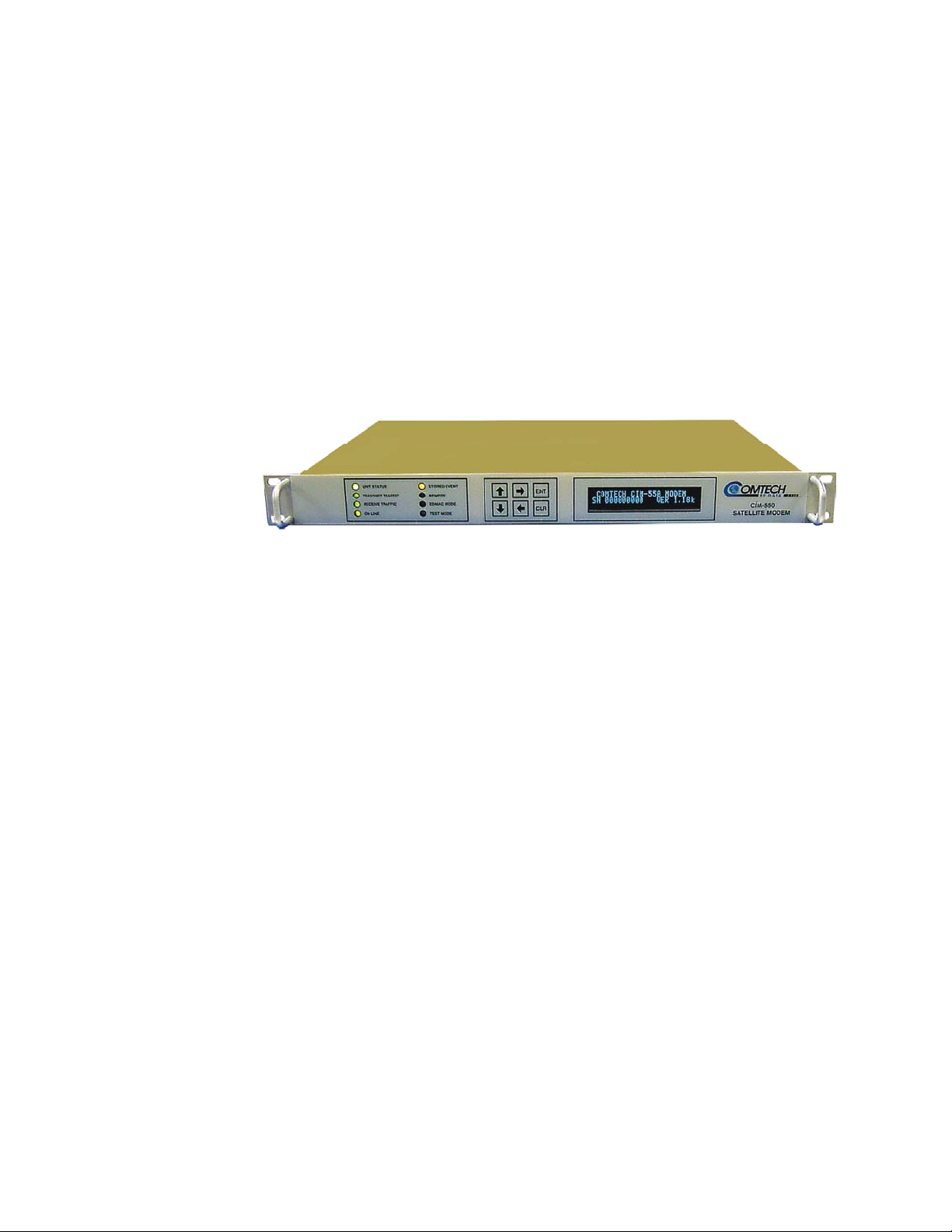
CiM-550
IP-Enabled
Satellite
Modem
Chapter 1. Introduction
Introduction 1
Major Assemblies 2
Options 4
Specifications 6
Dimensional Envelope 11
1.1 INTRODUCTION
The CiM-550 is a high-performance, low-cost, IP-enabled satellite modem designed for
closed network Single Channel Per Carrier (SCPC) links. It is ideal for many VSAT
applications. Offering a range of data rates from 2.4 to 2048 kbps in 1 bit per second
steps, the modem includes Viterbi forward error correction as standard. The Turbo
Product Codec is available as an option.
The modem is compact, 1U high and 12 inches deep, and consumes only 25 watts
typically. It has the following configuration and control capabilities:
Front panel VFD display and keypad for local configuration and control
Rear panel Remote Control Serial interface (DB9) for modem configuration and
control.
Rear panel Console Port (RJ-11) for Ethernet interface configuration and control.
Rear panel Ethernet Data interface (RJ-45).
1
Page 28

CiM-550 IP Enabled Satellite Modem Rev. 2
Introduction CD/CIM550.IOM
1.2 MAJOR ASSEMBLIES
Assembly Description
PL/0391 Modem Card
PL/9161-1 IP Module
1.3 STANDARD FEATURES
10baseT/100baseT Ethernet Interface
Static IP routing for unicast and multicast
Powerful network management
Web Server interface for complete product management
SNMP with private MIB
Telnet interface for remote product M & C
Console Port interface for local network management
Configurable serial interface (EIA-232 or RS485) for local management
Remote software/firmware upgrade via FTP
Configuration backup and restore via FTP
Local software/firmware via console port
Data rates from 2.4 to 2048 kbps
Symmetric as well as asymmetric operation for maximum bandwidth efficiency
Automatic Uplink Power Control (AUPC)
CDM-550 Emulation Mode
1.3.1 AUPC
An important innovation in the CiM-550 is the addition of Automatic Uplink Power
Control (AUPC). This feature enables the modem to automatically adjust its output
power to maintain the Eb/No of the remote end of the satellite link constant. This
provides protection against rain fading, a particularly severe problem with Ku-band links.
To accomplish this, the framed mode of operation must be used, and the distant end
modem constantly sends back information about the demodulator Eb/No using reserved
bytes in the overhead structure. Using the Eb/No, the local modem then adjusts its output
power, and hence, a closed-loop feedback system is created over the satellite link.
A benefit of this feature is that whenever framed operation is selected, the remote
demodulator’s Eb/No can be viewed from the front panel display of the local modem.
2
Page 29

CiM-550 IP Enabled Satellite Modem Rev. 2
Introduction CD/CIM550.IOM
1.3.2 SOFTWARE
The internal software is both powerful and flexible, permitting storage and retrieval of up
to 10 different modem configurations. The modem uses ‘flash memory’ technology
internally, and new firmware can be uploaded to the unit from an external PC. This
simplifies software upgrading, and updates can now be sent via the Internet, E-mail, or on
disk. The upgrade can be performed without opening the unit, by simply connecting the
modem to the serial port of a computer.
1.3.3 VERIFICATION
The unit includes many test modes and loopbacks for rapid verification of the correct
functioning of the unit. Of particular note is the IF loopback, which permits the user to
perform a quick diagnostic test without having to disturb external cabling. During the
loopback, all of the receive configuration parameters are temporarily changed to match
those of the transmit side. When normal operation is again selected, all of the previous
values are restored.
1.3.4 DATA INTERFACES
The CiM-550 includes, as standard, a universal data interface which eliminates the need
to exchange interface cards for different applications. The interfaces offered include:
10baseT/100baseT Ethernet (RJ-45 connector)
EIA-422 (EIA530) DCE
V.35 DCE
Synchronous EIA-232 DCE
Asynchronous EIA-232 (at data rates up to 56 kbaud)
X.21 DTE and DCE
1.3.5 CDM-550 EMULATION MODE
The CiM-550 can be made to operate in CDM-550 emulation mode, where it behaves
exactly like the Comtech EF Data CDM-550 satellite modem. The emulation mode is
selected from the front panel by selecting Configuration/Interface and then selecting
either EIA-422/530, V.35, or EIA-232 as the interface rather than IP. The CiM-550 will
then pass standard serial traffic, like a CDM-550, but will not pass IP traffic. The CiM550 can still be accessed via the ethernet port using Telnet, HTTP, or SNMP.
3
Page 30

CiM-550 IP Enabled Satellite Modem Rev. 2
Introduction CD/CIM550.IOM
1.4 OPTIONS
Enhancing the CiM-550’s performance is easy. Additional features can be added quickly
on site, using the FAST access code purchased from Comtech EF Data. To enable these
features, simply enter the code at the front panel.
Description Software Version
Turbo Product Coding (TPC) 1.0.1 and Later TCP acceleration Future DES Data Encryption 1.0.1 and Later IP Datagram Compression Future IP Header Compression Future Quality of Service (QoS) 1.0.1 and Later Network Address Translation (NAT) Future EasyConnect for non-IP traffic IGMP support for multicast 1.0.1 and Later 1:1 Redundancy with CRS-100 1.0.1 and Later
1.4.1 TURBO PRODUCT CODING (TPC)
The optional Turbo Product Coding (TPC) is a recent development in FEC techniques
that delivers significant performance improvements when compared to Viterbi with
concatenated Reed-Solomon. TPC simultaneously offers increased coding gain,
markedly lower decoding delay (leading to improved TCP/IP performance), and
bandwidth savings of up to 40%. The TPC option includes two modes (BPSK 22/44 and
BPSK 5/16) that permit operation from exceptionally small antennas, where flux density
issues are of concern.
1.4.2 TCP ACCELERATION
To compensate for the TCP performance degradation in a high delay and high BER (Bit
Error Rate) environment, the CiM-550 incorporates an optional proprietary transparent
TCP acceleration mechanism that will allow a TCP session to optimally use the available
link capacity, while preserving end-to-end transport reliability. TCP acceleration will be
subject to user configured Quality of Service (QoS) restrictions for the route.
Future
1.4.3 DES ENCRYPTION WITH ABILITY TO CHANGE KEYS
The CiM-550 optionally supports DES-56 encryption and decryption. Each unit supports
2 encryption keys and 2 decryption keys. The keys are user configurable. Each route can
be assigned to be encrypted by key 1 or key 2 or transmitted in clear.
4
Page 31

CiM-550 IP Enabled Satellite Modem Rev. 2
Introduction CD/CIM550.IOM
1.4.4 IP DATAGRAM COMPRESSION
Optionally, the CiM-550 supports IP datagram compression to provide improved
bandwidth. IP payload is compressed while the IP Headers remain unaffected.
1.4.5 IP HEADER COMPRESSION
Optionally, the CiM-550 supports IP header compression to provide improved bandwidth
usage especially for smaller datagrams where the header overhead could be significant
(e.g. VoIP).
1.4.6 QUALITY OF SERVICE
Quality of Service (QoS) is an optional feature of the CiM-550. A QoS can be assigned
to each route. It dictates the guaranteed minimum and allowable maximum data rate for
that route. The CiM-550 classifies the incoming traffic based on the destination address
and allocates bandwidth based on the configured profile.
1.4.7 NETWORK ADDRESS TRANSLATION (NAT)
Optional NAT is a feature that allows a LAN to use private IP addresses for internal
communications and share a totally different IP address for external communications.
1.4.8 EASYCONNECT FOR NON-IP TRAFFIC
The CiM-550 optionally supports EasyConnect to support non-IP traffic. This allows
the CiM-550 to simultaneously route IP traffic and bridge non-IP traffic, such as IPX.
The non-IP traffic will be subject to user configured QoS restrictions.
1.4.9 IGMP SUPPORT FOR MULTICAST
IGMP is an optional feature in the CiM-550. If enabled, it responds to IGMP queries for
the configured multicast routes on the transmit side and generates IGMP queries on the
receive side. If there are no active IGMP receivers on the LAN it will stop forwarding
the multicast traffic (received from the satellite) to the LAN.
1.4.10 1:1 REDUNDANCY CONFIGURATION
The CiM-550 supports 1:1 redundancy in conjunction with the CRS-100 IF Switch. In a
redundant configuration the primary CiM-550 communicates with the backup CiM-550
for synchronization and status checks. If there is a failure of the primary unit, the
backup CiM-550 assumes the role of the primary modem with minimal disruption to the
traffic. The switchover is transparent to other devices on the LAN.
5
Page 32

CiM-550 IP Enabled Satellite Modem Rev. 2
Introduction CD/CIM550.IOM
1.5 SPECIFICATIONS
SYSTEM SPECIFICATIONS (FULLY ENHANCED)
Frequency Range 52 to 88 MHz, 104 to 176 MHz (option), stability ± 1.5 ppm, 0 to 500 C
Input/Output Impedance 50 and 75 Ohms (Front panel selectable), 17 dB min. return loss
IF Connector BNC, female
Data Interface 10baseT/100baseTX Ethernet (RJ-45 co nnector)
External TX Carrier Off By TTL ‘low’ signal or external contact closure – hardware function
WAN Encapsulation HDLC 1
Data rate range Overall, 2.4 - 2048 kbps
Scrambling Transparent mode, no RS coding - per CCITT V.35
DB25 female, providing: (CDM-550 mode only)
EIA422/EIA530 DCE
V.35 DCE
X.21 DCE and DTE
Sync / Async EIA232
automatically overrides processor
4.8 kbps - 2048 kbps, Uncoded BPSK
9.6 kbps - 2048 kbps, Uncoded QPSK/OQPSK
2.4 kbps - 1024 kbps, Rate 1/2 BPSK
4.8 kbps - 2048 kbps, Rate 1/2 QPSK/OQPSK
7.2 kbps - 2048 kbps, Rate 3/4 QPSK/OQPSK
8.4 kbps - 2048 kbps, Rate 7/8 QPSK/OQPSK
2.4 kbps - 1145 kbps, Rate 21/44 BPSK Turbo
2.4 kbps - 750 kbps, Rate 5/16 BPSK Turbo
(Fully Independent Tx and Rx rates)
EDMAC mode, no RS coding - externally synchronized
Turbo Product Code mode - externally synchronized
6
Page 33

CiM-550 IP Enabled Satellite Modem Rev. 2
Introduction CD/CIM550.IOM
FEC
FEC None: Uncoded BPSK/QPSK/OQPSK
Viterbi: k=7, per IESS 308/309
BPSK: Rate 1/2
QPSK/OQPSK: Rate 1/2, Rate 3/4 and Rate 7/8
Sequential:
k=36 (Rate 1/2) per IESS 309
k= 63 (Rate 3/4) per IESS 309
k= 87 (Rate 7/8)
Turbo Product Codec (Optional plug-in card):
Rate 3/4 QPSK - 2 dimensional
Rate 21/44 BPSK - 3 dimensional
Rate 5/16 BPSK - 3 dimensional
Overhead Framed
5% overhead (Except Turbo BPSK modes, which add 1.5%)
EDMAC/AUPC
AUPC Target Eb/No Range: 0 to 9.9 dB
Max AUPC Range: 0 to 9 dB
Monitor Functions Distant end Eb/No Tx power level increase
Miscellaneous
Front panel Tactile keypad, 6 keys (Up/Down, Left/Right, Enter/Clear)
Vacuum Fluorescent Display (blue) - 2 lines of 24 characters
Loopbacks Internal IF, digital, and near/far
Fault relays Hardware fault, Rx and Tx Traffic Alarms
M&C Interface EIA-232 and EIA-485 (addressable multi-drop)
EIA-485 may be either 2-wire or 4-wire
RJ-11 Command Line Interface (CLI) for control of IP configuration
parameters.
M&C Software EDMAC software for cont rol of local and distant units
NETWORKING PROTOCOLS 1
Address Resolution Protocol (ARP) Configurable static ARP entries
Internet Protocol (IP)
Internet Control Message Protocol (ICMP)
IPv4 Routing Configurable static routes
Internet Group Management Protocol (IGMP v1 & v2)
User Datagram Protocol (UDP)
Transmission Control protocol (TCP)
Simple Network Management Protocol (SNMP v2)
Telnet
7
Page 34

CiM-550 IP Enabled Satellite Modem Rev. 2
Introduction CD/CIM550.IOM
Hyper Text Transfer Protocol (HTTP)
File transfer protocol (FTP)
OPERATIONS & MAINTENANCE 1
Configuration & Management
Console interface
SNMP v2
Private Modem Specific MIB
SNMP MIB II support
Telnet
HTTP
Remote software / firmware upgrade
Local software / firmware upgrade
Traffic statistics
Faults & alarms
Configuration backup & restore
SECURITY
Password Protection
CONSOLE / REMOTE CONTROL PORT 1
Interface EIA-232 or EIA-485 (2- or 4-wire)
1
Not available in CDM-550 mode
MODULATOR
Transmit Filtering 6th order Butterworth, per IESS 308
Frequency Stability
± 1.5 ppm, 0 to 50º C
Harmonics and Spurious < -55 dBc/4 kHz
Transmit On/Off Ratio 55 dB minimum
Phase Noise < 0.24º rms double-sided, 100 Hz to 1 MHz
Output Power 0 to -20 dBm, 0.1dB steps
Accuracy
± 0.5 dB over frequency and temperature
DEMODULATOR
Input Range -30 to -60 dBm
Max Composite Level +35 dBc up to a max of -5 dBm
Acquisition Range
± 1 to ± 30 kHz (1 kHz steps)
Acquisition Time Depends on data rate, FEC rate and acquisition range
8
Page 35

CiM-550 IP Enabled Satellite Modem Rev. 2
Introduction CD/CIM550.IOM
Example:
Clock tracking range ± 100 ppm min.
BER PERFORMANCE
(Met with two adjacent carriers 7 dB higher)
Guaranteed Eb/No, in dB (Typical values in parentheses)
Viterbi ½ ¾ 7/8
10-5 5.4 (4.9) 6.8 (6.3) 7.7 (7.2)
10-6 6.0 (5.5) 7.4 (6.9) 8.4 (7.9)
10-7 6.7 (6.2) 8.2 (7.7) 9.0 (8.6)
Sequential (64 kbps) ½ ¾ 7/8
10-5 4.8 (4.2) 5.8 (5.3) 7.0 (6.6)
10-6 5.2 (4.5) 6.4 (5.8) 7.5 (7.2)
10-7 5.6 (4.8) 6.9 (6.3) 8.0 (7.7)
Turbo Product Codec 3/4(Q) 21/44(B) 5/16(B)
10-6 3.9 (3.5) 2.8 (2.5) 2.3 (2.0)
10-7 4.1 (3.7) 3.1 (2.8) 2.6 (2.3)
At 512 kbps, R1/2 QPSK, ± 30 kHz sweep,
acquisition time = 0.25 seconds, average
10-8 4.3 (4.0) 3.3 (3.0) 2.8 (2.5)
Monitor Functions Eb/No, Frequency Offset, BER, Buffer fill status,
coarse AGC value
ENVIRONMENTAL AND PHYSICAL
Temperature Operating: 0 to 50º C
Power Supply 100 to 240 volts AC, 50/60 Hz
Power Consumption 22 W typical, 30 W maximum
Physical Dimensions 1U high, 12” (305 mm) deep
Weight 7 lbs (3.2 kg)
CE Approvals EN55022 Class B (Emissions)
FCC Approval FCC Part 15 Class B
Storage: -25 to 70º C
EN50082-1 Part 1 (Immunity)
EN60950 (Safety)
9
Page 36

CiM-550 IP Enabled Satellite Modem Rev. 2
Introduction CD/CIM550.IOM
Figure 1-1. Typical Coarse AGC Voltage Characteristic
10
Page 37

CiM-550 IP Enabled Satellite Modem Rev. 2
Introduction CD/CIM550.IOM
1.6 DIMENSIONAL ENVELOPE
Figure 1-2. Cim-550 Dimensional Envelope
11
Page 38

CiM-550 IP Enabled Satellite Modem Rev. 2
Introduction CD/CIM550.IOM
NOTES:
12
Page 39

2.1 UNP ACKING AND INSPECTION
Chapter 2. Installation
Unpacking and Inspection 13 Mounting Kits 13 Configuration 14 Select Internal IF Loop 14 Connect External Cables 14 Connector Description 14
Inspect shipping containers for damage. If shipping containers are damaged, keep them
until the contents of the shipment have been carefully inspected and checked for normal
operation.
Remove the packing list from the outside of the shipping carton. Open the carton and
remove the contents, checking the contents against the packing list. Verify completeness
of the shipment and that the unit functions correctly. If damage is evident, contact the
carrier and Comtech EF Data immediately and submit a damage report. Keep all shipping
materials for the carrier's inspection.
If the unit needs to be returned to Comtech EF Data, please use the original shipping
container.
2.2 MOUNTING KITS
If the CiM-550 is to be mounted in a rack, ensure that there is adequate clearance for
ventilation. The CiM-550 does not include a cooling fan, so care must be taken that too
many units are not mounted on top of each other. The limit is four units, and then a blank
1U panel must be inserted to allow sufficient airflow around the units. In rack systems
where there is high heat dissipation, forced air cooling must be provided by top or bottom
mounted fans or blowers. Under no circumstance should the highest internal rack
temperature be allowed to exceed 50° C.
13
Page 40

CiM-550 IP Enabled Satellite Modem Rev. 2
Installation CD/CIM550.IOM
The CiM-550 is very light - under 7 lbs (3.2 kgs), and very short - 12 ins (305 mm). For
this reason, it has not been designed to have rack slides mounted to the side of the
chassis. However, Comtech EF Data recommends that some method of support within the
rack should be employed, such as rack shelves. If there is any doubt, please consult the
factory.
2.3 CONFIGURATION
There are no internal jumpers to configure, no interface cards to install, and no other
options to install. All configuration is carried out entirely in software. The unit should
first be configured locally, using the front panel keypad and display. The unit will ship
with a default 64 kbps, QPSK, Rate 1/2 configuration. Please refer to the ‘FRONT
PANEL OPERATION’ section for details on how to fully configure the unit for the
desired operating parameters.
2.4 SELECT INTERNAL IF LOOP
Correct operation of the unit may be verified rapidly, without the need for externally
connected equipment. From the top level menu, select TEST, then IF LOOP (refer to the
‘FRONT PANEL OPERATION’ section) The demod should synchronize, and the green
RECEIVE TRAFFIC LED should illuminate. If the unit does not pass this test, call the
factory for assistance.
2.5 CONNECT EXTERNAL CABLES
Having verified correct operation in IF loop, enter the desired configuration, and proceed
to connect all external cables. If difficulties occur, please call the factory for assistance.
Please note that the modulator gives an output power level in the range 0 to -20 dBm, and
the demodulator expects to see a signal in the range -30 to -60 dBm.
2.6 CONNECTOR DESCRIPTION
External cables are attached to connectors on the rear panel of the CiM-550. These
comprise the IEC line input connector, the Receive and Transmit IF connectors, the Data
connector, Alarms connector, Remote Control connector, and Auxiliary Serial connector.
See Appendix K for detailed connector pinouts.
The IEC line input connector contains the ON/OFF switch for the unit. It is also fitted
with two fuses - one each for line and neutral connections (or L1, L2, where appropriate).
These are contained within the body of the connector, behind a small plastic flap.
For 230 volt AC operation, use T0.5A, (slow-blow) 20 mm fuses.
For 115 volt AC operation, use T1A fuses, (slow-blow) 20 mm fuses.
14
Page 41

CiM-550 IP Enabled Satellite Modem Rev. 2
Installation CD/CIM550.IOM
FOR CONTINUED OPERATOR SAFETY, ALWAYS REPLACE THE FUSES
WITH THE CORRECT TYPE AND RATING.
IF Ports - The IF port connectors are both a 50 ohm BNC female type. 75 ohm cable
connectors (male) will have no problem mating with this 50 ohm type.
Data - The primary Data connector for the CiM-550 is the RJ-45 connector providing the
10/100 BaseT Ethernet interface.
In CDM-550 emulation mode, the Data connector is a 25 pin ‘D’ type female (DB25-F).
This connector conforms to the EIA 530 pinout, which allows for connection of different
electrical standards, including EIA-422/530, V.35, and EIA-232. Please note that it is the
responsibility of the user to provide the appropriate cables to connect to this EIA 530
connector. A shielded 25 pin ‘D’ type provides a very solid solution to EMC problems,
unlike the sometimes used V.35 Winchester connector. The pinout for the EIA 530
connector is provided in the next section.
Note that the currently selected interface type is indicated by a small orange LED which
is located immediately above the connector. This provides an easy visual indication to
anyone mating a connector at the rear of the unit.
Alarms - The Alarms connector is a 15 pin 'D' type male (DB15-M). This provides the
user with access to the Form-C relay contacts which indicate the fault status of the unit.
These are typically connected to an external fault monitoring system, often found in
satellite earth stations. In addition, the receive I and Q demodulator samples are provided
on this connector. Connecting these signals to an oscilloscope in X,Y mode will provide
the receive signal constellation diagram, which is a useful diagnostic aid. A pin is also
provided which can mute the transmit carrier. This requires that the pin be shorted to
ground, or a TTL ‘low’, or an EIA-232 ‘high’ signal be applied.
As an aid to antenna pointing, or for driving step-track equipment, an analog AGC signal
is provided on a pin of this connector. The demodulator incorporates three separate AGC
control loops, one of which is analog, and two of which are entirely digital. The first of
these loops keeps the signal level constant at the input to the flash A/D converter in the
final IF stage. This loop has a limited dynamic range (~ 35 dB) and operates on the total
power within the IF bandwidth (which varies with data rate). The characteristics of this
control voltage are shown at the rear of the specifications section.
The pinout details for this connector are provided in the appendices.
Remote Control - The Remote Control connector is a 9 pin 'D' type female (DB9-M).
Access is provided to remote control ports of the modem, both EIA-232 and RS485. The
pinout details for this connector are provided in the next section.
Console Port – The console port is available for local configuration and management of
the Ethernet interface. This port is an EIA-232 port and uses a standard RJ-11.
15
Page 42

CiM-550 IP Enabled Satellite Modem Rev. 2
Installation CD/CIM550.IOM
Auxiliary Serial Port - The Auxiliary Serial connector is an HE1402 3 pin header. A
suitable mate for this connector is AMP part number 281838-3, with three crimp pins,
AMP part number 182734-2, also required. This is an additional EIA-232 serial port,
which is only used when the modem is part of a 1:1 pair. The pinout details for this
connector are provided in the next section.
16
Page 43

Chapter 3. Operation
Methods of Operation 17 Front Panel Operation 18 Telnet Operations 18 Web Server Operation 18 Telnet Operations 18 SNMP Operations 19 Serial Remote Control Operations 18 Serial Command Line Interface (CLI) Operations 18
3.1 METHODS OF OPERATION
The CiM-550 IP Enabled Modem may be setup and operated using any of the following
methods:
User Interface Connection Modem
Front Panel
Serial Remote
Control
Serial Command
Line Interface
(CLI)
Telnet
Web Server
SNMP
Keypad ALL IP Address/Subnet
Serial RS-232/RS-485
via Remote Control
Port B
Serial RS-232 via
Console Port
Ethernet via 10/100
baseT IP interface
Ethernet via 10/100
baseT IP interface
Ethernet via 10/100
baseT IP interface
CiM Functions Reference
Functions
Chapter 4
only
ALL IP Address/Subnet
only
ALL ALL Chapter 11
ALL ALL Chapter 11
ALL ALL Chapter 12
ALL ALL Chapter 13
Chapter 5
17
Page 44

CiM-550 IP Enabled Satellite Modem Rev. 2
Operation CD/CIM550.IOM
LED Panel Keypad Display
UNIT STATUS
TRANSMIT TRAFFIC
RECEIVE TRAF FIC
ON LINE
STORED EVENT
REMOTE
EDMAC MODE
TEST MODE
Figure 3-1. Front Panel
25 Watts, 250 mA max
115 Volt operation - T1A fuses
230 Volt operation - T0.5A fuses
100 - 240~
50/60 Hz
Receiv e IF
2001
Figure 3-2. Rear Panel
3.1.1 FRONT PANEL OPERATION
The front panel provides a menu driven, easy to operate, user interface that provides
control of all modem parameters plus selection of the IP address and network prefix
length. On the front panel of the unit, there are a keypad, the Vacuum Fluorescent
Display (VFD), and eight LED indicators. The user enters data via the keypad, and
messages are displayed on the VFD. The LEDs indicate, in a summary fashion, the status
of the unit. Refer to Chapter 4 for detailed operations.
RS232
RS 422
(EIA 530)
Data Interface
ENT
CLR
V.35
Remote Control B
IP Interface 10/100 BaseT
Alarms
SN
Date
Remote Control A Transmit IF
Aux Serial
Console Port
Console Port
COMTECH
EF DATA CORP
MADE IN THE USA
3.1.2 SERIAL REMOTE CONTROL OPERATIONS
The CiM-550 modem provides a standard serial (EIA-232, EIA-485 4-wire, or EIA-485
2-wire) interface that can be used only for monitor and control of CiM-550 modem
parameters (Monitor and Control of the CiM-550 IP parameters is provided separately via
the Console Port interface). Access to this application is provided via the ‘Remote
Control B’ (DB9) port on the back of the modem. Refer to Chapter 5 for detailed
operations using this interface.
3.1.3 SERIAL COMMAND LINE INTERFACE (CLI) OPERATIONS
Serial Command Line Interface (CLI) via the RJ-11 ‘Console Port’ The CLI for the CiM550 has been combined with the Telnet interface. Refer to Chapter 11 for detailed
operations using this interface.
3.1.4 TELNET OPERATIONS
The CiM-550 modem provides a Telnet interface with an imbedded, easy to use,
multiple-level, menu system that can be used to monitor and control all CiM-550 modem
and IP parameters. Access to this application is provided via the 10/100 Base T IP
interface (RJ-45). Refer to Chapter 11 for detailed operations using this interface.
18
Page 45

CiM-550 IP Enabled Satellite Modem Rev. 2
Operation CD/CIM550.IOM
3.1.5 WEB SERVER OPERATION
The CiM-550 modem provides an embedded web server application that serves standard
HTML web pages that can be used to monitor and control all CiM-550 modem and IP
parameters. These web pages have been designed for optimal performance when using
MicroSoft’s Internet Explorer version 5 or higher. Access to this application is provided
via the 10/100 Base T IP interface (RJ-45). Refer to Chapter 12 for detailed operations
using this interface.
3.1.6 SNMP OPERATIONS
The CiM-550 modem supports Simple Network Management Protocol (SNMP) interface
that can be used to monitor and control all CiM-550 modem and IP parameters. Access
to this application is provided via the 10/100 Base T IP interface (RJ-45). Refer to
Chapter 13 for detailed operations using this interface.
19
Page 46

CiM-550 IP Enabled Satellite Modem Rev. 2
Operation CD/CIM550.IOM
NOTES:
20
Page 47

Chapter 4. Front Panel Menus
4.1 FRONT PANEL OPERATION
The user can fully control and monitor the operation of the CiM-550 modem from the
front panel, using the keypad and display. Nested menus are used, which display all
available options, and prompt the user to carry out a required action.
Front Panel Operation 21 Keypad 21 Menu Tree 23 Menu Screens 27
The display has two lines each of 24 characters. On most menu screens, the user will
observe a flashing solid block cursor, which blinks at a once-per-second rate. This
indicates the currently selected item, digit, or field. Where this solid block cursor would
obscure the item being edited (for example, a numeric field) the cursor will automatically
change to an underline cursor.
If the user were to display the same screen for weeks at a time, the display could become
‘burnt’ with this image. To prevent this, the unit has a ‘screen saver’ feature which will
activate after 1 hour. The top line of the display will show the Circuit ID (which can be
entered by the user) and the bottom line will show the circuit Eb/No value (if the demod
is locked) followed by ‘Press any key....’. The message moves from right to left across
the screen, then wraps around. Pressing any key will restore the previous screen.
4.1.1 KEYPAD
The keypad comprises six individual
key switches, mounted directly behind
a fully sealed membrane overlay. They
have a positive ‘click’ action, which
provides the user with tactile feedback.
These six switches are identified as UP
ARROW, DOWN ARROW, RIGHT
ARROW, LEFT ARROW, ENTER and
CLEAR.
ENT
CLR
21
Page 48

CiM-550 IP Enabled Satellite Modem Rev. 2
Front Panel Menus CD/CIM550.IOM
Key Function
RIGHT ARROW
LEFT ARROW
UP ARROW
DOWN ARROW
ENTER (ENT)
CLEAR (CLR)
Moves the cursor to the right, when it is displayed.
Moves the cursor to the left, when it is displayed.
Used for editing the value at the current cursor position, if
appropriate. If this is a numeric field, this will increment the value.
Used for editing the value at the current cursor position, if
appropriate. If this is a numeric field, this will decrement the value.
Used to accept an edited entry. Most menus prompt the user to
press this key, by displaying the text (PRESS ENTER), (ENTER) or
(ENT). This results in the entry being accepted, and the user is then
returned to the previous menu.
Used to escape from the current operation and return to the previous
menu.
Note: The keypad has an auto-repeat feature. If a key is held down for more than 1 second, the
key action will repeat, automatically, at the rate of 15 keystrokes per second. This is
particularly useful when editing numeric fields, with many digits, such as frequency or
data rate.
4.1.2 VACUUM FLUORESCENT DISPLAY (VFD)
The VFD is an active display showing 2 lines, each of 24 characters. It produces a blue
light, the brightness of which can be controlled by the user. It has greatly superior
viewing characteristics compared to a Liquid Crystal Display (LCD), and does not suffer
problems of viewing angle or contrast.
22
Page 49

CiM-550 IP Enabled Satellite Modem Rev. 2
Front Panel Menus CD/CIM550.IOM
4.1.3 LED INDICATORS
There are 8 LED indicators. The functions of these indicators are shown in the table
below.
Table 4-1. Front Panel LED Indicators
LED Color Condition
Unit Status
Transmit Traffic
Receive Traffic
On line
Stored Event
Remote
Red A Unit Fault exists (Example: PSU fault)
Orange No Unit Faults, but a Traffic Fault exists
Green No Unit Faults, or Traffic Faults
Green No Tx Traffic Faults
Off A Tx Traffic fault exists OR the Tx Carrier is in OFF state
Green
Off An Rx Traffic fault exists (the demod may still be OK)
Green The Unit is On Line, and carrying traffic
Off
Orange
Off There are no Stored Events
Orange
Off
No Rx Traffic Faults (demod and Viterbi decoder are
locked, everything is OK)
The Unit is Off Line (standby) - forced by externally
connected 1:1 or 1:N redundancy system
There is a Stored Event in the log, which can be viewed
from the front panel, or retrieved via the remote control
interface
The Unit is in Remote Mode - local monitoring is possible,
but no local control
The Unit is in Local Mode - remote monitoring is possible,
but no remote control
EDMAC Mode
Test Mode
4.1.4 MENU TREE
The following figures show the menu structure of the CiM-550 front panel menu. The
detailed screens and menus are described in subsequent paragraphs.
Orange Framing on, EDMAC on, and unit defined as Slave
Off
Orange A Test Mode is selected (Example: IF Loopback)
Off There is no Test Mode currently selected
Either no EDMAC, EDMAC Master, or Transparent mode
is selected
23
Page 50

CiM-550 IP Enabled Satellite Modem Rev. 2
O
O
O
Front Panel Menus CD/CIM550.IOM
CIM-55 0 F r ont Panel Menu Tree 1 of 3
COMTECH CIM-550 MODEM
SN 700000007 VER 1.22
CONFIGURE
ALL
TX
RX
FRAME
INTFC
REMCONT
MASK
IMP ED
TEST
NORM
TX-CW
TX-1,0
IF
DIG
I/O
RF
INFO*
MONIT*
STORE/LD**
UTIL**
ODU**
*CONT . ON PAGE 2
**CONT . ON PAGE 3
PRESS ANY KEY
SELECT: CONFIG TEST INFO
MONIT STORE/LD UTIL ODU
ALL
TAKES USER THROUGH
COMPLETE CONFIGURATION
TX
MOD
FREQ
DATA
FEC
ON/OFF
PWR
SCRAM
CLK
TSI
RX
MOD
FREQ
DATA
FEC
ACQ
DESCRAM
CLK
BUF
RSI
Eb/No
FRAME
TRANSPARENT
FRAMED
BPSK,QPSK,OQPSK
EDIT TX FREQUENCY
EDIT TX DATA RATE
VITERBI,TURBO,NONE
ON, OFF, RTI
MANUAL, AUPC
ON, OFF
INT, EXT, LOOP-TIMED
FF, ON
BPSK,QPSK,OQPSK
EDIT RX FREQUENCY
EDIT RX DATA RATE
VITERBI,TURBO,NONE
EDIT RX ACQ SWEEP RANGE
BUFFER, OFF, ON
EDIT RX BUFFER SIZE
FF, ON
EDIT Eb/No ALARM POINT
FF, ON
EDMAC-OFF, EDMAC-ON
INTFC
RS422 ( EIA 53 0)
V.35
RS232
IP
REM CONT
LOCAL
REMOTE
MASK
AGC
Eb/No
RX-AIS
BUF-SLIP
TX-AIS
IMPED
50 OHMS
75 OHMS
EDIT UNIT’S IP ADDRESS 010.006.007.224/16
BAUD RATE,INTERFACE
ACTIVE, MASKED
ACTIVE, MASKED
ACTIVE, MASKED
ACTIVE, MASKED
ACTIVE, MASKED
Figure 4-1. Front Panel Modem Menu Tree (1 of 3)
24
Page 51

CiM-550 IP Enabled Satellite Modem Rev. 2
B
Front Panel Menus CD/CIM550.IOM
CIM-55 0 F r ont Panel Menu Tree 2 of 3
COMTECH CIM-550 MODEM
SN 700000007 VER 1.22
INFO
ALL
TX
RX
BUFF
MASK
EDMAC
ID
FW
MISC
FAST
MONIT
ALARMS
RX-PARAMS
STORED-EVENTS
STATS
AUPC
STORE/LD**
UTIL**
ODU**
**CONT . ON PAGE 3
PRESS ANY KEY
SELECT: CONFIG TEST INFO
MONIT STORE/LD UTIL ODU
ALL
ON
OFF
RTI
TX
Tx: 70.000 1024. 000 VI T
B R1/2 S INT -20.0 RTI N
RX
Rx: 70.000 1024.000 VIT
B R1/2 D NBUF +/-10.0k N
BUFF
DISABLED
MASK
ALARMS MASKED:
RX-AIS TX-AIS
EDMAC
FRAMING : ON
EDMAC MODE: OFF
ID
CIRCUIT ID:
--------------------------------
FW
FIRMWARE: M&C VER 1.22
IP MODULE VER 1. 1. 0_
MISC
MISC: IF-LOOP 50 OHMS
1:1 L INK=IDLE ONLINE
FAST
FAST OPTIONS: 123456789
550T LS MODE: OFF
LIVE ALARMS
UNIT
RECEIVE
TRANSMIT
RX PARAMETERS
RX:Eb/No>12.6 dB f= +1.2k
BER=1.2E-4 BUF=54 AGC=55
STORED EVENTS
VIEW
CLEAR ALL
STATISTICS
VIEW
CLEAR
CONFIGURE
AUPC
UNIT FAULTS: NONE
RX TRAFFIC: NONE
TX TRAFFIC: NONE
LOG08: 11/09/02 16:41:41
OK - DEMOD LOCK (UP/DOWN)
STA000: NO STORED FAULTS
LOGGING INTERVAL:00 ,IMS
(SET 00 TO DISABLE)(ENT)
AUPC: REMOTE Eb/No=06.8dB
TX POWER INCREASE=0.0d
Figure 4-2. Front Panel Modem Menu Tree (2 of 3)
25
Page 52

CiM-550 IP Enabled Satellite Modem Rev. 2
Front Panel Menus CD/CIM550.IOM
CIM-55 0 F r ont Panel Menu Tree 3 of 3
COMTECH CIM-550 MODEM
SN 700000007 VER 1.22
STORE/LD
STORE
LOAD
UTIL
SET-RTC
VFD
ID
MAN-1:1
CENTER-BUF
FAST
PRESS ANY KEY
SELECT: CONFIG TEST INFO
MONIT STORE/LD UTIL ODU
STORE
LOAD
EDIT REAL TIME CLOCK:
10;25:05 10/11/02 (ENT)
EDIT DISPLAY BRIGHTNESS:
100% (PRESS ENTER)
EDIT CIRCUIT ID: (ENTER)
-----------------------PRESS ENT TO FORCE THIS
UNIT TO STBY (1:1 ONLY)
PRESS ENTER TO RE-CENTER
THE RECEIVE BUFFER
STORE CONFIGURATION TO
LOCATION: 00 (ENTER)
LOAD CONFIGURATION FROM
LOCATION: 00 (ENTER)
ODU
(SEE SE PAR ATE
USER' S GUID E)
ENTER NEW CONFIG CODE:
00000000000000000000
TRANSCEIVER CONTROL:
DISABLE ENABLE (ENTER)
Figure 4-3. Front Panel Modem Menu Tree (3 of 3)
26
Page 53

CiM-550 IP Enabled Satellite Modem Rev. 2
Front Panel Menus CD/CIM550.IOM
4.1.5 MENU SCREENS
4.1.5.1 O
PENING SCREEN
COMTECH CiM-550 MODEM
S/N 1209 S/W VER 1.22
4.1.5.2 SELECT
SELECT: CONFIG TEST INFO
MONIT STORE/LD UTIL ODU
DISPLAY SELECTIONS/DESCRIPTION
This is an example of the Opening Screen. Refer to
CDM-550 Manual for correct version information.
This screen is displayed whenever power is first
applied to the unit.
Pressing any key will take the user to the top level
selection screen.
DISPLAY SELECTIONS/DESCRIPTION
CONFIG - Allows the user to fully configure the unit.
TEST - Allows the user invoke one of several test
modes (loopbacks, for example).
INFO - Allows the user to view information on the
unit, without having to go into configuration screens.
MONIT - Allows the user to monitor the alarm status
of the unit, to view the log of stored events, and to
display the Receive Parameters screen.
STORE/LD - Allows the user to store and to retrieve
up to 10 different modem configurations.
UTIL - Allows the user to perform miscellaneous
functions, such as setting the Real-time clock,
adjusting the display brightness, etc.
ODU - Allows the user to monitor and control a
Comtech RF Transceiver, if connected
27
Page 54

CiM-550 IP Enabled Satellite Modem Rev. 2
Front Panel Menus CD/CIM550.IOM
4.1.5.2.1 SELECT\CONFIG
DISPLAY SELECTIONS/DESCRIPTION
CONFIG: ALL TX RX FRAME
INTFC REMCONT MASK IMPED
ALL
TX
RX
The ALL menu sub-branch permits the user to
completely configure the unit, being prompted, step
by step, to make choices, or edit data. This is highly
recommended for new users, as it will clearly
demonstrate all the parameters which need to be
set.
SELECT\CONFIG\TX
Allows the user to define, on a parameter-by-parameter basis, the transmit configuration
of the unit. These menu sub-branches would be used if the user wished to change, for
example, just the Transmit frequency.
DISPLAY SELECTIONS/DESCRIPTION
TX: MOD FREQ DATA FEC
ON/OFF PWR SCRAM CLK TSI
SELECT\CONFIG\TX\MODULATION
DISPLAY SELECTIONS/DESCRIPTION
SELECT TX MODULATION:
BPSK QPSK OQPSK (ENTER)
Note: If a TURBO FEC option is
selected, the modulation type will
be automatically fixed, and the
user will be presented with a
warning screen.
SELECT\CONFIG\TX\FREQUENCY
DISPLAY SELECTIONS/DESCRIPTION
EDIT TX FREQUENCY:
72.2345 MHz (PRESS ENT
Select the digit to be edited. Change the
value of the digit using the UP/DOWN
arrow keys, then press ENTER.
The range of frequencies is from 52 – 88
MHz (70 MHz factory option) or 104 – 176
MHz (140 MHz factory option).
28
Page 55

CiM-550 IP Enabled Satellite Modem Rev. 2
Front Panel Menus CD/CIM550.IOM
SELECT\CONFIG\TX\DATA RATE
DISPLAY SELECTIONS/DESCRIPTION
EDIT TX DATA RATE:
2048.000 kbps(PRESS ENT)
SELECT\CONFIG\TX\FEC TYPE
DISPLAY SELECTIONS/DESCRIPTION
SELECT FEC TYPE: VITERBI
SEQUENTIAL NONE (ENTER)
SELECT FEC TYPE: VITERBI
SEQ TURBO NONE (ENTER
Select the digit to be edited. Change the
value of the digit using the UP/DOWN
arrow keys, then press ENTER.
The overall range of data rates is from 2.4
to 2048 kbps.
Note: The minimum and maximum data
rates are dependent on
modulation type and FEC
encoder rate. If the user changes
the modulation or FEC, and the
currently selected data rate is
then invalid, it will be adjusted
automatically.
Any FEC type except TURBO
If either the Reed-Solomon Codec option
or the Turbo Codec option are not
installed, this menu will be displayed.
FEC screen displayed if the Turbo Codec
option is installed.
SELECT FEC ENCODER RATE:
1/2 3/4 7/8 (PRESS ENTER)
If the Turbo Codec option is installed, the following menu will be displayed:
TX TURBO: 3/4-Q 21/44-B
5/16-B 3/4-OQ (ENTER)
Note: If BPSK is selected, only
Rate 1/2 is permitted. A
warning screen appears if
this sub-branch is entered
when in BPSK mode.
FEC Rate (Turbo Only)
The Rate 3/4 OQPSK is new for
Version 1.19. (For further details,
see Appendix G - ‘FEC Options’.)
29
Page 56

CiM-550 IP Enabled Satellite Modem Rev. 2
Front Panel Menus CD/CIM550.IOM
SELECT\CONFIG\TX\ON-OFF
DISPLAY SELECTIONS/DESCRIPTION
SELECT TX OUTPUT STATE:
ON OFF RTI (ENTER)
ON
OFF
RTI*
* NEW FEATURE RTI means RECEIVE/TRANSMIT INHIBIT. When selected, it
will prevent the TX carrier from being transmitted, until the demodulator is locked.
To avoid the Tx Carrier from being turned off when the demodulator loses lock for a very
short period of time, the demodulator must be unlocked continuously for a period of 10
seconds before the transmit carrier is inhibited. This time interval is fixed and the user
cannot change it.
Note: Having this feature enabled does not affect the internal IF loopback feature. But, please
be aware that if an external IF loopback is attempted (connecting an external cable from
the Tx IF output to the Rx IF input), then this will not work! (The Tx carrier cannot turn on
until the demod is locked, and the demod cannot lock, because the Tx output is off. The
net result is that the demod will not lock, and the Tx carrier will not turn on.
PLEASE USE THE RTI FEATURE WITH EXTREME CARE!.
IMPORTANT
30
Page 57

CiM-550 IP Enabled Satellite Modem Rev. 2
Front Panel Menus CD/CIM550.IOM
SELECT\CONFIG\TX\PWR
DISPLAY SELECTIONS/DESCRIPTION
OUTPUT POWER LEVEL MODE:
MANUAL AUPC (ENTER)
EDIT OUTPUT POWER LEVEL:
-20.0 dBm (PRESS ENTER)
WARNING! AUTO UPLINK PWR
CONTRL NEEDS FRAMED MODE
TARGET Eb/No MAX RANGE
ALARM DEMOD-UNLOCK(ENT)
MANUAL
AUPC
MANUAL display screen
Default value is 3.0 dB, and upper
limit is 9.9 dB
AUPC warning screen is shown if
‘Framed Mode’ is not selected.
See SELECT-CONFIG-FRAME
menu.
AUPC screen if ‘Framed’ mode is
selected.
ALARM
DEMOD
UNLOCK
EDIT TARGET MIN Eb/No OF
REMOTE MODEM:9.9dB (ENT
EDIT MAX PERMITTED POWER
INCREASE: 1dB (ENTER)
SELECT ACTION AT MAXIMUM
TX POWER: NONE TX ALARM
TARGET Eb/No screen
EDIT TARGET Eb/No of
the remote modem.
Default value is 3.0 dB,
and upper limit is 9.9 dB.
MAX RANGE screen
Default value is 1dB, and
upper limit is 9 Db
ALARM screen
NONE
TX
31
Page 58

CiM-550 IP Enabled Satellite Modem Rev. 2
Front Panel Menus CD/CIM550.IOM
ACTION WHEN REMOTE DEMOD
UNLOCKS: NOM-PWR MAX-PWR
SELECT\CONFIG\TX\SCRAM
DISPLAY SELECTIONS/DESCRIPTION
SELECT TX SCRAMBLING
OFF ON (PRESS ENTER)
SELECT\CONFIG\TX\CLK
DISPLAY SELECTIONS/DESCRIPTION
SELECT TX CLOCKING MODE:
INT EXT LOOP-TIMED (ENT)
DEMOD UNLOCK screen
Select the action that will
occur if the remote demod
is unlocked.
NOM-PWR
MAX-PWR
When Transparent mode is selected, a
V.35 scrambler is used. In Framed or
Reed-Solomon modes, a frame
synchronized scrambler is used.
INT
EXT
LOOP-TIMED
INTERNAL - indicates that the CiM-550 will supply a clock to the DTE, which
is derived from its internal high-stability source.
EXTERNAL - indicates that the CiM-550 expects to receive a clock from the
DTE, to which the unit can phase-lock its internal circuits.
LOOP-TIMED - indicates that the transmit timing source should be the receive
clock, from the direction of the satellite. This is a useful mode, in that no external
connection needs to be made in this mode. If the demodulator loses lock, or if
there is no receive signal present, the internal clock is substituted. Note also that
this mode will work even with asymmetric RX and TX data rates.
32
Page 59

CiM-550 IP Enabled Satellite Modem Rev. 2
Front Panel Menus CD/CIM550.IOM
SELECT\CONFIG\TX\TSI
DISPLAY SELECTIONS/DESCRIPTION
SELECT TRANSMIT SPECTRAL
INVERSION: OFF ON(ENTER)
4.1.5.2.2 SELECT\CONFIG\RX
DISPLAY SELECTIONS/DESCRIPTION
RX: MOD FRQ DATA FEC ACQ
DESCRAM CLK BUF RSI Eb/No
SELECT\CONFIG\RX\MOD
TSI - Transmit Spectral Interval
ON
OFF
When in the ON position, and QPSK is
selected, the transmit spectrum is
inverted (which is the same as reversing
the direction of phase rotation in the
modulator). In BPSK, the time-order of
bits out of the FEC encoder is reversed,
to make the modem compatible with
certain other manufacturer’s modems.
DISPLAY SELECTIONS/DESCRIPTION
SELECT RX MODULATION:
BPSK QPSK OQPSK (ENTER)
SELECT\CONFIG\RX\FRQ
DISPLAY SELECTIONS/DESCRIPTION
EDIT RX FREQUENCY:
72.2345 MHz (PRESS ENT)
BPSK
QPSK
OQPSK
Note: If a TURBO FEC option is selected, the
demodulation type will be automatically
fixed, and the user will be presented with a
warning screen.
The range is 52 - 88 MHz (70 MHz factory option) or
104 - 176 MHz (140 MHz factory option).
33
Page 60

CiM-550 IP Enabled Satellite Modem Rev. 2
Front Panel Menus CD/CIM550.IOM
SELECT\CONFIG\RX\DATA
DISPLAY SELECTIONS/DESCRIPTION
EDIT RX DATA RATE:
64.000 kbps (PRESS ENT)
SELECT\CONFIG\RX/FEC
DISPLAY SELECTIONS/DESCRIPTION
SELECT FEC TYPE: VITERBI
SEQUENTIAL NONE (ENTER)
SELECT FEC TYPE: VITERBI
SEQ TURBO NONE (ENTER
The range is 2.4 to 2048 kbps.
Note: The minimum and maximum data rates are
dependent on modulation type and FEC
decoder rate. If the user changes the
modulation or FEC, and the currently
selected data rate is then invalid, it will be
adjusted automatically.
Any FEC type except TURBO
If either the Reed-Solomon Codec option or the
Turbo Codec option are not installed, this menu will
be displayed.
VITERBI
SEQUENTIAL
NONE
FEC screen displayed if the Turbo Codec option is
installed.
VITERBI
SEQ
TURBO
NONE
SELECT FEC ENCODER RATE:
1/2 3/4 7/8 (PRESS ENTER)
If the Turbo Codec option is installed, the following menu will be displayed:
TX TURBO: 3/4-Q 21/44-B
5/16-B 3/4-OQ (ENTER)
Note: If BPSK is selected, only
Rate 1/2 is permitted. A
warning screen appears if
this sub-branch is entered
when in BPSK mode.
FEC Rate (Turbo Only)
The Rate 3/4 OQPSK is new for
Version 1.19. (For further details,
see Appendix G - ‘FEC Options’.)
34
Page 61

CiM-550 IP Enabled Satellite Modem Rev. 2
Front Panel Menus CD/CIM550.IOM
SELECT\CONFIG\RX\ACQ
DISPLAY SELECTIONS/DESCRIPTION
EDIT RX ACQ SWEEP RANGE:
+/- 25 kHz (PRESS ENTER)
The range is +/- 1 kHz to +/- 30 kHz.
The value entered here determines the amount of
frequency uncertainty the demodulator will sweep
over in order to find and lock to an incoming carrier.
When operating at low bit rates, large values of
sweep range (compared to the data rate) will cause
excessively long acquisition times. For example:
selecting +/- 30 kHz with a data rate of 2.4 kbps,
BPSK, will result in an average acquisition time of
around 5 minutes.
SELECT\CONFIG\RX\DESCRAM
DISPLAY SELECTIONS/DESCRIPTION
SELECT RX DE-SCRAMBLING:
ON OFF (PRESS ENTER)
When Transparent mode is selected, a V.35
descrambler is used. In Framed mode, a framesynchronized descrambler is used. It is
recommended that scrambling/descrambling be
used at all times.
SELECT\CONFIG\RX\CLK
DISPLAY SELECTIONS/DESCRIPTION
SELECT RX CLOCKING MODE:
BUFFER ON OFF(PRESS ENT)
When OFF is selected, the Plesiochronous/Doppler
buffer is disabled. The receive clock will then be
derived from the satellite signal, and will therefore
be subject to clock offsets relative to the local
transmit clock, and a small amount (< 5%) clock
jitter, due to the demodulation bit-timing recovery
process at low values of Eb/No.
When ON is selected, the Plesiochronous/Doppler
buffer is enabled. The input to the buffer will be the
signal from the satellite, with any clock offsets and
jitter. The output from the buffer will be derived from
the local TRANSMIT clock. In this way, the receive
data will be perfectly synchronous with this local
clock. The CiM-550 can be operated with
independent transmit receive and transmit data
rates. Even in this configuration, where RX data rate
<> TX data rate, the output clock for the buffer will
be phase locked to the transmit clock.
35
Page 62

CiM-550 IP Enabled Satellite Modem Rev. 2
Front Panel Menus CD/CIM550.IOM
SELECT\CONFIG\RX\BUF
DISPLAY SELECTIONS/DESCRIPTION
EDIT RX BUFFER SIZE:
+/-4096 BITS (PRESS ENT)
SELECT\CONFIG\RX\RSI
DISPLAY SELECTIONS/DESCRIPTION
SELECT RECEIVE SPECTRAL
INVERSION: OFF ON(ENTER)
SELECT\CONFIG\RX\Eb/No
DISPLAY SELECTIONS/DESCRIPTION
EDIT Eb/No ALARM POINT:
2.0 dB (PRESS ENTER)
Edit the size, in bits of the Plesiochronous/Doppler
Buffer.
Values of +/- 256, 512, 1024, 2048 and 4096 bits
are possible. If the buffer is disabled, a warning
message will be displayed if this screen is entered.
This should normally be in the OFF position. When
in the ON position, the receive spectrum is inverted
(which is the same as reversing the direction of
phase rotation in the demodulator). Note that in
BPSK mode, the demodulator will automatically
synchronize to either the normal time-ordering of
bits FEC codeword pairs, or the inverted ordering
used by certain other manufacturers.
The range of values is from 2.0 to 16.0 dB. The user
may select a value here, and if the Eb/No falls
below this value, a receive traffic fault will be
generated.
36
Page 63

CiM-550 IP Enabled Satellite Modem Rev. 2
Front Panel Menus CD/CIM550.IOM
4.1.5.2.3 SELECT\CONFIG\FRAME
DISPLAY SELECTIONS/DESCRIPTION
SELECT FRAMING MODE:
TRANSPARENT FRAMED (ENT)
SELECT\CONFIG\FRAMED
DISPLAY SELECTIONS/DESCRIPTION
SELECT FRAMING OPTION:
EDMAC-OFF EDMAC-ON (ENT)
SELECT EDMAC MODE:
MASTER SLAVE (ENTER)
TRANSPARENT - No framing is selected. No
overhead is added, and the unit will be compatible
with other manufacturer’s equipment, when
operating in a ‘standard’ configuration (IESS 308
filtering, V.35 scrambling, Viterbi).
Embedded Distant-end Monitor And Control is
enabled or disabled in this sub-menu.
If EDMAC-OFF is selected then none of the EDMAC
features are available, even though framing will still
be enabled.
If EDMAC-ON is selected, the user is further
prompted to select whether the unit is an EDMAC
master, or an EDMAC slave:
An EDMAC MASTER is a unit which is local
to the M&C computer, and which passes
messages, via the overhead, to a distant-end
modem.
An EDMAC SLAVE is a unit which is not
local to the M&C computer, which is at the
distant-end of a satellite link.
EDIT DISTANT-END'S ADDR:
0240 (SEE HANDBOOK)(ENT)
37
(FRAMED/ON) EDMAC MASTER
Edit the address of the distant-end
modem which this unit will pass
messages to.
There is a restriction on values
which can be entered here - they
may only be in increments of 10.
This is automatically taken care of the user may not edit the last digit
of the address. This has been
implemented so that a single
MASTER may pass messages for
up to 10 devices at the distant end.
The valid range of addresses is
from 10 to 9990.
Page 64

CiM-550 IP Enabled Satellite Modem Rev. 2
Front Panel Menus CD/CIM550.IOM
EDIT THIS UNIT'S ADDRESS
0245 (SEE HANDBOOK)(ENT)
4.1.5.2.4 SELECT\CONFIG\INTFC
DISPLAY SELECTIONS/DESCRIPTION
DATA INTERFACE: EIA422/530
V.35 EIA-232 IP (ENTER)
(FRAMED/ON) EDMAC SLAVE
The valid range of addresses is
from 1 to 9999, although ‘base 10'
values will be automatically
skipped.
Remember that this is a unit which
is intended to be located at the
distant-end of a link, and will
therefore be under the control of a
MASTER at the other end. This is
the equivalent of putting the unit
into Remote Control mode - no local
control is possible.
EIA-422/530
V.35
EIA-232
IP
Note: Selecting either EIA-422/530, V.35, or EIA-
232 as the interface rather than IP will
change the CiM-550 to CDM-550 emulation
mode. The CiM-550 will then pass standard
serial traffic, like a CDM-550, but will not
pass IP traffic. The CiM can still be
accessed via the ethernet port using Telnet,
HTTP, or SNMP.
If the user selects IP, the following screen is
displayed:
EDIT UNIT’S IP ADDRESS:
010.006.007.224/16 (ENT)
38
Page 65

CiM-550 IP Enabled Satellite Modem Rev. 2
Front Panel Menus CD/CIM550.IOM
4.1.5.2.5 SELECT\CONFIG\REMCONT
DISPLAY SELECTIONS/DESCRIPTION
SELECT REMOTE CONTROL:
LOCAL REMOTE (PRESS ENT)
LOCAL
REMOTE
If LOCAL is selected then remote control will be
disabled. Remote monitoring is still possible.
If REMOTE is selected AND If the unit has not been
defined as an EDMAC SLAVE then the following
sub-menu will be displayed:
SELECT\CONFIG\REMCONT\REMOTE
DISPLAY SELECTIONS/DESCRIPTION
REMOTE CONTROL: BAUDRATE
INTERFACE (PRESS ENTER)
EDIT LOCAL BUS BAUDRATE:
19200 BAUD FORMAT 8-N-1
BAUDRATE
INTERFACE
BAUDRATE screen
Edit the baud rate of the remote control bus,
connected locally to the M&C computer.
Selections are 300, 1200, 2400, 4800, 9600
and 19200 baud are possible.
FORMAT selectionas are: 8-N-1, 7-E-2, 7-O-
2.
The asynchronous character format is FIXED
at 8 data bits, 1 stop bit, no parity (8-N-1).
SELECT. INTERFACE: EIA-232
EIA485-2W EIA485-4W (ENT)
IN EIA-232 MODE THE BUS
ADDRESS IS FIXED AT 0000
EDIT UNIT'S BUS ADDRESS:
0245 (PRESS ENTER)
39
INTERFACE screen
EIA232
EIA485-2W
EIA485-4W
At this point the user will be further prompted
to enter the bus address.
In EIA-232 mode the bus address is
fixed at 0, and this screen is
displayed.
If either RS485 mode is selected, this
screen is displayed.
The valid range of addresses is from
1 to 9999.
Page 66

CiM-550 IP Enabled Satellite Modem Rev. 2
Front Panel Menus CD/CIM550.IOM
4.1.5.2.6 SELECT\CONFIG\MASK
DISPLAY SELECTIONS/DESCRIPTION
ALARM MASK: AGC Eb/No
RX-AIS BUF-SLIP TX-AIS
AGC
Eb/No
RX-AIS
BUF-SLIP
TX-AIS
SELECT\CONFIG\MASK\AGC
DISPLAY SELECTIONS/DESCRIPTION
SELECT AGC ALARM MASK:
ACTIVE MASKED(PRESS ENT)
ACTIVE - If the user selects ACTIVE, then a
Receive Traffic fault will be generated whenever the
demodulator senses that the composite input level
being applied will cause compression in the IF
stages, and hence degrade the performance of the
demodulator.
MASKED - If the user selects MASKED, no alarm
will be generated.
SELECT\CONFIG\MASK\Eb/No
DISPLAY SELECTIONS/DESCRIPTION
SELECT Eb/No ALARM MASK:
ACTIVE MASKED(PRESS ENT)
ACTIVE - If the user selects ACTIVE, then a
Receive Traffic fault will be generated whenever the
demodulator determines that the Eb/No of the
received carrier has fallen below the threshold
defined under CONFIG, RX, Eb/No.
MASKED – If the user selects MASKED, no alram
will be generated.
SELECT\CONFIG\MASK\RX-AIS
DISPLAY SELECTIONS/DESCRIPTION
SEL RX-AIS ALARM MASK:
ACTIVE MASKED(PRESS ENT)
ACTIVE - If the user selects ACTIVE, then a
Receive Traffic fault will be generated whenever the
demodulator senses that the ‘all ones’ condition is
present in the receive data.
MASKED - If the user selects MASKED, no alarm
will be generated.
40
Page 67

CiM-550 IP Enabled Satellite Modem Rev. 2
Front Panel Menus CD/CIM550.IOM
SELECT\CONFIG\MASK\BUF-SLIP
DISPLAY SELECTIONS/DESCRIPTION
SEL BUF-SLIP ALARM MASK:
ACTIVE MASKED(PRESS ENT)
SELECT\CONFIG\MASK\TX-AIS
DISPLAY SELECTIONS/DESCRIPTION
SEL TX-AIS ALARM MASK:
ACTIVE MASKED(PRESS ENT)
4.1.5.2.7 SELECT\CONFIG\IMPED
DISPLAY SELECTIONS/DESCRIPTION
SELECT IF IMPEDANCE:
50 OHMS 75 OHMS (ENTER)
ACTIVE - If the user selects ACTIVE, then a
Receive Traffic fault will be generated whenever the
receive circuitry senses that the buffer has either
underflowed, or overflowed.
MASKED - If the user selects MASKED, no alarm
will be generated.
ACTIVE - If the user selects ACTIVE, then a
Transmit Traffic fault will be generated whenever
the transmit circuitry senses that the ‘all ones’
condition is present in the transmit data.
MASKED - If the user selects MASKED, no alarm
will be generated.
50 Ohms
75 Ohms
4.1.5.3 SELECT\TEST
DISPLAY SELECTIONS/DESCRIPTION
TEST: NORM TX-CW TX-1,0
IF2 DIG2 I/O2 RF2 (ENT)
NORM
TX-CW
(Normal) This clears any test modes or loopbacks, and places the unit
back into an operational state.
(Transmit CW) This is a test mode which forces the modulator to
transmit a pure carrier (unmodulated).
NORM
TX-CW
TX-1,0,
IF LOOP
DIG LOOP
I/O LOOP
41
Page 68

CiM-550 IP Enabled Satellite Modem Rev. 2
Front Panel Menus CD/CIM550.IOM
TX-1,0
IF LOOP
DIG LOOP
I/O LOOP
(Transmit an alternating 1,0,1,0 pattern) This is a test mode which
forces the modulator to transmit a carrier modulated with an
alternating 1,0,1,0 pattern, at the currently selected symbol rate. This
causes two discrete spectral lines to appear, spaced at +/- half the
symbol rate, about the carrier frequency. This mode is used to check
the carrier suppression of the Modulator.
(IF Loopback) This test mode invokes an internal IF loop. This is a
particularly useful feature, as it permits the user to perform a quick
diagnostic test without having to disturb external cabling.
Furthermore, all of the receive configuration parameters are
temporarily changed to match those of the transmit side. When
NORMAL is again selected, all of the previous values are restored.
(Digital Loopback) This test mode invokes a digital loopback, which
loops data at the output of the digital FIR filter on the transmit side,
back into the Viterbi decoder on the receive side. This tests all of the
interface, transmit baseband circuits, FEC encoder, FEC decoder,
and buffer.
(Inward/Outward loopback) This test mode invokes two distinct
loopbacks. The first of these is the inward loop, which takes data
being received from the satellite direction, and passes it directly to the
modulator. Simultaneously, the outward loop is invoked, whereby data
being fed to the transmit data interface is routed directly back out of
the receive data interface.
The three loopback modes are illustrated in the following figure.
42
Page 69

CiM-550 IP Enabled Satellite Modem Rev. 2
Front Panel Menus CD/CIM550.IOM
Figure 4-4. Loopback Modes
43
Page 70

CiM-550 IP Enabled Satellite Modem Rev. 2
Front Panel Menus CD/CIM550.IOM
4.1.6 SELECT\INFO
DISPLAY SELECTIONS/DESCRIPTION
INFO:ALL TX RX BUFF MASK
EDMAC ID FW MISC FAST
4.1.6.1 SELECT\INFO\TX
DISPLAY SELECTIONS/DESCRIPTION
Tx:140.0000 2048.000 VIT
Q R1/2 S LOP -20.0 ON I
The information displayed here is as follows:
ALL
TX
RX
BUFF
MASK
EDMAC
ID
FW
MISC
FAST
Top line: Transmit Frequency and Data Rate
FEC Encoder type (VIT = Viterbi, SEQ = Sequential,
VRS=Viterbi + Reed-Solomon, SRS=Sequential + Reed Solomon
TUR = Turbo, UNC = uncoded)
Bottom line: Modulation type (Q = QPSK, O= OQPSK, B = BPSK)
Code Rate (shows blank in uncoded mode)
Scrambler state (S = Scrambler on, N = Scrambler off)
Clocking Mode (INT = internal, EXT = external, LOP = loop)
Output power level
Transmit output state (ON = on , OFF = off, EOF = external off)
TSI state (I = Transmit Spectral Inversion on, N = off)
44
Page 71

CiM-550 IP Enabled Satellite Modem Rev. 2
Front Panel Menus CD/CIM550.IOM
4.1.6.2 SELECT\INFO\RX
DISPLAY SELECTIONS/DESCRIPTION
Rx: 70.0000 512.000 SEQ
B R3/4 D BUFF +/-23k I
The information displayed here is as follows:
Top line: Receive Frequency
Receive Data Rate
FEC Decoder type (VIT = Viterbi, SEQ = Sequential,
VRS=Viterbi + Reed-Solomon, SRS=Sequential + Reed Solomon,
TUR = Turbo, UNC = uncoded)
Bottom line: Demodulation type (Q = QPSK, O= OQPSK, B = BPSK)
Code Rate (shows blank in uncoded mode)
Descrambler state (D = Descram bler on, N = off)
Clocking Mode
Demod Sweep Acquisition range
RSI state (I = Receive Spectral Inversion on, N = off)
4.1.6.3 SELECT\INFO\BUFF
DISPLAY SELECTIONS/DESCRIPTION
BUFFER: ENABLED (TX=RX)
SIZE: +/-4096 BITS
This displays if the buffer is enabled or disabled,
shows the exact clocking mode (TX=RX, or TX<>
RX), and the buffer size.
45
Page 72

CiM-550 IP Enabled Satellite Modem Rev. 2
Front Panel Menus CD/CIM550.IOM
4.1.6.4 SELECT\INFO\MASK
DISPLAY SELECTIONS/DESCRIPTION
ALARMS MASKED:
RX-AIS TX-AIS
4.1.6.5 SELECT\INFO\EDMAC
DISPLAY SELECTIONS/DESCRIPTION
FRAMING: ON
EDMAC MODE: ON (SLAVE)
4.1.6.6 SELECTINFO\ID
DISPLAY SELECTIONS/DESCRIPTION
This shows, in the same format as the CONFIG,
MASK sub menu, which alarms are currently
masked. If an alarm is not masked, a blank is
displayed in the relevant screen position.
This screen shows the framing mode, EDMAC
mode, and shows if the unit is an EDMAC MASTER
or SLAVE.
CIRCUIT ID
________________________
4.1.6.7 SELECTINFO\FW
DISPLAY SELECTIONS/DESCRIPTION
FIRMWARE: M&C VER 1.22
IP MODULE VER 1. 1. 0_
This displays the user-defined Circuit ID string,
which is entered via the UTIL, ID screen.
46
Page 73

CiM-550 IP Enabled Satellite Modem Rev. 2
Front Panel Menus CD/CIM550.IOM
4.1.6.8 SELECT\INFO\MISC
DISPLAY SELECTIONS/DESCRIPTION
MISC: NORMAL 50 OHMS
1:1 LINK=IDLE ONLINE
4.1.7 SELECT\MONIT
DISPLAY SELECTIONS/DESCRIPTION
MONITOR:ALARMS RX-PARAMS
STORED-EVENTS STATS AUPC
If the user selects ALARMS, the following sub-menu is displayed:
4.1.7.1 SELECT\MONIT\ALARMS
DISPLAY SELECTIONS/DESCRIPTION
This screen shows the following:
Test mode
IF impedance
1:1 link status - if the CRS-100 1:1 module
is being used, this shows the status of the
serial link between the two units.
Redundancy status - either online or
standby (1:1 or 1:N)
ALARMS
RX-PARAMS
STORED-EVENTS
STATS
AUPC
LIVE ALARMS: UNIT
RECEIVE TRANSMIT (ENT)
4.1.7.1.1 SELECT\MON\ALARMS\UNIT
DISPLAY SELECTIONS/DESCRIPTION
UNIT FAULT: -12 VOLT PSU
IS UNDER-VOLTAGE
UNIT
RECEIVE
TRANSMIT
The screen will indicate if there are any Unit Faults.
If not, it will display ‘NONE’.
47
Page 74

CiM-550 IP Enabled Satellite Modem Rev. 2
Front Panel Menus CD/CIM550.IOM
4.1.7.1.2 SELECT\MONIT\ALARMS\RECEIVE
DISPLAY SELECTIONS/DESCRIPTION
RX TRAFFIC: AGC ALARM
The screen will indicate if there are any Receive
Traffic Faults. If not, it will display ‘NONE’.
REDUCE COMPOSITE I/P LVL
4.1.7.1.3 SELECT\MONIT\ALARMS\TRANSMIT
DISPLAY SELECTIONS/DESCRIPTION
TX TRAFFIC: NO CLOCK
The screen will indicate if there are any Transmit
Traffic Faults. If not, it will display ‘NONE’.
DETECTED FROM INTERFACE
4.1.7.2 SELECT\MONIT\RX-PARAMS
DISPLAY SELECTIONS/DESCRIPTION
DEMODULATOR
UNLOCKED (ENTER)
This screen dispalys if the demodulator is unlocked.
RX:Eb/No=05.7dB dF=+11.7k
BER=3.4E-9 BUF=50 AGC=24
Eb/No
dF
BER
BUF
AGC
This shows the value of Eb/No calculated by the demodulator. The value referred to here is the
energy per information bit (Ebi), divided by the noise spectral density (No).
The frequency offset of the received carrier, in kHz, with a displayed resolution of 100 Hz.
This is an estimate of the corrected BER.
(Buffer fill state) This shows the fill state (in percent), of the receive Buffer. After a reset, it will read
50. A value <50 indicates that the buffer is emptying, and >50 indicates that it is filling.
A number between 0 and 99 indicating the gain setting of the coarse AGC loop in the demod. It has
a limited dynamic range, and should not be taken as an accurate measurement of signal level.
If the demodulator is locked, this screen shows the
following:
48
Page 75

CiM-550 IP Enabled Satellite Modem Rev. 2
Front Panel Menus CD/CIM550.IOM
4.1.7.3 SELECT\MONIT\STORED-EVENTS
DISPLAY SELECTIONS/DESCRIPTION
STORED EVENTS: VIEW
CLEAR ALL (PRESS ENTER)
VIEW
CLEAR ALL
4.1.7.3.1 SELECT\MONIT\EVENTS\VIEW
DISPLAY SELECTIONS/DESCRIPTION
LOG23: 30/11/97 10:37:32
FT - DEMOD LOCK (UP/DWN)
LOG24: 30/11/97 10:37:35
OK - DEMOD LOCK (UP/DWN)
The event log can store up to 100 events.
When a fault condition occurs, it is time-stamped
and put into the log. Similarly, when the fault
condition clears, this is also recorded, as shown.
4.1.7.3.2 SELECT\MONIT\STORED-EVENTS\CLEAR ALL
DISPLAY SELECTIONS/DESCRIPTION
STORED EVENTS: VIEW
CLEAR ALL (PRESS ENTER)
MONITOR:ALARMS RX-PARAMS
STORED-EVENTS STATS AUPC
VIEW
CLEAR ALL
If the user selects CLEAR ALL, the event log is
cleared, and the user is taken directly back to the
previous menu. However, if there are faults present
on the unit at this time, they will be re-time-stamped,
and new log entries will be generated.
In accordance with international convention, the
date is shown in DAY-MONTH-YEAR format.
49
Page 76

CiM-550 IP Enabled Satellite Modem Rev. 2
Front Panel Menus CD/CIM550.IOM
4.1.7.4 SELECT\MONIT\STATS
DISPLAY SELECTIONS/DESCRIPTION
LINK STATISTICS: VIEW
CLEAR CONFIGURE (ENTER)
4.1.7.4.1 SELECT\MONIT\STATS\VIEW
DISPLAY SELECTIONS/DESCRIPTION
STA198:02/11/00 10:37:32
16.0,16.0,9.0,9.0(UP/DN)
The top line of the display indicates the log entry number, and the time and date of the
entry.
Note: In accordance with international convention, the date is shown in DAY-MONTH-YEAR
format.
The bottom line of the display shows the statistics data which has been measured and
recorded.
VIEW
CLEAR
CONFIGURE
VIEW
CLEAR ALL
The user may scroll backwards or forwards through
the entries in the statistics log, using the UP/DOWN
arrow keys.
The event log can store up to 250 events.
The meaning and format of the numbers is as follows:
Minimum Eb/No, Average Eb/No, Maximum TPLI, Average TPLI
(where TPLI means Transmit Power Level increase, if AUPC is enabled).
The user defines a measurement interval (see MONITOR, STATS, CONFIGURE) and
during this interval, Eb/No and TPLI are observed, at a one second rate. At the end of this
period, the average Eb/No is calculated and recorded, and the minimum value seen in the
interval. Similarly, the average TPLI is calculated, along with the highest value seen in
the interval.
Notes:
If the demod has lost lock during the measurement interval, the minimum Eb/No
a.
will show ‘LOSS’ rather than indicate a value. However, the average value (while
the demod was locked) will still be calculated and shown. If, on the other hand,
the demodulator has been unlocked for the entire measurement interval, the
average Eb/No will also show ‘LOSS’. (The display will show ‘LOSS,LOSS’.)
If the measured values are greater than, or equal to 16.0 dB, the display will show
b.
16.0 dB.
If AUPC is not enabled, the values of maximum and average TPLI will both show
c.
‘0.0'.
50
Page 77

CiM-550 IP Enabled Satellite Modem Rev. 2
Front Panel Menus CD/CIM550.IOM
Examples:
08.0,13.5,2.5,1.8 means:
Minimum Eb/No observed in the measurement interval = 8.0 dB
Average Eb/No observed in the measurement interval = 13.5 dB
Maximum TPLI observed in the measurement interval = 2.5 dB
Average TPLI observed in the measurement interval = 1.8 dB
LOSS,04.5,0.0,0.0 means:
There was a loss of demod lock during the measurement interval
Average Eb/No observed in the measurement interval = 4.5 dB
Maximum TPLI observed in the measurement interval = 0 dB
Average TPLI observed in the measurement interval = 0 dB
(Which indicates no AUPC activity, or that AUPC is disabled.)
If the user selects CLEAR, the statistics log is cleared, and the user is taken directly back
to the previous menu.
4.1.7.4.2 SELECT\MONIT\STATS\CONFIGURE
DISPLAY SELECTIONS/DESCRIPTION
LOGGING INTERVAL:90 MINS
(SET 00 TO DISABLE)(ENT)
The user is prompted to enter the logging interval
(the period of time over which the statistics will be
measured).
The user can choose 10, 20, 30, 40, 50, 60, 70, 80,
or 90 minutes.
4.1.7.5 SELECT\MONITOR\AUPC
DISPLAY SELECTIONS/DESCRIPTION
FRAMING NOT ENABLED!
(PRESS ENTER)
AUPC: REMOTE Eb/No=14.0dB
TX POWER INCREASE=2.2dB
If AUPC is selected, and the modem is not in
Framed mode, this menu is displayed.
If AUPC is selected, and the modem is in Framed
mode, this menu is displaye d. The top l ine di splays the
value of Eb/No of the demodulat or at th e dist ant end of
the satellite link. The Eb/No will display UNLOCK if the
remote demod is unlocked. The bottom line sh ows
how much the AUPC system has increased the output
power. If AUPC is not enabled, the value of TX
POWER INCREASE will show as 0.0 dB.
51
Page 78

CiM-550 IP Enabled Satellite Modem Rev. 2
Front Panel Menus CD/CIM550.IOM
4.1.8 SELECT\STORE\LD
DISPLAY SELECTIONS/DESCRIPTION
STORE/LOAD CONFIG:
STORE LOAD (PRESS ENTER)
4.1.8.1 SELECT\STORE/LD\STORE
DISPLAY SELECTIONS/DESCRIPTION
STORE CONFIGURATION TO
LOCATION: 10 (ENTER)
YOUR CONFIGURATION HAS
BEEN STORED! (ENTER)
WARNING!LOC 10 CONTAINS DATA!
OVERWRITE? NO YES
STORE
LOAD
These sub-menus permit the user to store or load
up to 10 different modem configurations in the nonvolatile memory of the modem
Select the location to store the current configuration
to, using the UP/DOWN arrow keys, then press
ENTER. Locations 1 through 10 are available.
If the selected location does not contain a previously
stored configuration, the following screen is
displayed:
If, however, the selected location contains a
previously stored configuration, the following screen
is displayed:
Selecting YES will overwrite the existing
configuration at the selected location.
4.1.8.2 SELECT\STORE/LD\LOAD
DISPLAY SELECTIONS/DESCRIPTION
LOAD CONFIGURATION FROM
LOCATION: 10 (ENTER)
THE NEW CONFIGURATION
HAS BEEN LOADED (ENTER)
Select the location to load a configuration from,
using the UP/DOWN arrow keys, then press
ENTER. Locations 1 through 10 are available.
If the selected location contains valid data, the
following screen will be displayed:
If, however, the selected location does not contain
valid data, the following screen will be displayed:
52
Page 79

CiM-550 IP Enabled Satellite Modem Rev. 2
Front Panel Menus CD/CIM550.IOM
WARNING! LOC 10 CONTAINS
NO DATA! (ENTER)
4.1.9 SELECT\UTIL
DISPLAY SELECTIONS/DESCRIPTION
UTILITY: SET-RTC DISPLAY
MAN-1:1 RECENTER-BUF ID
4.1.9.1 SELECT\UTIL\ \RTC
DISPLAY SELECTIONS/DESCRIPTION
EDIT REAL TIME CLOCK:
12:00:00 24/04/98 (ENT)
SET-RTC
VFD
ID
MAN-1:1
CENTER-BUF
FAST
Edit the time and date settings of the real-time
clock. This is accomplished by selecting the digit to
be edited, using the LEFT/RIGHT arrow keys. The
value of the digit is then changed using the
UP/DOWN arrow keys.
Note: In accordance with international convention,
the date is shown in DAY-MONTH-YEAR
format.
4.1.9.2 SELECT\UTIL\VFD
DISPLAY SELECTIONS/DESCRIPTION
EDIT DISPLAY BRIGHTNESS:
100% (PRESS ENTER)
4.1.9.3 SELECT\UTIL\MAN-1:1
DISPLAY SELECTIONS/DESCRIPTION
PRESS ENT TO FORCE THIS
UNIT TO STDBY (1:1 ONLY)
100%
75%
50%
25%
If the unit is part of a 1:1 redundant pair of modems,
and this unit, is currently on-line, pressing ENTER
will cause the unit to switch to standby.
53
Page 80

CiM-550 IP Enabled Satellite Modem Rev. 2
Front Panel Menus CD/CIM550.IOM
4.1.9.4 SELECT\UTIL\RECENTER-BUF
DISPLAY SELECTIONS/DESCRIPTION
PRESS ENTER TO RE-CENTER
THE RECEIVE BUFFER
4.1.9.5 SELECT\UTIL\ID
DISPLAY SELECTIONS/DESCRIPTION
EDIT CIRCUIT ID: (ENTER)
THIS IS A TEST MESSAGE
4.1.10 SELECT\ODU
DISPLAY SELECTIONS/DESCRIPTION
TRANSCEIVER CONTROL:
DISABLE ENABLE (ENTER)
Pressing ENTER will cause a forced re-centering of
the Plesiochronous/Doppler buffer.
Only the bottom line is available (24 characters).
The cursor selects the position on the bottom line
(LEFT/RIGHT) and the character is then edited
(UP/DOWN).
The following characters are available:
Space ( ) * + - , . / 0-9 and A-Z.
When the user has composed the string, press
ENTER.
54
Page 81

Chapter 5. Serial Remote Control
5.1 INTRODUCTION
This section describes the protocol and message command set for remote monitor and
control of the CiM-550 Modem.
The electrical interface is either an EIA-485 multi-drop bus (for the control of many
devices) or an EIA-232 connection (for the control of a single device), and data is
transmitted in asynchronous serial form, using ASCII characters. Control and status
information is transmitted in packets, of variable length, in accordance with the structure
and protocol defined in later sections.
EIA-485 55
EIA-232 56
Basic Protocol 56
Packet Structure 57
5.2 EIA-485
For applications where multiple devices are to be monitored and controlled, a full-duplex
(or 4-wire plus ground) EIA-485 is preferred. Half-duplex (2-wire plus ground) EIA485 is possible, but is not preferred.
In full-duplex IA-485 communication there are two separate, isolated, independent,
differential-mode twisted pairs, each handling serial data in different directions. It is
assumed that there is a ‘controller’ device (a PC or dumb terminal), which transmits data,
in a broadcast mode, via one of the pairs. Many ‘target’ devices are connected to this
pair, which all simultaneously receive data from the controller. The controller is the only
device with a line-driver connected to this pair - the target devices only have linereceivers connected.
In the other direction, on the other pair, each target has a tri-state line driver connected,
and the controller has a line-receiver connected. All the line drivers are held in highimpedance mode until one (and only one) target transmits back to the controller.
Each target has a unique address, and each time the controller transmits, in a framed
‘packet’ of data, the address of the intended recipient target is included. All of the targets
receive the packet, but only one (the intended) will reply. The target enables its output
line driver, and transmits its return data packet back to the controller, in the other
direction, on the physically separate pair.
55
Page 82

CiM-550 IP Enabled Satellite Modem Rev. 2
Serial Remote Control CD/CIM550.IOM
EIA 485 (full duplex) summary:
Two differential pairs - one pair for controller to target, one pair for target to
controller.
Controller-to-target pair has one line driver (controller), and all targets have line-
receivers.
Target-to-controller pair has one line receiver (controller), and all targets have tri-
state drivers.
5.3 EIA-232
This a much simpler configuration in which the controller device is connected directly to
the target via a two-wire-plus-ground connection. Controller-to-target data is carried, via
EIA-232 electrical levels, on one conductor, and target-to-controller data is carried in the
other direction on the other conductor.
5.4 BASIC PROTOCOL
Whether in EIA-232 or EIA-485 mode, all data is transmitted as asynchronous serial
characters, suitable for transmission and reception by a UART. In this case, the
asynchronous character format is fixed at 8 data bits, one stop bit, no parity. The baud
rate may vary between 50 baud and 19,200 baud.
All data is transmitted in framed packets. The controller is assumed to be a PC or ASCII
dumb terminal, which is in charge of the process of monitor and control. The controller is
the only device which is permitted to initiate, at will, the transmission of data. Targets are
only permitted to transmit when they have been specifically instructed to do so by the
controller.
All bytes within a packet are printable ASCII characters, less than ASCII code 127. In
this context, the Carriage Return and Line Feed characters are considered printable.
All messages from controller to target require a response (with one exception). This will
be either to return data which has been requested by the controller, or to acknowledge
reception of an instruction to change the configuration of the target. The exception to this
is when the controller broadcasts a message (such as Set time/date) using Address 0,
when the target is set to EIA-485 mode.
56
Page 83

CiM-550 IP Enabled Satellite Modem Rev. 2
Serial Remote Control CD/CIM550.IOM
5.5 PACKET STRUCTURE
Controller-to-target:
Start of Packet
<
ASCII
code 60
(1
character)
Example: <0135/TFQ=70.2345{CR}
Target-to-controller:
Start of
Packet
>
ASCII
code 62
(1 character)
Example: >0654/RSW=32{CR}{LF}
Target
Address
(4
characters)
Target
Address
(4 characters)
Address
De-limiter
/
ASCII code
47
(1
character)
Address
De-limiter
/
ASCII
code 47
(1 character)
Instructio
n
Code
(3
characters)
Instruction
Code
(3 characters)
Code
Qualifier
= or ?
ASCII code
61 or 63
(1 character)
Code Qualifier Optional
=, ?, !, or *
ASCII code 61,
63, 33 or 42
(1 character)
Optional
Arguments
(n
characters)
Arguments
(From 0 to n
characters)
End of
Packet
Carriage
Return
ASCII code 13
(1 character)
End of Packet
Carriage
Return, Line
Feed
ASCII code
13,10
(2 characters)
Each of the components of the packet is explained below.
5.5.1 START OF PACKET
Controller to Target: This is the character ‘<’ (ASCII code 61)
Target to Controller: This is the character ‘>’ (ASCII code 62)
Because this is used to provide a reliable indication of the start of packet, these two
characters may not appear anywhere else within the body of the message.
5.5.2 ADDRESS
Up to 9,999 devices can be uniquely addressed. In EIA-232 applications this value is set
to 0. In EIA-485 applications, the permissible range of values is 1 to 9999. It is
programmed into a target unit using the front panel keypad.
The controller sends a packet with the address of a target - the destination of the
packet. When the target responds, the address used is the same address, to
IMPORTANT
indicate to the controller the source of the packet. The controller does not have its
own address.
57
Page 84

CiM-550 IP Enabled Satellite Modem Rev. 2
Serial Remote Control CD/CIM550.IOM
5.5.3 INSTRUCTION CODE
This is a three-character alphabetic sequence which identifies the subject of the message.
Wherever possible, the instruction codes have been chosen to have some significance.
For example TFQ for transmit frequency, RMD for receive modulation type, etc. This
aids in the readability of the message, should it be displayed in its raw ASCII form. Only
upper case alphabetic characters may be used (A-Z, ASCII codes 65 - 90).
5.5.4 INSTRUCTION CODE QUALIFIER
This is a single character which further qualifies the preceding instruction code.
Code Qualifiers obey the following rules:
1) From Controller to Target, the only permitted values are:
= (ASCII code 61)
? (ASCII code 63)
They have these meanings:
The ‘=’ code (controller to target) is used as the assignment operator, and is used to
indicate that the parameter defined by the preceding byte should be set to the
value of the argument(s) which follow it.
For example, in a message from controller to target, TFQ=070.0000 would mean
‘set the transmit frequency to 70 MHz.
The ‘?’ code (controller to target) is used as the query operator, and is used to indicate
that the target should return the current value of the parameter defined by the
preceding byte.
For example, in a message from controller to target, TFQ? would mean ‘return the
current value of the transmit frequency.
58
Page 85

CiM-550 IP Enabled Satellite Modem Rev. 2
Serial Remote Control CD/CIM550.IOM
2) From Target to Controller, the only permitted values are:
= (ASCII code 61)
? (ASCII code 63)
! (ASCII code 33)
* (ASCII code 42)
They have these meanings:
The ‘=’ code (target to controller) is used in two ways:
First, if the controller has sent a query code to a target (for example TFQ?,
meaning ‘what’s the Transmit frequency?’), the target would respond with
TFQ=xxx.xxxx, where xxx.xxxx represents the frequency in question.
Second, if the controller sends an instruction to set a parameter to a particular
value, then, providing the value sent in the argument is valid, the target will
acknowledge the message by replying with TFQ= (with no message arguments).
The ? code (target to controller) is only used as follows:
If the controller sends an instruction to set a parameter to a particular value, then,
if the value sent in the argument is not valid, the target will acknowledge the
message by replying (for example) with TFQ? (with no message arguments).
This indicates that there was an error in the message sent by the controller.
The * code (target to controller) is only used as follows:
If the controller sends an instruction to set a parameter to a particular value, then,
if the value sent in the argument is valid, BUT the modem will not permit that
particular parameter to be changed at that time, the target will acknowledge the
message by replying (for example) with TFQ* (with no message arguments).
The ! code (target to controller) is only used as follows:
If the controller sends an instruction code which the target does not recognize, the
target will acknowledge the message by echoing the invalid instruction, followed
by the ! character with. Example: XYZ!
59
Page 86

CiM-550 IP Enabled Satellite Modem Rev. 2
Serial Remote Control CD/CIM550.IOM
5.5.5 MESSAGE ARGUMENTS
Arguments are not required for all messages. Arguments are ASCII codes for the
characters 0 to 9 (ASCII 48 to 57), period (ASCII 46) and comma (ASCII 44).
5.5.6 END OF PACKET
Controller to Target: This is the ‘Carriage Return’ character (ASCII code 13)
Target to Controller: This is the two-character sequence ‘Carriage Return’, ‘Line Feed’.
(ASCII code 13, and code 10.)
Both indicate the valid termination of a packet.
60
Page 87

CiM-550 IP Enabled Satellite Modem Rev. 2
g
Remote Control CD/CIM550.IOM
Parameter
Type
Command
(Instruction
Code and
qualifier)
Arguments for
Command or
Response to
Query
Description of arguments
(note that all arguments are ASCII numeric
codes, that is, ASCII codes between 48 and 57)
Response to Command
(target to controller)
Query
(Instruction
Code and
qualifier)
Response to
query
(target to
controller)
Tx
Frequency
Tx
Data Rate
Tx
FEC Type
TFQ= 8 bytes Command or Query.
Tx Frequency, 52 MHz to 88 MHz, (70 MHz band)
or 104 MHz to 176 MHz, (140 MHz band).
Resolution = 100Hz.
Example: TFQ=072.9876 (70 MHz option)
TFQ=148.0000 (140 MHz option)
Note: Querying ‘Options Fitted’ (using EID?) will
indicate if the unit is 70 MHz or 140 MHz IF band
TDR= 8 bytes Command or Query.
Tx Data rate, in kbps, between 2.4 kbps and 2048
kbps. Resolution = 1 bps.
Example: TDR=2047.999 (which is 2047.999 kbps)
TFT= 1 byte, value of
1,2,3 or 4
Command or Query.
Tx FEC coding type, where:
0 = None (uncoded - no FEC)
1 = Viterbi
2 = Sequential
3 = Viterbi + Reed-Solomon
4 = Sequential + Reed-Solomon
5 = Rate 3/4 QPSK Turbo (S/W Version < 1.15)
6 = Rate 21/44 BPSK Turbo (S/W Version > 1.14)
7 = Rate 5/16 BPSK Turbo (S/W Version > 1.14)
All other codes invalid.
Example: TFT=1 (which is Viterbi coding)
Note: If the RS Codec option is not installed, and
the ar
ument 3 or 4 is used, the target will return
TFQ= (message ok)
TFQ? (received ok,
but invalid arguments found)
TFQ* (message ok, but not
permitted in current mode)
TDR= (message ok)
TDR? (received ok,
but invalid arguments found)
TFQ* (message ok, but not
permitted in current mode)
TFT= (message ok)
TFT? (received ok,
but invalid argument found)
TFT* (message ok, but not
permitted in current mode)
TFQ? TFQ=xxx.xxxx
(same format as
command
arguments)
TDR? TDR=xxxx.xxx
(same format as
command
arguments)
TFT? TFT=x
(same format as
command
arguments)
61
Page 88

CiM-550 IP Enabled Satellite Modem Rev. 2
Remote Control CD/CIM550.IOM
Parameter
Type
Tx
FEC Code
Rate
Tx
Modulation
Type
Command
(Instruction
Code and
qualifier)
Arguments for
Command or
Response to
Query
TCR= 1 byte, value of
1,3 or 7
TMD= 1 byte, value of
1 or 2 or 3
Description of arguments
(note that all arguments are ASCII numeric
codes, that is, ASCII codes between 48 and 57)
TFT?
If the Turbo Codec option is not installed, and the
argument 5 is used, the target will return TFT?
Use EID? to query the options fitted.
Command or Query.
Tx FEC Code rate, where:
1 = Rate 1/2
3 = Rate 3/4 (must be set for Rate 3/4 Turbo)
7 = Rate 7/8
8 = Rate 21/44 (must set for Rate 21/44 Turbo)*
9 = Rate 5/16 (must set for Rate 5/16 Turbo)*
All other codes invalid.
Example: TCR=1 (which is Rate 1/2)
* Only valid for S/W > 1.14 and EID =5500xx
As a Query, returns 0 if Uncoded is selected for
FEC
Command or Query.
Tx Modulation type, where:
1 = BPSK (must be set for Rate 21/44 or 5/16
Turbo)
2 = QPSK (must be set for Rate 3/4 Turbo
operation)
3 = OQPSK
All other codes invalid.
Example: TMD=2 (which is QPSK)
Response to Command
(target to controller)
TCR= (message ok)
TCR? (received ok,
but invalid argument found)
TCR* (message ok, but not
permitted in current mode for example if Turbo is
selected, and either 1/2 or
7/8 is set)
TMD= (message ok)
TMD? (received ok,
but invalid argument found)
TMD* (message ok, but not
permitted in current mode)
Query
(Instruction
Code and
qualifier)
Response to
query
(target to
controller)
TCR? TCR=x
(same format as
command
argument)
TMD? TMD=x
(same format as
command
argument)
Tx Spectrum
Invert
TSI= 1 byte, value of
0 or 1
Command or Query.
Tx Spectrum Invert selection, where:
0 = Normal,
62
TSI= (message ok)
TSI? (received ok, but
invalid arg. found)
TSI? TSI=x
(same format as
command
Page 89

CiM-550 IP Enabled Satellite Modem Rev. 2
Remote Control CD/CIM550.IOM
Parameter
Type
Tx
Scrambler
Tx Power
Level
Tx Clock
Source
Command
(Instruction
Code and
qualifier)
Arguments for
Command or
Response to
Query
Description of arguments
(note that all arguments are ASCII numeric
codes, that is, ASCII codes between 48 and 57)
1 = Tx Spectrum Inverted
All other codes invalid.
Example:TSI=0 (which is normal)
TSC= 1 byte, value of
0 or 1
Command or Query.
Tx Scrambler state, where:
0 = Off
1 = On (V.35 in transparent mode, synchronous in
framed mode
All other codes invalid.
Example: TSC=1 (which is scrambler On)
TPL= 4 bytes Command or Query.
Tx Output power level between 0 and -20 dBm
(minus sign assumed). Example: TPL=13.4 (which
is
-13.4 dBm)
TCK=
1 byte, value of
1,2 or 3
Command or Query.
Tx Clock source, where:
1 = Internal
2 = External
3 = Loop timed (use Rx satellite clock)
All other codes invalid.
Example: TCK=2 (which is External Clock)
Response to Command
(target to controller)
TSI* (message ok, but not
permitted in current mode)
TSC= (message ok)
TSC? (received ok,
but invalid argument found)
TSQ* (message ok, but not
permitted in current mode)
TPL= (message ok)
TPL? (received ok,
but invalid arguments
found)
TPL* (message ok, but not
permitted in current mode)
TCK= (message ok)
TCK? (received ok,
but invalid argument found)
TCK* (message ok, but not
permitted in current mode)
Query
(Instruction
Code and
qualifier)
Response to
query
(target to
controller)
argument)
TSC? TSCS=x
(same format as
command
argument)
TPL?
TPL=xx.x
(same format as
command
arguments)
TCK?
TCK=x
(same format as
command
argument)
Tx Carrier
On/Off State
TXO=
1 byte, value of
0, 1 or 2
Command or Query.
Tx Carrier On/Off state, where:
0 = Off due to front panel or rem. control command
1 = On
63
TXO= (message ok)
TXO? (received ok,
but invalid argument found)
TXO* (message ok, but not
TXO? TXO=x
(Note that 2 is
not a valid
argument when
used as a
Page 90

CiM-550 IP Enabled Satellite Modem Rev. 2
Remote Control CD/CIM550.IOM
Parameter
Type
Rx
Frequency
Rx Data
Rate
Rx
FEC Type
Command
(Instruction
Code and
qualifier)
Arguments for
Command or
Response to
Query
Description of arguments
(note that all arguments are ASCII numeric
codes, that is, ASCII codes between 48 and 57)
2 = Off due to ext H/W Tx Carrier Off command
(not a valid argument when used as a command)
All other codes invalid.
Example: TXO=1 (which is Tx Carrier On)
RFQ=
8 bytes
Command or Query.
Rx Frequency, 52 MHz to 88 MHz, (70 MHz band)
or 104 MHz to 176 MHz (140 MHz band).
Resolution = 100 Hz.
Example: RFQ=143.4567 (which is 143.4567 MHz)
Note: Querying ‘Options Fitted’ (using EID?) will
indicate if the unit is 70 MHz or 140 MHz IF band
RDR= 8 bytes Command or Query.
Rx Data rate, in bps, between 2.4 kbps and 2048
kbps. Resolution = 1 bps.
Example: RDR=002.400 (which is 2.4 kbps)
RFT= 1 byte, value of
1,2,3 or 4
Command or Query.
Rx FEC decoding type, where:
0 = None (uncoded - no FEC)
1 = Viterbi
2 = Sequential
3 = Viterbi + Reed-Solomon
4 = Sequential + Reed-Solomon
5 = Rate 3/4 QPSK Turbo (S/W Version < 1.15)
6 = Rate 21/44 BPSK Turbo (S/W Version > 1.14)
7 = Rate 5/16 BPSK Turbo (S/W Version > 1.14)
All other codes invalid.
Example: RFT=1 (which is Viterbi coding)
Response to Command
(target to controller)
Query
(Instruction
Code and
qualifier)
Response to
query
(target to
controller)
permitted in current mode) command)
RFQ= (message ok)
RFQ? (received ok,
but invalid arguments found)
RFQ? RFQ=xxx.xxxx
(same format as
command
arguments)
RFQ* (message ok, but not
permitted in current mode)
RDR= (message ok)
RDR? (received ok,
but invalid arguments found)
RDR* (message ok, but not
RDR? RDR=xxxx.xxx
(same format as
command
arguments)
permitted in current mode
RFT= (message ok)
RFT? (received ok,
but invalid argument found)
RFT* (message ok, but not
RFT? RFT=x
(same format as
command
arguments)
permitted in current mode)
64
Page 91

CiM-550 IP Enabled Satellite Modem Rev. 2
Remote Control CD/CIM550.IOM
Parameter
Type
Rx FEC
Code Rate
Command
(Instruction
Code and
qualifier)
Arguments for
Command or
Response to
Query
RCR= 1 byte, value of
1,3 or 7
Description of arguments
(note that all arguments are ASCII numeric
codes, that is, ASCII codes between 48 and 57)
Note: If the RS Codec option is not installed, and
the argument 3 or 4 is used, the target will return
RFT? If the Turbo Codec option is not installed,
and the argument 5, 6 or 7 is used, the target will
return RFT? Use EID? to query the options fitted.
Command or Query.
Rx FEC Code rate, where:
1 = Rate 1/2
3 = Rate 3/4 (must be set for Rate 3/4 Turbo)
7 = Rate 7/8
8 = Rate 21/44 (must set for Rate 21/44 Turbo)*
9 = Rate 5/16 (must set for Rate 5/16 Turbo)*
All other codes invalid.
Example: RCR=1 (which is Rate 1/2)
* Only valid for S/W Version >1.14
As a Query, returns 0 if Uncoded is selected for
FEC
Response to Command
(target to controller)
RCR= (message ok)
RCR? (received ok,
but invalid argument found)
RCR* (message ok, but not
permitted in current mode
Query
(Instruction
Code and
qualifier)
Response to
query
(target to
controller)
RCR? RCR=x
(same format as
command
argument)
Rx
Modulation
Type
Rx
Spectrum
Invert
RMD=
1 byte, value of
1or 2 or 3
RSI= 1 byte, value of
0 or 1
Command or Query.
Rx Modulation type, where:
1 = BPSK (must be set for Rate 21/44 or 5/16
Turbo)
2 = QPSK (must be set for Rate 3/4 Turbo
operation)
3 = OQPSK
All other codes invalid.
Example: RMD=1 (BPSK)
Command or Query.
Rx Spectrum Invert selection, where:
65
RMD= (message ok)
RMD? (received ok,
but invalid argument found)
RMD* (message ok, but not
permitted in current mode)
RSI= (message ok)
RSI? (received ok,
RMD?
RSI?
RMD=x
(same format as
command
argument)
RSI=x
(same format as
command
Page 92

CiM-550 IP Enabled Satellite Modem Rev. 2
Remote Control CD/CIM550.IOM
Parameter
Type
Rx
Descrambler
Rx Demod
Acq Sweep
Width
Rx Clock
Mode
Command
(Instruction
Code and
qualifier)
Arguments for
Command or
Response to
Query
RDS= 1 byte, value of
0 or 1
RSW= 2 bytes,
numerical
RCK= 1 byte, value of
0 or 1
Description of arguments
(note that all arguments are ASCII numeric
codes, that is, ASCII codes between 48 and 57)
0 = Normal
1 = Rx Spectrum Inverted
All other codes invalid.
Command or Query.
Rx De-scrambler state, where:
0 = Off
1 = On (V.35 in unframed mode, synchronous in
framed mode
All other codes invalid.
Example: RDS=1 (which is de-scrambler On)
Command or Query.
Rx ± acquisition sweep range of demodulator, in
kHz, ranging from ± 1 kHz to ± 30 kHz.
Example: RSW=09 (which is 9 kHz)
Command or Query.
Rx Clock mode, where:
0 = Buffer disabled
1 = Buffer enabled
All other codes invalid.
Example: RCK=0 (which is buffer disable)
Response to Command
(target to controller)
but invalid argument found)
RSI* (message ok, but not
permitted in current mode)
RDS= (message ok)
RDS? (received ok,
but invalid argument found)
RDS* (message ok, but not
permitted in current mode)
RSW= (message ok)
RSW? (received ok,
but invalid arguments found)
RSW* (message ok, but not
permitted in current mode)
RCK= (message ok)
RCK? (received ok,
but invalid argument found)
RCK* (message ok, but not
permitted in current mode)
Query
(Instruction
Code and
qualifier)
Response to
query
(target to
controller)
argument)
RDS? RDS=x
(same format as
command
argument)
RSW? RSW=xx
(same format as
command
arguments)
RCK? RCK=x
(same format as
command
argument)
Eb/No Alarm
Point
Rx Buffer
Size
EBA= 4 bytes,
numerical
RBS= 1 byte, value of
1,2,3,4 or 5
Command or Query.
Eb/No alarm point, with a range of Eb/No between
0 and 16 dB. Resolution 0.1 dB.
Example: EBA=12.3 (which is Eb/No = 12.3 dB)
Command or Query.
Rx buffer size, where:
66
EBA= (message ok)
EBA? (received ok,
but invalid arguments found)
RBS= (message ok)
RBS? (received ok,
EBA? EBA=xx.x
(same format as
command
arguments)
RBS? RBS=x
(same format as
Page 93

CiM-550 IP Enabled Satellite Modem Rev. 2
Remote Control CD/CIM550.IOM
Parameter
Type
Unit
Interface
Type
IP Address
and network
prefix
Command
(Instruction
Code and
qualifier)
Arguments for
Command or
Response to
Query
ITF= 1 byte, value of
1,2,3 or 4
IPA= 18 bytes,
numerical
Description of arguments
(note that all arguments are ASCII numeric
codes, that is, ASCII codes between 48 and 57)
1 = +/- 256 bits
2 = +/- 512 bits
3 = +/- 1024 bits
4 = +/- 2048 bits
5 = +/- 4096 bits
Command or Query.
Terrestrial interface type, where:
1 = EIA-422/EIA530 DCE,
2 = V.35 DCE
3 = EIA-232 (sync).
4 = IP interface
All other codes invalid. Example: ITF=2 (V.35)
Command or Query.
IP Address and network prefix in the following
format:
xxx.xxx.xxx.xxx.yy
Where:
xxx.xxx.xxx.xxx is the address and yy is the
network prefix (0-31)
Example: IPA=010.006.030.001/24
Response to Command
(target to controller)
but invalid argument found)
RBS* (message ok, but not
permitted in current mode)
ITF= (message ok)
ITF? (received ok, but
invalid args found)
ITF* (message ok, but not
permitted in current mode)
IPA= (message ok)
IPA? (received ok,
but invalid arguments found)
IPA* (message ok, but not
permitted in current mode)
Query
(Instruction
Code and
qualifier)
Response to
query
(target to
controller)
command
argument)
ITF? ITF=x
(same format
as command
argument)
IPA? IPA=xxx.xxx.xxx
.xxx.yy
(same format as
command
arguments)
Unit
Framing
FRM= 1 byte, value of
0 or 1
Mode
Unit Test TST= 1 byte, value of
Command or Query.
Unit operating mode, where
0 = Unframed - transparent (distant-end M&C not
possible)
1 = Framed (EDMAC distant-end M&C possible)
FRM= (message ok)
FRM? (received ok,
but invalid argument found)
FRM* (message ok, but not
permitted in current mode)
FRM? FRM=x
(same format as
command
argument)
Example: FRM=1 (which is framed)
0 = Normal TST= (message ok) TST? TST=x
67
Page 94

CiM-550 IP Enabled Satellite Modem Rev. 2
g
Remote Control CD/CIM550.IOM
Parameter
Type
Command
(Instruction
Code and
qualifier)
Arguments for
Command or
Response to
Query
Description of arguments
(note that all arguments are ASCII numeric
codes, that is, ASCII codes between 48 and 57)
Mode 0,1,2,3,4 or 5 1 = IF loopback
2 = Digital loopback
3 = I/O loopback
4 = Tx CW
5 = Tx Alternating 1,0 pattern
All other codes invalid. Example TST=4 (which is
transmit CW)
Unit IF
Impedance
IMP= 1 byte, value of
5 or 7
Command or Query.
IF interface impedance, where:
5 = 50 ohms
7 = 75 ohms
All other codes invalid. Example IMP=7 ( 75 ohms)
Unit Alarm
Mask
MSK= 5 bytes, each
with a value of 0
or 1
Command or Query.
Alarm mask conditions, in the form abcde, where:
a = mask Tx AIS alarm, b = mask Rx AGC alarm
c = mask buffer alarms, d = mask Rx AIS alarm
e = mask Eb/No alarm
Setting any of these bytes to 0 unmasks alarm,
setting to 1 masks them. Example: MSK=01011
Response to Command
(target to controller)
TST? (received ok,
but invalid argument found)
TST* (message ok, but not
permitted in current mode)
IMP= (message ok)
IMP? (received ok,
but invalid argument found)
MSK= (message ok)
MSK? (received ok,
but invalid arguments found)
MSK* (message ok, but not
permitted in current mode)
Query
(Instruction
Code and
qualifier)
Response to
query
(target to
controller)
(same format as
command
argument)
IMP? IMP=x
(same format as
command
argument)
MSK? MSK=abcde
(same format as
command
arguments)
EDMAC
Slave
Address
ESA= 4 bytes,
numerical
Command or Query.
EDMAC Slave Address - sets the range of
addresses of distant-end units (modems or
transceivers) which this unit will forward messages
for. Only values which are integer multiples of ten
are permitted. (0010, 0020, 0030, 0040 etc.)
Example: ESA=0890
ESA= (message ok)
ESA? (received ok,
but invalid arguments found)
ESA* (message ok, but not
permitted in current mode for example if ESA= is sent
to a distant-end slave unit)
ESA? ESA=xxxx
(same format as
command
arguments)
Important Note: Setting the value of the EDMAC
Slave Address to 0000 disables this function.
Settin
a valid address here will automatically
68
Page 95

CiM-550 IP Enabled Satellite Modem Rev. 2
Remote Control CD/CIM550.IOM
Parameter
Type
Circuit ID
string
Outdoor Unit
Comms
Command
(Instruction
Code and
qualifier)
Arguments for
Command or
Response to
Query
CID= 24 bytes,
ASCII
ODU= 1 byte, value of
0 or 1
Description of arguments
(note that all arguments are ASCII numeric
codes, that is, ASCII codes between 48 and 57)
define the unit as being an EDMAC Master.
This command is only valid for an EDMAC master.
When used as a Query, it may be sent to an
EDMAC slave, which will respond with the
appropriate address.
Command or Query.
Sets or queries the user-defined Circuit ID string,
which is a fixed length of 24 characters.
Valid characters include:
Space ( ) * + - , . / 0-9 and A-Z.
Command or Query.
Enables or disables communication, via an FSK
serial link, with a Comtech Transceiver (Outdoor
unit).
0 = disabled
1 = enabled
Example: ODU=0
Response to Command
(target to controller)
CID= (message ok)
CID? (received ok,
but invalid arguments found)
ODU= (message ok)
ODU? (received ok,
but invalid arguments found)
ODU* (message ok, but not
permitted in current mode)
Query
(Instruction
Code and
qualifier)
Response to
query
(target to
controller)
CID? CID=xxxxxxxx
xxxxxxxxxxxxxx
x (same format
as command
arguments)
ODU? ODU=x
(same format as
command
arguments)
AUPC
Enable
AUPC
Parameters
AUP= 1 byte, value of
0 or 1
Command or Query.
Enables or disables AUPC (Automatic Uplink
Power Control). 0 = disabled 1 = enabled
Example: APC=0
Note: Framing must be selected for the AUPC
feature to work. If AUPC is selected when Framing
is disabled, APC* will be returned
APP= 6 bytes, Command or Query.
Defines AUPC (Automatic Uplink Power Control)
operating parameters. Has the form abc.cd
Where:
a = Define action on max power condition:
69
AUP= (message ok)
AUP? (received ok,
but invalid arguments found)
AUP* (message ok, but not
permitted in current mode)
APP= (message ok)
APP? (received ok,
but invalid arguments found)
APP* (message ok, but not
permitted in current mode)
AUP? AUP=x
(same format as
command
arguments)
APP? APP=abc.cd
(same format as
command
arguments)
Page 96

CiM-550 IP Enabled Satellite Modem Rev. 2
Remote Control CD/CIM550.IOM
Parameter
Type
Remote
Eb/No
Command
(Instruction
Code and
qualifier)
Arguments for
Command or
Response to
Query
N/A 4 bytes,
numerical
Description of arguments
(note that all arguments are ASCII numeric
codes, that is, ASCII codes between 48 and 57)
0 = do nothing 1 = generate TX alarm
b = Define action on remote demod unlock:
0 = go to nominal power 1 = go to max power
c.c = Target Eb/No value, in dB, for remote demod
d = Maximum increase in Tx Power permitted, in
dB
Example: APP= 015.67
Note: If APP is selected when Framing and/or
AUPC is disabled, APP* will be returned
Query only. (AUPC feature)
Returns the value of Ebi/No of the remote demod,
if Framing is enabled.
Returns 99.9 if demod is unlocked.
Returns xx.x if Framing is not enabled.
Range: between 2 and 16dB. Resolution 0.2 dB.
Example: REB=12.4 (which is Eb/No = 12.4 dB)
For values > 16.0 dB, the reply will be REB=16.0
Response to Command
(target to controller)
Query
(Instruction
Code and
qualifier)
Response to
query
(target to
controller)
N/A REB? REB=xx.x
(see description
for details of
arguments)
Tx Power
level
Increase
Global
Configuratio
n
N/A 3 bytes,
numerical
MGC= 78 bytes, with
numerical
entries, fixed
value entries,
and delimiters
Query only. (AUPC feature)
Returns the increase in Tx power level, in dB (from
the nominal setting) due to the action of AUPC.
Returns x.x if AUPC is not enabled.
Example: PLI=2.3
Command or Query. Global configuration of unit, in
the form: FFF.FFFFDDDD.DDDGRMVSPP.PCX
fff.ffffdddd.dddgrmvswwctt.tbIOTZAAAAAUEEEEB
YYY.YYW, where:
F = Tx Frequency - same as TFQ= (8 bytes)
D = Tx Data Rate - same as TDR= (8 bytes)
70
N/A PLI? PLI=x.x
(see
description for
details of
arguments)
MGC= (message ok)
MGC? (received ok,
but invalid arguments found)
MGC? MGC=FFF.FFF
FDDD.DDDRM
VSPP.PCXfff.ffff
ddd.dddrmvsww
ctt.tbIOTZAAAA
AUEEEEBYY
Y.YYW
Page 97

CiM-550 IP Enabled Satellite Modem Rev. 2
Remote Control CD/CIM550.IOM
Parameter
Type
Command
(Instruction
Code and
qualifier)
Arguments for
Command or
Response to
Query
Description of arguments
(note that all arguments are ASCII numeric
codes, that is, ASCII codes between 48 and 57)
G = Tx FEC Coding type - same as TFT= (1 byte)
R = Tx FEC Code Rate - same as TCR= (1 byte)
M = Tx Modulation - same as TMD= (1 byte)
V = Tx Spectrum Invert - same as TSI= (1 byte)
S = Tx Scrambler State - same as TSC= (1 byte)
P = Tx Power Level - same as TPL= (4 bytes)
C = Tx Clock Source - same as TCK= (1 byte)
X = Tx Carrier Status - same as TXO= (1 byte)
f = Rx Frequency - same as RFQ= (8 bytes)
d = Rx Data Rate - same as RDR= (8 bytes)
g = Rx FEC Decoding type - same as RFT= (1
byte)
r = Rx FEC Code Rate - same as RCR= (1 byte)
m = Rx Modulation - same as RMD= (1 byte)
v = Rx Spectrum Invert - same as RSI= (1 byte)
s = Rx De-scrambler - same as RDS= (1 byte)
w= Rx Sweep Width - same as RSW= (2 bytes)
c = Rx Clock Mode - same as RCM= (1 byte)
t = Eb/No Alarm Point - same as EBA= (4 bytes)
b = Rx Buffer Size - same as RBS= (1 byte)
I = Unit Interface Type - same as ITF= (1 byte)
O =Unit Framing Mode - same as FRM= (1 byte)
T = Unit Test Mode - same as TST= (1 byte)
Z = Unit IF Impedance - same as IMP= (1 byte)
A = Alarm Mask - same as MSK= (5 bytes)
U= ODU Comms - same as ODU= (1 byte)
E= EDMAC Slave address - same as ESA= (4
bytes)
Response to Command
(target to controller)
Query
(Instruction
Code and
qualifier)
Response to
query
(target to
controller)
(same format as
command
arguments)
71
Page 98

CiM-550 IP Enabled Satellite Modem Rev. 2
Remote Control CD/CIM550.IOM
Parameter
Type
Command
(Instruction
Code and
qualifier)
Arguments for
Command or
Response to
Query
Config Store CST= 1 byte,
numerical, 0 to
9
Description of arguments
(note that all arguments are ASCII numeric
codes, that is, ASCII codes between 48 and 57)
B= AUPC enable - same as AUP= (1 byte)
Y = AUPC setup - same as APP= (6 bytes)
W =Stats log interval- same as SSI (1 byte),
Example:
MGC=074.56780064.0001720112.720082.65430
128.0002320116109.81211100000102361115.659
Forces the unit to store the current modem
configuration in Configuration Memory location
defined by the one byte argument (0 to 9).
Example CST=4 (Store current config in location 4)
WARNING: Use with caution! If the location
already contains data it will be automatically
overwritten. If in doubt, query the location first.
Response to Command
(target to controller)
CST= (message ok)
CST? (received ok, but
invalid arguments found)
Query
(Instruction
Code and
qualifier)
CST?n, where
n is 0 to 9
CST?0, or
CST?1, or
CST?2, or
CST?3, or
CST?4, or
CST?5, or
CST?6, or
CST?7, or
CST?8, or
CST?9
Response to
query
(target to
controller)
Return the
same format as
the MGC with
the form:
CST= for a
valid config, and
CST* where no
valid config is
found in that n
Config Load CLD= 1 byte,
numerical, 0 to
9
Re-center
RCB= None Command only.
Buffer
Command only.
Forces the unit to retrieve the Configuration
Memory location defined by the one byte argument
(0 to 9). and to re-program the unit with that stored
configuration.
Forces the unit to re-center the receive
plesiochronous/doppler buffer.
72
CLD= (message ok)
CLD? (message received
N/A N/A
ok, but an invalid argument
was found,
CST* (message ok, but the
requested location does not
contain a valid configuration)
RCB= (message ok) N/A N/A
Page 99

CiM-550 IP Enabled Satellite Modem Rev. 2
p
Remote Control CD/CIM550.IOM
Parameter
Type
Force 1:1
Switch
10dB
attenuator
set
Command
(Instruction
Code and
qualifier)
Arguments for
Command or
Response to
Query
Description of arguments
(note that all arguments are ASCII numeric
codes, that is, ASCII codes between 48 and 57)
This command takes no arguments.
FSW= None Command only.
Forces the unit to toggle the Unit Fail relay to the
‘fail’ state for approx 500ms. If the unit is a 1:1 pair,
and it is currently the ‘On Line’ unit, this will force a
switchover, so the unit will then be in ‘Standby’
mode. The command is always executed by the
unit, regardless of whether it is stand-alone, in a
1:1 pair, or part of a 1:N system.
This command takes no arguments.
ATS= 1 byte, value of
0 or 1
FACTORY USE ONLY
Modulator output 10dB attenuator setting, where
0 = no attenuation
1 = 10 dB attenuation
Example: ATS=0
(Used for power-level calibration)
Response to Command
(target to controller)
Query
(Instruction
Code and
qualifier)
Response to
query
(target to
controller)
FSW= (message ok) N/A N/A
ATS= (message ok)
ATS? (received ok, but
invalid arguments found)
ATS? ATS=n
where n is 0
or 1
ATS* (message ok, but not
permitted in current mode)
Power level
DAC set
Write
EEPROM
Value
DAC= 4 bytes,
numerical
FACTORY USE ONLY
Modulator power output DAC setting. An argument
between 0000 and 4095 is required
Example: DAC=1287
(Used for power-level calibration)
EWR= 7 bytes Command only. FACTORY USE ONLY
A command in the form ddd,aaa, where ddd is a
single byte data value between 0 and 255, and aaa
is a starting address (in the range 0 - 127) within
the serial EEPROM, where the data is to be
written.
Exam
le: EWR=127,104 means write the value
73
DAC= (message ok)
DAC? (received ok, but
invalid arguments found)
DAC* (message ok, but not
permitted in current mode)
EWR= (message ok)
EWR? (received ok,
but invalid arguments found)
EWR* (message ok, but not
permitted in current mode)
DAC? DAC=xxxx
where xxxx
is a value
between 0000
and 4095
N/A N/A
Page 100

CiM-550 IP Enabled Satellite Modem Rev. 2
Remote Control CD/CIM550.IOM
Parameter
Type
Read
EEPROM
Value
Set RTC
Date
Set RTC
Time
Command
(Instruction
Code and
qualifier)
Arguments for
Command or
Response to
Query
Description of arguments
(note that all arguments are ASCII numeric
codes, that is, ASCII codes between 48 and 57)
127 starting at address location 104.
(Used for power-level cal, amongst other things)
N/A 3 bytes Query only. FACTORY USE ONLY
A query in the form aaa where aaa is a starting bit
address (in the range 0 - 127) within the modem’s
serial EEPROM, requesting that the byte stored at
that location be returned. Example: ERD?063
returns the value of the byte stored at location 063.
(Used for power-level cal, amongst other things)
DAY= 6 bytes,
numerical
Command or query
A command in the form ddmmyy, where; dd = day
of the month, between 01 and 31, mm = month of
the year, between 01 and 12 and yy = year,
between 97 and 96 (1997 to 2000, then 2000 to
2096)
Example: DAY=240457 would be April 24, 2057
TIM= 6 bytes,
numerical
Command or query
A command in the form hhmmss, indicating the
time from midnight, where hh = hours, between 00
and 23; mm = minutes, between 00 and 59, and ss
= seconds, between 00 and 59
Example: TIM=231259 would be 23 hours, 12
minutes and 59 seconds from midnight.
Response to Command
(target to controller)
Query
(Instruction
Code and
qualifier)
Response to
query
(target to
controller)
N/A ERD? ERD=xxx
where xxx is a
value between 0
and 255
DAY= (message ok)
DAY? (received ok,
but invalid arguments found)
DAY* (message ok, but not
DAY? DAY=xxxxxx
(same format
as command
arguments)
permitted in current mode)
TIM= (message ok)
TIM? (received ok,
but invalid arguments found)
TIM* (message ok, but not
TIM? TIM=xxxxxx
(same format
as command
arguments)
permitted in current mode)
Clear All
Stored
Events
Set
Statistics
Sample
CAE= None Command only
Instructs the unit to clear all Stored Events
This command takes no arguments.
SSI= 1 byte,
numerical
Command or Query.
Used to set the sample interval for the Statistics
Logging Function.
74
CAE= (message ok) N/A N/A
SSI= (message ok)
SSI? (received ok,
but invalid arguments found)
SSI? SSI=x (see
description for
details of
 Loading...