

Page 1

®
Quality System certified by
®
STEAM
STERILIZER
®
OPERATING MANUAL
Ed. 1
Rev. 5
Date: January 2008
Page 2

TABLE OF CONTENTS
REVISIONS
The following table lists subsequent editions/revisions of the manual.
The “Description” field brief explains the subject of the latest revision.
Ed. Rev. Date Description
1 0 11-02 First issue
1 1 02-03 A few modifications; added new chapter “Replacing the printer paper”
1 2 03-04 A few small modifications; photo on the cover
1 3 11-04 A few small modifications;
Added the menu option “Password”
1 4 01-06 Upgrade (software, interface with Milldrop and Millflash)
1 5 01-08 EEC standards reference updating
TABLE OF CONTENTS
1 - INTRODUCTION............................................................................................................................1
APPLICABLE EUROPEAN DIRECTIVES........................................................................................................1
INTENDED USE.................................................................................................................................................1
PURPOSE OF THE MANUAL...........................................................................................................................2
GENERAL WARNINGS...................................................................................................................................... 2
2 - CONTENTS OF THE PACKAGE...................................................................................................3
DIMENSIONS AND WEIGHT............................................................................................................................ 3
DESCRIPTION OF THE CONTENTS................................................................................................................3
HANDLING THE PRODUCT..............................................................................................................................4
3 - PRODUCT INTRODUCTION..........................................................................................................5
INTRODUCTION................................................................................................................................................5
GENERAL CHARACTERISTICS.........................................................................................................................5
FRONT............................................................................................................................................................... 6
REAR .................................................................................................................................................................7
CONTROL PANEL............................................................................................................................................8
LCD DISPLAY....................................................................................................................................................8
OPERATING CYCLE EXAMPLE........................................................................................................................9
4 - INSTALLATION...........................................................................................................................10
INTRODUCTION..............................................................................................................................................10
COMPARTMENT DIMENSIONS FOR BUILT-IN INSTALLATIONS................................................................10
GENERAL INSTALLATION PRECAUTIONS.................................................................................................. 11
ELECTRICAL CONNECTIONS........................................................................................................................11
CONNECTING THE DATA RECORDING MILLFLASH ...................................................................................11
CONNECTING AN EXTERNAL WATER FILLING TANK................................................................................12
CONNECTING DEMINERALIZER MILLDROP...............................................................................................12
CONNECTING AN EXTERNAL DRAIN TANK.................................................................................................13
DIRECT CONNECTION TO A CENTRALIZED DRAINING POINT..................................................................14
I
Page 3

TABLE OF CONTENTS
5 - FIRST START-UP........................................................................................................................ 15
TURNING ON THE EQUIPMENT.....................................................................................................................15
INITIAL AUTOMATIC TEST.............................................................................................................................15
ACQUISITION AND UPDATING OF THE AMBIENT PRESSURE VALUES.................................................... 15
STAND-BY MODE............................................................................................................................................16
FILLING DISTILLED WATER ...........................................................................................................................17
Manual filling.............................................................................................................................................17
Automatic filling........................................................................................................................................17
MAX LEVEL IN THE INTERNAL/EXTERNAL DRAIN TANK............................................................................18
6 - CONFIGURATION....................................................................................................................... 19
INTRODUCTION...............................................................................................................................................19
STARTING AND ENTERING THE SETUP MODE...........................................................................................19
MEANING OF THE KEYS IN SETUP MODE ................................................................................................... 19
DESCRIPTION OF THE MENU ITEMS ............................................................................................................21
DEFAULTS SETTINGS ....................................................................................................................................23
ACTIVATING CONFIGURATION OPTIONS ...................................................................................................23
Setting the language.................................................................................................................................23
Setting the date........................................................................................................................................23
Setting the time.........................................................................................................................................24
Setting the password................................................................................................................................24
Setting the sterilization programs .............................................................................................................25
Setting the STAND-BY mode...................................................................................................................29
Setting the printing mode..........................................................................................................................30
Setting the tank filling mode......................................................................................................................32
Setting the water draining mode..............................................................................................................32
Acquisition of the ambient pressure..........................................................................................................33
Adjusting the contrast of the liquid crystal display ................................................................................... 34
EXIT THE CONFIGURATION MODE..............................................................................................................34
7 - PREPARING THE MATERIAL .................................................................................................... 35
INTRODUCTION...............................................................................................................................................35
TREATING THE MATERIAL BEFORE STERILIZATION..................................................................................35
ARRANGING THE LOAD .................................................................................................................................36
8 - PROGRAM SELECTION............................................................................................................. 38
INTRODUCTION...............................................................................................................................................38
PROCEDURE...................................................................................................................................................38
9 - RUNNING THE CYCLE.............................................................................................................. 40
INTRODUCTION...............................................................................................................................................40
STARTING THE CYCLE..................................................................................................................................40
PROGRAM EXECUTION..................................................................................................................................41
RESULT OF THE CYCLE................................................................................................................................45
CHECK OF THE CYCLE DATA REPORT........................................................................................................46
MANUAL CYCLE INTERRUPTION..................................................................................................................46
10 - STORING STERILIZED MATERIALS ....................................................................................... 48
INTRODUCTION...............................................................................................................................................48
HANDLING .......................................................................................................................................................48
STORAGE ........................................................................................................................................................48
11 - TEST PROGRAMS.................................................................................................................... 49
INTRODUCTION...............................................................................................................................................49
BOWIE & DICK TEST.......................................................................................................................................49
VACUUM TEST................................................................................................................................................50
APPENDIX A – TECHNICAL CHARACTERISTICS......................................................................... 53
SUMMARY TABLE...........................................................................................................................................53
II
Page 4

TABLE OF CONTENTS
SAFETY DEVICES........................................................................................................................................... 54
WATER SUPPLY CHARACTERISTICS...........................................................................................................55
APPENDIX B – PROGRAMS............................................................................................................56
INTRODUCTION..............................................................................................................................................56
PROGRAM SUMMARY TABLE....................................................................................................................... 57
STERILIZATION PROGRAM DIAGRAM..........................................................................................................59
DIAGRAMS OF THE TEST PROGRAMMES...................................................................................................64
EXAMPLES OF PRINTED REPORTS.............................................................................................................65
APPENDIX C – MAINTENANCE.......................................................................................................67
INTRODUCTION..............................................................................................................................................67
ORDINARY MAINTENANCE PROGRAM........................................................................................................ 67
MAINTENANCE DESCRIPTION......................................................................................................................68
Clean gasket and porthole....................................................................................................................... 68
Clean external surfaces...........................................................................................................................68
Clean sterilization chamber and accessories........................................................................................... 68
Disinfect external surfaces....................................................................................................................... 68
Clean internal distilled water tank ............................................................................................................69
Clean external distilled water tank ...........................................................................................................69
Safety valve maintenance........................................................................................................................69
Clean/replace the drain filter.................................................................................................................... 69
Replace bacteriological filter....................................................................................................................70
Replacing the paper in the printer............................................................................................................70
PERIODIC STERILIZER VALIDATION............................................................................................................71
RECYCLING / DISPOSAL INSTRUCTIONS....................................................................................................71
APPENDIX D – GENERAL PROBLEMS...........................................................................................72
INTRODUCTION..............................................................................................................................................72
ANALYSIS AND RESOLUTION OF PROBLEMS............................................................................................72
APPENDIX E – ALARMS..................................................................................................................75
INTRODUCTION..............................................................................................................................................75
ALARM INTERVENTION .................................................................................................................................75
Alarm during a cycle.................................................................................................................................75
Alarm outside the cycle........................................................................................................................... 76
RESETTING THE SYSTEM............................................................................................................................ 77
ALARM CODES ............................................................................................................................................... 78
ANALYSIS AND RESOLUTION OF PROBLEMS............................................................................................80
APPENDIX F – DIAGRAMS..............................................................................................................86
ELECTRICAL DIAGRAM (BOARD TYPE “G”)................................................................................................. 86
ELECTRICAL DIAGRAM (BOARD TYPE “T”)..................................................................................................87
PLUMBING DIAGRAM..................................................................................................................................... 88
APPENDIX G – DECLARATION OF CONFORMITY ........................................................................89
APPENDIX H – NOTES PER THE OPERATOR ...............................................................................90
APPENDIX Z – TECHNICAL SUPPORT...........................................................................................91
III
Page 5

Page 6
1. INTRODUCTION
INTRODUCTION
Symbols used in the
manual
Dear Customer
Thank you for choosing a product from M.O.COM. Srl. We hope that you will find it completely
satisfactory.
This manual describes all procedures for the correct use of the device and instructions for
deriving the full benefit from its features.
In any case, we will be available to provide explanations and to receive any suggestions you
may have for improving our products or services.
NOTE
PAY SPECIAL ATTENTION TO PARAGRAPHS INDICATED BY THE POINTING FINGER.
WARNING
THIS SYMBOL INDICATES A POTENTIAL DANGER OF INJURY. FOLLOW THE
PROCEDURES DESCRIBED IN THE MANUAL TO AVOID INJURING THE USER
AND/OR OTHERS.
DANGER
THIS SYMBOL INDICATES A POTENTIAL DANGER OF PROPERTY DAMAGE.
FOLLOWS THE INSTRUCTIONS IN THE MANUAL TO PREVENT POTENTIAL
DAMAGE TO MATERIALS, EQUIPMENT OR OTHER PROPERTY.
DANGER
THIS SYMBOL INDICATES A POTENTIAL DANGER DUE TO HIGH TEMPERATURE.
APPLICABLE
EUROPEAN
DIRECTIVES
INTENDED USE
THE MATERIAL THE STERILIZER IS COMPOSED OF MUST BE DISPOSED
ACCORDING TO THE DIRECTIVE 2002/96/CEE
The product described in this manual is manufactured in accordance with the highest safety
standards and doesn't represent any danger for the operator if used according to the following
instructions. The product is in accordance with the following European Directive as applicable:
73/23/CEE, for the approximation to the legislation of the Members States related to low
voltage equipment (and following modifications).
2004/108/CEE, for the approximation to the legislation of the Members States related to the
electromagnetic compatibility (and following modifications);
93/42/CEE, concerning the medical devices (and following modifications
).
The product described in this manual is exclusively intended for the sterilization of solid and
hollow re-usable instruments and porous materials.
WARNING
THE DEVICE MUST ONLY BE USED BY QUALIFIED PERSONNEL. IT MAY
NOT BE USED OR HANDLED BY INEXPERT AND/OR UNAUTHORIZED
PERSONNEL FOR ANY REASON.
THIS DEVICE MUST NOT BE USED FOR THE STERILIZATION OF FLUIDS,
LIQUIDS OR PHARMACEUTICAL PRODUCTS.
NOTE
THE MANUAL INFORMATION ARE SUBJECT TO CHANGES WITHOUT ANY NOTICE.
MO.COM. LTD. CO. WON'T BE RESPONSIBLE FOR DIRECT, INDIRECT, ACCIDENTAL,
CONSEQUENT DAMAGES OR OTHER DAMAGES RELATED TO THE SUPPLY OR THE USE OF
AND
.
ARE REGISTERED TRADEMARKS OF M.O.COM. SRL
SUCH INFORMATION
HIS DOCUMENT MAY NOT BE REPRODUCED, ADAPTED OR T RANSLATED, IN WHOLE OR IN
T
PART, WITHOUT THE PRIOR, WRITTEN AUTHORIZATION OF M.O.COM. SRL
1
Page 7
1. INTRODUCTION
PURPOSE OF THE
MANUAL
GENERAL
WARNINGS
The purpose of this manual is to provide instructions for:
– becoming generally familiar with the product;
– its correct installation and configuration;
– its safe, efficient use ;
– handling materia ls before and after sterilization.
Its appendices also provide:
– the product's general technical specifications;
– sterilization program specifications;
– maintenance;
– troubleshooting;
– a variety of other documentation.
When using this product, always
anything other than its intended purpose.
THE USER IS RESPONSIBLE FOR ALL LEGAL REQUIREMENTS RELATED
TO THE INSTALLATION AND USE OF THIS PRODUCT. THE
MANUFACTURER WILL NOT BE RESPONSIBLE FOR ANY BREAKAGE,
MALFUNCTIONS, PROPERTY DAMAGE OR INJURY IN THE EVENT THAT
THE PRODUCT IS NOT INSTALLED OR USED CORRECTLY.
Please observe the following precautions in order to avoid injury or property damage:
– Use ONLY
– Do not
– Do not
– Do not
distilled water of high quality.
THE USE OF WATER OF INADEQUATE QUALITY CAN SEVERELY
DAMAGE THE DEVICE.
SEE APPENDIX A, TECHNICAL CHARACTERISTICS IN THIS REGARD .
pour water or other liquids on the device;
pour inflammable substances on the device;
use the device in the presence of gas or explosive or inflammable vapors;
follow the instructions in the manual and never use for
WARNING
WARNING
– Before performing any maintenance or cleaning, ALWAYS DISCONNECT the electricity.
WARNING
WHENEVER IT IS NOT POSSIBLE TO DISCONNECT THE ELECTRICITY TO
THE DEVICE, OR IF THE EXTERNAL POWER GRID SWITCH IS FAR AWAY
OR, AT ANY RATE, NOT VISIBLE TO THE MAINTAINER, PLACE A WORK
IN PROGRESS SIGN ON THE EXTERNAL POWER GRID SWITCH AFTER
TURNING IT OFF .
– Make sure the electrical system is grounded
– Do not
– Use only
remove any label or nameplate from the device; request new ones, if necessary.
original replacement parts.
THE FAILURE TO OBSERVE THE ABOVE, RELEASES THE
MANUFACTURER FROM ALL LIABILITY.
conforming to current laws and/or standards;
WARNING
2
Page 8
2. CONTENTS OF THE PACKAGE
CONTENTS OF
THE PACKAGE
DIMENSIONS
AND WEIGHT
DESCRIPTION OF
THE CONTENTS
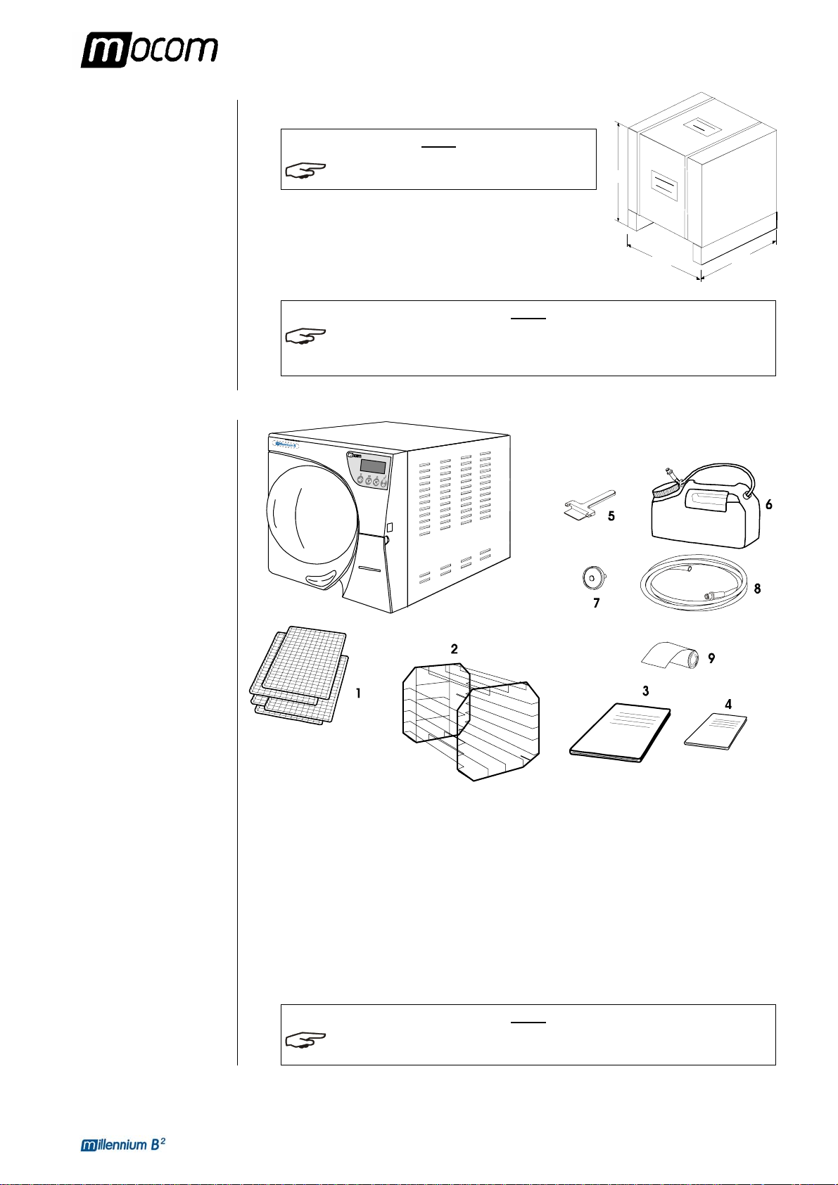
Total weight about 75 kg
NOTE
CHECK THE INTEGRITY OF THE PACKAGE UPON
RECEIPT
.
Once the package is opened, check that:
– the supply matches the specifications of the order (see the
accompanying document);
– that there is no obvious product damage;
NOTE
IN THE CASE OF A WRONG PRODUCT, MISSING PARTS OR ANY TYPE OF DAMAGE,
IMMEDIATELY PROVIDE A DETAILED DESCRIPTION TO THE RESELLER AND THE
TRANSPORTER THAT MADE THE DELIVERY
.
610
690
560
The package contains:
– Steam sterilizer
– Stainless steel wire instrument tray (5 pcs.) (Ref. 1);
– Stainless steel wire tray support (Ref. 2);
– Instruction manual (Ref. 3);
– Warranty certificate (Ref. 4) (see note).
– Tray extractor (Ref. 5);
– Container with quick connector for adding distilled water (about 2 l ) (Ref. 6);
– Extra bacteriological filter (Ref. 7)
– Silicone tube (2 m) for draining water, with quick connector (Ref. 8).
– Spare roll of printer paper (Ref. 9).
NOTE
THE CUSTOMER MUST KEEP THE WARRANTY CERTIFICATE TOGETHER WITH THE
RECEIPT
.
3
Page 9
2. CONTENTS OF THE PACKAGE
HANDLING THE
PRODUCT
Where possible, the packaged product must be handled using suitable mechanical means
(forklift truck, transpallet, etc.) and following the instructions shown on the package.
In the case of manual handling, the product must be lifted by two persons using the handles
cut in the side of the box.
Once removed from the box, the sterilizer must be lifted by two persons and transported on a
cart or other similar device.
WARNING
WE RECOMMEND THAT THE DEVICE BE TRANSPORTED AND STORED
AT A TEMPERATURE NO LOWER THAN 5 °C. PROLONGED EXPOSURE
TO LOW TEMPERATURE AN DAMAGE THE PRODUCT.
NOTE
KEEP THE ORIGINAL PACKAGING AND USE IT WHENEVER THE DEVICE IS TO BE
TRANSPORTED
DURING SHIPMENT.
. THE USE OF DIFFERENT PACKAGING COULD DAMAGE THE PRODUCT
DANGER
BEFORE TRANSPORT, LEAVE THE DEVICE TURNED-OFF FOR ABOUT 30
MINUTES AFTER THE LAST PROGRAM FINISHES AND DRAIN THE
DISTILLED WATER AND USED WATER TANKS SO THAT THE ALL THE
HOT INTERNAL PARTS WILL HAVE TIME TO COOL.
4
Page 10

3. PRODUCT INTRODUCTION
PRODUCT
INTRODUCTION
INTRODUCTION
GENERAL
CHARACTERISTICS
Millennium B² is MO.COM.'s revolutionary type B (EN 13060) small steam sterilizer and a
new de facto standard for safety, performance, flexibility and ease of use.
It is a sophisticated but, at the same time, easy to use device that, thanks to its wide range of
configuration options and patented operating devices, satisfies every need for sterilizing
medical devices, guaranteeing the maximum performance under all conditions.
It also features a better way of relating to users who, rather than having to adapt to the
machine and its characteristics, are able to "converse" with it and configure it to meet their
own needs.
Thanks to its remarkable ease of use, small size and pleasant appearance, it is the ideal
partner for all professional who demand the maximum sterilization safety.
Millennium B² is a completely microprocessor-controlled steam sterilizer with a large (21-
liter) sterilization chamber made of stamped stainless steel.
It is characterized by an advanced fractionated vacuum system for the complete removal of
air, even from hollow, porous materials, and an effective final vacuum drying phase capable of
eliminating all traces of humidity from any load.
Its exclusive steam generation system, effective plumbing circuit and electronic management
(supplemented by high-precision sensors) guarantees high process execution speeds and
excellent thermodynamic parameter stability.
Moreover, its Process Evaluation System constantly monitors all the machine's “vital”
parameters in real-time, guaranteeing absolute safety and a perfect result.
It offers users 11 sterilization programs (of which one completely programmable), all equipped
with customizable, optimized drying for the fast, effective sterilization of the various types of
loads (instruments and materials) use d in a medica l enviro n ment.
Four of these can be selected directly from the control panel, which has a new simplified,
design.
And then, there are interesting options for configuring the preheating mode (based on the
sterilizer's frequency of use), printing the end of cycle report, methods for filling the water
supply, draining the used water and more.
Please refer to the chapter, “Configuration” for more detail.
Finally, Millennium B² has one of the most complete, sophisticated and advanced safety
systems available today to protect users in the case of any electrical, mechanical, thermal or
biological operating anomaly .
NOTE
PLEASE REFER TO APPENDIX A (TECHNICAL CHARACTERISTICS) FOR A DESCRIPTION
OF THE SAFETY DEVICES.
5
Page 11
3. PRODUCT INTRODUCTION
Millflash
interface
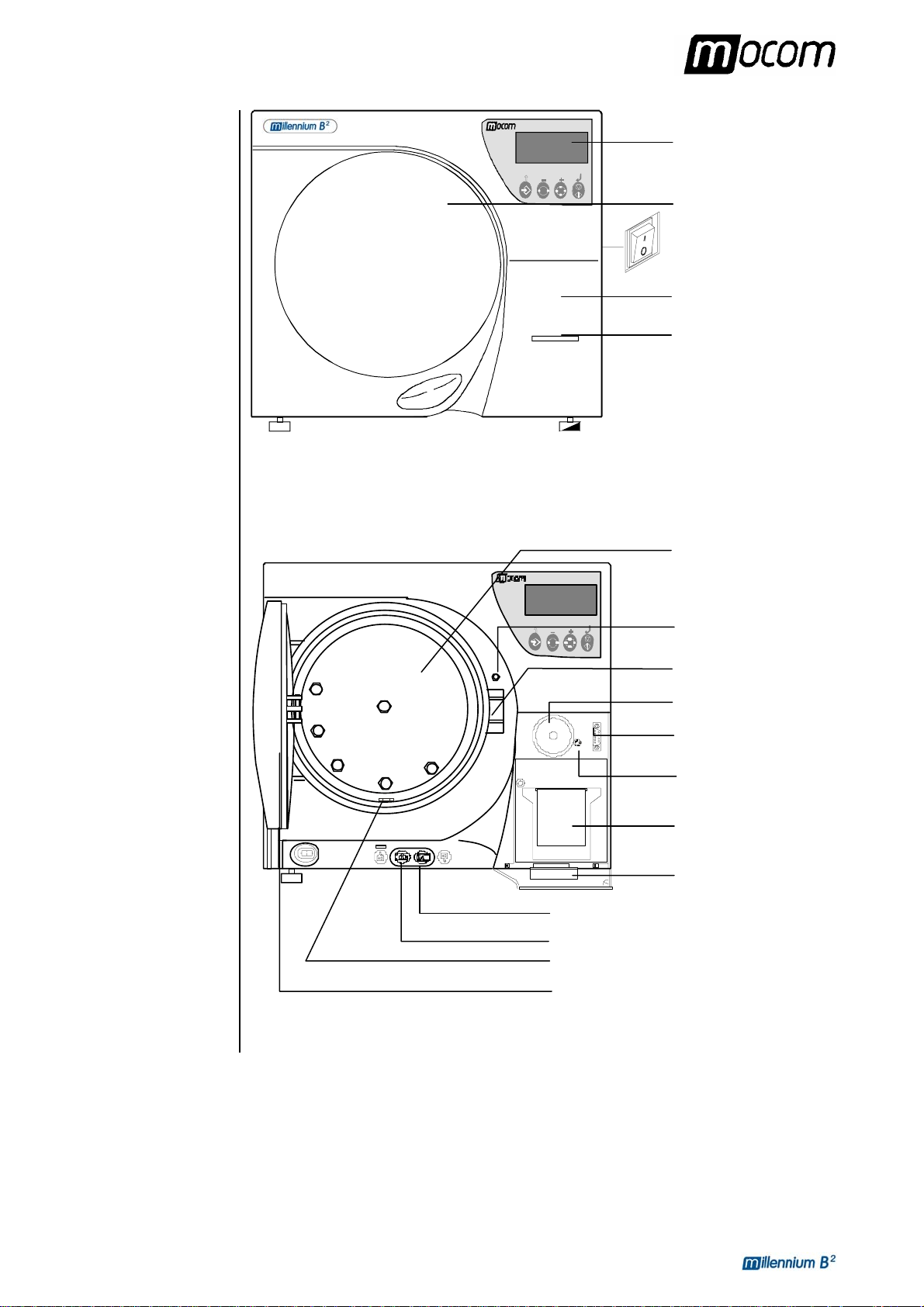
FRONT
LCD display and
control panel
Door
On/Off switch
Service compartment
access panel
Printer paper
output slot
Sterilization
Door microswitch
Motorized
closing system
Bacteriological filter
RS232 serial port
Built-in printer
Used water drain qu ick connector
Distilled water fill quick connector
Water drain plug and filter
Door
Service
6
Page 12
3. PRODUCT INTRODUCTION
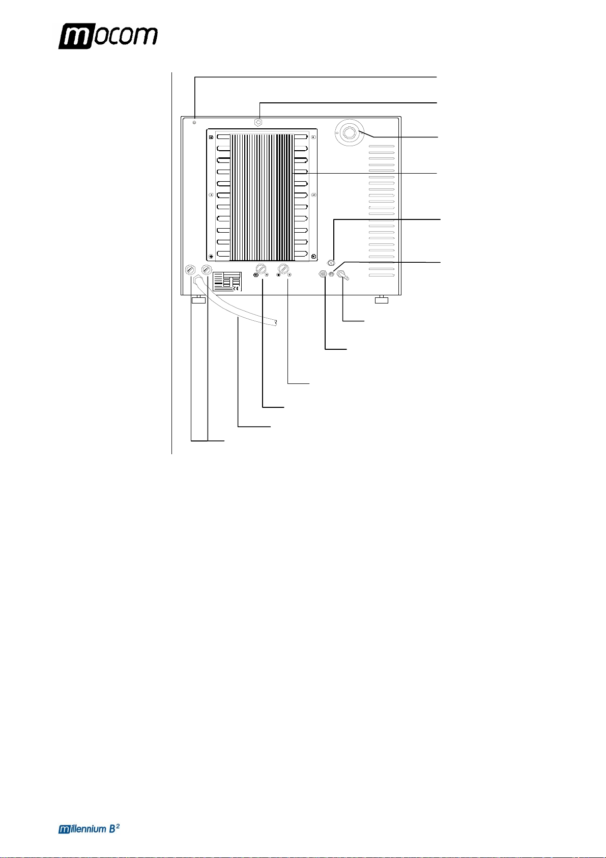
used water tank
distilled water tank
REAR
Connection for automatically filling the
Mains fuses
Power cord
Band heating element safety thermostat and manual
rearm
Steam generator safety thermostat and manual rearm
Connection for directly draining the
Jack for Milldrop
Start/Stop cable
Distilled water tank vent
hole
Safety valve
Heat exchanger
Distilled water tank
draining point
(maintenance)
Jack socket for the
external tank level
sensor (option)
7
Page 13
3. PRODUCT INTRODUCTION
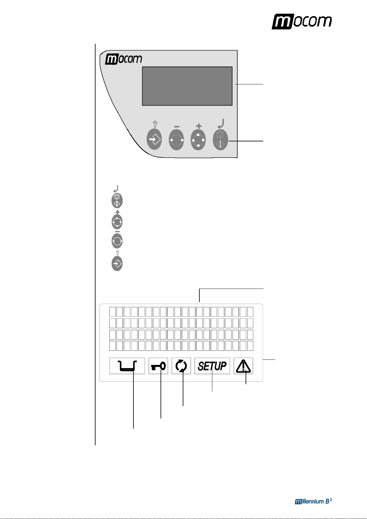
CONTROL
PANEL
LCD DISPLAY
Liquid Crystal Display
(LCD)
Command keys
The function of the command keys differ according to operating mode of the equipment.
Key NORMAL mode SETUP mode
Cycle Start/Stop
Sterilization cycle selectio n
Test cycle selection
Enter Setup mode ESC, quit the current menu
Enter, confirmation of the value/option
selected
Value increment / Forward scroll of
the menu options
Value decrement / Backward scroll of
the menu options
4 lines of 20 characters
Illuminated icon
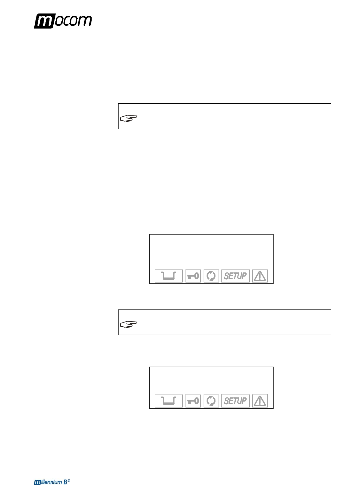
8
Water level
Door status
Process status
Setup status
ALARM
Page 14
3. PRODUCT INTRODUCTION
OPERATING
CYCLE EXAMPLE
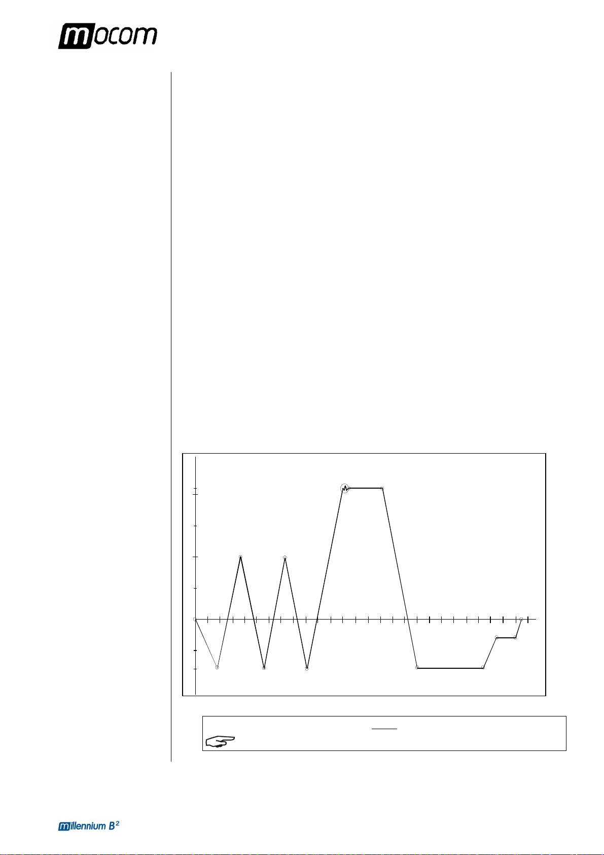
The Millennium B² sterilization program can be described as a succession of phases, each
with a specific purpose.
For example, after loading the material in the chamber, closing the door, selecting the program
and starting the cycle (and the consequent locking of the door opening mechanism), the
standard program (for porous materials, 134 °C - 4’) offers the following sequence (see chart,
below):
1. preheating the generator and sterilization chamber;
2. removing the air and penetration of the material by steam through a series of vacuum
(extraction of the fluid from the sterilization chamber) and pressure(injection of steam into
the chamber) phases;
3. raising the pressure, with the consequent increase in the temperature of the steam, until
reaching the conditions required for sterilization (in the example, 134 °C);
4. stabilizing the pressure and temperature;
5. sterilizing for the required time (in the example, 4 minutes);
6. depressurizing the sterilization chamber ;
7. vacuum-drying phase;
8. ventilating the load with sterile air;
9. bringing the pressure of the sterilization chamber back to the atmospheric level.
After reaching atmospheric pressure, the door is automatically unlocked and it can be opened
to remove the load from the sterilization chamber.
It should be emphasized that phases 1, 3, 4, 6 and 9 are identical in all cycles, with slight
variations of duration that are solely dependent on the quantity and consistency of the load
and the heating conditions of the sterilizer while phases 2, 5, 7 and 8 clearly vary their
configuration and/or duration on the basis of the cycle selected (and, as a consequence, the
type of load) and the choices made by the user.
Pressione (bar)
2.10
2.00
1.00
0.00
-0.80
VUOTO FRAZIONATO
PROCESSO
ASCIUGATURA SOTTO VUOTO
Tempo (min)
NOTE
PLEASE REFER TO APPENDIX B (PROGRAMS) FOR MORE DETAIL.
9
Page 15
4. INSTALLATION
660
480
420
5006705
INSTALLATION
INTRODUCTION
COMPARTMENT
DIMENSIONS FOR
BUILT-IN
INSTALLATIONS
The first and fundamental step in achieving good sterilizer operation, long life and complete
use of its features is a correct, careful installation. Moreover, this precaution will avoid the
danger of physical injury or property damage, not to mention malfunctions and damage to the
machine. So, please follow the instructions in this chapter scrupulously
.
NOTE
M.O.COM. CUSTOMER SUPPORT (SEE APPENDIX Z) WILL ANSWER YOUR QUESTIONS
AND PROVIDE ADDITIONAL INFORMATION
HE STERILIZER HAS PASSED ALL REQUIRED INSPECTIONS BEFORE BEING PLACED ON
T
THE MARKET. IT DOES NOT REQUIRE ANY ADDITIONAL CALIBRATION BEFORE BEING
PLACED IN SERVICE
.
.
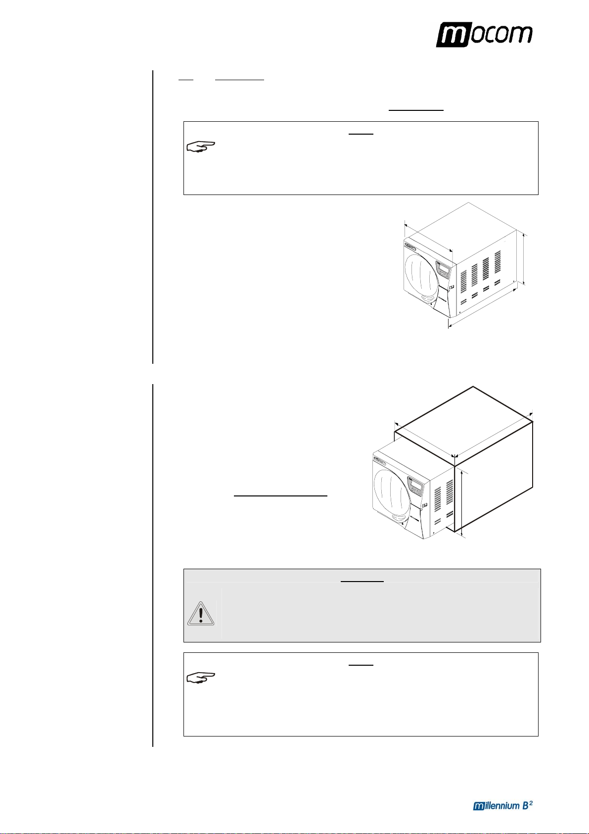
Dimensions and weight
– Height (total) 420 mm
– Width (total) 480 mm
– Depth
(excluding rear connections) 660 mm
– Total weight 63 kg
Electricity
The electrical system to which the sterilizer will be connected must be suitably dimensioned
based on the electrical characteristics of the device. This information is shown on the back of
the machine.
When installing the sterilizer inside a cabinet, you
must provide adequate space all around the device
(>10cm, specially in the rear part) to provide
effective ventilation as well as a large enough
opening in the back that, in addition to allow the
passage of the power cord will also provide an
50
adequate air flow and the consequent optimum
cooling of the heat exchanger.
It is indispensable that the built-in compartment
have the following minimum dimensions
shown in
the figure.
WARNING
COMPARTMENT DIMENSIONS LESS THAN THOSE SHOWN MAY
COMPROMISE THE CORRECT CIRCULATION OF AIR AROUND THE
DEVICE AND MAY NOT PROVIDE ADEQUATE COOLING, WITH THE
CONSEQUENT DETERIORATION OF PERFORMANCE AND/OR POSSIBLE
DAMAGE.
NOTE
IF THE MAIN SWITCH IS INACCESSIBLE WHEN INSTALLED IN THE COMPARTMENT, USE AN
ELECTRIC PLUG THAT INCORPORATES AN ON/OFF SWITCH.
O NOT REMOVE THE UPPER COVER OR ANY OTHER EXTERNAL PART. WHEN INSTALLED
D
IN THE COMPARTMENT
LEASE REFER TO APPENDIX A (TECHNICAL CHARACTERISTICS) FOR COMPLETE
P
TECHNICAL DATA
, THE DEVICE MUST BE COMPLETE WITH ALL ITS PARTS.
.
10
Page 16
4. INSTALLATION
GENERAL
INSTALLATION
PRECAUTIONS
ELECTRICAL
CONNECTIONS
Obey the following warnings for the correct operation of the device and/or to avoid risky
situations:
Install the sterilizer on a flat surface
an irregular surface and to slightly tilt lower the front part of the sterilizer.
Make sure that the support surface is strong enough to support the device's weight (about 65
kg);
– Leave adequate space for ventilation
sterilizer, especially in back.
If the device is built-in to a cabinet, be sure to respect the warnings in the preceding
paragraph, avoiding an obstructions to the air intake;
– Do not install the sterilizer near tubs, sinks or similar places, to avoid
liquids. This could cause short circuits and/or potentially dangerous situations for the
operator;
– Do not install the sterilizer in a place that is excessively humid or poorly ventilated;
– Do not install the machine were there is gas
– Install the device so that the power cord is not
way to the socket.
– Install the device that any external fill/drain tubing is not
freely to the drain tank.
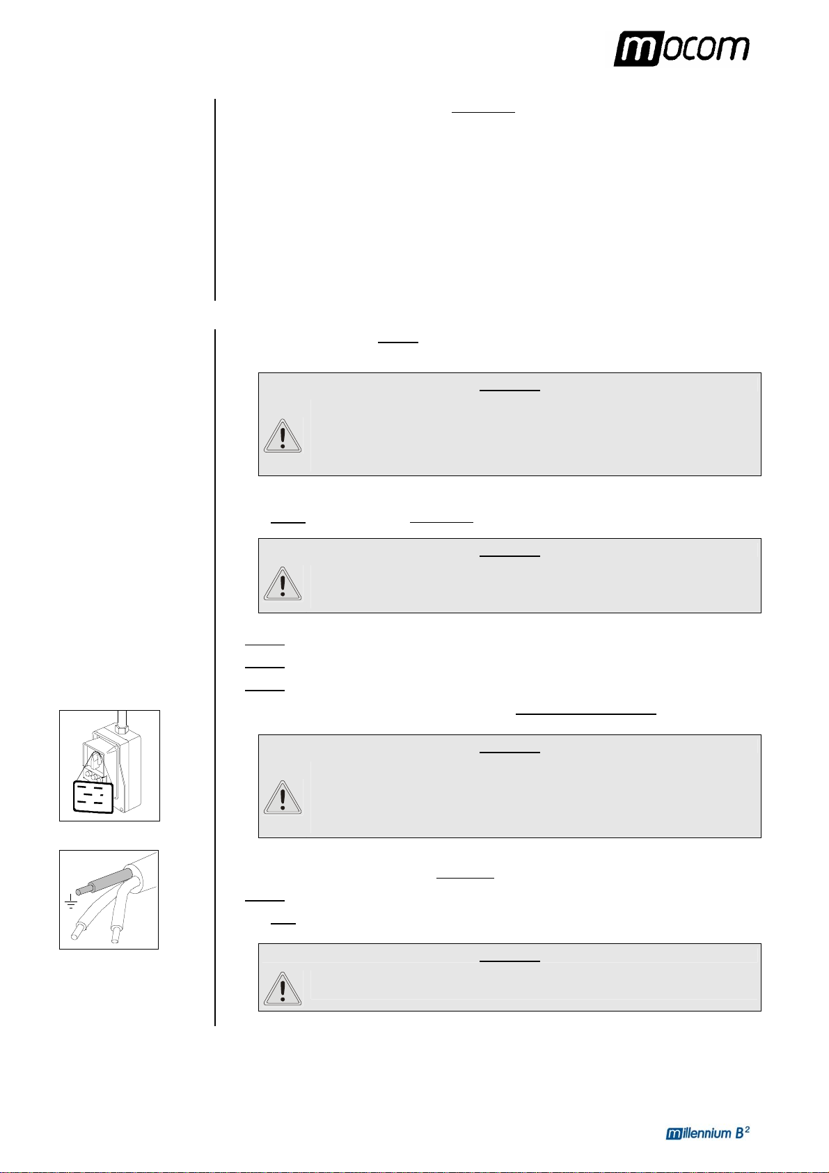
The sterilizer's must be connected to a socket of the electrical system of adequate capacity for
the device's absorption and ground provided, in conformity with current laws and/or standards.
The socket must be suitably protected by a breaker having the following characteristics:
– Nominal current In 16 A
; if necessary, adjust the leveling feet to compensate for
(at least 10 cm on each side) all around the
contact with water or
or inflammable and/or explosive vapors;
bent or crushed. It must run freely all the
bent or crushed. They must run
CONNECTING THE
DATA RECORDING
MILLFLASH
– Differential current I∆n 0.03 A
WARNING
THE MANUFACTURER WILL NOT BE LIABLE FOR DAMAGES CAUSED BY
INSTALLING THE STERILIZER ON AN INADEQUATE ELECTRICAL
SYSTEM AND/OR NOT EQUIPPED WITH A GROUND.
If it is necessary to replace the plug on the power cord, use one with equal characteristics or,
at any rate, adequate to the device's electrical characteristics. The user is entirely responsible
for the selection and replacement of the plug.
NOTE
ALWAYS CONNECT THE POWER CORD DIRECTLY TO THE SOCKET. DO NOT USE
EXTENSION CORDS
The sterilizer can be connected to MILLFLASH allowing the recording of the cycle data on .txt
format file and its management by PC.
The connectors of the service box are used for interfacing; refer to MILLFLASH Operating
Manual for the installation instructions.
, ADAPTERS OR OTHER ACCESSORIES.
11
Page 17
4. INSTALLATION
CONNECTING AN
EXTERNAL
WATER FILLING
TANK
(OPTIONAL, automatic
filling function)
To avoid having to periodically fill the water tank (see Chapter 5, “First Start-Up”), it is
possible to connect the sterilizer to an external filling tank (supplied as an option), that the user
will periodically fill, or to a commercially-available, reverse-osmosis water purification system
with accumulation tank.
In that case, when the internal water tank reaches the MIN level, the autoclave activates a
pump that automatically fills the internal tank.
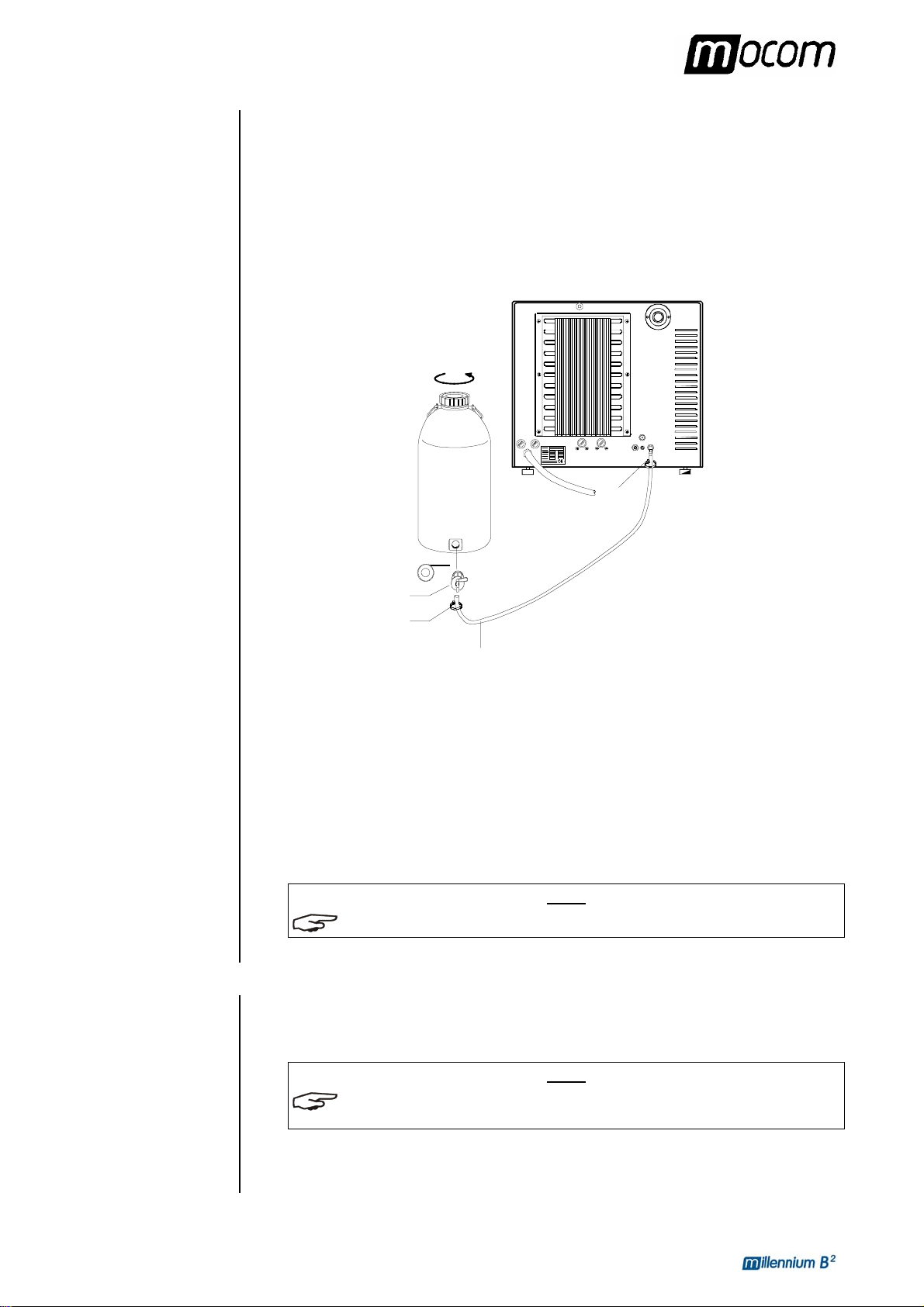
Follow the instructions below for the correct connection of the external tank:
– Install the tap provided on the filling tank; use Teflon tape or connector sealant for a perfect
seal.
Filling
tank
Clip
CONNECTING
DEMINERALIZER
MILLDROP
Teflon
Tap
Clip
Silicon pipe
– Use the filling tanks silicone tube (or other suitable tube, max length 2m) and insert it on
the filling connector taking care to push it completely on.
– Lock the tube to connector with the plastic tie provided.
– Insert the other end of the tube on the tap of the filling tank.
– Make sure that the tube runs freely from the device to the filling tank, without being bent,
crushed or obstructed in any way.
– Loosen the upper plug to facilitate the flow of water (also remove any gasket or under-
plug);
– Open the tap on the filling tank.
NOTE
REFER TO THE CHAPTER, “CONFIGURING THE DEVICE – AUTOMATIC FILLING OPTION ”.
The sterilizer can be connected to MILLDROP (water treatment system by reverse osmosis)
warranting the automatic reservoir filling with high quality demineralized water.
Refer to MILLDROP operating manual for the installation instructions.
NOTE
FOR THIS OPTION SETTING, REFER TO CHAPTER “CONFIGURING THE DEVICE –
AUTOMATIC FILLING OPTION”.
For additional information and advice about the correct connection of the sterilizer to the
various water purification systems, contact M.O.COM. customer support (see Appendix Z).
12
Page 18
4. INSTALLATION
D
R
e
CONNECTING AN
EXTERNAL DRAIN
TANK
OPTIONAL, external
drain function)
Connecting the tank to
a central draining point
An external drain tank (supplied as an option) can be used to avoid having to periodically
empty the internal used water tank, which is then manually emptied or connected to central
drain system.
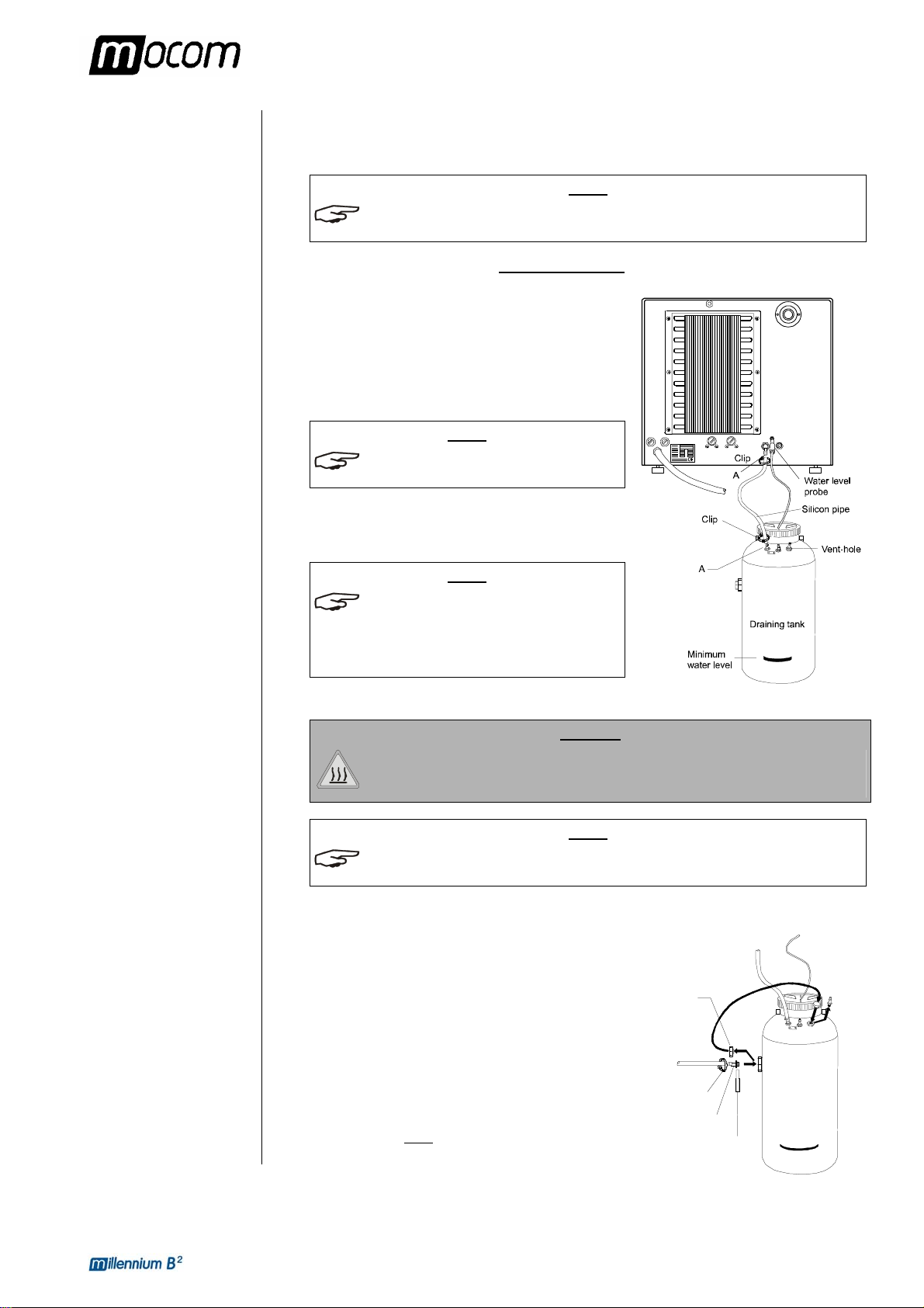
NOTE
CHECK THAT THE DRAIN SILENCER IS CORRECTLY INSTALLED INSIDE THE TANK,
CORRESPONDING TO CONNECTION
“A”.
Follow the instructions below for the correct connection of the tank:
– Insert the silicone tube (provided with the option) on
connector A on the machine; push the tube all the
way on and lock it with the plastic tie;
– Cut the silicone tube to measure, push the free end
on connector A on the drain tank and lock it with the
plastic tie;
NOTE
MAKE SURE THE TUBE IS NOT BENT,
CRUSHED OR OBSTRUCTED IN ANY WAY
.
– Connect the plug of the level sensor to the jack
(optional) on the back of the device (see figure);
NOTE
MAKE SURE THE PLUG IS CORRECTLY
INSERTED
INTERPRETED AS A MAX LEVEL SIGNAL,
WITH A CONSEQUENT ALARM WHENEVER
YOU INSIST ON STARTING THE CYCLE
. A POOR CONNECTIN IS
.
– Fill the tank with normal tap water up to the level marked on the container.
DANGER
HOT WATER AND STEAM UNDER PRESSURE COME OUT OF THE DRAIN
CONNECTORS. CONNECT ALL THE ELEMENTS OF THE DRAIN CIRCUIT
CAREFULLY TO AVOID PROPERTY DAMAGE AND/OR INJURY.
NOTE
FOR THIS OPTION SETTING, REFER TO CHAPTER “CONFIGURING THE DEVICE – SETTING
THE WATER DRAINING MODE
”..
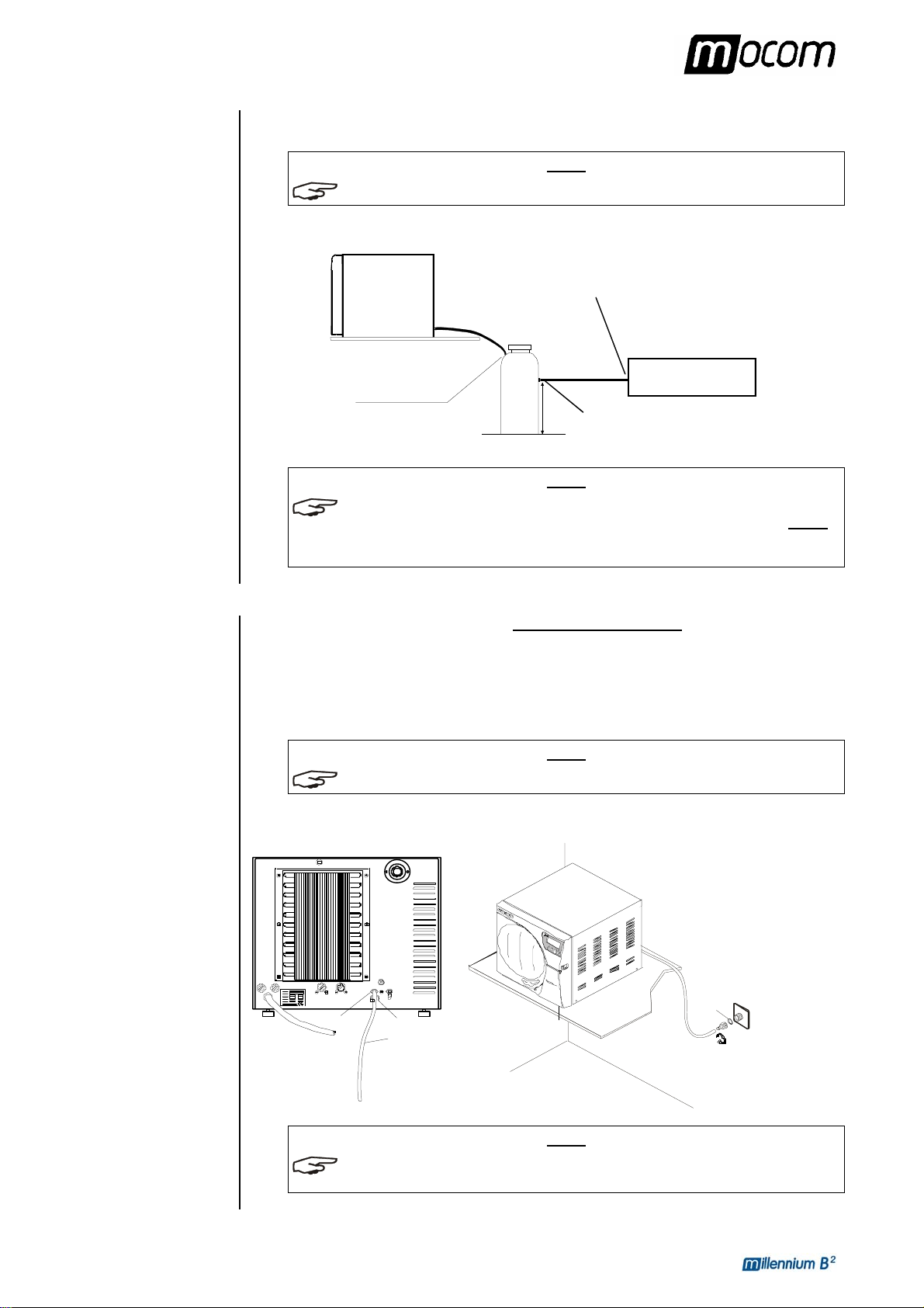
To avoid having to periodically empty the draining tank, it
is possible to connect it directly to a central drain.
– Insert the screw plug in place of the free vent hose
union on the side connector of the draining tank;
Plug
eplace th
pipe-fitting
by the plug
– Screw the 1/8" hose union, supplied, on the side
connector; use a wrench to hold the connector to be
tightened;
– Use Teflon tape or connector sealant for a perfect
seal.
– On this tube union, insert a tube of suitable material
and dimensions (NOT
SUPPLIED); push the tube all
the way on and lock with the plastic tie provided.
To the draining
plant
Clip
Pipe-fitting
raining tank
Teflon
13
Page 19
4. INSTALLATION
DIRECT
CONNECTION TO A
CENTRALIZED
DRAINING POINT
– Connect the other end of the tube to the centralized draining point, checking the seal.
NOTE
MAKE SURE THE TUBE IS NOT BENT, CRUSHED OR OBSTRUCTED IN ANY WAY.
The following diagram provides an indicative arrangement of the components:
Connection point
Sterilizer
Support plane
This point must be lower
than the support pla ne
Draining ta n k
of the centralized draining plant
CENTRALIZED
X
Connection point
of the draining tank
DRAIN
NOTE
DIMENSION X IS THE HEIGHT OF THE SIDE CONNECTOR OF THE TANK ABOVE THE FLOOR.
THE CONNECTION BETWEEN THE TANK AND THE CENTRALIZED DRAINING POINT MUST
NO HIGHER THAN X
EMPTYING OF THE TANK
+30 MM. HIGHER CONNECTIONS COULD COMPROMISE THE CORRECT
.
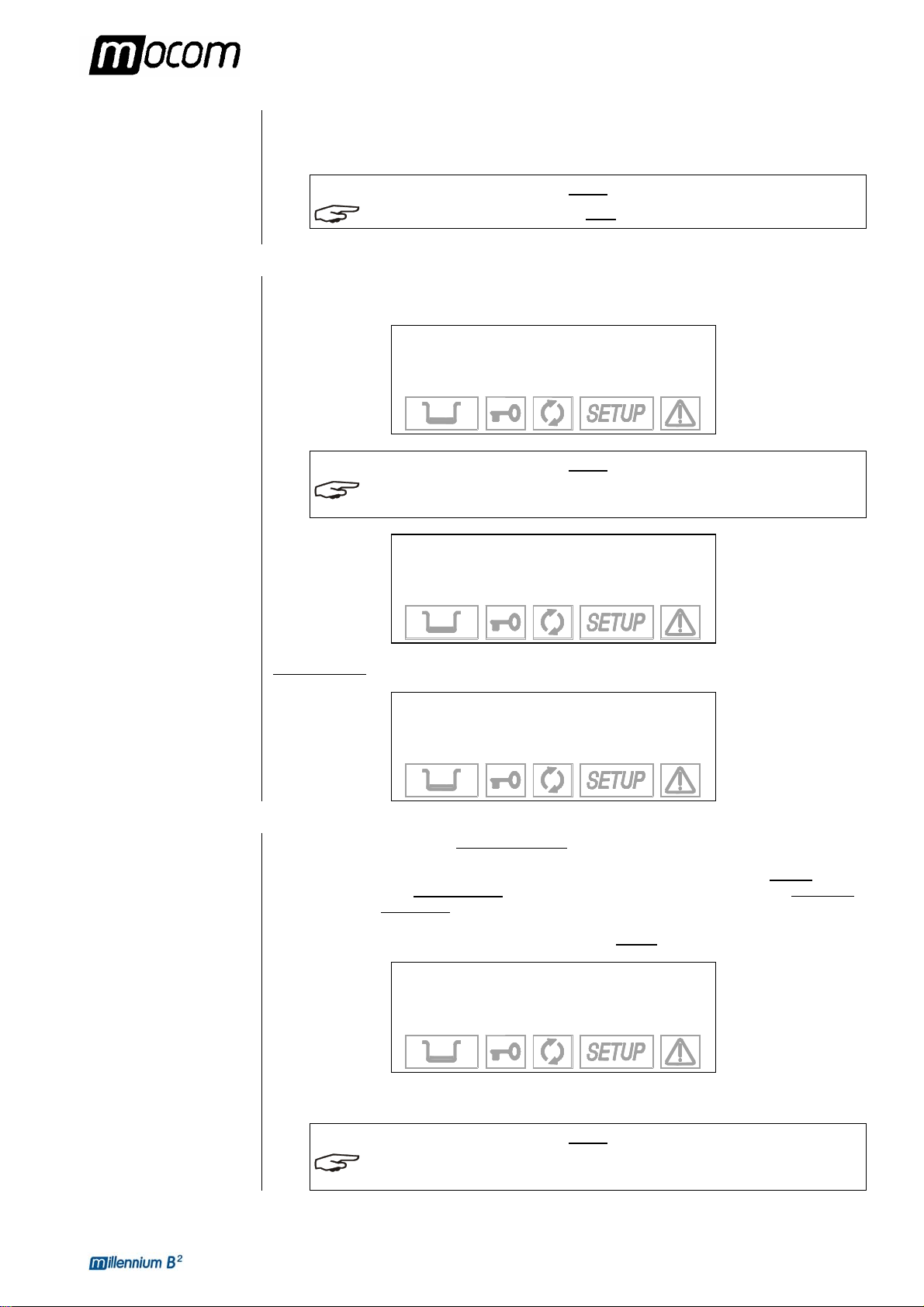
Follow the instructions shown below for a correct direct connection to a centralized draining
point:
– Insert the silicone tube (provided) or other suitable plastic tube on hose union A; push the
tube all the way on and lock with the plastic tie or other means;
– Cut the tube to measure, push the free end on the connection provided on the centralized
draining point and lock with the plastic tie or other means;
NOTE
MAKE SURE THE TUBE IS NOT BENT, CRUSHED OR OBSTRUCTED IN ANY WAY.
The following diagram provides an indicative arrangement of the components:
Centralized
A
Clip
Pipe
To the centralized
draining point
Su pport plane
This point must be at level lower
than the steri l izer’s support plane
Washer
draining point
Clip
NOTE
THE CONNECTION POINT TO THE CENTRAL DRAIN MUST BE LOWER THAN THE
STERILIZER
'S SUPPORT SURFACE. OTHERWISE, THE TANK MAY NOT EMPTY CORRECTLY.
14
Page 20
5. FIRST START-UP
FIRST START-UP
TURNING ON THE
EQUIPMENT
INITIAL
AUTOMATIC
TEST
Once the sterilizer has been correctly installed, it may be turned on and prepared for use.
Turn on the equipment by the main (luminous) switch located on the right side of the machine.
NOTE
DO THIS WITH THE STERILIZER'S DOOR OPEN.
When turned on, the control panel lights up and beeps so you can visually check its correct
operation. The panel then displays this message:
MILLENNIUM B2
R. Exxxx/BGyyyyyy
DEVICE CHECK-UP
NOTE
IF THE DOOR IS CLOSED, THE TEST IS INTERRUPTED. THE PANEL THEN BEEPS AND
DISPLAYS THE FOLLOWING MESSAGE
OPEN DOOR
TO CONTINUE
.
ACQUISITION AND
UPDATING OF THE
AMBIENT
PRESSURE
VALUES
Open the door to allow the test to continue. At the end of the test you will see:
MILLENNIUM B2
R. Exxxx/BGyyyyyy
CHECK-UP COMPLETE
The sterilizer measures the ambient pressure for the correct operation of several auxiliary
devices. Whenever the difference between the value read and that previously stored (see the
Chapter, “Configuring the Device - Acquisition the ambient pressure) is higher than a
set value, the system automatically
the data remains unchanged
After updating, the device performs the initial automatic test procedure (see the preceding
paragraph). At the end, the display shows the following notice (accompanied by a beep):
When ↵ is pressed, the device goes to STAND-BY mode (see the following paragraph).
ALSO SEE THE PARAGRAPH, “ACQUIRING THE AMBIENT PRESSURE VALUE” IN THIS
REGARD
without updating.
AMBIENT PRESSURE
-0.01 bar
↵ to continue
.
updates the stored value after a brief delay. Otherwise,
VALUE UPDATED
NOTE
15
Page 21
5. FIRST START-UP
STAND-BY MODE
After the initial test, the sterilizer goes to STAND-BY mode and the display shows:
Counter xxxxx/yyyyy
Stand-by HIGH
23.6 °C 30/08/02
-0.01 bar 18:13:05
The upper line is the cycle counter for sterilizations performed, with the number of correctly
completed cycles on the left
and the total number started on the right. The line below shows
the Stand-by status and the preheating mode (High-Low-Off). The two lower lines show the
temperature and pressure of the sterilization chamber on the left and current date and time on
the right.
NOTE
A CYCLE BEGINS WITH THE START OF THE STERILIZATION CYCLE (FIRST VACUUM
), EXCLUDING THE PREHEATING PHASE. A CYCLE ENDS AT THE END OF THE
PHASE
PROGRAM
(SEE THE CHAPTER, “PROGRAM EXECUTION”).
O SET THE DATE AND TIME AS WELL AS SELECT THE PREHEATING MODE, PRINT THE
T
DATA AND FILL THE TANK
”.
DEVICE
, PLEASE REFER TO THE CHAPTER, “CONFIGURING THE
At regular intervals, the first two lines on the display alternate with the modes set for printing
(ON/OFF) and filling (Manual/Automatic):
Print ON
Filling MANUAL
23.6 °C 30/08/02
-0.01 bar 18:13:05
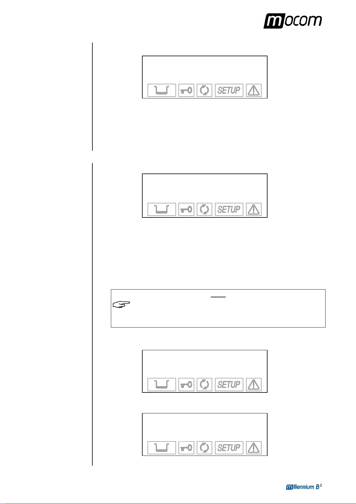
The icons in the lower part of the LCD screen remain off with the exception of the door status
and/or water level indicators, which light-up if the door is closed and/or the level in the filling
tank reaches its MIN or MAX values (or the MAX value in the drain tank).
During the first start-up, the MIN water level icon in the filing tank is normally on.
The device waits for the selection of the desired sterilization program (see the Chapter,
“Program Selection”).
DANGER
WHEN THE DOOR IS OPEN IN STAND-BY MODE, A LONG BEEP OF
ABOUT 30 SEC. INDICATES THAT THE SURFACES INSIDE THE DEVICE
ARE HOT. TO AVOID BURNS, TAKE CARE NOT TO TOUCH THE
STERILIZATION CHAMBER, THE SUPPORTS PROVIDED OR THE INSIDE
OF THE DOOR WITH YOUR BARE HANDS.
16
Page 22
5. FIRST START-UP
FILLING DISTILLED
WATER
Manual filling
Automatic filling
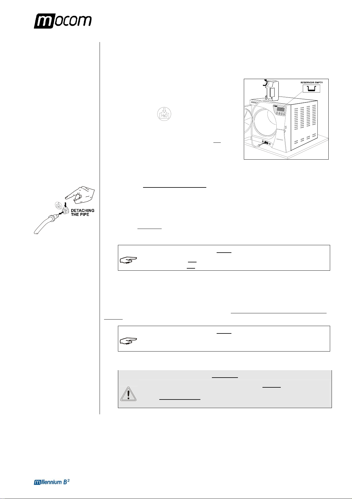
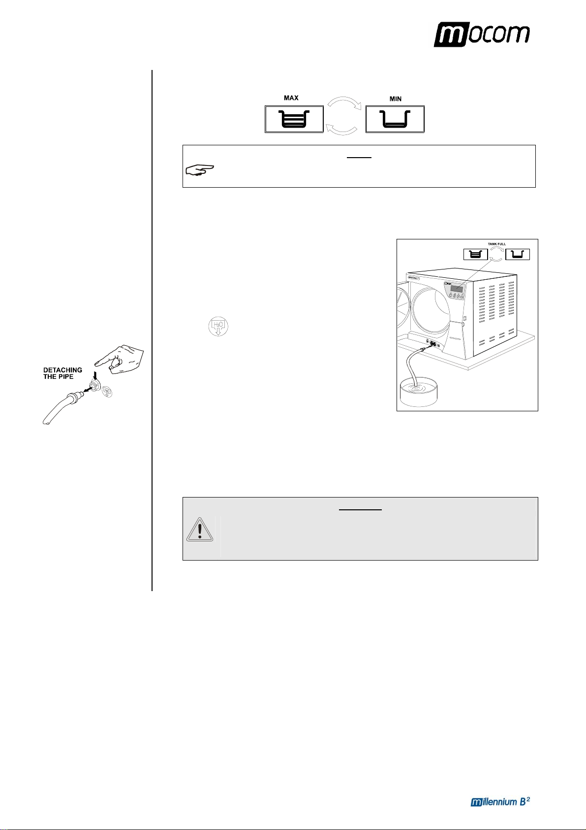
The first time the sterilizer is used, and later when the MIN water level indicator comes on, you
will have to fill, or top-off, the internal distilled water tank.
With reference to the figure (and with the door open), proceed as follows:
1. Fill the manual container (2 l) with distilled water,
keeping it horizontal;
2. Connect the tube’s quick connector to the
corresponding female connector under the chamber
entrance (marked
click;
3. Place the container in a vertical position, at the same
time, loosening the plug and taking care not
water on the machine.
4. The water will begin to flow into the tank;
5. Continue filling until the MIN level indicator turns off.
6. Continue until the water is drained from the container;
7. At this point, lower the connector below
8. While pinching the tube with your fingers, press the metal lever located on the side of the
connector and detach the quick connector;
9. Refill the container (2 l) and repeat the operations described in points 2, 3 and 4 a second
time;
10. W hen the MAX level
quick connector as described in points 7 and 8.
THE ICON MAX DOES NOT HAVE TO BE ON TO START A STERILIZATION PROGRAM. THE
MIN INDICATOR OFF IS SUFFICIENT.
ICON
In the event of sterilizer installation for automatic filling from an external tank or demineralizer
Milldrop (see the Chapter, “Installation”), the filling will occur automatically after the automatic
filling option has been selected.
Obviously, for the correct operation, the user must fill the external tank or switch on the
Milldrop in advance.
USE ONLY HIGH QUALITY DISTILLED WATER. FOR THE SPECIFICATIONS OF THE WATER
SUPPLY
To set the automatic filling option, please refer to the Chapter, “Configuring the Device”.
THE AUTOMATICALLY FILLING SYSTEM MUST NEVER RUN DRY; THIS
CAUSES PREMATURE WEAR TO THE AUXILIARY WATER-INJECTION
PUMP. PERIODICALLY CHECK THE WATER LEVEL IN THE EXTERNAL
TANK.
), pushing until you hear a
to spill
the connection point, keeping it horizontal;
icon comes on (accompanied by a beep), stop filling and detach the
NOTE
NOTE
, SEE APPENDIX A (TECHNICAL CHARACTERISTICS).
WARNING
17
Page 23
5. FIRST START-UP
MAX LEVEL IN THE
INTERNAL/
EXTERNAL DRAIN
TANK
Emptying the internal
tank
Emptying the external
tank (option)
When the water level in the internal or external drain tank reaches the MAX level, the LCD
display alternatively lights the MAX and MIN icons.
NOTE
IN THIS CONDITION THE UNIT WILL GENERATE AN ALARM INDICATION (SEE APPENDIX E -
ALARM) AS YOU ATTEMPT TO LAUNCH A STERILIZATION CYCLE.
In this case, empty the internal or external draining tank.
Referring to the figure, open the door and operate in the
following way:
1. Arrange an empty tank on the floor near the sterilizer
and put the free end of the supplied tube into the tank;
2. Connect the quick connector to the corresponding
female connector under the chamber entrance
(marked
3. Wait for the complete empty of the internal tank; then
while pinching the tube with your fingers, press the
metal lever located on the side of the connector and
detach the quick connector.
Remove the top cap from the external tank and empty into a sink the water exceeding the
signed level.
Refer to chapter “CONNECTING AN EXTERNAL DRAINING TANK” for more details.
), pushing until you hear a click;
WARNING
DO NOT EMPTY THE TANK COMPLETELY, BUT KEEP A QUANTITY OF
WATER UP TO THE MARKED LEVEL. OTHERWISE THE WATER DRAINING
SOUND AND THE STEAM ESCAPE FROM THE VENT-HOLE WILL
INCREASE CONSIDERABLY.
18
Page 24
6. CONFIGURATION
CONFIGURATION
INTRODUCTION
STARTING AND
ENTERING THE
SETUP MODE
MEANING OF THE
KEYS IN SETUP
MODE
Millennium B² offers personalization options never previously seen on any steam sterilizer.
Users may configure the device to meet their own needs. For example, the device's
performance may be adapted on the basis of the type of activity, the type of material to be
sterilized or its frequency of use.
The SETUP program allows selecting from numerous options that users activate through an
intuitive, easy-to-use menu.
NOTE
USE THE SETUP PROGRAM WHENEVER NECESSARY. A CORRECTLY PERSONALIZED
DEVICE PROVIDES THE BEST PERFORMANCE AND THE MOST SATISFACTORY USE
M.O.COM.
PROVIDING SUGGESTIONS OR ADVICE ON THE BEST WAY TO USES THE OPTIONS IN THE
SETUP PROGRAM
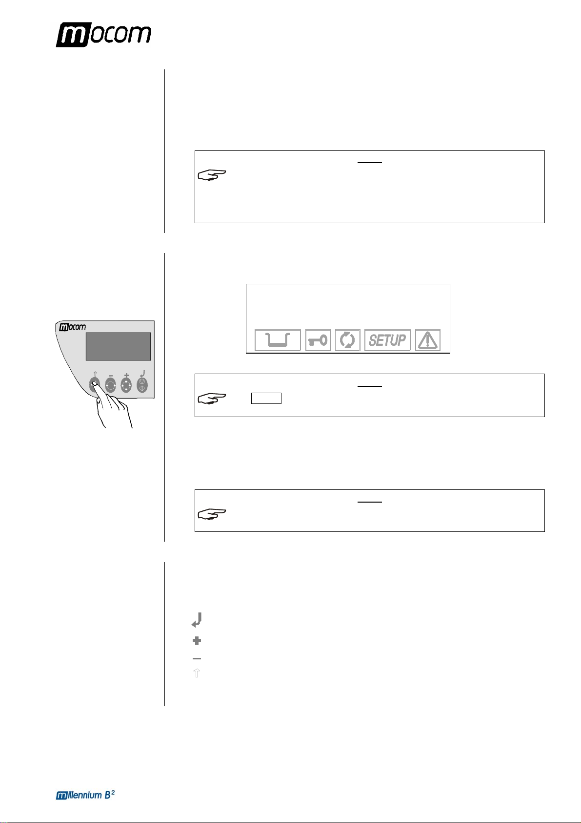
To start the SETUP program, hold down the Ç key on the control panel for several seconds,
until the display shows:
ICON SETUP ON THE DISPLAY LIGHTS-UP AND STAYS ON OR THE ENTIRE
CONFIGURATION PHASE.
When you press the ↵ key, you enter the SETUP mode. The screen shows the first-level menu
items (see the paragraph, SETUP flowchart).
Pressing the ESC key Ç quits the SETUP program and takes you back to normal operation
(stand-by mode).
THE SETUP PROGRAM CAN ONLY BE STARTED IN STAND-BY MODE. IT IS NOT
ACCESSIBLE DURING STERILIZATION OR TEST CYCLES
In SETUP mode the control panel keys have different functions than in normal mode.
Key SETUP mode
CUSTOMER SUPPORT (SEE APPENDIX Z) IS AVAILABLE TO HELP USERS BY
MILLENNIUM B2
SETUP
↵ to continue
Ç to exit
NOTE
NOTE
.
.
function ENTER, confirm the selected option or value
Increase the value /scroll down
Decrease the value /scroll up the menu items
ESC, exit the selected menu option
19
Page 25
6. CONFIGURATION
YES
EXIT
EXTRA
: XX mi n
to enter
MANUAL
EXIT
REPORT
EXIT
NORMAL
PRINT
EXTENDED
EXIT
COPIES
to set to enter
NR
. COPIES
EXIT
INTERNAL
EXTERNAL
EXIT
134c
PROCESS
121c
PROCESS
EXIT
MILLENNIUM B2
NOTES
REPORT
NOW PRINTING
PLEASE WAIT...
SHORT
DRYI N G
LONG
DRYING
EXIT
FRACTION
. VACUUM
SINGLE
VACUUM
EXIT
EXTRA
DRYING
DRYING
REVIEW
PRESSURE VALUE
SET INTO MEMORY
WARNING!
OPEN THE DOOR
Is the door
time
limited
(+ beep)
AMBIENT PRESSURE
EXIT
LCD CONTRAST
CR
TYPE CR
+LF TYPE
EXIT TYPE 1
TYPE 2
EXIT
ACQUISITION OF THE
starting
Firmware
release
Date
dd/mm/yyyy
STANDARD
Stand
by option
Print
option
EXTERNAL
Filling
option
AUTOMATIC
EXIT
REVIEW
to confirm
WRAPPED
EMERGENCY
INTERNAL
AT CYCLE END
EXTERNAL
STEP BY STEP
EXIT
EXIT
TIME
TIME
: XX min
: XX min
to enter
to enter
starting
CR
TYPE (+FF)
CR
+LF TYPE (+FF)
CONFIRM
PASSWORD
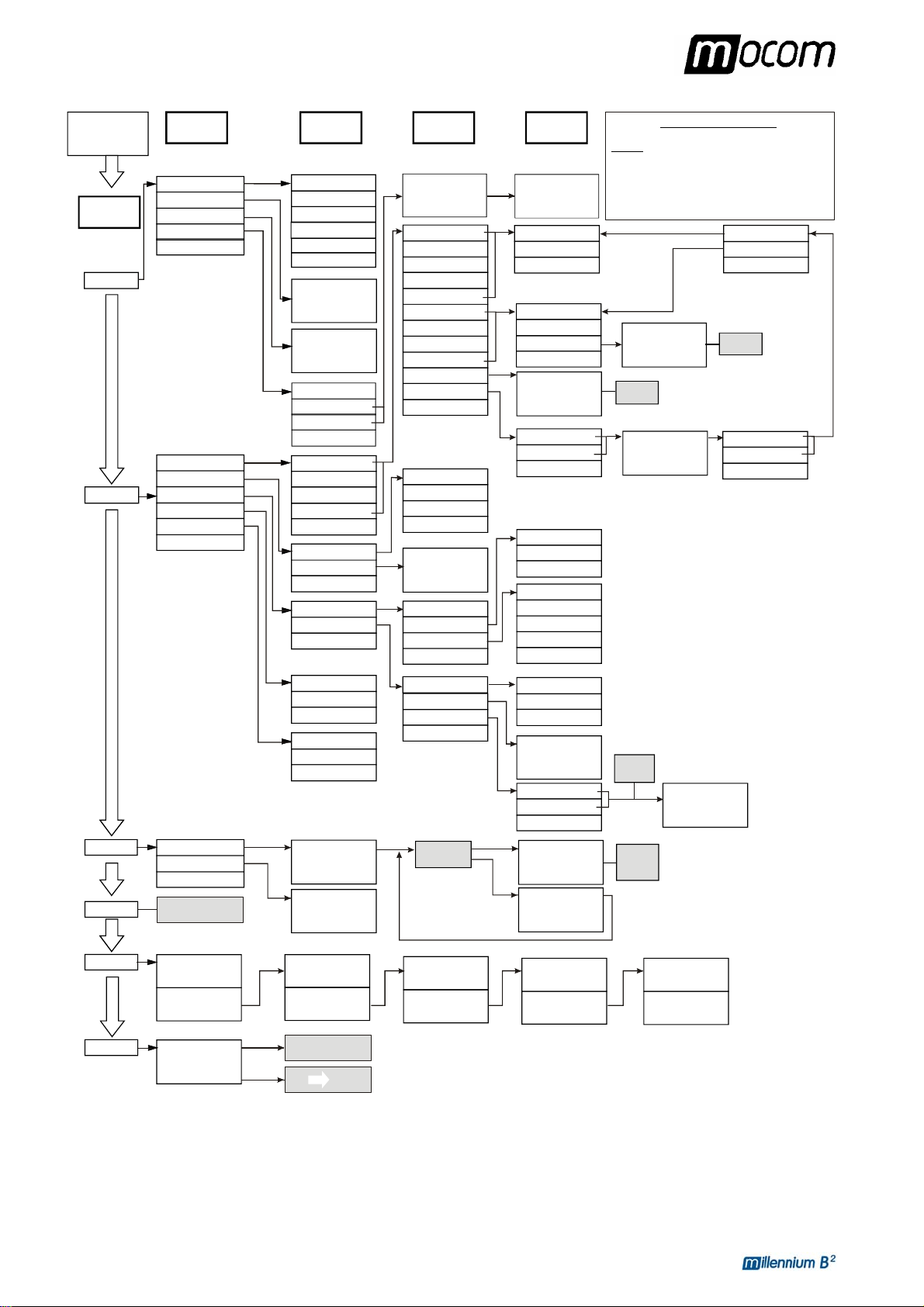
Setup Layout
Selecting the last option of the current menu (or the item
1st MENU LEVEL
MILLENNIUM B2
SETUP
to continue
↵
⇑
to exit
1st MENU
LEVEL
BASIC
ADVANCED
2nd MENU
LEVEL
LANGUAGE
DATE SETTING
TIME SETTING
PASSWORD
EXIT
PROGRAMS
STANDBY OPTIONS
PRINT OPTIONS
FILLING OPTIONS
DRAIN OPTIONS
EXIT
3rd MENU
ITALIANO
ENGLISH
FRANCAIS
DEUTSCH
ESPANOL
EXIT
+/-
to set
to enter
↵
to exit
⇑
+/-
to set
to enter
↵
⇑
to exit
DISABLED
ANY POWER ON
ANY CYCLE START
EXIT
1st PRESET
2nd PRESET
3rd PRESET
4th PRESET
EXIT
ST-BY MODE
ST-BY TIMEOUT
EXIT
PRINTER
LEVEL
dd/mm/yyyy
hh:mm:ss
4th MENU
LEVEL
INSERT PASSWORD
* * * * * * * * * * * * * * *
↵
to enter
⇑
to exit
134c HOLLOW
121c HOLLOW
134c SOLID
121c SOLID
134c EMERGENCY
134c WRAPPED
121c WRAPPED
134c POROUS
121c POROUS
134c PRION
XXXc CUSTOM
EXIT
OFF
LOW
HIGH
TIMEOUT: XXX min
+/- to set
↵
to enter
⇑
to exit
OFF
5th MENU
LEVEL
* * * * * * * * * * * * * * *
↵
to enter
⇑
to exit
STANDARD DRYING
FAST
EXIT
STANDARD DRYING
INTELL. DRYING
EXIT
+/+/-- to set
↵
⇑
to exit
Selecting the item, the previous menu is displayed
ESC
( key has the same effect of EXIT command)
EXIT
TO ENTER), the previous menu is displayed
+/- to set
↵
to exit
⇑
from 18’
to set
↵
⇑
to exit
from 01’
SPECIAL
SERVICE
EXIT SETUP
ONLY AVAILABLE FOR
MOCOM SERVICE
Exxxx / BP yyyyyy
Language
ENGLISH
Time
hh:mm:ss
MILLENNIUM B2
EXIT SETUP?
to confirm
↵
to resume
⇑
+/ to scroll
confirm
resume
AUTOMATIC
AMBIENT PRESSURE
to enter
↵
to exit
⇑
ADJUSTMENT OF THE
LCD CONTR A S T
+/- to set
to exit
⇑
1st PRESET
134c POROUS
DRYING
2nd PRESET
134c HOLLOW
FAST DRYING
EXIT SETUP AND
GO TO STAND-BY MODE
BACK TO
+/to scroll
PRINTOUT MODE
PRINT LAST
open?
3rd PRESET
134c
EXTRA DRYING (+05)
4th PRESET
134c
FAST DRYING
: XX
+/-
↵
⇑
to exit
PRINT
NO
TO CONTINUE
+/to scroll
HIGH
120 min
1 copy
CR+LF
PRINT
THE REPORT
+/to scroll
Drain option
INTERNAL
20
Page 26

6. CONFIGURATION
DESCRIPTION OF
THE MENU ITEMS
Now, we describe the meaning of the various main menu and second-level menu items.
MAIN MENU
The main menu has 6 entries that open additional (second-level) menus:
BASIC (basic options)
ADVANCED (advanced options)
SPECIAL (special options
SERVICE (menu not accessible to users)
DATA REVIEW (summary
EXIT SETUP (exit the SETUP program and return to normal operation. In
this regard, see the paragraph, Exiting the SETUP
program)
THE METHODS FOR CHANGING THE VARIOUS ITEM SETTINGS ARE FOUND IN THE
PARAGRAPH
BASIC Menu
The Basic menu (basic options) consists of the items:
LANGUAGE (language setting
DATE SETTING (setting the current date
TIME SETTING (setting the current time
PASSWORD (setting the password)
EXIT (exit
ADVANCED Menu
The Advanced menu (advanced options) consists of the items:
PROGRAMMES (setting preselected sterilization programs
STAND-BY OPTIONS (stand-by
PRINT OPTIONS (setting printer and printing options)
FILLING OPTIONS (setting modes for filling
DRAIN OPTIONS (setting the modes for emptying
EXIT (exit
SPECIAL Menu
The Special menu (special options) consists of the following items:
AMBIENT PRESSURE (acquisition of the ambient pressure
LCD CONTRAST (adjusting the contrast
EXIT (exit
SERVICE Menu
The Service menu can ONLY
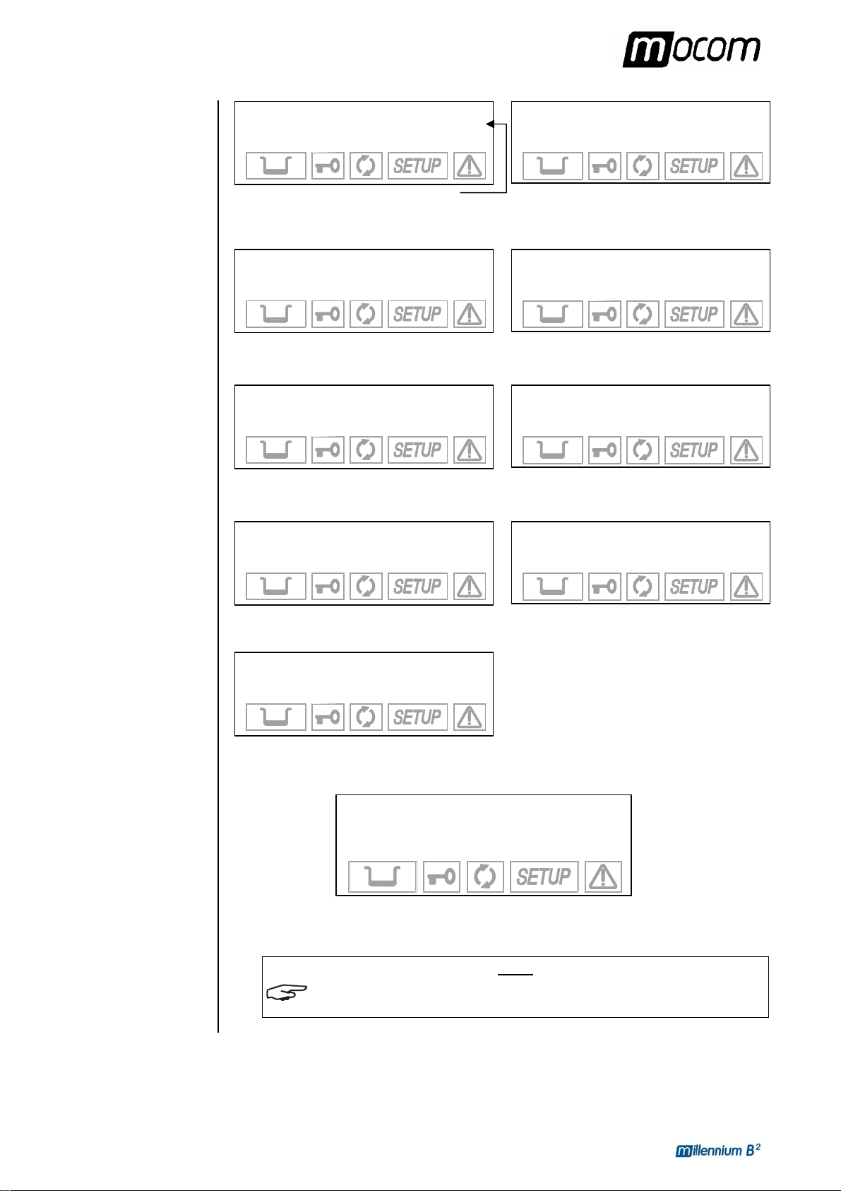
DATA REVIEW Menu
The Data Review displays a summary of the device's current settings
verify their correctness.
It has the following screens (shown by way of example):
, ACTIVATING CONFIGURATION OPTIONS.
the BASIC menu and return to the main menu)
LCD display)
the ADVANCED menu and return to the main menu)
the SPECIAL menu and return to the main menu)
be accessed by the Service department.
)
of options selected)
NOTE
)
);
)
, shown on the
mode settings)
the distilled water tank)
the used water tank)
)
of the Liquid Crystal Display)
, allowing users to
21
Page 27
6. CONFIGURATION
MILLENNIUM B2
R. Exxxx/BGyyyyyy
LANGUAGE
ENGLISH
Firmware version
Use the keys
1st PRESET
134°C POROUS
STANDARD DRYING
Use the keys
3rd PRESET
134°C WRAPPED
EXTRA DRYING +05
Use the keys
Stand-by option
HIGH
120 min
Use the keys
Filling option
AUTOMATIC
Drain option
INTERNAL
Use the keys
EXIT
DATA REVIEW
↵ to continue
DATE
dd/mm/yyyy
TIME
hh:mm:ss
+ / - to scroll through the menu
2nd PRESET
134°C HOLLOW
FAST DRYING
+ / - to scroll through the menu
4th PRESET
134°C EMERGENCY
FAST DRYING
+ / - to scroll through the menu
Print option
INTERNAL
1 COPY(ies)
+ / - to scroll through the menu
+ / - to scroll through the menu
Press ↵ to confirm
NOTE
FOR THE MEANING OF THE TERMS SHOWN, SEE THE PARAGRAPH, ACTIVATING
CONFIGURATION OPTIONS.
22
Page 28
6. CONFIGURATION
DEFAULTS
SETTINGS
ACTIVATING
CONFIGURATION
OPTIONS
Setting the language
(LANGUAGE on the
BASIC Menu)
Setting the date
(DATE SETTING on the
BASIC Menu)
The sterilizer leaves the factory with the following settings:
DATE: current date
TIME: current time
PROGRAMS: Preset 1: 134°C POROUS (standard drying)
Preset 2: 134°C HOLLOW (standard drying)
Preset 3: 134°C SOLID (standard drying)
Preset 4: 134°C EMERGENCY
NOTE
THE PROGRAMS INDICATED SHOULD BE CONSIDERED AS PREFERENTIAL SETTINGS.
HOWEVER, OTHER COMBINATIONS ARE POSSIBLE BASED ON THE DESTINATION MARKET.
ST-BY MODE: HIGH (preheating)
PRINT OPTIONS: INTERNAL
1 copy
FILLING OPTIONS: MANUAL
DRAIN OPTIONS: INTERNAL
Now, we provide a detailed explanation of how to select the various available options,
proceeding in the shown in the previous paragraph.
Select LANGUAGE using the ↵ key. The following screen will appear:
ITALIANO +
→
ENGLISH ↑
FRANÇAIS ↓
DEUTSCH ESPAÑOL
Select the desired language. Move using the + or – keys and confirm using the ↵ key to store
the selection. After the data is confirmed, you return to the second-level menu.
NOTE
AS SOON AS THE SELECTION IS CONFIRMED, ALL THE MENUS OF THE SETUP PROGRAM
WILL BE DISPLAYED IN THE LANGUAGE SET
When DATE SETTING is selected with the ↵ key, you will see:
dd/mm/yyyy
+/- to set
↵ to enter
Ç to exit
.
Proceed as follows:
– The day flashes: set the current date with the + and - keys. Confirm with ↵.
– The month flashes: set the current month with the + and - keys. Confirm with ↵.
– The year flashes: set the current year with the + and - keys. Confirm with ↵.
The date is stored. Once the last confirmation is given, you return to the second-level menu.
23
Page 29
6. CONFIGURATION
Setting the time
(TIME SETTING on the
BASIC menu)
Setting the password
(PASSWORD on the
BASIC menu)
When TIME SETTING is selected with the ↵ key, you will see:
hh:mm:ss
+/- to set
↵ to enter
Ç to exit
Proceed as follows:
– The hours flash: set the current hour with the + and - keys. Confirm with ↵.
– The minutes flash: set the current value with the + and - keys. Confirm with ↵.
The time is stored. Once the last confirmation is given, you return to the second-level menu.
When PASSWORD is selected with the ↵ key, you will see this menu:
DISABLED +
→
ANY POWER ON ↑
ANY CYCLE START ↓
EXIT -
Select DISABLED to use the device freely, without any limitation on operator access.
Select ANY P OWER-ON to protect the machine with a password at the time it is turned-on
(power-on from the main switch).
This makes sure that the machine can only be powered-on by authorized personnel, but
afterwards it can be used by others without limitation.
Select ANY CYCLE START to protect the autoclave with a password to be entered both at
power-on and at the start of every sterilization program.
Only authorized personnel will be able to use it.
NOTE
ENTERING A PASSWORD PROVIDES MORE CONTROLLED USE OF THE PRODUCT BUT, AT
THE SAME TIME, INEVITABLY MAKES IT MORE CUMBERSOME. SO AS NOT TO OVERLY
COMPLICATE USING THE DEVICE
IT IS REALLY NEEDED
.
, WE RECOMMEND ONLY ACTIVATING THIS OPTION WHEN
When the ANY POWER-ON or ANY CYCLE START options are selected, the following
screen is displayed:
INSERT PASSWORD
↵ to enter
Ç to exit
Enter the password with the + and – keys (fixed length, 8 characters).
Confirm with the ↵ key. Then, the following message will appear:
CONFIRM PASSWORD
↵ to enter
Ç to exit
Enter the password again using the + and – keys.
24
Page 30

6. CONFIGURATION
Confirm with the ↵ key.
NOTE
TO CHANGE THE PASSWORD, FIRST SELECT THE DISABLE OPTION, WHICH CANCELS
THE PREVIOUS PASSWORD
, AND THEN SELECT THE ANY POWER-ON OR ANY
CYCLE START OPTION, ENTERING THE NEW PASSWORD AS DESCRIBED ABOVE.
Setting the sterilization
programs
(PROGRAMS on the
ADVANCED menu)
The program setting and their storing in four pre-set positions is achieved in various steps
using several menus in sequence.
Each pre-set position can be associated to a standard or user configurable cycle (CUSTOM).
Let's look at the two cases separately.
To associate a standard program and define several of its parameters, proceed as follows:
1. Select PROGRAMS using the ↵ key; the following menu appears:
1st PRESET +
→
2nd PRESET ↑
3rd PRESET ↓
4th PRESET EXIT
Define the position (1, 2, 3 or 4) to which the sterilization program will be associated using
the + and - keys. Confirm with the ↵ key.
2. From here, you enter the list of available cycles:
134 °C HOLLOW +
→
121 °C HOLLOW ↑
134 °C SOLID ↓
121 °C SOLID -
134 °C EMERGENCY
134 °C WRAPPED
121 °C WRAPPED
134 °C POROUS
121 °C POROUS
134 °C PRION
XXX °C CUSTOM
EXIT
Using the + and - keys, scroll the list until you identify the sterilization program desired.
3. Confirm the selection with the ↵ key.
When the PRION program is selected, you will go to a screen for selecting the sterilization time.
TIME: XX min
+/- to set
↵ to enter
Ç to exit
A value can be set, starting from 18 minutes.
25
Page 31

6. CONFIGURATION
As a function of the choices made, you will go to one of two alternative menus that allow selecting
the type of drying to associate to the selected program.
a) Programs with short drying (HOLLOW, SOLID, EMERGENCY):
→ STANDARD DRYING +
FAST DRYING ↑
EXIT ↓
-
It is possible to select STANDARD mode (the default setting) or FAST (reduced drying,
recommended for light loads). Move using the + and - keys and confirm with the ↵ key.
NOTE
THE EMERGENCY PROGRAM PROVIDES ONLY FAST DRYING.
b) Programs with long drying (POROUS, WRAPPED, EXTRA):
→ STANDARD DRYING +
INTELL. DRYING ↑
EXTRA DRYING ↓
EXIT -
It is possible to select STANDARD (default setting), INTELLIGENT (automatic drying that
adjusts its duration longer or shorter than standard drying on the basis of the volume
and/or quantity and type of load) or EXTRA (drying extended by a selectable value,
recommended for critical loads). Move using the + and - keys and confirm with the ↵ key.
NOTE
WITH LARGE LOADS OR SPECIAL MATERI ALS, THE STANDARD OPTION MAY NOT
PROVIDE A PERFECT RESULT. IN THIS CASE, EXTEND THE DRYING PHASE BY USING THE
EXTRA MODE.
ITH PARTICULARLY COMPLEX TYPES OF LOADS (SUCH AS WRAPPED INSTRUMENTS IN
W
"CONTAINER" FOR STERILIZATION) "INTELLIGENT" DRYING MAY NOT WORK
A
CORRECTLY, WITH WORSE THAN EXPECTED RESULTS. IN THESE CASES, USE THE
STANDARD OR EXTRA OPTIONS, DEPENDING ON THE NEED.
When the EXTRA option is activated, the following screen appears:
EXTRA: XX min
+/- to set
↵ to enter
Ç to exit
which permits setting the duration of extra drying from between 1 and 15 minutes (time to
be added to the STANDARD DRYING time). Set the value using the + and - keys and
confirm the selection with the ↵ key.
NOTE
THE SELECTION CAN BE CHANGED AT ANY TIME BY FOLLOWING THE PROCEDURE
DESCRIBED ABOVE
HENEVER AN IDENTICAL STERILIZATION PROGRAM IS ALREADY PRESENT IN ANOTHER
W
POSITION, THE SELECTION IS NOT ACCEPTED. THE FOLLOWING WARNING APPEARS ON
THE DISPLAY
.
, ALONG WITH A BEEP:
THIS PROGRAM
IS ALREADY PRESET
26
Page 32

6. CONFIGURATION
To define the CUSTOM program to associate to one of the pre-set position (1, 2, 3 or 4)
proceed as follows:
1. Select PROGRAMS, select the program number to which the program is to be associated
(see the previous description) and then select CUSTOM in the next screen; the following
menu appears:
→
134°C PROCESS +
121°C PROCESS ↑
EXIT ↓
-
Select 121 °C to perform a custom program with a sterilization process at 121 °C or 134 °C
for one at 134 °C. Move using the + and - keys and confirm with the ↵ key.
2. You will then go the screen:
TIME: XX min
+/- to set
↵ to enter
Ç to exit
Use the + and - keys to set the duration of the sterilization process and confirm with the ↵
key.
NOTE
THE DURATION OF THE STERILIZATION PROCESS IS VARIABLE FROM 4 TO 30 MINUTES
FOR THE PROGRAM AT 134 °C, AND FROM 20 TO 30 MINUTES FOR THE PROGRAM AT
121 °C.
3. After selecting the time, you go to the menu where you specify the type of initial vacuum:
→ FRACTION. VACUUM +
SINGLE VACUUM ↑
EXIT ↓
-
Select FRACTION. to perform a fractionated vacuum (indispensable for sterilizing hollow
bodies and porous materials), or SINGLE for a single preliminary vacuum phase (solid
instruments). Move using the + and - keys and confirm with the ↵ key.
4. At this point, you come to another menu
SHORT DRYING +
→
where you set the drying mode:
LONG DRYING ↑
EXIT ↓
-
Select LONG drying suitable for porous and/or wrapped loads, or SHORT if you need to
sterilize solid, loose materials (and even hollow so long as not wrapped). Move with the +
and - , confirm with the ↵ key.
27
Page 33

6. CONFIGURATION
5. Depending on the selection (SHORT or LONG) one of two different menus will open (these
menus are the same for the standard cycles), i.e.:
In SHORT mode the following is displayed:
→ STANDARD DRYING +
FAST DRYING ↑
EXIT ↓
-
In LONG mode the following is displayed:
STANDARD DRYING +
→
INTELL. DRYING ↑
EXTRA DRYING ↓
EXIT -
For the choice criteria, refer to the instruction of page 26.
Whenever the CUSTOM program is already present in another position, the selection
is not accepted. The following warning appears on the display, along with a beep:
THIS PROGRAM IS
ALREADY PRESET
NOTE
THE SELECTION CAN BE CHANGED AT ANY TIME BY FOLLOWING THE PROCEDURE
DESCRIBED ABOVE
.
HE LIST OF AVAILABLE PROGRAMS, THEIR SCREENS AND THE CHARACTERISTICS OF
T
STERILIZABLE MATERIALS
(IN RELATION TO THE PROGRAMS) ARE CONTAINED IN
APPENDIX B (PROGRAMS).
CCESS TO A CUSTOM CYCLE DOES NOT REQUIRE A PASSWORD. NONE OF THE
A
COMBINATIONS POSSIBLE IN THE CUSTOMIZATION PHASE CREATE ANY RISKS OR
DANGERS OF INJURY TO THE OPERATOR OR DAMAGE TOT HE DEVICE
.
28
Page 34

6. CONFIGURATION
Setting the STAND-BY
mode
(STAND-B Y OPTIO NS on
the ADVANCED menu)
Based on the equipment's frequency of use, or other considerations, it is possible to select the
heating level during the STAND-BY (preheating) phase and the time beyond which STAND-BY
is deactivated.
When you s elect STAND-BY OPTIONS with the ↵ key, you access the following menu:
ST-BY MODE +
→
ST-BY TIME-OUT ↑
EXIT ↓
-
When you select STAND-BY MODE, an additional menu appears where you can set the
heating level:
→
OFF +
LOW ↑
HIGH ↓
EXIT -
Select HIGH (high preheating level) for intense use or, at any rate, to reduce the wait time
between one cycle and the next to a minimum.
Select LOW (low
preheating) for normal use, since the wait time will be relatively shorter, in
any case.
Select OFF (deactivate
preheating) for occasional use. In this case, the wait time will be longer
(up to about 10-12 minutes for a "cold start").
Move using the + and - keys ; confirm with the ↵ key.
On the other hand, when the ST-BY TIME-OUT option is selected, it is possible to set the time
for deactivating STAND-BY, i. e., how many minutes after the last cycle the heating elements
are turned off.
The following screen appears:
TIMEOUT: XXX
min
+/- to set
↵ to enter
Ç to exit
It is possible to set a value between 0 and 300 minutes (in 30-minute increm ents), after which
the heating elements are turned off (a condition analogous to STAND-BY OFF), avoiding the
useless consumption of electricity.
Set using the + and - keys; confirm with the ↵ key.
NOTE
THIS OPTION IS ALSO ACTIVE WITH STAND-BY OFF. HOWEVER, IN THIS CONDITION
THE TIMER VALUE OBVIOUSLY HAS NO EFFECT SINCE THE HEATING ELEMENTS ARE
TURNED OFF ANYWAY AT THE END OF THE STERILIZATION PROGRAM
.
HEN ANY CYCLE SELECTION KEY (STERILIZATION OR TEST) IS PRESSED, OR THE
W
MACHINE IS TURNED OFF AND ON WITH THE MAIN SWITCH
MODE (HIGH OR LOW) IS IMMEDIATELY REACTIVATED.
, THE ORIGINAL STAND-BY
29
Page 35

6. CONFIGURATION
Setting the printing
mode
(PRINT OPTIONS on the
ADVANCED menu)
Printer model 1
The sterilizer is equipped wi th a printer for recording sterilization program data; it is necessary
to set the parameters required for its proper operation.
1. Select PRINT OPTIONS using the ↵ key and the following menu appears:
PRINTER +
→
REPORT ↑
EXIT ↓
-
Select PRINTER to select the settings for the printer used, or REPORT to set the number
of copies to print and to reprint data from the last program executed.
a) Item PRINTER
The following screen appears:
→
OFF +
INTERNAL ↑
EXTERNAL ↓
EXIT -
Select OFF to deactivate the printing of data at the end of a sterilization (or test) cycle.
Select INTERNAL to enable the thermal printer set inside the front of the sterilizer. In
this case, another menu opens:
→
TYPE 1 +
TYPE 2 ↑
EXIT ↓
-
Printer model 2
Select Type 1 for the model 1 of the printer installed.
Select Type 2 for the model 2 of the printer installed.
If, on the other hand, you choose EXTERNAL, the data will be printed on an external
peripheral. Following this selection, another menu opens:
CR TYPE +
→
CR+LF TYPE ↑
CR (+FF) TYPE ↓
CR+LF (+FF) TYPE EXIT
Activate CR to use printers that advance the paper only on the CR (Carriage Return)
command, or CR+LF for that require the CR+LF (Carriage Return + Line Feed)
commands, or with +FF (Form-Feed) for printers that require the addition of this
command.
NOTE
CONSULT THE PRINTER MANUAL TO DETERMINE THE TYPE OF COMMAND USED. IF THIS
INFORMATION IS NOT AVAILABLE
IDENTIFY THE CORRECT SETTING.
, TRY PRINTING WITH THE VARIOUS OPTIONS TO
30
Page 36

6. CONFIGURATION
b) Item REPORT
The following screen appears:
→ PRINTOUT MODE +
NR. COPIES ↑
PRINT LAST ↓
EXIT -
Select item PRINTOUT MODE to chose the mode the data are printed: The following
options appear:
AT CYCLE END +
→
STEP BY STEP ↑
EXIT ↓
-
Select AT CYCLE END to print the report al the end of the cycle.
Select STEP BY STEP to print the data at each phase of the cycle, as result in the
normal printout (see Examples of printed report in Appendix B).
NOTE
IN STEP BY STEP MODE IS NOT POSSIBLE MORE REPORT COPIES.
HE VACUUM AN D HELIX TEST REPORT PRINT IS CARRIED OUT ONLY IN MODE “AT
T
CYCLE END”.
Activate NR. COPIES to set the number of copies of the cycle report to print at the end
of the program. The following text appears:
COPIES: XX
+/- to set
↵ to enter
Ç to exit
Set the number of copies desired (up to a maximum
of 5). Confirm with the ↵ key.
On the other hand, the selection PRINT LAST reprints the report for the last cycle
executed (whether it terminated correctly or was interrupted by an alarm). The
following screen appears:
→ NORMAL PRINT +
EXTENDED PRINT ↑
EXIT ↓
-
The NORMAL PRINT command activates normal printing (that with salient cycle data
produced at the end of a correctly executed cycle), while EXTENDED PRINT activates
complete printing (including all the data typical of a cycle interrupted by an alarm).
31
Page 37

6. CONFIGURATION
Setting the tank filling
mode
(FILLING OPTIONS on
the ADVANCED menu)
NOTE
IF THE LAST CYCLE COMPLETED CORRECTLY (OR WAS INTERRUPTED BY MANUAL
STOP) IT WILL BE POSSIBLE TO REPRINT IT IN EITHER NORMAL OR EXTENDED
. IF THE LAST CYCLE WAS INTERRUPTED BY AN ALARM (MANUAL STOP
MODE
EXCLUDED
) IT ONLY THE EXTENDED MODE WILL BE AVAILABLE.
Following the reprint command, this message will be displayed:
NOW PRINTING
THE REPORT
PLEASE WAIT...
which will remain on the screen until printing is finished.
The internal tank can be filled either manually or automatically, in the latter case, drawing
water from an external device (tank or demineralizer Milldrop connected to the device- see
Chapter, “Installation”).
After FILL OPTIONS is selected, the following menu appears:
AUTOMAT. FILLING +
→
MANUAL FILLING ↑
EXIT ↓
-
Setting the
water draining mode
(DRAIN OPTIONS from
the ADVANCED menu)
When AUTOMATIC FILL is selected, automatic filling is activated.
In this case, as reached the minimum water level (icon MIN on) in the internal tank, the
equipment enable the auxiliary water feeding pump for a pre-set time or a time needed to
reach the maximum level (icon MAX on).
When the maximum leve l (MAX signal) is reached, the automatic system is deactivated.
NOTE
ONLY ACTIVATE THE AU TOM ATI C FIL LIN G MO DE AFTER THE EXTERNAL TANK HAS BEEN
FILLED WITH HIGH QUALITY DISTILLED W ATER OR THE MIL LDROP H AS BEEN TURNED ON.
ALSO REMEMBER TO OPEN THE TAP ON THE EXTERN AL TANK OR THE MILLDROP.
When MANUAL FILL is selected, the internal tank must be filled manually (see the Chapter,
“First Start-Up”).
Scroll through the items with the + and - keys; confirm with the ↵ key.
The water used for the sterilization cycle can be drained into either the internal
configuration) or an external
tank of greater capacity (offered as an option – see chapter
tank (standard
“Installation”) so as to reduce the frequency of emptying the used wa ter.
After DRAIN OPTIONS is selected, the following menu appears:
→
INTERNAL DRAIN +
EXTERNAL DRAIN ↑
EXIT ↓
-
32
Page 38

6. CONFIGURATION
Acquisition of the
ambient pressure
(AMBIENT PRESSURE
on the SPECIAL menu)
When INTERNAL DRAIN is enabled, the reading of the MAX level sensor in the internal tank
is enabled.
The EXTERNAL DRAIN command also activates the MA X level sensor located in the external
tank.
NOTE
THE LEVEL SENSOR IN THE INTERNAL TANK REMAINS ACTIVE IN ANY CASE, TO PREVENT
A POSSIBLE MALFUNCTION OF THE EXTERNAL TANK OR A MISSING OR FAULTY
CONNECTION OF THE OPTIONAL EXTERNAL DRAIN TANK
N THE CASE OF AN INSTALLATION WITH THE DRAIN CONNECTED TO THE CENTRAL
I
, SELECT INTERNAL DRAIN.
SYSTEM
.
Scroll through the items with the + and - keys; confirm with the ↵ key.
The first time the sterilizer is used and after any reinstallation, the sterilizer must acquire the
ambient pressure.
This operation is necessary
or the correct operation of several of the device's auxiliary
systems.
When AMBIENT PRESSURE is activated, the following screen appears:
ACQUISITION OF THE
AMBIENT PRESSURE
↵ to enter
Ç to exit
NOTE
CHECK THAT THE STERILIZER DOOR IS COMPLETELY OPEN. IF YOU TRY TO ACQUIRE
THE PRESSURE WITH THE DOOR CLOSED
THE FOLLOWING MESSAGE WILL BE DISPLAYED:
OPEN THE DOOR
TO CONTINUE
which remains until the door is opened.
Confirm the acquisition of the data by pressing the ↵ key. This message appears:
PRESSURE VALUE
SET INTO MEMORY
accompanied by a beep. The ambient data pressure has been acquired.
On the other hand, press the
Ç key to cancel the operation.
33
Page 39

6. CONFIGURATION
Adjusting the
contrast of the liquid
crystal display
(LCD CONTRAST on the
SPECIAL menu)
EXIT THE
CONFIGURATION
MODE
The LCD contrast adjustment allow to obtain the screen reading as clear as possible,
compensating different sterilizer positioning or ambient brightness.
When LCD CONTRAST is activated, this screen appears:
ADJUSTMENT OF THE
LCD CONTRAST
+/- to set
Ç to exit
Press the + key increases the contrast while the - key decreases it.
Place yourself in your usual working position and adjust the contrast until the display is as
clear and readable as possible.
Completed the sterilizer configuration, proceed as follows to return in normal mode:
– Go to the first-level menu
(see the SETUP layout).
NOTE
TO RETURN TO THE FIRST LEVEL FROM ANY CURRENT MENU LEVEL, JUST SELECT ITEM
EXIT OF THE CURRENT MENU AND CONFIRM BY ↵ KEY.
A
LTERNATIVELY, YOU CAN PRESS Ç (ESC) KEY ONE OR MORE TIMES.
– Select EXIT and confirm with the ↵ key.
This text appears on the display:
MILLENNIUM B2
SETUP COMPLETE
↵ to exit
Ç to resume
After several seconds, the device returns to normal operation
in STAND-BY mode.
34
Page 40

7. PREPARING THE MATERIAL
PREPARING THE
MATERIAL
INTRODUCTION
TREATING THE
MATERIAL
BEFORE
STERILIZATION
The sterilization process can be considered effective, reliable and repeatable so long as the
material is suitably treated first and then correctly arranged in the sterilization chamber in an
orderly manner.
In fact, it should be emphasized that organic residues or deposits of substances used in
medical practice are the inevitable receptacles of microorganisms and may obstruct contact
between the steam and the walls of the instrument, deactivating, at least locally, the lethal
process that sterilization normally provides.
On the other hand, an incorrect arrangement of the load can make the circulation and/or
penetration of the steam into the material difficult and sometimes impossible with the
imaginable consequences. Even the drying process can be strongly influenced by this factor.
For this reason, below we provide some basic
the user to study the subject further in the most suitable way.
First of all, it should be recalled that, when handling and managing contaminated material, it
is a good idea to take the following precautions
– Wear rubber gloves of adequate thickness;
– Clean your gloved hands with a germicide detergent;
– Always carry the instruments on a tray.
– Never carry them in your hands;
– Protect your hands from contact with any sharp points or edges; this will avoid the risk of
contracting a dangerous infection;
– Immediately remove any article that does not need to be sterilized or that is not capable of
withstanding the proces s;
– Carefully wash your still gloved hands when done handling non-sterile material.
All materials and/or instruments to be sterilized must be perfectly clean, without any type of
residue (deposits of organic/inorganic material, fragments of paper, cotton/gauze pads, lime,
etc.).
IN ADDITION TO CAUSING PROBLEMS DURING STERILIZATION, THE FAILURE TO CLEAN
AND REMOVE RESIDUE CAN DAMAGE
.
ITSELF
An effective cleaning
1. Rinse the instruments under running water immediately
2. Separate metal instruments by type of material (carbon steel, stainless steel, brass,
aluminum, chromium, etc.), to avoid electroly tic oxidation-reduction;
3. Wash in an ultrasound cleaner using a mixture of water and germicidal solution, carefully
following the manufacturer's recommendations.
4. For best results, use a detergent specifically designed for ultrasound washing, with a
neutral pH.
5. After washing, carefully rinse the instruments and make sure that residues have been
completely eliminated
consists of the following:
SOLUTIONS CONTAINING PHENOLS OR QU ATERNARY AMMONIA COM POUNDS CAN C AUSE
CORROSION ON INSTRUMENTS AND THE METAL PARTS OF ULTRASOUND DEVICES.
; if necessary, repeat the washing cycle or clean manually.
TO AVOID THE FORMATION OF LIME SPOTS, RINSE WITH DEIONIZED OR DISTILLED WATER,
IF POSSIBLE
DRYING THE INSTRUMENTS
. WHENEVER VER Y HARD TAP WATER IS USED, WE RECOMMEND ALWAYS
.
suggestions regarding these aspects, leaving
:
NOTE
THE INSTRUMENTS AND/OR THE STERILIZER,
after use;
NOTE
NOTE
35
Page 41

7. PREPARING THE MATERIAL
OK OK
For handles (turbines, contra-angles, etc.), supplement the above with treatment in suitable
dedicated devices that provide effective internal cleaning (occasionally including lubrication).
On the other, as regards textile material
caps and other, carefully wash
ARRANGING THE
LOAD
Follow the instructions below for the most efficient sterilization process, preserve the material
and increase its useful life.
General notes for positioning on trays.
– Arrange instruments made of different
– In the case of instruments not
– In any case, arrange the objects sufficiently distant from each other that they will remain so
– Make sure that all instruments are sterilized in an open
– Position cutting instruments
– Arrange recipients (glasses, cups, test tubes, etc.) resting on their side, or upended, so
– Do not
– Since this value is understood to be the maximum allowed limit
– Do not stack trays or put them in direct contact with the walls of the sterilization chamber.
– Always use the tray support provided.
– To insert and extract trays from the sterilization chamber, always use the extractor
NOTE
THE END OF THE STERILIZATION PROGRAM, REMEM BER TO LUBRI CATE THE IN TE RNAL
HANDLE MECHANISMS USING THE SPECIAL STERILE OIL
PRECAUTIONS
, THE INSTRUMENTS USEFUL LIFE WILL NOT BE REDUCED IN ANY WAY
. BY TAKING THESE
WARNING
CONSULT THE INSTRUCTIONS PROVIDED BY THE MANUFACTURER OF
THE INSTRUMENT/MATERIAL TO BE STERILIZED BEFORE SUBJECTING
IT TO AUTOCLAVE TREATMENT, CHECKING FOR ANY
INCOMPATIBILITIES. SCRUPULOUSLY FOLLOW THE METHODS OF
USING DETERGENTS OR DISINFECTANTS AND THE USAGE
INSTRUCTIONS OF THE AUTOMATIC DEVICES FOR WASHING AND/OR
LUBRICATING THEM.
(or porous, in general), such as smocks, napkins,
and then dry them before treating them in the autoclave.
NOTE
DO NOT USE DETERGENTS WITH A HIGH CONTENT OF CHLORINE AND/OR PHOSPHATES.
DO NOT BLEACH WITH CHLORINE-BASED PRODUCTS. THESE SUBSTANCES CAN DAMAGE
THE TRAY SUPPORTS
THE STERILIZATION CHAMBER
, TRAYS AND ANY METAL INSTRUMENTS THAT MAY BE PRESENT IN
.
metals (stainless steel, tempered steel, aluminum,
etc.) on different trays
or well separated from each other.
made of stainless steel, place a paper sterilization napkin or
a muslin cloth between the tray and the tool, avoiding direct contact
between the two
different materials;
for the entire sterilization cycle;
position;
, (scissors, scalpels, etc.) so they can not come into contact
with each other during sterilization; if necessary, use a cotton or gauze cloth to isolate and
protect them;
avoid pooling water;
load trays beyond their indicated limit (see Appendix A).
, it can be excessive in
some cases, so always use common sense
.
provided.
NOTE
PLACE A CHEMICAL STERILIZATION INDICATOR ON EVER Y TRAY TO INDICATE THAT THE
PROCESS HAS OCCURRED
, WORSE, USING NON-STERILIZED MATERIAL. IF PROCESSING WRAPPED MATERIAL,
OR
PLACE THE INDICATOR INSIDE
: THIS AVOIDS USELESSLY REPROCESSING THE SAME LOAD
ONE OF THE WRAPPINGS.
36
Page 42

7. PREPARING THE MATERIAL
OK OK
Notes for rubber and plastic tubing
– Always rinse before use with pyrogen-free water; do not dry them;
– Arrange the tubing on the tray so that their ends are not obstructed or crushed.
– Do not bend or wind them, but allow them to lie as straight as possible.
Notes for packets and packages
– Arrange packages side-by-side, suitably spaced and absolutely not
piled, to avoid their
coming in contact with the walls of the chamber.
– Whenever it is necessary to wrap particular objects, always
use suitably porous material
(sterilization paper, muslin napkins, etc.), closing the wrapping with autoclave adhesive
tape.
Notes for wrapped material
– Wrap instruments individually
wrapping, make sure that they are made of the same metal
– Seal the wrapping with adhesive tape
or, when more than one instrument are placed in the same
;
for autoclaves or heat-sealing machines.
– Do not use staples, pins or other fasteners since they can compromise the maintenance of
sterility;
– Arrange the envelopes so as to avoid forming air pockets that obstruct the correct
penetration and removal of the steam.
– Orient the envelopes so as to leave the plastic side up and the paper side down (tray
side).
– In any case, check that they are correctly positioned, turning them over
– If possible, place the envelopes edgewise
– Never
superimpose envelopes on top of each other.
to the tray, with a suitable support.
, if necessary.
WARNING
WHENEVER YOU ANTICIPATE PROLONGED STORAGE, ALWAYS WRAP
THE INSTRUMENTS. SEE THE CHAPTER, “PRESERVING STERILIZED
MATERIAL”.
37
Page 43

8. PROGRAM SELECTION
PROGRAM
SELECTION
INTRODUCTION
PROCEDURE
Program selection is fundamental
Since each instrument, or material in general, has different shape, consistency and properties,
it is important to identify the most suitable program for it
characteristics (avoiding or, at any rate, limiting alterations) as well to guarantee the most
effective sterilization.
A GUIDE TO SELECTING THE MOST SUITAB LE PROGRAM FOR THE LOAD IS PROVIDED IN
APPENDIX B (PROGRAMS).
Power-on the device as described in the Chapter, “First Start-Up”.
IF A PASSWORD HAS BEEN ENABLED (SEE THE CHAPTER CONFIGURATION - SETTING
THE PASSWORD
↵ to enter
Ç to exit
Enter the password using the + and – keys. Confirm with the ↵ key.
The display does not offer any active preselection.
The device is waiting for the user to select
Press the PROGRAM SELECTION key one or more times until you reach the desired
program (1, 2, 3 or 4, also shown on the upper left of the display).
WHEN THE SELECTION KEY IS PRESSED, THE FIRST STERILIZATION PROGRAM PROPOSED
IS THE ONE USED FOR THE LAST CYCLE EXECUTED
In the two lines above the description, the display shows the description
program and the type of drying set and, below, the set-point values for the temperature (°C),
pressure (bar) and time (mm:ss) of the cycle selected. By way of example, the display shows:
1 134°C POROUS
134.0 °C (B)
2.10 bar 04:00
After a brief interval, the display changes and shows the temperature and pressure values of
the chamber, with the current date and time.
1 134°C POROUS
101.0 °C 30/08/02
0.01 bar 18:13:05
for a successful sterilization process.
, both for preserving its physical
NOTE
NOTE
), YOU WILL BE ASKED TO ENTER THE ACCESS CODE:
INSERT PASSWORD
a program.
NOTE
.
NORMAL DRYING
NORMAL DRYING
of the selected
To cancel the selection, press ESC Ç on the control panel.
38
Page 44

8. PROGRAM SELECTION
NOTE
IF NO STERILIZATION PROGRAM IS SELECTED, THE EQUIPMENT CANNOT START A
STERILIZATION CYCLE
:
A BEEP
, AND THE FOLLOWING MESSAGE APPE ARS ON THE DISPLAY, WITH
SELECT A PROGRAM
PLEASE...
WARNING
IF YOU USE A PROGRAM THAT IS INAPPROPRIATE FOR THE TYPE OF
MATERIAL TO BE STERILIZED (SEE APPENDIX B) THE EFFECTIVENESS
OF THE STERILIZATION PROCESS IS NOT GUARANTEED.
39
Page 45

9. RUNNING THE PROGRAM
RUNNING
THE CYCLE
INTRODUCTION
STARTING THE
CYCLE
Password check
Printer paper-out check
If Millflash is connected
A sterilization cycle consists of a determined number of phases. The number and duration of
the phases can differ for the programs, based on the type of air extraction, sterilization process
and drying method.
The electronic control system monitors the various phases, at the same time checking that the
various parameters are respected; if any type of anomaly is encountered during the cycle, the
program is immediately interrupted, generating an alarm identified by a code, with a relative
message explaining the nature of the problem.
With this type of control, when you select a suitable sterilization program, you are guaranteed
perfect sterilization under any conditions.
After placing the load in the sterilization chamber (with the precautions explained in the
Chapter, “Preparing the Material”) and selecting the desired program, close the door until
you hear the click.
The door status icon
Press the START button.
IF A PASSWORD HAS BEEN ENABLED WITH THE OPTION ANY CYCLE START (SEE THE
Enter the password using the + and – keys. Confirm with the ↵ key.
The equipment checks the presence of the paper into the on-board printer; if out or ended the
following message will be displayed:
Push key ↵ to continue however (replace the paper during or at the end of the sterilisation
cycle).
Push key Ç to return in Stand-by mode.
Depending on the type of the device connected, the equipment checks the presence of the
Compact Flash card. If not plugged in, the display shows:
CHAPTER CONFIGURATION - SETTING THE PASSWORD), YOU WILL BE ASKED TO ENTER
THE ACCESS CODE
flashes (door closed).
NOTE
:
INSERT PASSWORD
↵ to enter
Ç to exit
WARNING
PAPER OUT
↵ to continue
Ç to exit
WARNING
CF CARD MISSING
↵ to continue
Ç to exit
Plug in the CF card in the recording device and press the key ↵ on the command panel.
Push the key Ç to interrupt the start command and return in Stand-by mode.
40
Page 46

9. RUNNING THE PROGRAM
Door locking
In case of the memory full or insufficient to store the new cycle data, the following message
will be displayed:
WARNING
CF CARD FULL
↵ to continue
Ç to exit
or
WARNING
MEMORY FULL
↵ to continue
Ç to exit
Push key ↵ to continue without recording the cycle data.
Push key Ç to interrupt the start command; download the files on PC and delete the memory
content according to the instructions of the Millflash Operating Manual.
Repeat the Start command.
The equipment locks the door.
The door status icon
When START is pushed, and for the entire sterilization cycle
show the following parameters:
Pressure of the sterilization chamber (bar)
Temperature of the sterilization chamber (°C)
Progressive time of the sterilization cycle (mm:ss)
remains steady on
1 134°C POROUS
WARMUP
101.9 °C
0.01 bar 00:00
(door locked).
, the lower lines of the display will
PROGRAM
EXECUTION
Preheating
The time is counted from the start of the sterilization cycle (first vacuum phase), excluding the
preheating phase.
Now, we will analyze the execution of a sterilization cycle, phase by phase.
For our example, let's take the most complete
POROUS, which is characterized by a fractionated pre-vacuum.
When the START button is pressed, the first phase is PREHEATING, which brings the
chamber to temperature required for starting the cycle. The display shows the following:
1 134°C POROUS
WARMUP
23.9 °C
0.01 bar 00:00
The icon that shows the status of the sterilization process
41
and important cycle, i.e., the program 134 °C
is off.
Page 47

9. RUNNING THE PROGRAM
First vacuum phase
First rise in
pressure
Second vacuum phase
Second rise in
pressure
Third vacuum phase
When the optimum temperature is reached, the first vacuum phase (1st VACUUM PULSE) is
started and brings the chamber pressure down to the established value. The display shows:
1 134°C POROUS
1. VACUUM PULSE
84.1 °C
-0.69 bar 01:25
When the pre-set vacuum value is reached, steam is injected and the pressure begins to rise
(1st PRESSURE PULSE), until the established value is reached.
1 134°C POROUS
1. PRESSURE PULSE
108.0 °C
0.47 bar 03:58
At the end of the pressure rise, the steam, mixed with residual air, is discharged and the
second emptying of the sterilization chamber begins (2nd VACUUM PULSE).
1 134°C POROUS
2. VACUUM PULSE
93.3 °C
-0.79 bar 06:06
After the second vacuum phase, steam is again injected into the sterilization chamber, with a
relative rise in pressure (2nd PRESSURE PULSE).
1 134°C POROUS
2. PRESSURE PULSE
11.4 °C
0.72 bar 07:44
The icon that shows the status of the sterilization process
is always off.
At the end of the second pressure rise, there is another discharge and the last vacuum phase
begins (3rd VACUUM PULSE).
1 134°C POROUS
3. VACUUM PULSE
89.9 °C
-0.80 bar 09:52
42
Page 48

9. RUNNING THE PROGRAM
Third rise in
pressure
Thermodynamic
equilibrium
Sterilization
time
Steam discharge
After the last vacuum phase, the pressure in the sterilization chamber must rise to the value
set for the sterilization process (3rd PRESSURE PULSE), always through the injection of
steam.
1 134°C POROUS
3. PRESSURE PULSE
128.6 °C
1.70 bar 12:33
When the pressure and temperature values for the selected program have been reached, it is
a good idea to wait a moment to allow the temperature in the chamber and the load to stabilize
(EQUILIBRATION). The liquid crystal display shows:
1 134°C POROUS
EQUILIBRATION
135.4 °C
2.15 bar 13:40
When the thermodynamic parameters are balanced, the actual sterilization phase of the
materials begins (HOLDING TIME).
Thanks to continuous monitoring of the thermodynamic parameters and sophisticated
management of the plumbing circuit, the pressure and temperature are maintained constant
within the limits required by the program. A countdown begins of the sterilization time. The
display shows the following:
1 134°C POROUS
HOLDING TIME
135.6 °C 04:00
countdown
2.16 bar 13:55
The icon for the sterilization process status flashes to indicate that the treatment of the
load is in progress.
At the end of the sterilization phase, the icon
remains steady on
to indicate the complete
sterilization of the material in the sterilization chamber.
WARNING
IF, FOR SOME REASON, THE STERILIZATION CYCLE HAS BEEN
INTERRUPTED BEFORE COMPLETION, THE ICON CONTINUES
FLASHING.
IN THIS CASE, THE MATERIAL CANNOT BE CONSIDERED STERILE AND
MUST ABSOLUTELY NOT BE USED.
At the end of the sterilization phase, the steam is released from the sterilization chamber
(STEAM DISCHARGE). The liquid crystal display shows:
1 134°C POROUS
DEPRESSURIZATION
123.9 °C
1.24 bar 18:20
The icon for the sterilization process status
is steady on.
43
Page 49

9. RUNNING THE PROGRAM
EXTRA DRYING
set
Drying
Ventilation
Leveling to the
atmospheric pressure
Completion
of the cycle
After the steam under pressure is released, its forced removal begins with the vacuum pump
(DRYING): for this purpose, low pressure is created in the sterilization chamber to facilitate the
evaporation of the steam and its consequent elimination. As a function of the type of drying
set, one of the following screens will appear:
1 134°C POROUS
DRYING (NOR)
Standard drying
101.1 °C
0.00 bar 18:51
1 134°C POROUS
DRYING (INT)
Intelligent drying
101.1 °C
0.00 bar 18:51
1 134°C POROUS
DRYING (+XX)
101.1 °C
(+XX) is the time
0.00 bar 18:51
When the drying phase is finished, it is followed by a VENTILATION phase in which fresh
sterile air is injected, while maintaining a vacuum in the chamber, to eliminate condensate and
cool the load.
1 134°C POROUS
VENTILATION
84.4 °C
-0.77 bar 26:51
At the end of the ventilation phase, the chamber is brought back to atmospheric pressure
(LEVELLING) by injecting sterile outside air to allow the opening of the door and the retrieval
of the load.
1 134°C POROUS
LEVELLING
86.9 °C
-0.43 bar 29:21
When the pressure in the sterilization chambers returns within the pre-set safety limits, the
door lock system is released.
As a consequence, the door status indicator flashes. At the same time, it also beeps.
1 134°C POROUS
CYCLE COMPLETE
86.2 °C
-0.02 bar 29:40
44
The icon for the sterilization process status
is steady on.
Page 50

9. RUNNING THE PROGRAM
Open the door
Report print
Equipment ready
RESULT OF THE
CYCLE
NOTE
AT THE END OF THE CYCLE, AND UP TO THE OPENING OF THE DOOR, THE HEATING
ELEMENTS ARE OFF
REGARDLESS OF WHAT THE
. AS A CONSEQUENCE, THE DEVICE IS SLOWLY COOLING
STAND-BY MODE IS.
NOTE
WHENEVER THE STERILIZER'S' DOOR IS NOT OPENED AT THE END OF THE CYCLE, THE
VACUUM PUMP IS PERIODICALLY
FROM THE STERILIZATION CHAMBER
ACTIVATED TO REMOVE ANY TRACES OF CONDENSATE
. THE DISPLAY SHOWS:
FORCED VENTILATION
Ç to stop
35.2 °C
-0.02 bar 29:40
Press Ç to interrupt ventilation and open the door.
the door and retrieve the sterilized material, using the extractor provided.
Open
The icon
symbol goes off.
When the door is opened, the device goes to STAND-BY mode as previously set.
When the door is opened, the report for the sterilization cycle executed is automatically
produced. Check the document, initial it in the space provided and file it in a suitable place.
Refer to the print report examples shown in Appendix B, Programs.
NOTE
IF SELECTED THE PRINTOUT STEP BY STEP OPTION, THE REPORT WILL BE PRINTED
DURING THE PHASES OF THE CYCLE
.
The device is ready
to execute a new cycle.
Repeat the procedures explained in the Chapter, “Program Selection” for executing a new
sterilization cycle.
After the cycle is finished, it is important to check the sterilization results.
Whenever a cycle finishes (message CYCLE COMPLETE and icon
on ), without,
therefore, being interrupted by any type of alarm, you are guaranteed to have completely
aseptic material.
The report of the sterilization parameters is an additional check tool.
45
Page 51

9. RUNNING THE PROGRAM
> 3s
CHECK OF THE
CYCLE DATA
REPORT
MANUAL CYCLE
INTERRUPTION
However, it is a good practice to check that the print report issued at the end of the sterilization
program, also specifies a positive outcome.
At the end of the cycle, the salient data for the thermodynamic parameters of the sterilization,
temperature and pressure (°C and bar), and time (minutes) of the sterilization cycle, with
particular attention to the sterilization phase true and proper, is printed by simply opening the
door.
So, check the values on the print report and any additional indications for a further
confirmation of the good outcome of the sterilization process.
The operator should sign in the space provided and file the document for possible future use.
If necessary, copies of the document can be used to identify the load (or parts of it) with the
date/time of sterilization and details of the type of cycle performed.
To select the number of copies to print, consult Chapter 6
NOTE
THE OPERATOR CAN ALSO REQUEST AN EXTENDED PRINTOUT OF THE STERILIZATION
PROCESS DATA
ON THE MACHINE. TO START THIS PRINT FUNCTION, HOLD DOWN THE Ç (ESC) KEY ON
THE CONTROL PANEL WHILE OPENING THE DOOR
OR COMPLETE DETAILS ABOUT PRINTING THE SUMMARY, PLEASE REFER TO THE
F
REPORT EXAMPLES SHOWN IN
The operator can manually interrupt the cycle at any time by pressing the START/STOP key
for three seconds.
The command generates the error E999
consequence, until safe conditions are reached, the display shows, along a beep:
101.2 °C E999
-0.47 bar 26:01
, INCLUDING THE RECORDED VALUES OF ALL THE SENSORS INSTALLED
APPENDIX B, PROGRAMS.
, given that the cycle did not finish correctly. As a
MANUAL STOP
LEVELLING...
, Configuring.
.
Error code
When safe condi tion s are re ache d, the machi ne acti vates a spec ial pro cedure
user to manually unlock the door by displaying the following instruction:
PRESS Ç TO
UNLOCK THE DOOR
86.2°C E999
-0.02 bar 26:01
Press the Ç key to unlock the door.
The following message is then displayed:
MANUAL STOP
OPEN THE DOOR
85.8°C E999
-0.01 bar 26:01
, first ask ing t he
46
Page 52

9. RUNNING THE PROGRAM
> 3s
Finally, when the door is opened, you will be asked to reset the device by the following
message:
MANUAL STOP
RESET SYSTEM
85.5°C E999
-0.01 bar 26:01
To RESET the system, hold down, for at least three seconds,
the PROGRAM SELECTION
key until you hear the confirming beep.
When the door is opened, the report for the sterilization cycle executed is produced, including
the error code (E999). Check the report, initial it in the space provided and file it in a suitable
place.
Refer to the print report examples shown in Appendix B
, Programs.
After the RESET, the device goes to STAND-BY mode, ready to execute a new program
.
NOTE
WHENEVER AN ALARM IS GENERATED IN CERTAIN PHASES OF THE CYCLE, AN
AUTOMATIC PROCEDURE IS ACTIVATED TO CLEAN THE PLUMBING CIRCUIT
COMPLETE DESCRIPTION OF THE ALARMS
, SEE APPENDIX E “ALARMS”.
. FOR A
WARNING
AFTER A PROGRAM IS MANUALLY INTERRUPTED (MANUAL STOP)
ALWAYS CHECK THE STATUS OF THE ICON
BEFORE USING THE
MATERIAL IN THE STERILIZATION CHAMBER.
IF THE ICON
IS STEADY ON, THE MATERIAL IN THE STERILIZATION
CAN BE CONSIDERED STERILE AND, THUS, BE USED. WE RECOMMEND
USING IT IMMEDIATELY.
HOWEVER, IF IT IS OFF, THE MATERIAL IN THE STERILIZATION
CHAMBER CANNOT BE CONSIDERED STERILE AND ABSOLUTELY MUST
NOT BE USED.
47
Page 53

10. STORING STERILIZED MATERIALS
STORING
STERILIZED
MATERIALS
INTRODUCTION
HANDLING
STORAGE
The sterilized material must be adequately treated and stored to maintain its sterility over time,
until its use.
Inadequate storage can
This leads to problems regardless of what you do since you will either be using
recontaminated material (most of the time unconsciously), placing the user and patient at risk,
or you will have to run the sterilization cycle again, with an inevitable waste of time and
resources.
For this reason, we think it will be useful to provide several basic suggestions, leaving the
operator the task of further study of specific texts.
Assuming that the sterilizer is located in a clean place, free of dust and not too damp, the
following precautions should be taken when handling
1. Remove the load from the sterilization chamber wearing gloves
better, sterilized smock
2. Rest the tray on a dry, suitably clean and disinfected surface. Take care to distance or, at
any rate, separate the sterile material from the area where contaminated material is kept
waiting to be sterilized;
3. Touch the material and/or instruments as little as possible, taking extreme care not
or damage
4. Let the instruments cool
transport, transfer the material using dry, clean and disinfected containers. The containers
must be closed
Sterile material waiting for used must be stored using the appropriate techniques. These will
significantly slow recontamination:
1. Store the material and/or instruments in the protective wrappings that were used during
sterilization. Do not
useless and completely senseless, is also potentially damaging;
2. Store the material in a dry
infected material passes. If possible, use closed compartments equipped with ultraviolet
light;
3. Identify the sterile material by attaching the sterilization data (attaching a copy of the
printed report or an adhesive label);
4. First use the material that has been stored the longest (FIFO, "First In First Out"). This
results in material that is homogeneously stored
consequent risks.
5. Never
degrade and be recontaminated in a finite time, even when the above instructions are
followed.
the wrappings;
store material for too long. In fact, do not overlook the fact that materials will tend to
CONSULT THE SPECIFICATIONS PROVIDED BY THE MANUFACTURER OF THE PACKAGING
MATERIAL RELATIVE TO THE MAXIMUM ALLOWED STORAGE TIME
cause rapid recontamination.
and/or carrying sterile material:
and a clean, or even
. As an additional precaution, wear a protective mask on your face;
to cut
before any transport (and subsequent storage). If necessary for
or, if open, covered wi th clean cloths.
wrap the instruments after sterilization since, in addition to being
, suitably clean and disinfected place, far from the area where
, avoiding storing for too long, with the
NOTE
48
Page 54

11. TEST PROGRAMS
LASH CARD AND ITS
TEST PROGRAMS
INTRODUCTION
HELIX/BD TEST
To protect the safety of users and patients, a fundamental
process like sterilizing medical
devices should be periodically checked.
In this regard, Millennium B² offers the possibility of, simply and automatically, executing two
distinct test programs:
• HELIX/BDTest
• Vacuum Test
The HELIX/BD Test program executes a cycle at 134 °C characterized, however, by a
sterilization phase of a particular duration (3.5 min); the cycle has a fractionated vacuum
phase similar to that used in the POROUS and HOLLOW programs.
Using a suitable device, it is possible to evaluate the correct penetration of the steam inside
hollow loads (see the following paragraph).
This cycle is also suitable for measuring the penetration of the steam inside porous loads
(Bowie & Dick test pack).
On the other hand, the Vacuum Test program allows checking the perfect seal of the
sterilizer's entire plumbing system.
By measuring the variation in the degree of vacuum in a certain span of time and comparing it
with pre-set limit values, it is possible to determine the effectiveness of the seal of the
sterilization chamber, the various tubes and the cut-off devices.
To select the HELIX/BD Test program, press the Test Selection key one or two times until
the display reads:
HELIX/BD TEST
134.0°C
2.15 bar 03:30
The test device is a 1.5-m tube made of PTFE with an internal diameter of 2 mm, with a small
sealed screw capsule attached to one end, capable of holding a suitable amount of chemical.
The other end of the tube is left free to allow the penetration of the steam and evaluate its
effectiveness.
To execute the test insert the chemical indicator, which consists of a strip of paper with a
special reagent ink, inside the capsule of the device (which is always to be used perfectly dry).
Tighten the capsule so that seepage through the gasket seal will not
be possible.
NOTE
THE DEVICE AND CHEMICAL INDICATORS FOR RUNNING THE HELIX/BD TEST PROGRAM
ARE NOT
CONTACT M.O.COM.'S CUSTOMER SUPPORT DEPARTMENT (SEE APPENDIX Z).
SUPPLIED WITH THE DEVICE. TO REQUEST INFORMATION IN THIS REGARD,
Place the device on the device's central tray, approximately in the middle. Do not put any
other material inside the chamber.
Close the door and start the program with the START key.
NOTE
IF A PASSWORD HAS BEEN SET WITH THE ANY CYCLE START OPTION (SEE THE
CHAPTER, CONFIGURATION, SETTING THE PASSWORD), YOU WILL BE ASKED TO ENTER
THE ACCESS CODE
.
N ADDITION, THE EQUIPMENT CHECKS THE PRINTER PAPER PRESENCE AND, IF
I
MILLFLASH IS CONNECTED, THE PRESENCE OF THE COMPACT F
MEMORY CAPACITY.
HE POSSIBLE WARNING MESSAGES, AND THE CONSEQUENT ACTIONS TO CARRY OUT,
T
ARE THE SAME AS DESCRIBED FOR A STANDARD STERILIZATION CYCLE
.
49
Page 55

11. TEST PROGRAMS
VACUUM TEST
The cycle phases are analogous to what is described in the Chapter, “Running a Sterilization
Program”.
At the end of the program, remove the test device, open the capsule and remove the indicator
from its housing.
If the steam has correctly penetrated, the ink will have completely changed color from what it
was before, along the entire length of the strip; if not (insufficient penetration) there will be only
a partial variation or none at all.
NOTE
NORMALLY THE COLOR CHANGE IS FROM A LIGHT COLOR (BEIGE, YELL OW, ETC.) TO A
DARK COLOR
INSTRUCTIONS PROVIDED BY THE INDICATOR
USE AND INDICATION AND ANY OTHER TECHNICAL DETAILS
(BLUE, VIOLET OR BLACK). IN ANY CASE, SCRUPULOUSLY FOLLOW THE
'S MANUFACTURER FOR ITS METHODS OF
.
The duration of the test is about 22 minutes.
As the door is opened at the end of the cycle, a report will be printed of the salient data for the
test cycle performed.
Attach the chemical indicator in the space provided, initial the document and file it in a suitable
place.
For complete details about printing summaries, please refer to the report examples shown in
Appendix B
, Programs.
To select the VACUUM TEST program, press the Test Selection key one or two times until
the display reads:
VACUUM TEST
-0.80 bar
The Vacuum Test program is run with the sterilization chamber empty
and their supports.
NOTE
RUN THE VACUUM TEST AS THE FIRST CYCLE AFTER POWERIN G-ON THE EQUIPMENT.
, and only the trays
To avoid the heating of the sterilization chamber influencing the variation of the vacuum value
measured during the Vacuum Test, the system is programmed to prevent its execution when
the temperature sensors of the sterilization chamber shows a value higher than 50° C.
If you try to start the program with a higher temperature than indicated above, the liquid crystal
display will read:
WARNING!
PT1 OVERHEATING
-0.80 bar
After a short time, the device will automatically return to STAND-BY mode, ready for use.
NOTE
TO RAPIDLY LOWER THE TEMPERATURE OF THE CHAMBER AND, THUS, PERFORM TH E
VACUUM TEST, LEAVE THE STERILIZER'S DOOR OPEN UNTIL THE CORRECT
TEMPERATURE IS REACHED
.
50
Page 56

11. TEST PROGRAMS
LASH CARD AND ITS
Close the door and start the program with the START key.
NOTE
IF A PASSWORD HAS BEEN SET WITH THE ANY CYCLE START OPTION (SEE THE
CHAPTER, CONFIGURATION, SETTING THE PASSWORD), YOU WILL BE ASKED TO ENTER
THE ACCESS CODE
.
N ADDITION, THE EQUIPMENT CHECKS THE PRINTER PAPER PRESENCE AND, IF
I
MILLFLASH IS CONNECTED, THE PRESENCE OF THE COMPACT F
MEMORY CAPACITY.
HE POSSIBLE WARNING MESSAGES, AND THE CONSEQUENT ACTIONS TO CARRY OUT,
T
ARE THE SAME AS DESCRIBED FOR A STANDARD STERILIZATION CYCLE
.
The vacuum phase begins immediately and the display reads:
VACUUM TEST
VACUUM PULSE
-0.69 bar 01:02
The display shows the pressure (bar), and the total time from the start of the program.
When the pre-set pressure is reached (-0.80 bar) the pump stops and the pressure
stabilization phase begins (
WAITING PERIOD
), which lasts 5 minutes
(shown on the display
as a scalar value):
VACUUM TEST
WAITING PERIOD
05:00
-0.80 bar 01:48
During this phase, a variation of the maximum low pressure is allowed of not more than 10%,
without this causing the test to fail.
When the wait phase ends, the pressure verification
phase, true and proper, begins
(LEAKAGE PERIOD), with a duration of 10 minutes:
VACUUM TEST
LEAKAGE PERIOD
10:00
-0.79 bar 06:48
In this phase, a variation of up to ±0.02 bar is allowed, compared to the initial phase value.
Higher variations cause the test to fail.
The time is counted down until the phase is completed.
When this phase is also completed, the pressure is brought back to atmospheric pressure.
VACUUM TEST
LEVELLING
-0.29 bar 17:19
51
Page 57

11. TEST PROGRAMS
When the program finishes , the display will read:
VACUUM TEST
TEST PASSED
-0.01 bar 17:44
The end of the program is signaled with a beep.
NOTE
IF THE PRESSURE CHANGE EXCEEDS THE PRE-SET LIMIT, THE PROGRAM IS INTERRUPTED
AND ALARM MESSAGE IS GENERATED
EE A COMPLETE DESCRIPTION OF THE ALARMS IN APPENDIX E .
S
.
The duration of the test is about 18 minutes.
When the door is opened at the end of the program, a report of the test cycle is printed with all
the salient data.
For complete details about printed reports, please refer to the examples shown in Appendix
B, Programs.
52
Page 58

APPENDIX A – TECHNICAL CHARACTERISTICS
APPENDIX A – TECHNICAL CHARACTERISTICS
SUMMARY TABLE
Device Steam Sterilizer
Classification (as per 93/42 CEE)
Model
Manufacturer
Power supply voltage
Frequency 50/60 Hz
Mains fuses
(6.3 x 32 mm)
On-board fuses (board type “G”)
(5 x 20 mm)
On-board fuses (board type “T”)
(5 x 20 mm)
External dimensions (LxDxH) 480 x 660x 420 mm (excluding rear connections)
Nominal power 2300 W (10A)
Insulation class
Installation category
Environment of use
Noise level <60 db(A)
Environmental operating conditions
Net weight
Sterilization chamber dimensions
(Ø x D)
Sterilization chamber total volume about 21 l (0.021 m3)
Sterilization chamber us eful volume
(with tray supports inserted)
Distilled water tank capacity
(supply)
Sterilization programs
Test programs
Preheating time (from cold) about 10 minutes
Serial connection DB-9 pin (female) connector
Bacteriological filter
(PTFE filtering element)
II
M.O.COM. S.r.l.
Via delle Azalee, 1
20090 BUCCINASCO (MI) - ITALY
220V – 240 V~
F 16A 250V
F1: T 5A 250V (trafo second ary wi ndi ng– 24V )
F2: T 2A 250V (digit al sig nal 5V/an alo g 12V)
F3: T 2A 250V (trafo primary winding – 230V)
F4: F 200mA 250V (door-locking protection)
F5: F 1.25A 250V (door-locking gear motor overload)
F1 PTR: T 5A 250V (printer protection)
F1: T 6,3A 250V (trafo secondary winding)
F2: T 3.15A 250V (trafo primary winding)
F1 PTR: T 3,15A 250V (printer protection)
Class I
Cat. II
Internal use
Temperature: +15 °C ÷ +40 °C
Relative humidity: max 80%, non-condensing
Altitude: max 3000 m (a.s.l.)
about 58 kg (empty)
about 63 kg (empty with trays and support)
about 67 kg (empty, with trays and supports and water at MAX level)
250 x 450 mm
about 13 l (0.013 m
about 4.6 l (water at MAX level)
about 0.8 l (water at MIN level)
Available: 11 (see Appendix B)
Pre-sets: 4 (direct selection by user)
HELIX/BD Test
Vacuum Test
Porosity: 0.2 µm
Connection: male 1/8" NPT connector
3
)
53
Page 59

APPENDIX A – TECHNICAL CHARACTERISTICS
SAFETY DEVICES
The sterilizer is equipped with the following safety devices
– Mains fuses (see summary table data)
Protection inside the device against a fault in the heating elements.
Action
: cuts the electricity.
– Fuses protecting the electronic circuits (see summary table data)
Protection against a fault in the primary transformer circuit and low voltage uses.
Action: cuts power to one or more low-voltage circuits.
– Thermal circuit break er s on the mains voltage windings
Protection against overheating of the vacuum pump motor and the primary transformer windings.
Action: temporary cut-off (until cooling) of the winding.
– Safety valve
Protection against overpressure in the steriliz ati on cha mber.
: release of the steam and restoration of the safety pressure.
Action
– Steam genera tor manual rearm safety thermostat
Protection against steam generator overheating.
Action: cut-off of the electricity to the steam generator.
– Heating element manual rearm safety thermostat
Protection against overheating of the heating elements of the container under pressure.
Action
: cut-off of the electricity to the chamber heating element.
– Door position safet y microswitch
Confirmation of the correct closing position of the door of the container under pressure.
Action: signals wrong door position.
– Mechanized door lock mechanism with electromechanical protection (pressure switch)
Protection against accidental opening of the door (even in a blackout).
Action: prevents accidental opening of the door during a program.
– Door lock mechanism safety microswitch
Confirmation of the correct closing of the door lock.
: signaling the failure or incorrect operation of the door lock mechanism.
Action
– Self-leveling plumb ing system
Plumbing system structure for the spontaneous lev el ing of the pressure in the case of a manual interruption of the cycle,
alarm or blackout.
: automatic restoration of atmospheric pressure in the sterilization chamber.
Action
– Integrated system for evaluating the sterilization process
Continuous verification of the sterilization process parameters entirely managed by microprocessor.
: immediate interruption of the program (in case of anomaly) and generation of alarms.
Action
– Monitoring of the sterilizer's operation
Real-time oversight of all significant parameters when the machine is powered.
Action: generation of alarm messages (in the case of anomaly) with possible interruption of the cycle.
for which we provide a brief description of their function:
54
Page 60

APPENDIX A – TECHNICAL CHARACTERISTICS
WATER SUPPLY CHARACTERISTICS
DESCRIPTION WATER SUPPLY VALUES
DRY RESIDUE
SILICON OXIDE SiO2
IRON
CADMIUM
LEAD
HEAVY METAL RESIDUES
(except iron, cadmium and lead)
< 10 mg/l
< 1 mg/l
< 0.2 mg/l
< 0.005 mg/l
< 0.05 mg/l
< 0.1 mg/l
VALUES IN
CONDENSATE
< 1 mg/l
< 0.1 mg/l
< 0.1 mg/l
< 0.005 mg/l
< 0.05 mg/l
< 0.1 mg/l
CHLORINES
PHOSPHATES
CONDUCTIVITY AT 20 °C
pH VALUE
APPEARANCE
HARDNESS
WHEN PURCHASING DISTILLED WATER, ALWAYS CHECK THAT THE QUALITY AND CHARACTERISTICS
DECLARED BY THE PRODUCER ARE COMPATIBLE WITH THOSE SHOWN IN THE TABLE
THE USE OF WATER FOR GENERATING STEAM CONTAINING CONTAMINANTS IN
LEVELS EXCEEDING THOSE SHOWN IN THE TABLE WILL SIGNIFICANTLY SHORTEN
THE STERILIZER'S LIFE.
IN ADDITION, THIS MAY INCREASE THE OXIDATION OF MORE SENSITIVE MATERIALS
AND INCREASE LIME RESIDUES ON THE GENERATOR, BOILER, INTERNAL SUPPORTS
AND INSTRUMENTS.
< 2 mg/l
< 0.5 mg/l
< 15 µs/cm < 3
colorless, transparent,
without sediments
< 0.02 mmol/l
NOTE
WARNING
5 - 7
< 0.1 mg/l
< 0.1 mg/l
µ
s/cm
5 - 7
colorless, transparent,
without sediments
< 0.02 mmol/l
.
55
Page 61

APPENDIX B – PROGRAMS
APPENDIX B – PROGRAMS
INTRODUCTION
The steam sterilizer is appropriate for almost all materials and instruments, so long as they are able to tolerate, without
damage, a minimum temperature of 121 °C (otherwise, you will need to use other low-temperature sterilization systems).
The following material can normally
– Stainless steel surgical/generic instruments;
– Carbon steel surgical/generic instruments;
– Rotating and/or vibrating instruments driven by compressed air (turbines) or mechanical transmission (counter-angles,
tooth scalers);
– Glass articles:
– Mineral-based articles;
– Articles made of heat-res ist ant plastic;
– Articles made of heat-res ist ant rubber;
– Heat-resistant textiles;
– Medication mat eria ls ( gauz e, p ads, etc. );
– Other generic material suitable for autoclave treatment.
DEPENDING ON THE CONFORMATION OF THE MATERIAL (SOLID, HOLLOW OR POROUS), ANY PACKAGING
(PAPER/PLASTIC ENVELOPE, STERILIZATION PAPER, CONTAINER, MUSLIN NAPKIN, ETC.) AND ITS HEAT-
RESISTANCE, IT IS INDISPENSABLE THAT YOU CHOOSE THE APPROPRIATE PROGRAM BY REFERRING TO THE TAB LE
SHOWN ON THE NEXT PAGE
THE DEVICE MUST NOT BE USED FOR STERILIZING FLUIDS, LIQUIDS OR PHARMACEUTICAL
PRODUCTS.
be sterilized with steam:
.
NOTE
WARNING
56
Page 62

APPENDIX B – PROGRAMS
134
or
2.10
or
> 4
or
PROGRAM SUMMARY TABLE
NOMINAL VALUES
BASIC PROGRAM
PARAMETERS
O
2
STERILIZABLE MA TERIAL
PROGRAM
DESCRIPTION
134 °C POROUS
134 °C PRION
121 °C POROUS
134 °C HOLLOW
121 °C HOLLOW
134 °C WRAPPED
121 °C WRAPPED
134 °C SOLID
121 °C SOLID
134 °C EMERGENCY
XXX°C CUSTOM
(see note)
HELIX/BD TEST
VACUUM TEST
(°C)
Pressure
Temperature
134 2,10
134 2,10
121 1,10
134 2,10
121 1,10
134 2,10
121 1,10
134 2,10
121 1,10
134 2,10
121
1.10
134 2.10
- -0.80
(bar)
(min)
Cycle type
(EN 13060)
Holding time
4 B F L 40÷44 675 0.8
>18 B F L 52÷56 700 0.9
20 B F L 54÷58 700 0.8
4 S F S 36÷42 625 0.7
20 S F S 50÷56 700 0.7
4 S S L 30÷32 375 0.6
20 S S L 44÷46 400 0.6
4 N S S 24÷26 375 0.5
20 N S S 38÷40 400 0.5
3 N S
> 20
3.5 - F S 22 - -
- - - -
Pre-vacuum
(F=fractionated; S=single)
n.d. F/S L/S n.d. n.d. n.d.
Standard drying
Fast
(L=long; S=short)
Total cycle time
14 375 0.45
18 -
(ml/cycle)
(average load ÷ max load)
Average consum pti o n H
TYPE
(kWh/cycle)
Average energy co ns um p ti on
Porous, unpackaged
material
Porous material in
single package
Porous material in
double package
Solid and hollow
material in single
package
Solid and hollow
instruments in double
package
Porous, unpackaged
material
Porous material in
single package
Porous material in
double package
Hollow instruments in
single package
Solid and hollow
instruments in double
package
Porous, unpackaged
material
Porous material in
single package
Porous material in
double package
Hollow instruments in
single package
Solid and hollow
instruments in double
package
Unpackaged hollow
instruments
Unpackaged hollow
instruments
Solid instruments in
single package
Solid instruments in
single package
Unpackaged solid
instruments
Unpackaged solid
instruments
Unpackaged solid
instruments
Unpackaged solid
instrument s
Test device only
(no other load)
- Empty chamber
(kg)
MAX MASS
MAX MASS
PER TRAY (kg)
MAX TOTAL MASS
1,25
0,40 0.30
1,00
0,30 0.25
0,75
0,25 0.20
4,00
1,25 0.25
2,00
0,60 0.25
1,25
0,40 0.30
1,00
0,30 0.25
0,75
0,25 0.20
4,00
1,25 0.25
2,00
0,60 0.25
1,25
0,40 0.30
1,00
0,30 0.25
0,75
0,25 0.20
4,00
1,25 0.25
2,00
0,60 0.25
7,50
1,50 0.50
7,50
1,50 0.50
4,00
1,25 0.25
4,00
1,25 0.25
7,50
1,50 0.50
7,50
1,50 0.50
0,50
0,50 0.50
n.d. n.d. n.d.
- - -
- -
PER ARTICLE (kg)
For material and
instruments in
(single and
packaging, we
recommend
using the 3-tray
configuration
We recommend
using the 3-tray
configuration
parameters
depending on
the settings
-
NOTES
double)
Variable
made
57
Page 63

APPENDIX B – PROGRAMS
1) FRACTIONATED = PRE-VACUUM WITH THREE VACUUM PULSES (SEE FIGURES IN THE FOLLOWING PAGES)
INGLE = PRE-VACUUM WITH SINGLE VACUUM PULSE (SEE FIGURES IN THE FOLLOWING PAGES)
S
2) L
ONG = 10 MINUTES VACUUM DRYING (TYPICAL OF POROUS AND WRAPPED CYCLES)
S
HORT = 4 MINUTES VACUUM DRYING (TYPICAL OF HOLLOW AND SOLID CYCLES )
3) A
CCESS TO A CUSTOM CYCLE DOES NOT REQUIRE A PASSWORD. NONE OF THE COMBINATIONS POSSIBLE IN
THE CUSTOMIZATION PHASE CREATE ANY RISKS OR DANGERS OF INJURY TO THE OPERATOR OR DAMAGE TOT
HE DEVICE
.
NOTES
58
Page 64

APPENDIX B – PROGRAMS
STERILIZATION PROGRAM DIAGRAM
Pressure (bar)
PROCESS
2.10
2.00
1.00
PROGRAM
134c POROUS
134°C - 4' 00''
PROGRAM
134c PRION
134°C - 18' 00''
0.00
-0.80
Pressure (bar)
1.10
1.00
PRE-VACUUM
PROCESS
LONG DRYING
Time (min)
PROGRAM
121c POROUS
121°c - 20'00''
0.00
-0.80
Time (min)
FRACTIO N AT ED PRE-VACUUM
LONG DRYING
59
Page 65

APPENDIX B – PROGRAMS
Pressure (bar)
2.10
2.00
1.00
PROCESS
PROGRAM
134c HOLLOW
134°C - 4'00''
0.00
-0.80
-1.00
Pressure (bar)
1.10
1.00
FRACTIONATED PRE-VACUUM
PROCESS
SHORT DRYING
Time (min)
PROGRAM
121c HOLLOW
121°c - 20'00''
0.00
-1.00
PRE-VACUUM
60
Time (min)
SHORT DRYING
Page 66

APPENDIX B – PROGRAMS
Pressure (bar)
PROGRAM
PROCESS
2.10
2.00
1.00
134c WRAPPED
134°C - 4'00''
0.00
-1.00
ONE SHOT PRE-VACUUM
Pressure (bar)
1.10
1.00
PROCESS
LONG DRYING
Time (min)
PROGRAM
121c WRAPPED
121°C - 20'00''
0.00
-1.00
ONE SHOT PRE-VACUUM
LONG DRYING
Time (min)
61
Page 67

APPENDIX B – PROGRAMS
Pressure (bar)
2.10
2.00
1.00
PROCESS
PROGRAM
134c SOLI D
134°C - 4'00''
0.00
-1.00
ONE SHOT PRE-VACUUM
Pressure (bar)
1.10
1.00
Time (min)
SHORT DRYING
PROGRAM
121c SOL ID
121°C - 20'00''
PROCESS
0.00
-1.00
ONE SHOT PR E- VACUUM
62
Time (min)
SHORT DRYING
Page 68

APPENDIX B – PROGRAMS
PROGRAM
Time (min)
SETUP
SETUP
SHORT DRYING
Pressure (bar)
PROGRAM
134c EMERGENCY
PROCESS
2.10
2.00
1.00
134°C - 3'00''
0.00
-1.00
ONE SHOT PRE-VACUUM
Pressure (bar)
2.10
2.00
1.10
1.00
SETUP
ONE SHOT PRE-V ACUUM
FRACTIONATED PRE-VACUUM
or
DRYING
Temperature:
4’÷30’ (134°C)
Time:
20’÷30’ (121°C)
134°C
121°C
Time (min)
XXXc CUSTOM
134°C - from 4'00'' to 30'00''
121°C - from 20'00'' to 30'00’’
0.00
LONG DRYING
or
-1.00
63
Page 69

APPENDIX B – PROGRAMS
Time (m in)
P
0
Time (m in)
t2 = t1+300 s
t3 = t2+600 s
End co nd i ti on for
positive test result
DIAGRAMS OF THE TEST PROGRAMMES
Pressure (bar)
2.10
2.00
1.00
0.00
PROCESS
PROGRAM
BOWIE & DICK TEST
134°C - 3'00' '
Pressure (bar)
0.00
-1.00
1.00
VACUUM
PHASE
FRACTIONATED PRE-VACUUM
Intermediate condition for
the continuation of the test
(P2-P1) < (P0-P1)/10
t
1
5 minutes 10 minutes
SHORT DRYING
PROGRAM
VACUUM TEST (VT)
-0.8 0 bar
(P3-P2) < 0.02 ba r
WAITING LEAKAGE
-0.80
P
1
P
2
64
P
3
Page 70

APPENDIX B – PROGRAMS
EXAMPLES OF PRINTED REPORTS
Cycle Report (normal)
Model MILLENNIUM B2
S/N 03 BG 0001
Ver. SW Exxxx/BGyyyyyy
Counter 0007/0015
Selection 134c SOLID
Temperature 134 °C
Pressure 2.10 bar
Process time 4 min
Stand-by LOW
Pre-vacuum SINGLE
Drying FAST
CYCLE START 19/11/02
12:14
Time C bar
---------------------------------------------------------00:01 CS 079.4 +0.00
02:02 1PV 093.7 -0.80
05:48 ET 135.6 +2.15
06:02 SS 135.9 +2.17
07:02 135.6 +2.14
08:02 135.5 +2.14
09:02 135.4 +2.14
10:02 SE 135.5 +2.15
10:37 DS 104.1 +0.00
11:41 SPD 047.5 -0.90
16:08 DE 047.6 -0.84
17:12 CE 084.6 -0.04
06:32 MAX 136.0
09:59 MIN 135.4
Drying PuIses 01
CYCLE END 19/11/02
12:27
STERILIZATION: POSITIVE
. . . . . . . . . . . . . . . . . . . . . . . . . . . . . . . . . .
---------------------------------------------------------Model MILLENNIUM B2
S/N 03 BM 0001
Ver. SW Exxxx/BGyyyyyy
Counter 0007/0015
Selection 134c POROUS
Temperature 134 °C
Pressure 2.10 bar
Process time 4 min
Stand-by HIGH
Pre-vacuum FRACTIO NATED
Drying STANDARD
CYCLE START 19/11/02
09:52
Time C bar
---------------------------------------------------------00:01 CS 075.1 -0.00
01:57 1PV 047.S -0.80
04:53 1PP 120.5 +1.00
07:00 2PV 061.1 -0.80
09:15 2PP 120.4 +0.98
11:22 3PV 061.1 -0.80
15:04 ET 135.5 +2.15
15:19 SS 135.9 +2.17
16:19 135.4 +2.14
17:18 135.5 +2.15
18:19 135.4 +2.14
19:19 SE 135.5 +2.15
19:53 DS 104.4 +0.00
20:57 SPD 048.4 -0.90
26:55 EPD 094.9 -0.86
29:15 DE 112.6 -0.47
29:43 CE 115.8 -0.04
16:20 MAX 135.9
18:11 MIN 135.4
Drying Pulses 05
CYCLE END 19/11/02
10:17
STERILIZATION: POSITIVE
. . . . . . . . . . . . . . . . . . . . . . . . . . . . . . . . . .
OPERATOR
OPERATOR
Cycle Report (extended)
at the operator's request
Model MILLENNIUM B2
S/N 03 BG 0001
Ver. SW Exxxx/BGyyyyyy
Counter 0007/0015
Selection 134c POROUS
Temperature 134 °C
Pressure 2.10 Bar
Process t ime 4 min
Stand-by HIGH
Pre-vacuum FRACTIO NATED
Drying STANDARD
CYCLE START 19/11/02
09:52
Time T1 P T2 T3 T4
------------------------------------------------------------------00:01 CS 075.1 -0.00 130.9 115.2 093.4
00:11 074.9 -0.28 133.3 114.2 094.0
00:21 074.4 -0.46 146.3 113.2 094.5
00:31 074.3 -0.57 152.6 112.2 095.0
00:35 .. 074.3 -0.59 154.2 111.9 095.2
00:51 .. 078.9 -0.62 152.2 110.4 095.6
01:01 .. 074.9 -0.73 146.6 109.6 095.7
01:27 .. 047.8 -0.78 149.3 107.7 095.7
01:57 .. 047.8 -0.80 155.3 105.8 095.4
02:07 .. 076.5 -0.57 149.9 105.2 095.1
02:17 .. 081.1 -0.49 142.1 104.6 094.6
……………
……………
08:15 … 068.4 -0.76 151.8 104.7 102.3
08:22 … 061.1 -0.80 153.6 104.5 101.7
08:32 ... 097.4 +0.01 154.7 104.0 100.8
08:42 … 104.6 +0.24 148.9 103.7 101.0
……………
……………
15:04 … 135.5 +2.15 143.3 111.7 131.7
15:19 … 135.9 +2.17 148.5 113.5 132.6
15:28 … 135.3 +2.16 153.6 115.9 133.0
……………
……………
19:19 … 135.5 +2.15 157.4 126.5 132.5
19:34 … 134.4 +1.07 157.0 126.8 131.2
19:49 … 108.3 +0.25 156.4 126.8 119.9
19:53 .. 104.4 +0.00 156.1 126.6 116.2
20:04 … 094.2 - 0.50 155.1 125.9 112.4
20:19 … 069.2 -0.73 153.7 124.5 112.9
20:34 … 059.2 -0.81 152.3 123.4 113.5
20:49 … 053.8 -0.87 151.2 122.9 113.6
20:57 … 048.4 -0.90 150.9 122.7 113.5
21:04 … 047.1 -0.80 151.0 122.5 113.5
23:31 … 042.3 -0.89 153.3 122.0 112.2
……………
……………
26:55 … 094.9 -0.90 153.3 121.7 112.3
27:10 … 101.4 -0.67 154.0 121.7 112.3
27:25 … 105.4 -0.57 153.7 121.5 112.3
……………
……………
29:15 … 112.6 -0.47 149.6 119.1 111.2
29:28 … 115.2 -0.10 143.0 118.4 110.7
29:43 CE 115.8 -0.04 147.4 110.1 110.7
16:20 MAX 135.9
18:11 MIN 135.4
Drying pulses 05
CYCLE END 19/11/02
10:17
STERILIZATION: POSITIVE
OPERATOR
. . . . . . . . . . . . . . . . . . . . . . . . . . . . . . . . . .
EXTENDED REPORT
REQUESTED BY THE OPERATOR
---------------------------------------------------------
Model MILLENNIUM B2
S/N 03 BG 0001
Ver. SW Exxxx/BGyyyyyy
Counter 0007/0015
Selection 134c POROUS
Temperature 134 °C
Pressure 2.10 bar
Process time 4 min
Stand-by HIGH
Pre-vacuum FRACTIO NATED
Drying STANDARD
CYCLE START 19/11/02
11:13
Time C bar
---------------------------------------------------------00:01 CS 077.6 +0.01
01:40 1PV 088.7 -0.80
04:40 1PP 120.6 +1.00
05:40 2PV 062.9 -0.80
07:10 2PP 135.6 +1.00
08:20 3PV 135.5 -0.80
11:20 ET 135.4 +2.15
11:39 SS 135.5 +2.17
12:39 135.5 +2.14
13:39 104.1 +2.15
14:39 047.5 +2.15
STERILIZATION: NEGATIVE
. . . . . . . . . . . . . . . . . . . . . . . . . . . . . . . . . .
ALARM CODE: E999
DESCRIPTION MANUAL STOP
----------------------------------------------------------
Model MILLENNIUM B2
S/N 03 BG 0001
Ver. SW Exxxx/BGyyyyyy
Counter 0006/0012
Selection 134c CUSTOM
Temperature 134 °C
Pressure 2.10 bar
Process time 07 min
Stand-by HIGH
Pre-vacuum FRACTIO NATED
Drying FAST
CYCLE START 19/11/02
15:31
BLACK OUT 19/11/02
15:45
STERILIZATION NEGATIVE
OPERATOR
. . . . . . . . . . . . . . . . . . . . . . . . . . . . . . . . . .
ALARM CODE: E000
DESCRIPTION BLACK-OUT
----------------------------------------------------------
Report following a
Manual Stop
OPERATOR
Report following a
Blackout
65
Page 71

APPENDIX B – PROGRAMS
Report following an alarm
Model MILLENNIUM B2
S/N 03 BG 0001
Ver. SW Exxxx/BGyyyyyy
Counter 0007~0015
Selection 134c POROUS
Temperature 134 °C
Pressure 2.10 Bar
Process time 4 min
Stand-by HIGH
Pre-vacuum FRACTIO NATED
Drying STANDARD
CYCLE START 19/11/02
11:30
Time T1 P T2 T3 T4
------------------------------------------------------------------00:01 CS 075.1 -0.00 130.9 115.2 093.4
00:11 074.9 -0.28 133.3 114.2 094.0
00:21 074.4 -0.46 146.3 113.2 094.5
00:31 074.3 -0.57 152.6 112.2 095.0
00:35 .. 074.3 -0.59 154.2 111.9 095.2
00:51 .. 078.9 -0.62 152.2 110.4 095.6
01:01 .. 074.9 -0.73 146.6 109.6 095.7
01:27 .. 047.8 -0.78 149.3 107.7 095.7
01:57 .. 047.8 -0.80 155.3 105.8 095.4
02:07 .. 076.5 -0.57 149.9 105.2 095.1
02:17 .. 081.1 -0.49 142.1 104.6 094.6
……………
……………
08:15 … 068.4 -0.76 151.8 104.7 102.3
08:22 … 061.1 -0.80 153.6 104.5 101.7
08:32 ... 097.4 +0.01 154.7 104.0 100.8
08:42 … 104.6 +0.24 148.9 103.7 101.0
……………
……………
15:04 … 135.5 +2.15 143.3 111.7 131.7
15:19 … 135.9 +2.17 148.5 113.5 132.6
15:28 … 135.3 +2.16 153.6 115.9 133.0
……………
……………
19:19 … 135.5 +2.15 157.4 126.5 132.5
19:34 … 134.4 +1.07 157.0 126.8 131.2
19:49 … 108.3 +0.25 156.4 126.8 119.9
19:53 DS 104.4 +0.00 156.1 126.6 116.2
STERILISATION NEGATIVE
ALARM CODE: A112
DESCRIPTION PTC SHORTCIRCUIT
PLEASE REFER TO USER MANUAL
----------------------------------------------------------
CAUTION !
Cycle Report
Model MILLENNIUM B2
S/N 03 BG 0001
Ver. SW Exxxx/BGyyyyyy
Counter 0011/0019
Selection HELIX/BD TEST
Temperature 134 °C
Pressure 2.10 bar
Process time 3.5 min
CYCLE START 19/11/02
16:38
Time C bar
---------------------------------------------------------00:01 CS 076.4 +0.00
02:06 1PV 089.3 -0.89
04:35 1PP 120.4 +0.99
05:45 2PV 062.5 -0.78
07:02 2PP 120.2 +0.97
08:15 3PV 061.1 -0.79
11:00 .. 135.6 +2.15
11:14 .. 136.0 +2.17
12:14 135.6 +2.14
13:14 135.6 +2.15
14:14 135.5 +2.14
14:45 .. 135.4 +2.14
15:20 .. 111.5 +0.00
16:34 … 047.8 -0.89
18:21 … 059.5 -0.86
19:21 .. 075.4 -0.50
20:06 CE 078.7 -0.04
12:33 MAX 136.0
14:44 MIN 135.4
Drying pulses 01
CYCLE END 19/11/02
16:38
HELIX/BD TEST COMPLETE
Please attach the indicator hereunder
OPERATOR
. . . . . . . . . . . . . . . . . . . . . . . . . . . . . . . . . .
----------------------------------------------------------
HELIX/BD TEST
Cycle Report
VACUUM TEST
Model MILLENNIUM B2
S/N 03 BG 0001
Ver. SW Exxxx/BGyyyyyy
Counter 0011/0019
Selection VACUUM TEST
CYCLE START 19/11/02
11:37
Time C bar
---------------------------------------------------------00:00 CS 035.0 +0.00
01:39 E1F 037.4 -0.80
6:39 E2F 038.4 -0.79
16:39 E3F 042.0 -0.79
17:54 CE 045.5 -0.01
CYCLE END 19/11/02
11:41
VACUUM TEST: POSITIVE
. . . . . . . . . . . . . . . . . . . . . . . . . . . . . . . . . .
----------------------------------------------------------
OPERATOR
66
Page 72

APPENDIX C – MAINTENANCE
APPENDIX C – MAINTENANCE
In addition to correct use, the user needs to perform ordinary maintenance in order to guarantee safe, efficient operation
over the device's entire life.
INTRODUCTION
ORDINARY
MAINTENANCE
PROGRAM
For better quality maintenance, supplement ordinary checks with regular periodic
examinations by the service department (see Appendix Z).
It is also fundamental to perform a periodic sterilizer validation
thermodynamic parameters of the process, comparing them with the reference values
provided with suitably calibrated instruments. In this regard, see the paragraph, “Periodic
Sterilizer's Validation”, further below in this Appendix.
The ordinary maintenance desc ribed below consists in easy manual operations and preventive
interventions involving simple instruments.
WARNING
IN THE EVENT OF THE REPLACEMENT OF THE DEVICE'S COMPONENTS
OR PARTS, REQUEST AND/OR USE ORIGINAL REPLACEMENT PARTS
ONLY.
The table summarizes the maintenance required to keep the sterilizer operating at peak
efficiency. In the case of very intense use
intervals:
DAILY
WEEKLY
MONTHLY
EVERY 3-6 MONTHS
(depending on
frequency of use)
ANNUALLY
Keep the following general warnings
– Do not wash the sterilizer with direct jets of water, either under pressure or sprinkled.
Seepage into electrical and electronic components could damage the functioning of the
device or its internal parts, even irreparably;
– Do not use abrasive cloths, metal brushes (or other aggressive materials) or metal-
cleaning products, whether solids or liquids, to clean the device or sterilization chamber;
– Do not
– Do not allow lime residue or other substances to accumulate in the sterilization chamber or
use chemical products or disinfectants to clean the sterilization chamber. In fact,
these products can damage the sterilizat ion cha mb er, even ir reparab ly ;
on the door and its gasket, but periodically remove them. In fact, they can damage
parts over time in addition to compromising
along the plumbing circuit.
THE FORMATION OF WHITE SPOTS ON THE BASE OF THE INTERNA L WALLS OF THE
STERILIZATION CHAMBER MEANS THAT YOU ARE USING LOW
.
WATER
Clean the gasket on the porthole
Clean external surfaces
Clean the sterilization chamber and relative accessories
Disinfect external surfaces
Clean the internal (and external - if installed) distilled water tank
Safety valve maintenance
Clean (or replace) the drain filter
Replace bacteriological filter
Validate sterilizer (see dedicated paragraph)
in mind:
, we recommend shortening maintenance
the operation of the components installed
NOTE
, i.e., a check of the
these
-QUALITY DEMINERALIZED
67
Page 73

APPENDIX C – MAINTENANCE
MAINTENANCE
DESCRIPTION
Clean gasket and
porthole
Clean external surfaces
Clean sterilization
chamber and
accessories
Disinfect external
surfaces
With reference to the preceding table, let's take a summary look at the various maintenance to
be performed.
To remove traces of lime, clean the gasket of the container under pressure and the porthole
with a clean, cotton cloth soaked in a weak solution of water and vinegar (or similar product,
after first checking its contents on the label).
Dry the surfaces and remove any residue before using the device.
Clean all the external parts using a clean cotton cloth dampened with water and, possibly, the
addition of a neutral detergent.
Dry the surfaces and remove any residue before using the device.
Clean the sterilization chamber, support and trays (and internal surfaces in general) with a
clean cotton cloth soaked in water and, possibly, the addition of a small amount of neutral
detergent. Carefully rinse with distilled water, taking care not to leave any type of residue in
the chamber or on accessories.
For the occasional disinfecti on of the external surfaces, you can use either denatured alcohol
or detergents with a minimum percentage of sodium hypochlorite (or equivalent).
DANGER
BEFORE PERFORMING ORDINARY MAINTENANCE, MAKE SURE THAT
THE POWER SUPPLY CORD IS REMOVED FROM THE MAINS SOCKET.
WHENEVER IT IS NOT POSSIBLE, PUT IN OFF THE EXTERNAL BREAKER
OF THE EQUIPMENT POWER SUPPLY LINE.
IF THE EXTERNAL BREAKER IS FAR AWAY OR, AT ANY RATE, NOT
VISIBLE TO THE MAINTAINER, PLACE A WORK IN PROGRESS SIGN ON
THE EXTERNAL BREAKER AFTER TURNING IT OFF.
NOTE
DO NOT USE SHARP OR POINTED INSTRUMENTS TO REMOVE LIME ENCRUSTATION FROM
THE STERILIZATION CHAMBER
CHECK THE QUALITY OF THE DISTILLED WATER USED
. WHENEVER THERE ARE VISIBLE DEPOSITS, IMMEDIATELY
(SEE APPENDIX A,).
68
Page 74

APPENDIX C – MAINTENANCE
Clean internal distilled
water tank
Clean external distilled
water tank
Safety valve
maintenance
1. Arrange an empty container on the floor near the sterilizer and put the free end of a tube
into it.
2. Unscrew the plug (1) from the rear draining point and plug-in the other end of the tube.
3. Wait until the internal tank is completely drained; close the draining point with the plug.
4. Prepare 4 liter of distilled water mixed with 10% of pure alcohol and fill the supplied
standard container
5. Now fill completely the internal tank with this solution (see chapter “Filling distilled
water” for the procedure) and allow the solution to sit for 30 minutes.
WARNING
DO NOT RUN ANY CYCLE DURING THIS PERIOD.
6. Drain again the internal tank and discard the solution. Close the draining point with the
plug.
1. Disconnect the external tank from the sterilizer; eventually recover the distilled water
contained in it.
2. Fill the tank with a solution of distilled water and alcohol (10%)
3. Allow the solution to sit for 30 minutes.
4. Drain the tank and discard the solution.
5. Reconn ect the tank to the sterilizer.
1. Access the safety valve located on the rear of the machine.
2. Loosen the knurled locking ring with your fingers (or a suitable tool inserted in the two
holes in the ring itself), turning counter-clockwise until it reaches the end and turns
loosely.
3. Retighten the locking ring and repeat the operation a couple of times.
4. Definitively
tighten the locking ring all the way down.
Clean/replace the drain
filter
WARNING
THIS OPERATION IS NECESSARY TO GUARANTEE THE CORRECT
FUNCTIONING OF THE VALVE OVER TIME.
AT THE END OF MAINTENANCE, MAKE SURE THAT THE LOCKING RING
With use, various residues will probably tend to accumulate inside the filter, obstructing the
lower drain tube over time.
For cleaning (or replace) the filter, open the door of the sterilizer and remove the nut (1) with a
hexagonal wrench n. 14.
Then remove the fitting (2) and the filter (3).
Remove the filter from the support and carefully clean it under a throw of running water, using
if necessary a pointed tool to remove possible material of greater dimensions.
If the filter cannot be reused, replace it with a new one.
Plug the filter in the support, block it with a drop of sealing (if available), having care to not
obstruct the holes.
Reassemble all parts following reversely the above procedure, paying attention on screwing
down the fitting (2) so as to let the draining holes (4) at level of the chamber wall.
IS COMPLETELY SCREWED ON AND TIGHTENED.
69
Page 75

APPENDIX C – MAINTENANCE
1
Replace bacteriological
filter
Replacing the paper in
the printer
Printer type 1
2
1
Printer type 2
2
3
When it is due to be changed, or when you notice visible clogging of the filter (indicated by a
color markedly tending towards gray) unscrew the bacteriological filter from its support and
replace it with a new one by screwing it all the way down on the connector on the front of the
machine.
NOTE
A REPLACEMENT BACTERIOLOGICAL FILTER IS SUPPLIED WITH THE DEVICE. TO
REQUEST OTHERS
To replace a used-up roll of paper in the printer:
1. open the door (1) of the service compartment to access the printer,
2. push the tongues (2) to open the printer door and access the paper compartment,
3. remove the empty roll and place a new roll of thermal paper
the top;
the roll must have the following dimensions:
- width 57 mm / diameter max 45 mm
4. unroll about 15 cm of paper and close the compartment door,
5. thread the paper in the slot of door of the service compartment and reclose.
1. open the door (1) of the service compartment to access the printer,
2. push the button (2) on the left to open the printer door (3) and access the paper
compartment,
3. remove the empty roll and place a new roll of thermal paper
the top;
the roll must have the following dimensions:
- width 57 mm / diameter max 45 mm
4. unroll about 15 cm of paper and close the compartment door (the paper will automatically
advance outside the window for several centimeters),
5. thread the paper in the slot of door of the service compartment and reclose.
, PLEASE REFER TO APPENDIX Z, TECHNICAL SUPPORT.
so that the paper unrolls off
so that the paper unrolls off
70
Page 76

APPENDIX C – MAINTENANCE
PERIODIC
STERILIZER
VALIDATION
RECYCLING /
DISPOSAL
INSTRUCTIONS
As happens with all equipment, it is possible, and sometimes inevitable, to have a decrease in
performance and the effectiveness of components along its lifespan, in a period of time
dependent on its frequency of use.
To guarantee the safety of the process over time, it is periodically (possibly annually)
necessary to verify
check if they continue to remain within allowed limits or not.
The requalification of the sterilizer's performance is the responsibility of the user of the
product.
The reference European standards EN 554 (Sterilization of the medical devices - Method for
the validation and systematic control of the steam sterilization) and EN 556 (Sterilization of the
medical devices – Requirements for the medical devices marked with “STERILE” indication)
supply an effective guide tool for carrying out the verifications on the steam sterilizers.
Since, in addition to specific experience and training, these controls require the use of special
equipment (high-precision sensors and probes, data loggers, dedicated software, etc.) suitably
verified and calibrated, it is necessary to contact a company specializing
The sterilizer is mainly built from fiber-reinforced polymers, metals and electronic components.
In case of disposal:
the thermodynamic process parameters (pressure and temperature), to
in these activities.
NOTE
THE M.O.COM. SRL CUSTOMER SUPPORT DEPARTMENT (SEE APPENDIX Z) IS
AVAILABLE TO PROVIDE ANY INFORMATION RELATIVE TO THE PERIODIC VALIDATION OF
STEAM STERILIZERS
.
- Separate the various components according to the materials they are made of.
- Drop the sterilizer with a company specialized on recycling these products.
- Do not abandon the sterilizer in unsecured places.
- Always refer to current/applicable laws in the country of use.
71
Page 77

APPENDIX D – GENERAL PROBLEMS
APPENDIX D – GENERAL PROBLEMS
INTRODUCTION
If you run into a problem or alarm while using the device, you should not
It may not, in fact, be related to a breakdown but, more probably to an anomalous situation, often merely transitory (such as
a blackout), or incorrect use.
In any case, it is important to first identify the cause of the anomaly and then take suitable corrective action, either
autonomously or with the help of the Technical Support Department (see Appendix Z).
For this purpose, below, we provide instructions for diagnosing and resolving general problems, in addition to a precise
description of the alarm codes, their meaning and their solution.
ANALYSIS AND RESOLUTION OF PROBLEMS
If your sterilizer is not working correctly, please make the following checks before calling the Technical Support Department:
PROBLEM POSSIBLE CAUSE PROPOSED SOLUTION
The power cord is not plugged-in. Plug it in.
be immediately concerned.
The sterilizer does not
power-on.
After pressing START,
the sterilization cycle
does not
The MIN water level
icon is lit.
The alarm icon is lit.
The safety valve has
intervened.
At the end of the
program (CYCLE
COMPLETE), I'm not
able to open the door.
start.
There is no voltage at the socket.
The main switch and/or differential
switch are OFF.
The mains fuses are blown.
The device is preheating.
The distilled water level inside the
tank is below the minimum level.
An alarm was triggered, with the
generation of the relative code and
message (see LCD).
Locking ring loosened.
Presence of anomalous
overpressure in the chamber.
There is residual pressure
remaining in the sterilization
chamber at the end of the cycle.
: the display shows:
NOTE
NOW LEVELLING
PLEASE WAIT…
At the end of the cycle, the safety
door lock remains on.
Check the cause of the lack of voltage at and socket
and fix it.
Turn the switch ON.
Replace with good fuses of equal nominal value.
(See the Summary Table in Appendix A, Technical
Characteristics).
Wait for the sterilizer to reach the proper operating
conditions for starting the program.
: Under normal conditions, the average
NOTE
preheating time is about 10-15 minutes.
Fill the distilled water tank until the MAX level indicator
comes on (or, at any rate, until the MIN level signal
turns off).
Check the alarm code and take the appropriate action.
(See the following paragraphs, Alarms, Alarm Codes
and Troubleshooting).
Check that the knurled locking ring is correctly
tightened on the upper part of the safety valve.
DANGER
Wait several minutes, until the pressure returns to 0.00
bar, and try
Check if the bacteriological filter is clogged and, if
necessary, replace it with a new one.
The procedure for storing the ambient temperature
(SET 0 bar function) was not executed correctly.
Contact the Technical Support Department (see
Appendix Z)
Contact the Technical Support Department (see
Appendix Z).
LET THE DEVICE COOL, OR WEAR
GLOVES TO AVOID BEING BURNED
WHEN TOUCHING THE VALVE.
to open the door again.
72
Page 78

APPENDIX D – GENERAL PROBLEMS
PROBLEM POSSIBLE CAUSE PROPOSED SOLUTION
Check the tightness of the fittings; if necessary,
Drain connectors or tubing (optional
external tank) not correctl y
connected to the device.
reassemble, paying more attention to sealing.
Check that the tubes to the drain tank are completely
pushed onto the connectors; make sure that the plastic
ties have been applied.
There is water on the
support surface of the
sterilizer.
There is water around
the drain tank.
The sterilizer has
problems creating a
vacuum in the chamber
(drying problems,
presence of water in the
sterilization chamber at
the end of the cycle,
etc.).
The water supply tube from the
external tank (optional) is not well
connected.
Steam leaks from the gasket.
Drain tubes (optional drain tank) not
correctly connected to the tank.
Drain filter of the sterilization
chamber obstructed.
Drain circuit obstructed or drain
tubes choked (optional drain tank).
The air intake on the frame and/or
the cover are obstructed or the heat
exchanger is not sufficiently
ventilated.
Excessive quantity of material
inside the sterilization chambe r.
Check the tightness of the connector; if necessary,
reassemble, paying greater attention to sealing (see
the Chapter,
Check that the tube coming from the external tank is
completely pushed onto the connector; make sure that
the plastic tie has been applied.
At the end of the cycle, clean the gasket and porthole
of the container under pressure. Check if the gasket is
damaged.
Run another cycle and check the situation.
Check that the tubes connected to the drain tank are
correctly and completely pushed-on to the connectors.
Clean
(See Appendix C
Check that the drain tubes (and the connectors they
are pushed onto) are not obstructed and run freely
from the device to the tank.
Remove all possible obstructions from the air intake
and heat exchanger.
Check that the device is not in direct contact with walls
or surfaces (see the Chapter,
Check the quantity of material sterilized and make sure
that it does not exceed the maximum allowed quantity,
depending on the type of load.
(See the Summary Table in Appendix A
Characteristics”).
“Installation”).
or replace the drain filter
“Maintenance”).
“Installation”).
, Technical
Excessive humidity on
the material and/or
instruments at the end
of the program.
Traces of oxidation or
spots on instruments
Material not correctly positioned.
Wrong sterilization program
selection
Drain filter of the sterilization
chamber obstructed.
Quality of the instruments is not
adequate.
Quality of the distilled water not
adequate.
Organic or inorganic residues on
the instruments
Position the material, and especially wrapped material,
according to the instructions.
(See the Chapter,
Select the appropriate sterilization program for the type
of material to be treated.
(See the Summary Table in Appendix B
“Programs”).
or replace the drain filter
Clean
(See Appendix C “Maintenance”).
Check the quality of the instruments with the problem,
checking whether the material they are made of can
tolerate steam sterilization.
Empty the tank and fill it with high-quality distilled
water.
(See the Water Supply Characteristics in Appendix A
“Technical Characteristics”).
Carefully clean the materi al before subjecting it to the
sterilization cycle.
(See the Chapter,
“Preparing the Material”).
,
“Preparing the Material”).
,
73
Page 79

APPENDIX D – GENERAL PROBLEMS
PROBLEM POSSIBLE CAUSE PROPOSED SOLUTION
(continue)
Blackening of the
instruments or damage
to the material.
The printer is not
printing the summary
report
SHOULD THE PROBLEM PERSIST, CONTACT THE CUSTOMER SERVICE (SEE APPENDIX Z) PROVIDING THE MODEL
OF THE STERILIZER AND THE SERI AL NUMBER. THIS INFORM ATION IS FOUND ON THE SERIAL NUMBER PLATE ON
THE REAR OF THE DEVICE AND ON THE WARRANTY CERTIFICATE
Contact between instruments made
of different metals.
Lime residue on the wall of the
sterilization chamber and/or
accessories.
Wrong sterilization program
selection.
Wrong printer configuration.
Paper used-up.
Paper jammed.
NOTE
Separate instruments made of different metals.
(See the Chapter, “Preparing the Material”).
Clean the device and its parts, as required.
(See Appendix C
“Maintenance”).
Check the adequacy of the sterilization temperature of
the selected program in relation to the material to be
treated.
(See the Summary Table in Appendix B
,
“Programs”).
Configure the sterilizer for the type of printer used
(Configuration program).
(see the Chapter,
“Configuring the Device”).
Insert a new roll of paper.
(See Appendix C
, “Replacing the Paper”).
Clear the jam.
Check the dimensions of the roll of paper.
(See Appendix C
, “Replacing the Paper”).
.
74
Page 80

APPENDIX E – ALARMS
APPENDIX E – ALARMS
INTRODUCTION
ALARM
INTERVENTION
Alarm during a cycle
Every time an anomalous condition occurs during the operation of the sterilizer, an alarm is
generated, identified by a specific code
(consisting of a letter followed by a 3-digit number).
Alarm codes are divided into three categories
:
• E = ERROR
Wrong maneuver and/or use, or a cause external to the device.
A problem that can generally be fixed by the user.
Code format: Exxx (xxx = identifying number from 000 ÷ 999)
• A = ALARM
First-level fault, not linked to safety.
A problem that normally is fixed by a specialized technician on-site.
Code format: Axxx (xxx = identifying number from 000 ÷ 999)
• H = HAZARD
Second-level
fault, linked to safety.
A problem generally fixed by the Technical Support Center.
Code format: Hxxx (xxx = identifying number from 000 ÷ 999)
NOTE
IN THE CASE OF AN ALARM, PLEASE ONLY REMOVE VOLTAGE FROM THE DEVICE AFTER
EXECUTING A RESET
(SEE THE PARAGRAPH, “RESETTING THE SYSTEM”).
The intervention of the alarm causes the interruption of the cycle (or the normal equipment
operation) with the relative appearance of an alarm code and a message on the display,
accompanied by a beep and the lit alarm icon (intermittent).
NOTE
DURING THE ALARM PROCEDURE, THE DISPLAY ALWAYS SHOWS THE CURRENT
TEMPERATURE AND PRESSURE IN THE STERILIZATION CHAMBER
.
This procedure is designed so as not to allow the user to mistake an anomalous cycle for a
correctly completed cycle and, as a consequence, involuntarily using non-sterile material.
The alarm procedure is differentiated
the program or outside
, and is structured to guide the user to the necessary RESET of t he
depending on whether it occurs during the execution of
sterilizer.
If the alarm intervenes duri ng a program
(Alarm Message)
114.6°C XXXX
, the display will show the message:
LEVELLING
Alarm Message
Alarm Code
0.70 bar 11:30
Whenever an alarm is generated in certain phases of the cycle, an automatic procedure is
activated to clean the internal water circuit. The display will contain the notice:
(Alarm Message)
CIRCUIT CLEANING
Alarm Code
100.6°C XXXX
0.70 bar 11:40
75
Page 81

APPENDIX E – ALARMS
Alarm outside
the cycle
At the end of what has been described and having reached safe conditions, the machine
activates a special procedure
, that asks the user to manually unlock the door:
PRESS Ç TO
UNLOCK THE DOOR
101.0°C XXXX
0.01 bar 11:40
Press the Ç key to unlock the door lock mechanism; the following message appears:
(Alarm Message)
OPEN THE DOOR
100.8°C XXXX
0.01 bar 11:42
Once the door is open, the user is finally asked to reset the system:
(Alarm Message)
RESET SYSTEM
95.5°C XXXX
0.00 bar 11:43
Perform a RESET (described below) and then turn-off the equipment and check the error or
make the repair.
NOTE
WHEN THE DOOR IS OPENED, THE REPORT (NORMAL OR EXTENDED DEPENDING ON THE
TYPE OF ALARM
AND THE ALARM THAT INTERVENED
PROVIDED AND FILE IT IN A SUITABLE PLACE. REFER TO THE PRINT REPORT EXAMPLES
SHOWN IN
) WILL BE PRINTED FOR THE INTERRUPTED STERILIZATION PROGRAM
. CHECK THE DOCUMENT, INITIAL IT IN THE SPACE
APPENDIX B, PROGRAMS”.
If the alarm intervenes outside the sterilization or test program
(Alarm Message)
ALARM!
the display will show:
Alarm Message
Alarm Code
80.5 °C XXXX
0.00 bar
Turn-off the equipment and check the alarm.
Or, depending on the type of alarm:
(Alarm Message)
WARNING!
Alarm Message
Alarm Code
80.5 °C XXXX
0.00 bar
76
Page 82

APPENDIX E – ALARMS
RESETTING THE
SYSTEM
which is automatically transformed to the message:
(Alarm Message)
RESET SYSTEM
80.5 °C XXXX
0.00 bar
Perform a RESET (described below) and then turn-off the device and check the alarm.
NOTE
ALARMS THAT INTERVENE OUTSIDE OF A PROGRAM DO NOT PRODUCE A PRINTED
REPORT
.
The system is RESET in two alternative ways, depending on the alarm that occurred (see the
Alarm Code List further below in this appendix):
1. Press the
A beep confirms the RESET;
PROGRAM SELECTION key for about 3 seconds.
WARNING
NEVER TURN THE DEVICE OFF BEFORE EXECUTING A RESET.
>3s
2. Turn-off the device
Upon power-up, the sterilizer will perform its normal initial test.
After RESET, and any technical intervention necessary to eliminate the fault, the device will go
to STAND-BY mode, ready to execute a new program.
and then power-on using the main switch.
77
Page 83

APPENDIX E – ALARMS
ALARM CODES
The list
of alarm codes and, consequently, the mess ages displayed on the LCD and relative RESET m ode, is as follows:
CODE ALARM DESCRIPTION LCD INDICATION RESET MODE
ERRORS (category E)
E 000
E 010
E 020
E 021
E 030
E 031
E 041
E 900
E 901
E 902
E 999
A 022
A 023
A 024
A 032
A 040
A 101
A 102
A 103
A 104
A 111
A 112
A 113
Blackout BLACK-OUT
Door open DOOR OPEN
Exceeded timeout for activating door lock
system (closing)
Exceeded timeout for activating door lock
system (opening)
Water in the fill tank at minimum (MIN) level WATER MIN
Water in the drain tank at maximum (MAX) level EXHAUST MAX
Filling the tank too frequently
(automatic filling)
Vacuum Test failed
(during the LEAKAGE PHASE)
Vacuum Test failed
(during the WAITING PHASE)
Vacuum Test failed
(vacuum pulse timeout exceeded)
Manual cycle interruption MANUAL STOP
ALARMS (categor y A)
System door lock microswitches failed (OFF-
OFF)
System door lock microswitches failed (ON-ON)
System door lock microswitches failed (ON-OFF)
Sensor-level problem LEVEL PROBLEM
Failure to fill the tank
(automatic filling)
PT1 broken
(sterilization chamber)
PT2 broken
(steam generator)
PT3 broken
(heating element)
PT4 broken
(sterilization chamber wall)
PT1 short-circuited
(sterilization chamber)
PT2 short-circuited
(steam generator)
PT3 short-circuited
(heating element)
DOOR UNLOCKED
DOOR LOCKED
FILLING PROBLEM
TEST FAILED
TEST FAILED
TEST FAILED
LOCKING PROBLEM
LOCKING PROBLEM
LOCKING PROBLEM
FILLING PROBLEM
PTC BROKEN
PTC BROKEN
PTC BROKEN
PTC BROKEN
PTC SHORTCIRCUIT
PTC SHORTCIRCUIT
PTC SHORTCIRCUIT
Press key
(> 3 seconds)
Turning-off
device
A 114
A200
78
PT4 short-circuited
(sterilization chamber wall)
Pre-heating not performed within the timeout
(heating resistor problem).
PTC SHORTCIRCUIT
HEATING PROBLEM
Page 84

APPENDIX E – ALARMS
CODE
ALARM DESCRIPTION LCD INDICATION
RESET MODE
A 250
A 251
A 252
A 253
A 254
A 255
A 256
A 257
A 258
A 259
A 260
H 150
H 160
H 400
H 401
H 402
H 403
H 404
H 405
H 406
H 410
H 990
H 991
H 992
H 993
1st vacuum pulse not reached within timeout PV1 TIMEOUT
1st rise to atmospheric pressure not reached
within timeout
ATM1 TIMEO U T
1st pressure pulse not reached within timeout PP1 TIMEOUT
2nd vacuum pulse not reached within timeout PV2 TIMEOUT
2nd rise to atmospheric pressure not reached
within timeout
ATM2 TIMEO U T
2nd pressure pulse not reached within timeout PP2 TIMEOUT
3rd vacuum pulse not reached within timeout PV3 TIMEOUT
3rd rise to atmospheric pressure not reached
within timeout
ATM3 TIMEO U T
3rd pressure pulse not reached within timeout PPP TIMEOUT
Phase of PROCESS not started within timeout PROCESS TIMEOUT
Chamber depressurization not completed within
timeout
PPD TIME-OUT
HAZARDS (category H)
MPX pressure sensor broken MPX BROKEN
MPX pressure sensor short-circuited/not
connected
Ratio P
/T not balanced (P
conv
conv
>T)
(Phase PROCESS)
Ratio T/P
not balanced (T>P
conv
conv
)
(Phase PROCESS)
Temperature above MAX limit
(Phase PROCESS)
Temperature below MIN limit
(Phase PROCESS)
Temperature fluctuating over the limit
(Phase PROCESS)
Pressure above MAX limit
(Phase PROCESS)
Pressure below MIN limit
(Phase PROCESS)
Wrong maintenance time
(Phase PROCESS)
Excessive pressure
(sterilization chamber, MPX )
Overheating
(sterilization chamber, PT1)
Overheating
(steam generator, PT2)
Overheating
(band heating element, PT3)
MPX SHORTCIRCUIT
P/T PROBLEM
T/P PROBLEM
T OVER LIMIT
T UNDER LIMIT
PT1 FLUCTUATING
P OVER LIMIT
P UNDER LIMIT
TIMING PROBLEM
OVERPRESSURE
OVERHEATING PT1
OVERHEATING PT2
OVERHEATING PT3
Press key
(> 3 seconds)
Turning-off
device
Press key
(> 3 seconds)
79
Page 85

APPENDIX E – ALARMS
ANALYSIS AND RESOLUTION OF PROBLEMS
Based on the type of alarm
operation:
CODE POSSIBLE CAUSE PROPOSED SOLUTION
, below we provide instructions for identifying the possible causes and restoring correct
ERRORS (category E)
E 000
E 010
E 020
E 021
E 030
E 031
E 041
E 900
Sudden power failure (blackout).
Accidentally turning-off the main
switch and/or pulling the plug out of
the socket.
Mains fuses blown.
Door open (or not properly closed)
at the start of the program
(START).
Door position microswitch broken.
Limit microswitch (CLOSED
position) of the door lock
mechanism broken.
Door lock system gear motor
broken.
Limit microswitch (OPEN position)
of the door lock mechanism broken.
Door lock system gear motor
broken.
Water level in the fill tank below
minimum (MIN) level.
MIN water level indicator broken.
Water level in the drain tank (or
possible optional external drain
tank) over the MAX level.
Wire of the external tank (optional)
level indicator not connected to the
device.
MAX water level indicator broken.
Connection tube between the
sterilizer and a possible external
filling device not
Water filling pump broken.
Problem in the plumbing circuit.
Air leaking through the gasket
Problem in the plumbing circuit.
correctly installed.
Wait for electricity to return and perform RESET following the
instructions.
Reconnect the plug and/or power-on the device and perform RESET
following the instructions.
Replace with good fuses of equal nominal value.
(See the Summary Table in Appendix A
Turn-on the device and perform RESET following the instructions.
Perform RESET following the instructions.
Close the door properly
Contact the Technical Support Department
(see Appendix Z
Perform RESET following the instructions.
Try to start the program a second time.
If the problem persists contact the Technical Support Department
(see Appendix Z).
Perform RESET following the instructions.
Contact the Technical Support Department
(see Appendix Z).
Perform RESET following the instructions.
Top-off the water until the MAX level indicator comes on (or at least until
MIN indicator goes off).
Contact the Technical Support Department
(see Appendix Z).
Perform RESET following the instructions and empty the tank.
If installed, empty the external tank (optional), leaving water up to the
level indicated.
Perform RESET following the instructions.
Connect the plug of the level indicator wire (coming from the optional
external tank) to the female socket located on the back of the device.
Contact the Technical Support Department
(see Appendix Z).
Perform RESET following the instructions.
Check that the water supply tube is correctly and solidly connected to the
relative connectors.
Eliminate all possible obstructions along the path of the tube.
Contact the Technical Support Department
(see Appendix Z
Perform RESET following the instructions.
Carefully clean the gasket with a clean cotton cloth dampened with
water.
Start the program again.
Contact the Technical Support Department
(see Appendix Z
and restart the program.
).
).
).
, Technical Characteristics”).
80
Page 86

APPENDIX E – ALARMS
CODE POSSIBLE CAUSE PROPOSED SOLUTION
E 901
E 902
E 999
Excessive humidity in the
sterilization chamber.
Air leaking through the gasket
Problem in the plumbing circuit.
Excessive humidity in the
sterilization chamber.
Air leaking through the gasket
Vacuum pump broken.
Problem in the plumbing circuit.
Manual interruption of
sterilization or test program.
(Also see the Chapter,
the Program”)
“Running
Perform RESET following the instructions.
Carefully dry the inside of the sterilization chamber and start the program
again.
Perform RESET following the instructions.
Carefully clean the gasket with a clean cotton cloth dampened with
water.
Start the program again.
Contact the Technical Support Department
(see Appendix Z).
Perform RESET following the instructions.
Carefully dry the inside of the sterilization chamber and start the program
again.
Perform RESET following the instructions.
Carefully clean the gasket with a clean cotton cloth dampened with
water.
Start the program again.
Contact the Technical Support Department
(see Appendix Z
Perform RESET following the instructions.
Check that the load has been correctly sterilized (see LCD indicators)
before using the material.
).
A 022
A 023
A 024
A 032
A 040
A 101
A 102
A 103
A 104
Limit microswitch(es) on the door
lock mechanism broken.
Limit microswitch(es) on the door
lock mechanism broken.
Limit microswitch(es) on the door
lock mechanism broken.
Connector of the water level
indicators not connected.
Level indicator(s) broken.
Lack of water in the external tank or
Milldrop turned off (automatic
filling).
Connection tube between the
sterilizer and a possible external
filling device not
Water filling pump broken.
Chamber temperature sensor (PT1)
broken.
Steam generator temperature
sensor (PT2) broken.
Heating element temperature
sensor (PT3) broken.
Chamber wall temperature sensor
(PT4) broken.
correctly installed.
ALARMS (categor y A)
Contact the Technical Support Department
(see Appendix Z).
Perform RESET following the instructions.
Fill the tank with a sufficient quantity of water, remembering to
periodically
Perform RESET following the instructions.
Check that the water supply tube is correctly and solidly connected to the
relative connectors.
Eliminate all possible obstructions along the path of the tube.
Contact the Technical Support Department
(see Appendix Z).
Contact the Technical Support Department
(see Appendix Z
check the level, or turn on the Milldrop.
).
81
Page 87

APPENDIX E – ALARMS
CODE POSSIBLE CAUSE PROPOSED SOLUTION
Incorrect connection of the
temperature sensor (sterili zation
A 111
A 112
A 113
A 114
chamber) to the connector.
Temperature sensor short circuit
(sterilization chamber).
Incorrect connection of the
temperature sensor (steam
generator) to the connector.
Temperature sensor short circuit
(steam generator).
Incorrect connection of the
temperature sensor (heating
element) to the connector.
Temperature sensor short circuit
(heating element).
Incorrect connection of the
temperature sensor (chamber wall)
to the connector.
Temperature sensor short circuit
(chamber wall).
Contact the Technical Support Department
(see Appendix Z
).
A 200
A 250
A 251
Intervention of the steam generator
safety thermostat.
Intervention of the heating element
safety thermostat.
Heating or steam generator heating
element malfunction.
Presence of water or condensate in
the sterilization chamber.
Drain filter of the sterilization
chamber obstructed.
Air leaking through the gasket.
Vacuum pump broken.
Problem in the plumbing circuit.
Water injection pump malfunction.
Problem in the plumbing circuit.
Intervention of the steam generator
safety thermostat.
Heating element safety thermostat
intervened.
Heating or steam generator heating
element malfunction.
Manually rearm the thermostat(s) located on the back of the device (see
the Chapter, “Product Introduction”).
Unscrew the black plastic protecti on cap, pres s the red button
hear a click and replace the cap.
Turn-off (RESET) and then turn-on the device.
If the problem persists contact the Technical Support Department
(see Appendix Z
Perform RESET following the instructions.
Carefully dry the inside of the sterilization chamber and start the program
again.
put material impregnated with water, or liquids in general, in the
Do not
chamber.
Clean or replace the drain filter
(See Appendix C
Perform RESET following the instructions.
Carefully clean the gasket with a clean cotton cloth dampened with
water.
Start the program again.
Contact the Technical Support Department (see Appendix Z).
Contact the Technical Support Department (see Appendix Z).
See A200
If the problem persists contact the Technical Support Department
(see Appendix Z
).
“Maintenance”).
).
until you
82
Page 88

APPENDIX E – ALARMS
CODE POSSIBLE CAUSE PROPOSED SOLUTION
Perform RESET following the instructions.
Carefully clean the gasket with a clean cotton cloth dampened with
water.
Start the program again.
Perform RESET following the instructions.
Check the quantity of material in the sterilization chamber and make sure
it does not exceed the maximum quantity allowed.
(See the Summary Table in Appendix A
Contact the Technical Support Department (see Appendix Z
See A200
If the problem persists contact the Technical Support Department
(see Appendix Z).
Perform RESET following the instructions.
Carefully dry the inside of the sterilization chamber and start the program
again.
Do not
chamber.
Perform RESET following the instructions.
Carefully clean the gasket with a clean cotton cloth dampened with
water.
Start the program again.
Contact the Technical Support Department
(see Appendix Z
Contact the Technical Support Department
(see Appendix Z
See A200
If the problem persists contact the Technical Support Department
(see Appendix Z).
Perform RESET following the instructions.
Carefully clean the gasket with a clean cotton cloth dampened with
water.
Start the program again.
Perform RESET following the instructions.
Check the quantity of material in the sterilization chamber and make sure
it does not exceed the maximum quantity allowed.
(See the Summary Table in Appendix A, Technical Characteristics).
Contact the Technical Support Department
(see Appendix Z
See A200
If the problem persists contact the Technical Support Department
(see Appendix Z).
put material impregnated with water, or liquids in general, in the
).
).
).
, Technical Characteristics).
).
A 252
A 253
A 254
A 255
Steam leaking through the gasket.
Excessive load.
Problem in the plumbing circuit.
Intervention of the steam generator
safety thermostat.
Heating element safety thermostat
intervened.
Heating or steam generator heating
element malfunction.
Presence of water or condensate in
the sterilization chamber.
Air leaking through the gasket.
Vacuum pump broken.
Problem in the plumbing circuit.
Water injection pump malfunction.
Problem in the plumbing circuit.
Intervention of the steam generator
safety thermostat.
Heating element safety thermostat
intervened.
Heating or steam generator heating
element malfunction.
Steam leaking through the gasket.
Excessive load.
Problem in the plumbing circuit.
Intervention of the steam generator
safety thermostat.
Heating element safety thermostat
intervened.
Heating or steam generator heating
element malfunction.
83
Page 89

APPENDIX E – ALARMS
CODE POSSIBLE CAUSE PROPOSED SOLUTION
Perform RESET following the instructions.
Carefully dry the inside of the sterilization chamber and start the program
again.
put material impregnated with water, or liquids in general, in the
Do not
chamber.
Perform RESET following the instructions.
Carefully clean the gasket with a clean cotton cloth dampened with
water.
Start the program again.
Contact the Technical Support Department
(see Appendix Z
Contact the Technical Support Department
(see Appendix Z
See A200
If the problem persists contact the Technical Support Department
(see Appendix Z
Perform RESET following the instructions.
Carefully clean the gask et with a clean cotton cloth dampened with water
and start the program again.
Perform RESET following the instructions.
Check the quantity of the material in the sterilization chamber and make
sure that it does not exceed the maximum allowed quantity, depending
on the type of load.
(See the Summary Table in Appendix A
Contact the Technical Support Department
See A200
If the problem persists contact the Technical Support Department
(see Appendix Z
Perform RESET following the instructions.
Check the quantity of the material in the sterilization chamber and make
sure that it does not exceed the maximum allowed quantity, depending
on the type of load.
(See the Summary Table in Appendix A
Perform RESET following the instructions.
Carefully clean the gask et with a clean cotton cloth dampened with water
and start the program again.
Contact the Technical Support Department
(see Appendix Z
).
).
).
).
).
A 256
A 257
A 258
A 259
A 260
Presence of water or condensate in
the sterilization chamber.
Air leaking through the gasket.
Vacuum pump broken.
Problem in the plumbing circuit.
Water injection pump malfunction.
Problem in the plumbing circuit.
Intervention of the steam generator
safety thermostat.
Heating element safety thermostat
intervened.
Heating or steam generator heating
element malfunction.
Steam leaking through the gasket.
Excessive load.
Problem in the plumbing circuit.
Intervention of the steam generator
safety thermostat.
Heating element safety thermostat
intervened.
Heating or steam generator heating
element malfunction.
Excessive load.
Steam leaking through the gasket.
Problem in the plumbing circuit.
Problem in the plumbing circuit.
, Technical Characteristics).
(see Appendix Z).
, Technical Characteristics).
HAZARDS (category H)
H 150
H 160
84
Pressure sensor (MPX) broken.
Incorrect connection of the
pressure sensor (MPX) to the
connector.
Pressure sensor (MPX) short
circuit.
Contact the Technical Support Department
(see Appendix Z
).
Page 90

APPENDIX E – ALARMS
CODE POSSIBLE CAUSE PROPOSED SOLUTION
H 400
H 401
H 402
H 403
H 404
H 405
H 406
H 410
H 990
H 991
H 992
H 993
Problem in the plumbing circuit.
Problem in the plumbing circuit.
Steam generator malfunction.
Problem in the plumbing circuit.
Steam generator malfunction.
Problem in the plumbing circuit.
Problem in the plumbing circuit.
Steam generator malfunction.
Problem in the plumbing circuit.
Steam generator malfunction.
Problem in the plumbing circuit.
Steam generator malfunction.
Timer problem
General operating problem.
General operating problem.
General operating problem.
General operating problem.
Contact the Technical Support Department
(see Appendix Z
).
85
Page 91

APPENDIX F – DIAGRAMS
MAINS FILTE
R
APPENDIX F – DIAGRAMS
ELECTRICAL DIAGRAM (BOARD TYPE “G”)
SEC. TANK
MAX LEVEL
PROB E
JACK FOR MAX LEVEL
PROBE CONNECTI ON ON
EXTERNAL TANK
(OPTION)
DOOR
SWITCH
FAN 24V
86
Page 92

APPENDIX F – DIAGRAMS
DOOR
SWITCH
FAN 24V
JACK FOR MAX LEVEL
PROBE CONNECTION ON
EXTERNAL TANK (OPTION)
KEYBOARD
STEAM GEN.
ELECTRONIC
Pump injection
DISTILLED WATER
RESERVOIRS
START/STOP
ELECTRICAL DIAGRAM (BOARD TYPE “T”)
LCD
FUSE PTR
T 4A
PARALL EL
Datalogger
MPX
PT1
PT2
PT3PT4
6.3A T
F1
RS232
SERIAL
Flash/serial
BOARD
TYPE “T”
MAX
LCD
Flowmeter
SC+SC-SS+SSE
DoorDoor lock
Motor l ock
USED WATER
EV1 EV2 EV3
EV4 EV5
MAX
MIN
EV6
MAINS FILTER
BOARD
S-trafo AC-LPT
3.15A T
F2
P-tra fo
Vac uu m pum p
F 16A
F 16A
Generator
Bandage
220-240V
50-60HZ
Line
Aux pump
EC output
MILLDROP
PUMP
24V
Fan
87
Page 93

APPENDIX F – DIAGRAMS
PLUMBING DIAGRAM
Air
Air
CHAMBER
Recovery
tank
88
Main
tank
Page 94

APPENDIX G – DECLARATION OF CONFORMITY
APPENDIX G – DECLARATION OF CONFORMITY
DECLARATION OF CONFORMITY
Application of Directives 93/42/CEE - 2004/108/CEE - 73/23/CEE
Manufacturer's Name: M.O.COM. S.r.l. - Manufacture of Dental Accessories
Manufacturer's Address: Via delle Azalee, 1 - 20090 Buccinasco (MI) - ITALY
Product description: Steam sterilizer
Model:
Constructed in: ITALY
Reference standards: EN 61010-1 EN 61010-1-A2 EN 61010-2-040
CEI EN 50081-1 CEI EN 50082-1
EN 55014 EN 55022 EN 60555-2 EN 60555-3
EN 61000-4-2 EN 61000-4-3 EN 61000-4-4 EN 61000-4-5
EN 61000-4-6 EN 61000-4-8 EN 61000-4-11 ENV 50204
EN 13060
31/012008
Date Signature
The undersigned declares that the above material
conforms
to the EEC Directives 93/42 - 2004/108 - 73/23 (and following updates).
Alfio VILLA
Name and Surname
Legal Representative
Function
89
Page 95

APPENDIX H – NOTES PER THE OPERATOR
APPENDIX H – NOTES PER THE OPERAT OR
90
Page 96

APPENDIX Z – TECHNICAL SUPPORT
APPENDIX Z – TECHNICAL SUPPORT
FOR ANY REQUEST FOR
TECHNICAL SERVICE FOR THE PRODUCT,
WHETHER IN OR OUT OF WARRANTY,
DIRECTLY CONTACT THE
TECHNICAL SUPPORT DEPARTMENT
OF THE DEALER OR RESELLER
THAT SUPPLIED THE PRODUCT.
M.O.COM. Srl is completely available to customers to provide any technical information about the product as well as to offer
suggestions and advice on steam sterilization procedures.
In this regard, please refer to the following address:
M.O.COM. Srl
Customer Support
Via delle Azalee, 1
20090 Buccinasco (MI)
ITALY
Tel. (+39) 02-45701505
Fax (+39) 02-45701258
e-mail at@mocom.it
website www.mocom.it
To help us in the indispensable work of improving
and/or suggestions to the following e-mail address :
uc@mocom.it (Commercial /Sales Department)
Or, you can send a letter
Thank you in advance for your valuable assistance.
the quality of our products and service, please send your comments
or fax to the above address.
91
 Loading...