

Step 1 | COLUMN
................................................
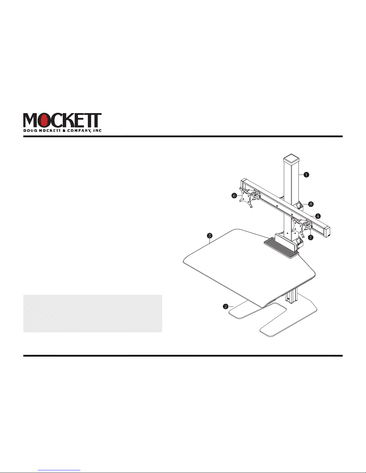
WS1-90 Installation Instructions
Supports 10-25 lbs. Can support monitors up to 28" each
(as long as the combined monitor weight does not exceed
maximum weight capacity.)
PAGE 1 OF 11
Step 2 | MOUNTS ................................................
Step 3
| WORK SURFACE
..................................
Step 4 | CENTER BEAM ......................................
Step 5
| EXTENSION BEAMS
(optional) ................
Step 6 | MONITOR TILTER .................................
Step 7 | MONITOR CUPS ...................................
Step 8 | CABLE MANAGEMENT ........................
Page 3
Page 4
Page 5
Page 6
Page 7
Page 8
Page 9
Page 10
Installation may require two people.
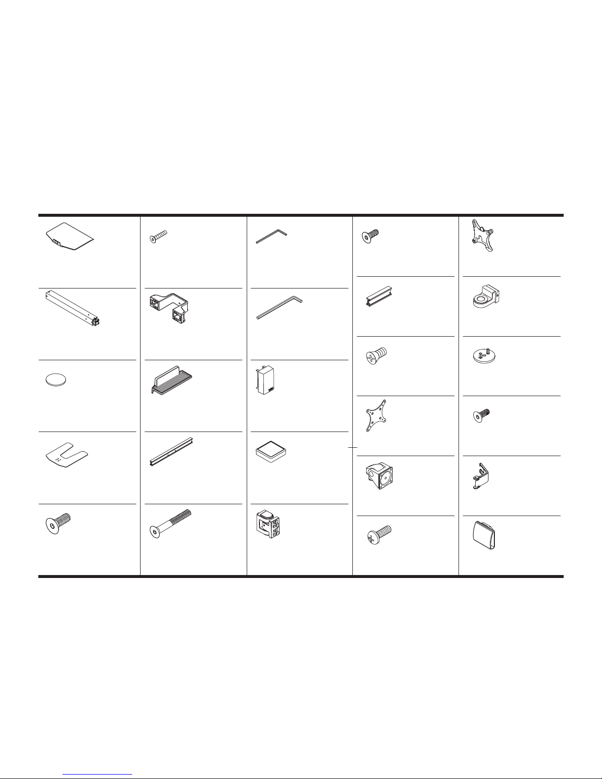
WS1-90 Parts List*
A Work Surface
411469
S
Utility Tray
111445
BB
Extension Beam (10" or 20")
111098-10 or 111098-20
KK
Monitor Cup
411351
B Column
411470-M
T
Center Beam (30")
111098-30
CC 10-32 x 3/8" PhPHS
702281
LL Dog Washer
111230-603
C Felt Pad
111464
U FHSCS 10-32 x 1-1/2"
711101
DD 75/100 mm VESA Adapter
105587
MM 10-32 x 1/2" FHSCS
711240
D Freestanding Base (Single & Dual)
111731
V 1/8" Allen Wrench
701312
EE Standard Monitor Tilter
405397
NN Column Cable Clip
111203-708
G
3/8-16 x 1" FHSCS
701124
W 7/32" Allen Wrench
701127
GG M4 x 12mm PhPHS
702096
OO
Extension Beam Cable Clip
111252
X
End Cap
111159-708
HH
QR VESA Adapter
109464
Y
Column Cap
111275-708
Q 10-32 x 1" FHSCS
711467
Z Hinge
411491
R Column Clamp
111040
AA 10-32 x 9/16" FHSCS
711100
PAGE 2 OF 11
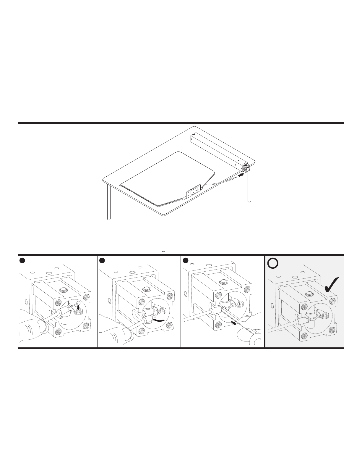
COLUMNStep 1
i
1 2 3
A
B
Use 7/32" Hex key to
press cable firmly into place.
Confirm cable is
properly seated
into position.
W
IMPORTANT: Do not pull excessively
on cable – doing so may result in
accidental actuation of column.
PAGE 3 OF 11
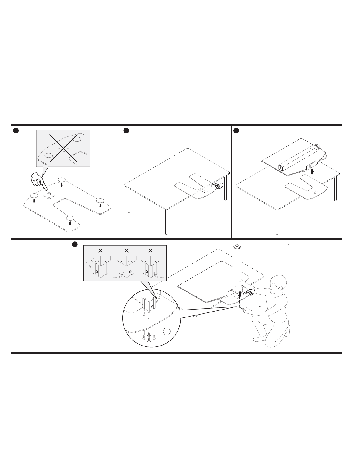
FREESTANDING BASE | MOUNTS
1 2 3
4
D or E
C
G
Step 2
Hang base plate over edge of
work surface to allow access
to countersunk holes. Side
of base plate with felt pads
should be face down.
Place work surface
on base plate to aid as a
counterbalance.
Note the orientation of
column cable exit and
base plate – cable should
exit in direction as shown.
7/32 "
PAGE 4 OF 11

WORK SURFACE
1 2
1/8"
Q
R
S
A
1
3
2
4
IMPORTANT: Tighten bolts evenly.
Work surface clamp should sit flush
against the column, ensure there
are no gaps. Also, it is important the
work surface clamp is level.
i
Step 3
Two people may be required to
install work surface to column.
One to hold the work surface
and the second person to secure
the column clamp.
Slide utility tray onto work surface.
Utility tray simply rests on top of
work surface.
PAGE 5 OF 11

333
2
444
1/8"
1/8"
CENTER BEAM
R
U
T
1
4 5
2 3
V
W
X
Y
Step 4
IMPORTANT: Tighten bolts evenly.
The beam should sit flush against
the column, ensure there are no gaps.
Also, it is important the work surface
clamp is level.
i
PAGE 6 OF 11

i
EXTENSION BEAMS
1/8"
1
3
2
Z
BB
AA
V
W
X
1/8"
Z
1/8"
AA
Step 5 (optional)
PAGE 7 OF 11

MONITOR TILTER
STANDARD TILTER & SPRING TILTER
CC
DD
EE
GG
1 2
Step 6
PAGE 8 OF 11

i
MONITOR CUPS
1/8"
1 2
7/32 "
KK
KK
LL
MM
Step 7
PAGE 9 OF 11

CABLE MANAGEMENT
NN
OO
Step 8
PAGE 10 OF 11

HEIGHT ADJUSTMENT
i
Is your height adjust button not working?
If so, make the adjustments below.
Slide workstation so that
the work surface hangs over
desk edge to allow access to
underneath the work surface.
Loosen the two screws
as shown.
Slide bracket in the direction
shown and tighten screws.
Test height adjust button –
readjust by repeating the steps
above as necessary.
Press button and hold. Lift up/down. Release to lock in place.
1
2
3
4
PAG E 11 OF 11
 Loading...