

Mockett PCS100C-U Quick Start Manual
NOTE:
PLEASE USE APPLICABLE
DATA BEZEL. (SEE DATA
INSTALLATION FOR MORE
INFORMATION.)
RIGHT VIEW
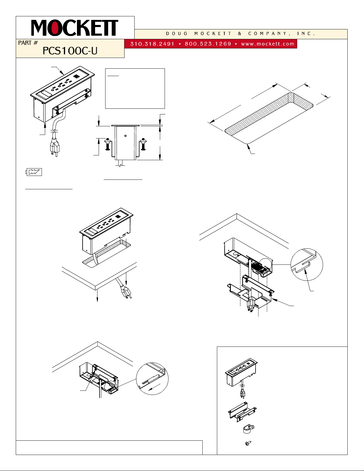
3-5/32"
3/4" MIN.
1-1/8" MAX.
TABLE
THICKNESS
3/32"
USB plugs for
CHARGING USE ONLY.
8-27/32" X
2-5/8"
8-1/2" X
2-1/8"
CUT OUT
1
2-1/8"
4 X
1/4" RAD.
Make a cut out in the desired work surface.
(NOTE: Cut out corners must contain 1/4" radius.)
8-1/2"
6 ft. CORD
2
Guide the power cord through the cut out. Install
the PCS100C into the cut out and make sure it
is fully leveled onto surface.
TABLE OF CONTENTS:
...................1 X PCS100C-U
(3 POWER,
1 DATA, &
1 DUAL USB)
...................1 X Clamp
...................2 X Wire Guides
...................2 X Screws
Loosen the clamp screws. Align the clamp from the
bottom mounting tabs.
3
Mounting
Tab
Clamp
Lock the clamp by sliding to the edge of the
mounting tab. Secure the unit by tightening the
(4) screws. Plug the unit into nearby outlet (outlet
should be close enough to where power cord is
not taut or strained) and unit is ready for use.
4
Screws
(SEE REVERSE SIDE FOR DATA JACK INSTALLATION INSTRUCTIONS)
PG 1of 2
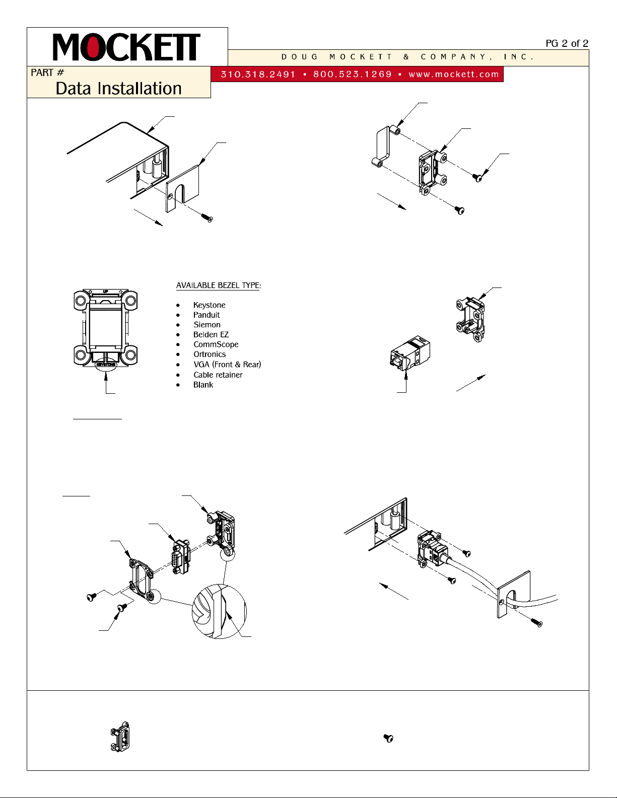
2
Use torq screwdriver to remove the blank
bezel in the unit.
Select the corresponding data type labeled on
the bottom rear of the data bezel.
3
1
Remove the cover using a philips screwdriver.
Cover
Installed Blank bezel
Torq
screws
REAR VIEW
Bezel Type
4
Wire the data insert and snap it to the bezel.
For VGA data, use the front and back VGA
bezel. Make sure the front and back bezel
align as shown above.
4
5
Install the data insert assembly upright in the
unit and use (2) torq screws. Guide the wire
from the cover opening. Secure the cover with
the screw.
Data
Insert
Bezel
Torq
Screws
Rear VGA
Bezel
Front VGA
Bezel
CONT.
TABLE OF CONTENTS:
Align
VGA
Insert
...................4 X Torq Scews
...................8 X Data Bezel
PCS98C
PCS99C
PCS100C
Mounting post
 Loading...