

Page 1
www.mobotix.com
The HiRes Video Company
T24 System Manual
HiRes Video Innovations
The German company MOBOTIX AG is known as the leading pioneer in network camera technology and its
decentralized concept has made high-resolution video systems cost ecient.
MOBOTIX AG • D-67722 Langmeil • Tel: +49-6302-9816-103 • Fax: +49-6302-9816-190 • [email protected]
EN
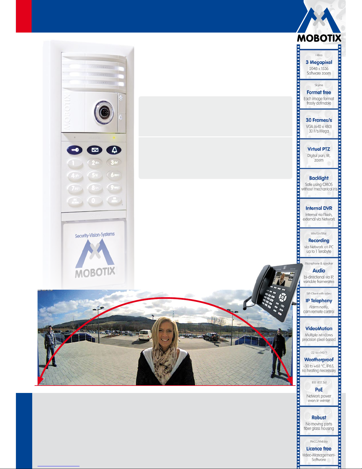
HD Super Panorama: From wall to wall without any blind spots
180°
Part 1:
System Overview And Installation
Installation and cabling
(for the installer)
Part 2: Start-Up And Configuration
Software and network
(for the system administrator)
60.167_EN_V3_07/2013
Page 2

2/148
© MOBOTIX AG • Security-Vision-Systems • Made in Germany
www.mobotix.com • [email protected]
T24 System Manual Part 1: Contents
T24-KeypadRFID (access module)
• Keyless access (RFID and PIN)
• Operate voice mailbox
• Contact remote stations
• Incl. RFID transponder cards
T24-Info/T24-Info2wire+ (info module)
• With integrated Mx2wire+ unit (optional)
• Data and power (PoE) via two-wire connection
• Instead of connection via network cable
• For two-wire cables up to 500 m
T24-DoorMaster (indoors)
• Opens door, doorbell on/o
• Status LEDs for door and messages
• Backup power supply with battery
• Connects to door opener and sensors
T24-CamCore (camera module)
• Allround view with no blind spots
• Internal memory
• Speaker
• Microphone
Page 3

3/148
© MOBOTIX AG • Security-Vision-Systems • Made in Germany
www.mobotix.com • [email protected]
This T24 System Manual Part 1 (system overview and installation) is complemented by T24
System Manual Part 2 (start-up and configuration). If you no longer have a manual at your
disposal, you can download a PDF file from the MOBOTIX website (www.mobotix.com >
Support > Manuals).
Foreword 8
Hemispheric IP Video Door Station 10
Allround View With No Blind Spots 12
Overview Of Modules 14
Individual Components: Outdoors 16
Individual Components: Indoors 18
Configuration Examples 20
System Image 22
1 System Overview 24
1.1 Outdoor Station 24
1.1.1 Hemispheric Camera T24-CamCore 24
1.1.2 Ethernet Terminal Board T24-OPT-ETH 26
1.1.3 Access Module T24-KeypadRFID 28
1.1.4 Info Module T24-Info 30
1.1.5 T24-Info2wire+ (Info Module With Indoor Unit) 32
1.1.6 Housing And Module Frames 36
1.2 T24-DoorMaster 42
1.3 Remote Stations 44
1.3.1 Grandstream IP Video Telephone GXV3140 44
1.3.2 MxEasy Video Management Software 46
1.4 Accessories 48
1.4.1 NPA-PoE Set 48
1.4.2 T24-OPT-IO (Extended Terminal Boards) 49
1.4.3 Additional Devices For PoE Power Supply 50
1.4.4 Additional Video Remote Stations 51
1.4.5 Door Sensors 51
1.4.6 Electrical Door Opener 51
SYSTEM MANUAL PART 1 - SYSTEM OVERVIEW AND INSTALLATION
Page 4

4/148
© MOBOTIX AG • Security-Vision-Systems • Made in Germany
www.mobotix.com • [email protected]
T24 System Manual Part 1: Contents
2 Installation 52
2.1 Overview: Connection And Wiring Diagrams 52
2.1.1 With A T24-DoorMaster 52
2.1.2 Without A T24-DoorMaster 54
2.1.3 With T24-Info2wire+ And T24-DoorMaster 56
2.1.4 Recommendation For Cabling 58
2.1.5 Installation Tip: Replacing An Existing Doorbell With The T24 60
2.2 Remote Stations And Network Connection 62
2.2.1 Notes On Cable Lengths And Power Supply 62
2.2.2 Direct Connection Of One Remote Station 62
2.2.3 Network Connection With Multiple Remote Stations 63
2.3 Mounting The Frame And Housing 66
2.3.1 Determining The Installation Position 66
2.3.2 Inserting All The Cables 68
2.3.3 Attaching The Housing 70
2.3.4 Cabling In The On-Wall Housing 72
2.3.5 Mounting The Terminal Board And Fitting The Network Cable 74
2.3.6 Sticking The Seal In Place 75
2.3.7 Attaching The Frame And Connecting The Anti-Theft Protection 76
2.3.8 Mechanical Anti-Theft Protection Lock 78
2.4 Installing The T24 Modules 80
2.4.1 Installing The Camera Module T24-CamCore 80
2.4.2 Installing The T24-KeypadRFID 84
2.4.3 Installing The Info Module T24-Info 88
2.4.4 Installing The Info Module T24-Info2wire+ 90
2.4.5 Labeling The Info Modules 92
2.4.6 Removing And Exchanging Modules 94
2.5 Installing The T24-DoorMaster 96
2.5.1 Overview Of Connectors 96
2.5.2 Connection Diagrams For Door Opener Versions 98
2.5.3 Mounting Instructions 100
2.5.4 Installation Using Cavity Or In-Wall Socket 103
2.6 Installing The Indoor Unit T24-Info2wire+ 106
2.6.1 Overview Of Mx2wire+ Technology And Connectors 106
2.6.2 Mounting Instructions 108
2.6.3 Installation Using Cavity Or In-Wall Socket 109
2.6.4 Installation With Surface-Mounted Socket 111
2.6.5 Function Of Mx2wire+ Status LEDs 113
Page 5
5/148
© MOBOTIX AG • Security-Vision-Systems • Made in Germany
www.mobotix.com • [email protected]
2.7 Connecting External Devices To The Door Station 114
2.7.1 Using The IO Module T24-OPT-IO 114
2.7.2 Using The Keypad Signal Outputs 118
2.8 Finishing The Installation 120
2.8.1 Checking The Wiring And Activating The Anti-Theft Protection 120
2.8.2 Configuring The T24-DoorMaster 122
2.9 Installation In The Siedle Vario System 124
2.9.1 Integrable Modules 124
2.9.2 Determining The Installation Position 128
2.9.3 Preparing Network And Power Connections 129
2.9.4 IO Module And Terminal Connectors 130
2.9.5 Connections In The Door Station 132
2.9.6 Connecting, Securing And Removing Modules 138
Notes
Download the latest version of this manual as a PDF file from www.mobotix.com
(Support > Manuals). All rights reserved. MOBOTIX
®
and MxEasy™ are registered
trademarks of MOBOTIX AG. Microsoft, Windows und Windows Server are registered
trademarks of the Microsoft Corporation. Apple, the Apple logo, Macintosh, OS X and
Bonjour are trademarks of Apple Inc. Linux is a trademark of Linus Torvalds. All other
marks and names mentioned herein may be trademarks or registered trademarks
of the respective owners. Copyright © 1999-2011 MOBOTIX AG, Langmeil, Germany.
Information subject to change without notice!
!"#$ &'("#)*+&"',
---.)"/"+&0.1")
Page 6
6/148
© MOBOTIX AG • Security-Vision-Systems • Made in Germany
www.mobotix.com • [email protected]
Important Notes
Electrical Installation
Electrical systems and equipment may only be set up, changed and maintained
by a qualified electrician or under the management and supervision of a qualified
electrician in accordance with electrotechnical regulations.
Legal Aspects Of Video And Audio Recording
When using MOBOTIX products, privacy and data protection regulations regarding
video and audio recording must be observed. Depending on the country and installation site of the IP Video Door Station, the recording of video and audio data
may be subject to special constraints or may be prohibited. All users of MOBOTIX
products are therefore requested to inform themselves of and comply with all currently
applicable regulations. MOBOTIX AG will not assume any responsibility for product
use that does not comply with the local laws.
Network Security
MOBOTIX products combine all necessary configuration options for operating in
Ethernet networks in a manner that complies with data protection regulations. The
operator is responsible for the data protection concept across the entire system. The
necessary basic settings to prevent misuse can be configured in the software and
are password protected. This prevents unauthorized access by unknown parties.
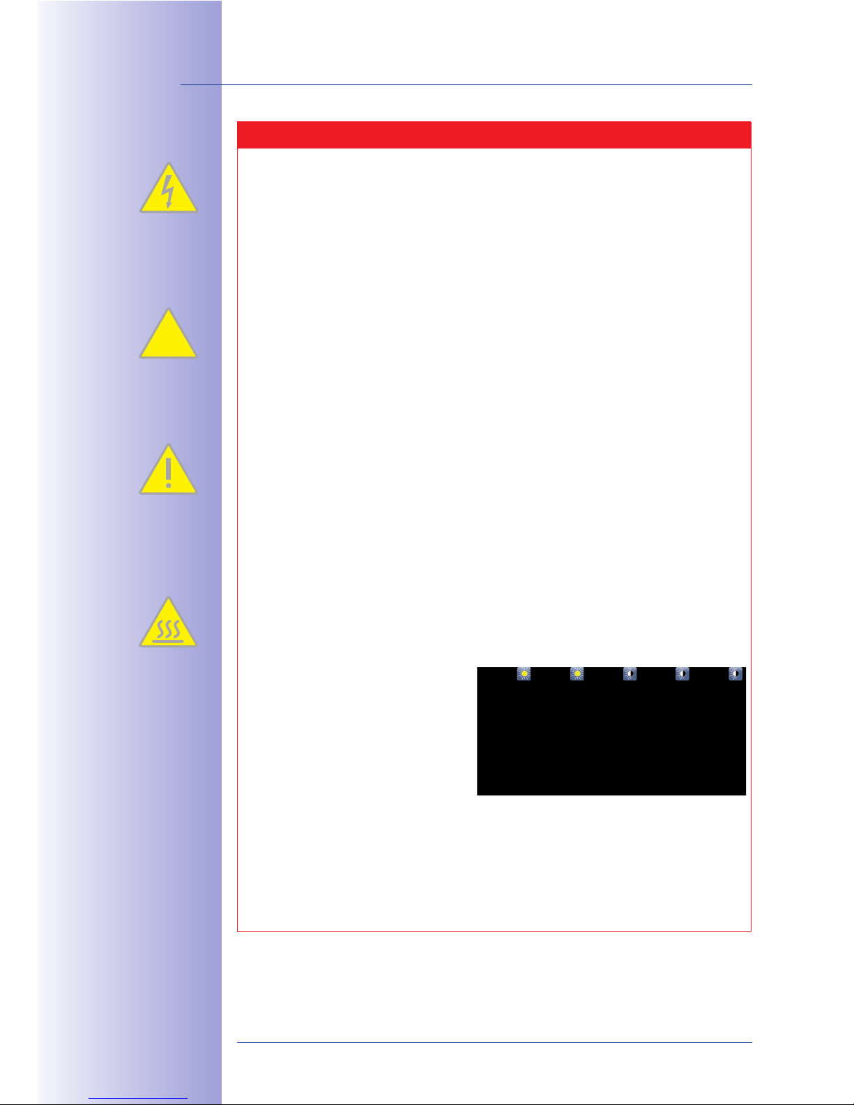
Risk Of Overheating When Exposed To Direct Sunlight
When mounting black, dark gray or amber-colored T24 IP Video Door Stations in
locations where the device is exposed to direct sunlight, the housing temperature
can exceed the maximum allowed temperature limit.
This can result in electronic failures and
injuries especially when touching exterior
metal parts. If the intended use of the
device is at an (unprotected) outdoor
location, you should only install white
or silver-colored modules and frames.
Do Not Remove Lens Cover
The camera module of the door station may not be operated without the installed
transparent lens cover. The camera is no longer weather-proof when operated
without the lens cover; the removal of the cover exposes the metal ring around the
lens, which is especially prone to overheat in high temperatures. Therefore, anyone
who touches the ring with their bare hand is at risk of being burned.
§
T24 System Manual Part 1: Inhalt
Page 7

Page 8
8/148
© MOB Made in Germany
T24 System Manual Part 1: Foreword
FOREWORD
Dear MOBOTIX customer,
Congratulations on your decision to purchase an exceptionally versatile and innovative
IP Video Door Station “made in Germany.” The T24 system contains a hemispheric door
camera with a 3.1 megapixel color sensor (T24-CamCore) and captures the entire room
180° from wall to wall and from floor to ceiling without any blind spots.
Chapter 1 of the System Manual Part 1 contains all product details and
the technical information of the system. Chapter 2 deals with the
installation of the T24 with a direct network connection or the optional
connection via two (existing) wires. Part 2 of the System Manual
will demonstrate how you operate the door station and configure
it to meet your specific needs. The two System Manuals are supplemented
by an Operating Manual for the T24 IP Video Door Station.
If you would like to use a computer for the installation or as a remote
station, make sure to use the free MOBOTIX operating software MxEasy.
You can download MxEasy and its manual free of charge under
“Support” on the MOBOTIX website.
If you have any questions, our support and international sales sta are available at
[email protected] and [email protected] Monday to Friday, 8 a.m. to 6 p.m.
(German time). Calling support is free of charge (not including your connection costs).
We would like to thank you for your trust and wish you all the best with your new highperformance MOBOTIX T24 IP Video Door Station.
Page 9
9/148
© MOBOTIX AG • Security-Vision-Systems • Made in Germany
www.mobotix.com • [email protected]
!"#$ 2$13#&+4 +5*'62
+" * )*0&)3) "7$#7 $-
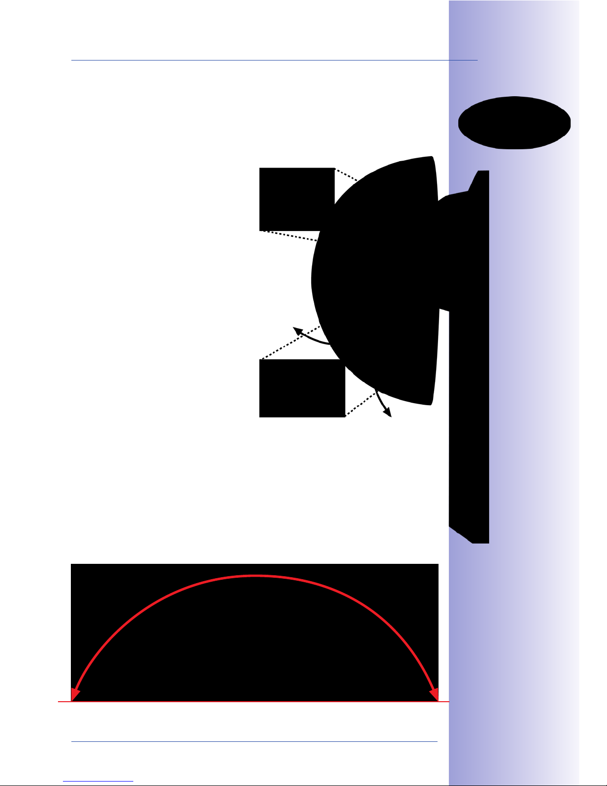
HD 360° Full Image: Entire scene in one view
HD Super 180° Panorama
Page 10
10/148
T24 System Manual Part 1: Hemispheric IP Video Door Station
TIX AG • Security-Vision-Systems • Made in Germany
www.mobotix.com • [email protected]
What Are The Specific Advantages Of A MOBOTIX IP Video Door Station?
The new T24 IP Video Door Station from MOBOTIX oers an innovative, powerful solution
that is easy to install and takes a dierent approach to the solutions available on the
market up to now. The T24 is based on the international video telephony standard VoIP/
SIP with H.264 and G.711. All of the modules oered for outdoor use are weatherproof,
maintenance-free and can be used in temperatures ranging from -30°C to +50°C (-22°F
to 122°F). Here are the most important system advantages at a glance:
Allround View With No Blind Spots
With 3.1 megapixels and an internal memory, this hemispheric door camera records the
entire entrance area. No blind spots from wall to wall and from floor to ceiling.
Two-Way Video Communication Worldwide
When the doorbell rings, a connection is established with an IP video phone or a standard
computer via the network. For two-way video communication and for opening the door.
Recording With Sound
The camera in the door station can record events automatically. For example, when
someone rings the doorbell or if something moves in front of the door.
Keyless Access
Who has access and who doesn’t? The door opener can be controlled tamper-proof
using the T24-KeypadRFID with a PIN code or an RFID transponder.
Integrated Message Function
Digital voice messages for residents can be left directly at the door station and played
back after authentication.
Very Simple Installation
The door station is connected to the network via an Ethernet cable or via two-wire cabling
thanks to Mx2wire+ technology.
85$ 89: )";3<$2 *#$
*7*&<*/<$ ';&7&;3*<<4
"# &' * 2$+
MOBOTIX integrates hemispheric technology into existing
Siedle Vario Systems for added security thanks to superior
overview images and event-controlled recording of video
and sound.
Page 11
11/148
© MOBOTIX AG • Security-Vision-Systems • Made in Germany
www.mobotix.com • [email protected]
What Advantages Does MOBOTIX Oer Over Other Video Door Stations?
Thanks to its HiRes image quality, decentralized technology and a wide range of features,
MOBOTIX oers not only an outstanding door camera but also a professional security
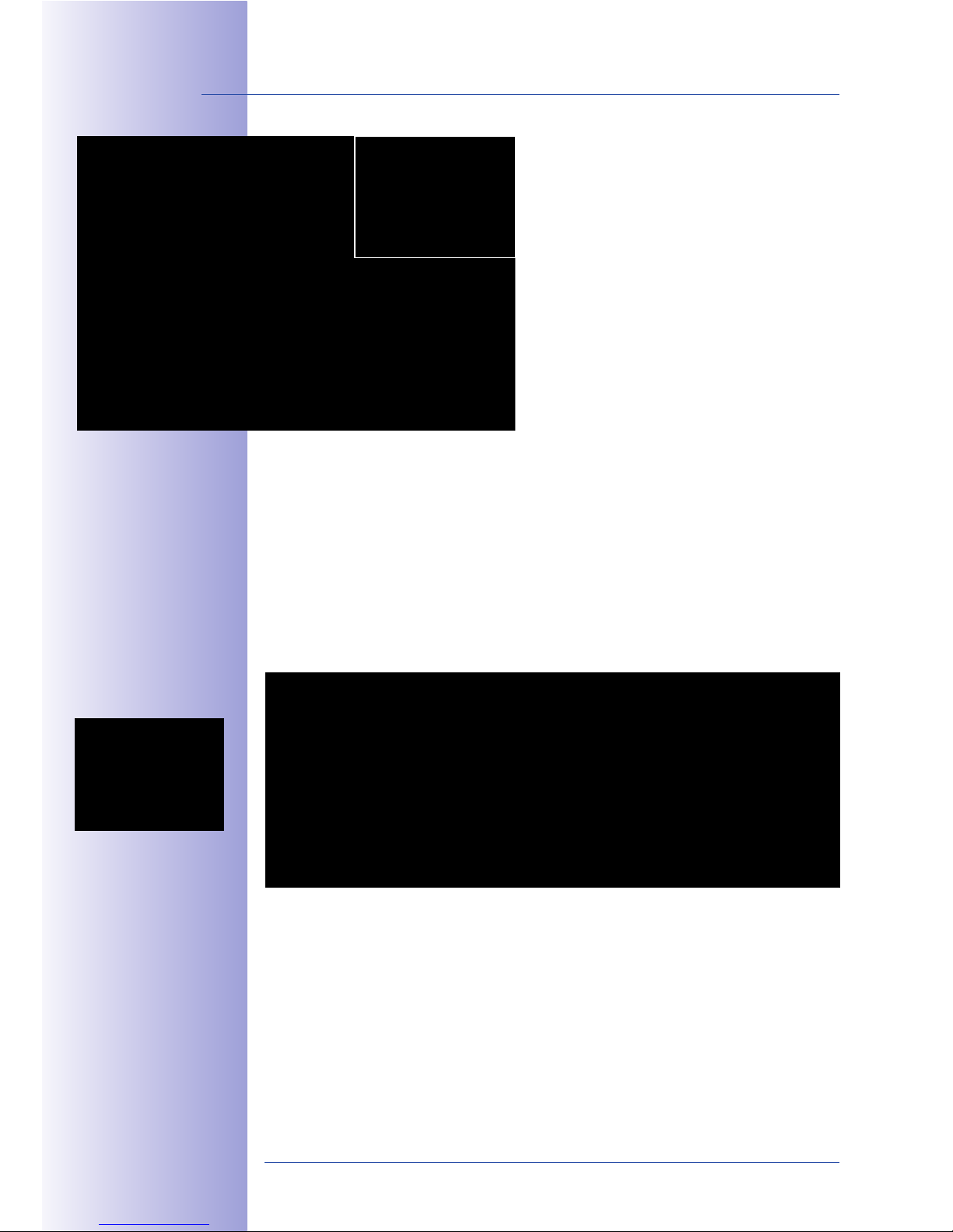
camera in a single device. MOBOTIX Hemispheric Video Technology was successfully
introduced to the network video market
in 2008. This technology is an important
component of the MOBOTIX video door
stations, which provide perfect, highresolution overview images thanks to
a fisheye lens with a 180° image angle.
This allows the camera to cover the
entire entrance area from wall to wall
and from floor to ceiling without any
blind spots, and without ever needing
to mechanically pan or tilt.
But the camera, with its unrivaled image
quality and panoramic view, is much
more than just a modern “door spy.”
The camera has an integrated highspeed processor that provides a range
of functions similar to those available
in MOBOTIX security cameras used
in banks and airports. Thanks to the
integrated Video Motion Detection,
when the camera registers movement in
the image or detects suspicious noises,
it automatically starts recording smooth video with sound while simultaneously
sending an e-mail or SMS to the residents of the building or to a security company.
In addition, a message may be left for the residents at the door station; it works
just like a telephone answering machine with the addition of video and audio
recording by the camera module. Additionally, an audio message for visitors
can be played back automatically when the doorbell button is pushed.
=&25$4$ 7&$-
85$ 1*)$#* 1*>+3#$2 +5$
$'+&#$ 5$)&2>5$#&1*< *#$*
&' (#"'+ "( +5$ 1*)$#*
<$'2 *'; ;&2><*42 &+ '
* 32$#?(# $';<4 ("#)*+
*2 * 1"##$1+$; )*@$ "#
&)*@$ 2$1+&"'A "# *2 *'
BC D3>$# EFGH >*'"#*)*
HD Super 180° Panorama
Page 12
12/148
© MOBOTIX AG • Security-Vision-Systems • Made in Germany
www.mobotix.com • [email protected]
T24 System Manual Part 1: Allround View With No Blind Spots
Hemispheric HiRes Camera
Thanks to the fisheye lens with its 180° image
angle, the camera records the entire entrance
area without having to be mechanically panned
or tilted – without any blind spots, from wall to
wall, floor to ceiling. It’s impossible to “slip by”
this camera. On the monitor located at the remote
station, the operator can change the current image
section in seconds: from a close-up of the visitor
all the way to an overview panorama.
The hemispheric T24 door camera T24-CoreCam
has a virtual, purely digital PTZ feature (pan/tilt/
zoom). The image captured by the hemispheric
camera can be zoomed smoothly, and you can
simultaneously move to any section of the image in seconds, for example, using the
mouse or the four large arrow keys on the Grandstream video telephone (left, right, up,
down). This is similar to a mechanical PTZ camera, but without the maintenance and wear.
A Superior Overview Increases Security
The fisheye lens of the camera records the entire hemisphere of the scene without any
blind spots and displays this image as the first part of the 360° full image. Here, there are
technical limitations - predominantly at the edges of the image, where the geometric shape
of the objects is heavily distorted, making them dicult to for the human eye to evaluate.
For this reason, the camera uses its integrated software to correct the images in the live
view so that it can deliver user-friendly images at the remote video station. The operator
can now digitally tilt, pan and zoom the image from the comfort of the remote station.
89: IJGH =3<< K)*@$
D$$ '@ +5$ $'+&#$
21$'$ -&+5 +5$ 89:
Standard 90°
Original MOBOTIX T24 Image: 1280 x 480
HD Super 180° Panorama
Page 13
13/148
© MOBOTIX AG • Security-Vision-Systems • Made in Germany
www.mobotix.com • [email protected]
180° Field Of View With No Blind Spots
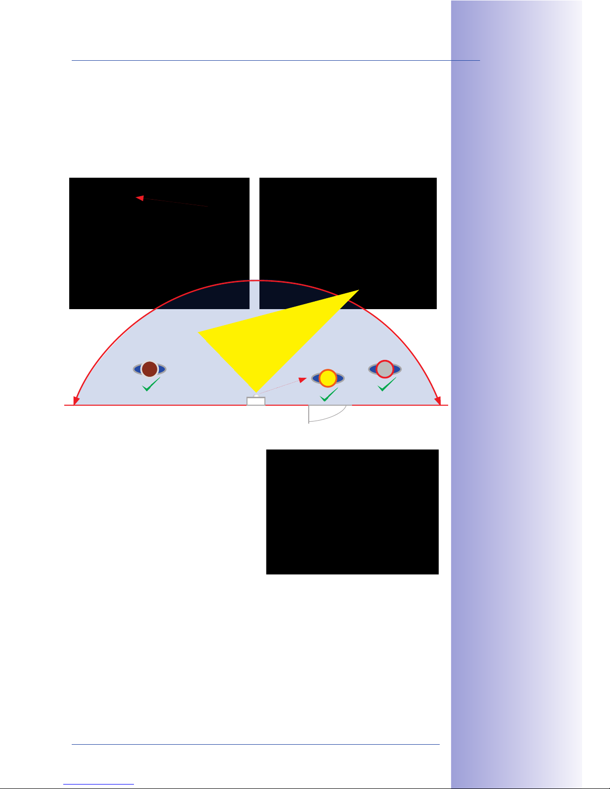
Conventional door cameras have a standard 90° lens, meaning that they are only able
to capture visitors standing directly in front of the lens. However, much of the time, the
door station is not mounted in the immediate vicinity of the door, so the camera is at an
angle to the visitor (see image). Even in this case, thanks to its 180° image angle, the
T24 delivers perfect images.
Direct Views Up And Down
And the hemispheric camera can do much,
much more: it can record the area on the
floor in front of the door, for example, even
the often overlooked area underneath the
door station. And the T24 does all of this
using only its software – without the need
for moving parts or motors. This camera is
silent, discreet and unobtrusive.
Also, this quick look down is incredibly practical when checking, for example, whether the
daily paper is already in front of the door. Of course, it is also possible to look upwards
under the ceiling as well.
L&@5+, M#&@ '*<
!MNM8KO 89: &)*@$
Door intercom system
(located next to the door)
Standard 90°
Door
HD Super 180° Panorama
Original MOBOTIX T24 image
M#&@&'*< !MNM8KO
89: )*@$ P$'<*#@$;
)*@$ 2$1+&"'Q
Page 14
14/148
© MOBOTIX AG • Security-Vision-Systems • Made in Germany
www.mobotix.com • [email protected]
T24-System Manual Part 1: Overview Of Modules
Product Overview: T24 Modules
In addition to the hemispheric HiRes camera, the latest MOBOTIX development also includes
a multifunctional keypad module with transponder technology for keyless access and
control of message functions (T24-KeypadRFID).
A particular advantage of the T24 is the minimal amount of cabling involved – either a
standard Ethernet cable (for example, CAT7) or existing bell wire is sucient to connect
the door station to the network in the building and to supply it with power. Only a PoE
switch is necessary to connect remote stations (VoIP video phone or computer) and supply
power. The PoE switch can be located in an electrical cabinet, for example.
Hemispheric camera
Allround view with no
blind spots, with internal
memory, speaker and
microphone
Keypad
Keyless entry (RFID & PIN),
voice mailbox operation
Info module
Optionally with integrated
Mx2wire+ unit to connect
the T24 via bell wire
(data and power)
Page 15
15/148
© MOBOTIX AG • Security-Vision-Systems • Made in Germany
www.mobotix.com • [email protected]
Hemispheric Door Camera With Allround View And No Blind Spots (T24-CamCore)
With 3.1 megapixels and an internal memory, this hemispheric door camera records the
entire entrance area. No blind spots from wall to wall and from floor to ceiling. The camera
can record events automatically. For example, when someone rings the doorbell or if
something moves in front of the door. The camera module with a
remote station can be used as a compact basic video door station
thanks to the integrated doorbell and light buttons. The camera
saves high-resolution video with lip-synchronous sound directly to
the integrated MicroSD flash card (up to 64 GB) without requiring an
external storage device or computer and with no additional network
load. The storage space is for up to 800,000 panorama images or
66 hours of video recordings.
Keypad With Contactless RFID Technology (T24-KeypadRFID)
This MOBOTIX-developed module can be used for several functions.
Outdoors, it functions as the access control interface, either by
entering a code on the keypad or by means of keyless access using
a transponder (as a check card).
The module can also be used by visitors and residents to record
and play back messages.
Info Module With/Without Mx2wire+ Technology (T24-Info/T24-Info2wire+)
The info module features a backlit house number field and may
also include an optional Mx2wire+ unit. This unit is needed if the
outdoor station is to be connected to the PoE switch with an existing
bell wire via a second Mx2wire+ indoor unit instead of directly using
an Ethernet cable.
T24-DoorMaster With Backup Power Supply (Battery)
The door station may be coupled with a T24-DoorMaster with access
code memory, making it impossible to open the door by forcibly
removing the system and bypassing the connecting cable. A built-in
rechargeable battery powers both the electrical door opener and
the keypad in the outdoor station and guarantees that the door can
be accessed using a transponder or PIN even in the case of power
failure. For indoor installations, the T24-DoorMaster also functions
as a doorbell. The device features two status LEDs and two function
buttons (doorbell, door opener).
Page 16
16/148
T24 System Manual Part 1: Individual Components: Outdoors
© MOBOTIX AG • Security-Vision-Systems • Made in Germany
www.mobotix.com • [email protected]
T24 Components: Outdoors
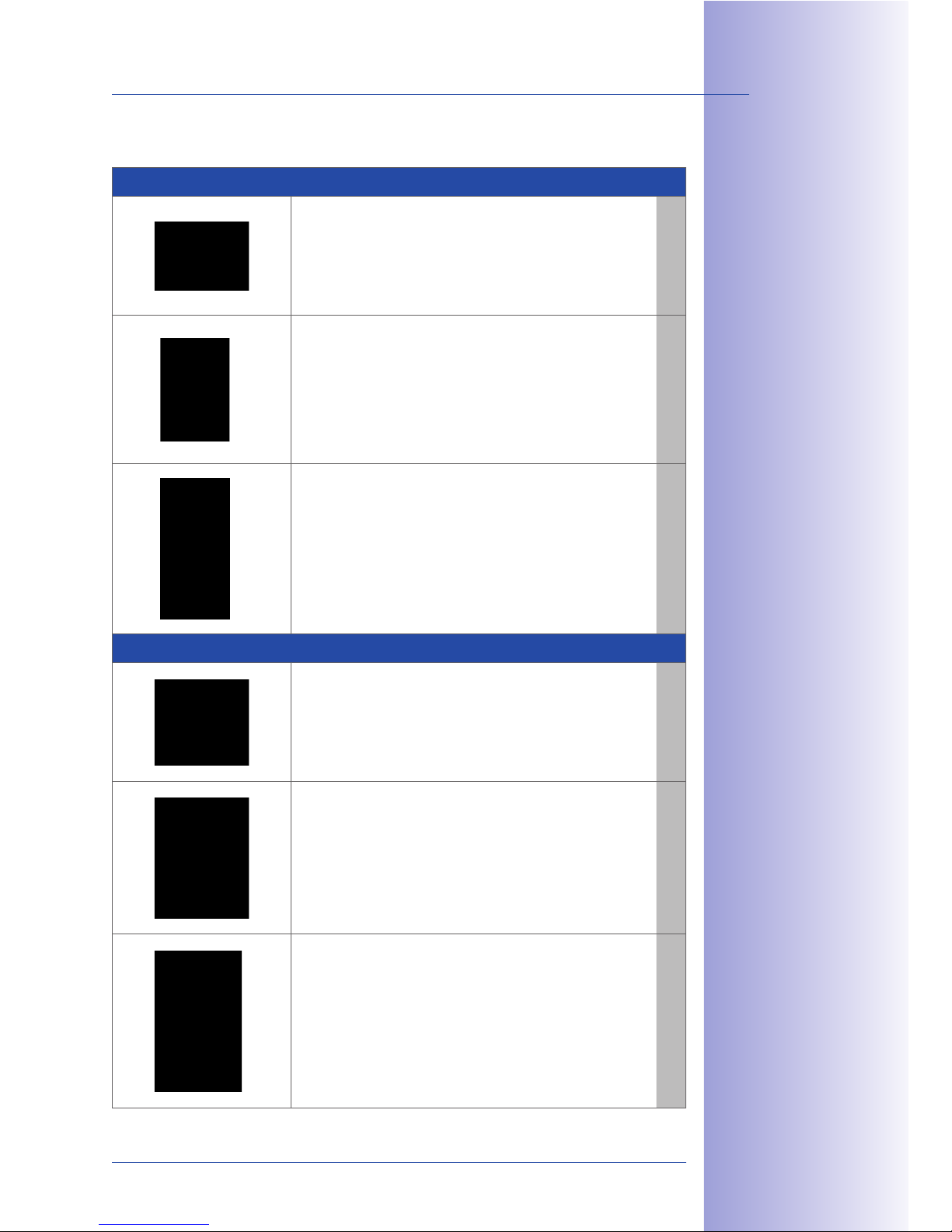
Terminal boards
T24-OPT-ETH: Securely connects the camera module with the
mounted 8 wires of the network patch cable via RJ45 connector.
Only for T24 versions without Mx2wire+.
MX-OPT-IO2
T24-OPT-IO: The board provides an additional 8 signal inputs and
3 signal outputs to connect external devices (doorbell, light, etc.).
MX-OPT-IO1
Modules
T24-CamCore: Fisheye lens (for 360° panorama view) and inte-
grated live image correction, high-resolution 3.1 megapixel color
sensor, speaker, microphone and 4 GB data storage for approx.
250 one-minute video clips or 60,000 VGA images.
MX-T24M-Sec-D11
T24-KeypadRFID: Keyless and scheduled access. This requires
the user to enter a code, or it can open the door in response
to an RFID transponder card. The voice mailbox can also be
operated via the keypad.
MX-Keypad1-EXT
T24-Info: Provides the option to display the house number
and/or name to the door station. The module is equipped with
permanent backlighting using energy-saving and long-lasting
LED technology.
MX-Info1-EXT
T24-Info2wire+: The info module with Mx2wire+ technology
and a second Mx2wire+ unit for mounting inside the building
oers users not only the standard info module functions but also
the option to connect and supply power to the door station via
existing two-wire cabling instead of a network cable.
MX-2wire-Info1-EXT
Frame
Single frame: 131 x 143 x 18 mm (W x H x D).
Integrated electromagnetic anti-theft protection.
Includes special key for module unlocking, housing seal
and installation material.
MX-OPT-Frame-1-EXT
Double frame: 131 x 233 x 18 mm (W x H x D).
Integrated electromagnetic anti-theft protection.
Includes special key for module unlocking, housing seal
and installation material.
MX-OPT-Frame-2-EXT
Triple frame: 131 x 333 x 18 mm (W x H x D).
Integrated electromagnetic anti-theft protection.
Includes special key for module unlocking, housing seal
and installation material.
MX-OPT-Frame-3-EXT
85$ 1*)$#* )";3<$ &2 *<2"
*7*&<*/<$ -&+5 * >*#+&13<*#<4
<&@5+?2$'2&+&7$ NRS 2$'2"#
P!O?89:!?D$1T&@5+?TEEQ
85$ ';""# 3'&+ &2
*<-*42 >*#+ "( +5$
89:?K'("9-&#$U
&'(" )";3<$
M'$ *;)&' *'; 2$7$#*<
32$# L=KC 1*#;2 *#$
&'1<3;$; -&+5 +5$ 6$4>*;
Page 17
17/148
© MOBOTIX AG • Security-Vision-Systems • Made in Germany
www.mobotix.com • [email protected]
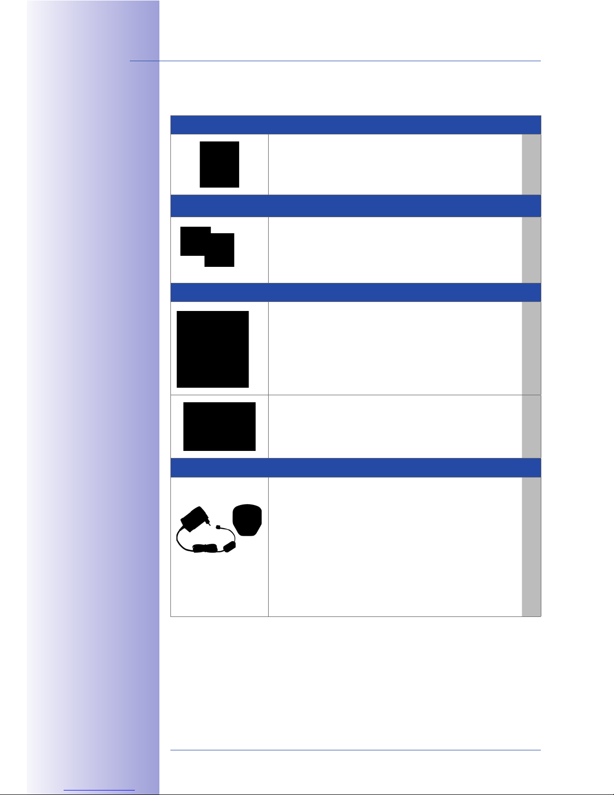
On-wall housing
Single on-wall housing: 126 x 138 x 31 mm (W x H x D).
Metal-reinforced housing.
MX-OPT-Box-1-EXT-ON
Double on-wall housing: 126 x 227 x 31 mm (W x H x D).
Metal-reinforced housing.
MX-OPT-Box-2-EXT-ON
Triple on-wall housing: 126 x 327 x 31 mm (W x H x D).
Metal-reinforced housing.
MX-OPT-Box-3-EXT-ON
In-wall housing (incl. plasterwork protection)
Single in-wall housing:
123 x 138 x 52 mm (W x H x D).
The in-wall housing is securely connected with the
subsurface or brick work. It can also be used to ensure easy
installation in cavities.
MX-OPT-Box-1-EXT-IN
Double in-wall housing:
123 x 228 x 52 mm (W x H x D).
The in-wall housing is securely connected with the subsurface
or brick work. It can also be used to ensure easy installation
in cavities.
MX-OPT-Box-2-EXT-IN
Triple in-wall housing:
123 x 328 x 52 mm (W x H x D).
The in-wall housing is securely connected with the subsurface
or brick work. It can also be used to ensure easy installation
in cavities.
MX-OPT-Box-3-EXT-IN
85$ #$V3 #$; W325?
)"3'+&'@ ">$'&'@ 5*2
+5$ ("<<"- '@ ;&)$'2&"'2
P-&;+5 0 5$&@5+Q,
D '@<$ 5"32&'@,
EEX 0 E9Y ))
C"3/<$ 5"32&'@,
EEX 0 9EF ))
8#&><$ 5"32 '@,
EEX 0 IEF ))
Page 18
18/148
T24 System Manual Part 1: Individual Components: Indoors
© MOBOTIX AG • Security-Vision-Systems • Made in Germany
www.mobotix.com • [email protected]
T24 Components: Indoors
T24-DoorMaster With Backup Power Supply
The T24 may be coupled with the MOBOTIX T24-DoorMaster
with internal access code memory and battery for back-up
power supply, making it impossible to open the door by forcibly
removing the system and bypassing the connecting cable.
MX-Door1-INT
T24-Info2wire+ Indoor Unit
An Mx2wire+ set always consists of two devices that
communicate with one another. For this reason, the T24Info2wire+ info module in the door station also requires a
corresponding unit to connect to the network and to supply
power.
MX-2wire-Info1-EXT
Remote Stations
IP video telephone: MOBOTIX recommends the GXV3140 from
Grandstream as a remote video station for the T24 door station.
This modern IP video telephone is based on the world standard in
telephony - VoIP/SIP with H.264 - and provides a large color LCD
display with excellent image quality.
Grandstream GXV3140
MxEasy video management software: MOBOTIX provides the
MxEasy software (for Windows, Mac and Linux) free of charge
to configure and operate the T24 IP Video Door Station with a
network-enabled desktop or notebook computer.
Free of charge
Accessories
LAN/Power
PC Power
NPA-PoE-Set: The MOBOTIX Network Power Adapter Set (NPAPoE set) is a high-quality, robust, ultra-compact, and - above
all - multifunctional PoE injector with three connectors (network,
camera/PoE device, PC) and a universal power supply unit with
adapter plugs. The Network Power Adapter Set remotely supplies
the T24 door station and all other PoE devices with power in
accordance with the IEEE 802.3af standard. It is therefore possible
to secure the power supply for distances up to 100 m (300 ft)
using the network cable. As a result, the T24 IP Video Door Station
can be supplied with PoE power via the adapter and connected
directly to a Grandstream video telephone or to a computer
(integrated crossover function).
MX-NPA-PoE set
85$ ';""# 3'&+ &2
*<-*42 >*#+ "( +5$
89:?K'("9-&#$U
&'(" )";3<$
=#$$ ;"-'<"*; *+
---.)"/"+&0.1")
Page 19

19/148
© MOBOTIX AG • Security-Vision-Systems • Made in Germany
www.mobotix.com • [email protected]
T24: The Custom-Made IP Video Door Station
The T24 product line is a modular system that can be adapted to any customer needs. This
highly robust and weatherproof outdoor station (IP65, suitable for -30°C to +50°C / -22°F to
+122°F) is available in four attractive colors: white, silver, dark gray, black and amber.
You will find the T24 online configurator tool on the MOBOTIX website, which you can use
to plan your individual T24 door station.
You can choose the individual components step-by-step so that no individual component
is forgotten. Accessories required for your selected components are automatically added
by the configuration tool.
After you have finished the configuration, the system creates a preview image of the
system as well as a parts list, which you can hand to your electronics specialist for an
installation quote.
The web configurator can be found on the MOBOTIX website under
the main menu item Products > T24 configurator.
T24: A Future-Oriented System
With the T24, MOBOTIX oers a new product range for the home
automation market and it will be extended and complemented with
other new products.
For example, a suitable bell module with up to four keys and integrated
RFID technology will soon be available. And the best part for all MOBOTIX
customers: all future T24 innovations are also compatible with T24
systems that have already been purchased.
---.)"/"+&0.1") Z
[#";31+2 Z 89:
\"']@3#*+"#
M'<4 -5&+$ *';
2&<7$#?1"<"#$; K[
^&;$" C""# D+*+&"'2
25"3<; /$ $0>"2$;
+" ; #$1+ 23'<&@5+
P#&26 "( "7$#5$*+&'@
"' ;*#6 23#(*1$2Q
85$ 1"<"# *//#$7&*+&"'
&2 *;;$; *+ +5$ $'; "(
+5$ "#;$# '3)/$# &'
$*15 1*2$ P("# $0*)><$A
-5&+$ 89:?\*)\"#$,
!O?89:!?D$1?CEE?[SQ
white (PW) silver (SV) dark gray (DG) black (BL) amber (AM)
Page 20
20/148
T24 System Manual Part 1: Configuration Examples
© MOBOTIX AG • Security-Vision-Systems • Made in Germany
www.mobotix.com • [email protected]
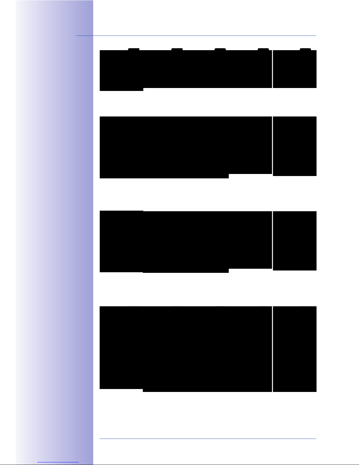
^*#&"32 1"']@3#*+&"'
$0*)><$2 &' *<< *7*&<*/<$
!MNM8KO 1"<"#2
M'<4 -5&+$ *';
2&<7$#?1"<"#$; K[
^&;$" C""# D+*+&"'2
25"3<; /$ $0>"2$;
+" ;&#$1+ 23'<&@5+
P#&26 "( "7$#5$*+ '@
"' ;*#6 23#(*1$2Q
Camera and
info module
in double frame
(PW)
Camera, keypad
and info module
in triple frame
(PW)
Camera, keypad
and info module
in triple frame
(SV)
Camera, keypad
and info module
in triple frame
(DG)
Camera, keypad
and info module
in triple frame
(BL)
Camera, keypad
and info module
in triple frame
(AM)
Camera and
info module
in double frame
(SV)
Camera and
info module
in double frame
(DG)
Camera and
info module
in double frame
(BL)
Camera and
info module
in double frame
(AM)
Camera and
keypad
in double frame
(PW)
Camera and
keypad
in double frame
(SV)
Camera and
keypad
in double frame
(DG)
Camera and
keypad
in double frame
(BL)
Camera and
keypad
in double frame
(AM)
Camera
in single frame
(PW)
Camera
in single frame
(SV)
Camera
in single frame
(DG)
Camera
in single frame
(BL)
Camera
in single frame
(AM)
Page 21

Page 22
22/148
© MOBOTIX AG • Security-Vision-Systems • Made in Germany
www.mobotix.com • [email protected]
T24 System Manual Part 1: System Image
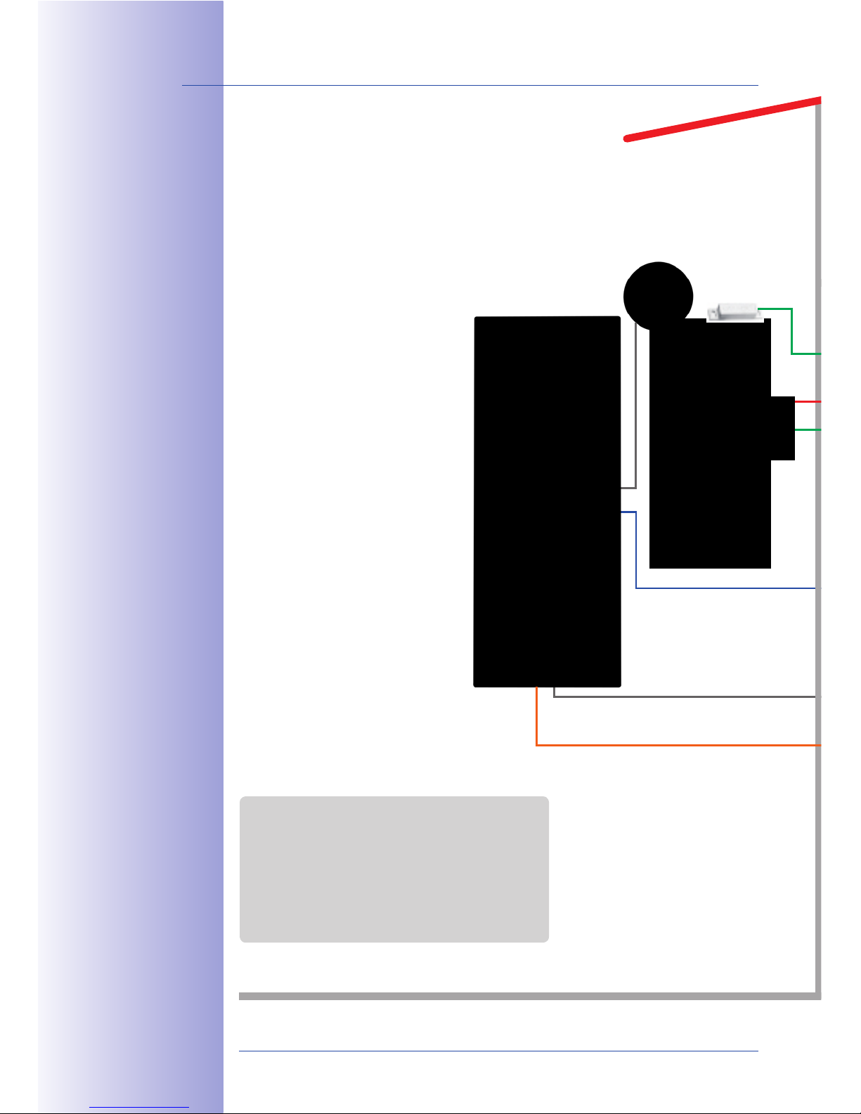
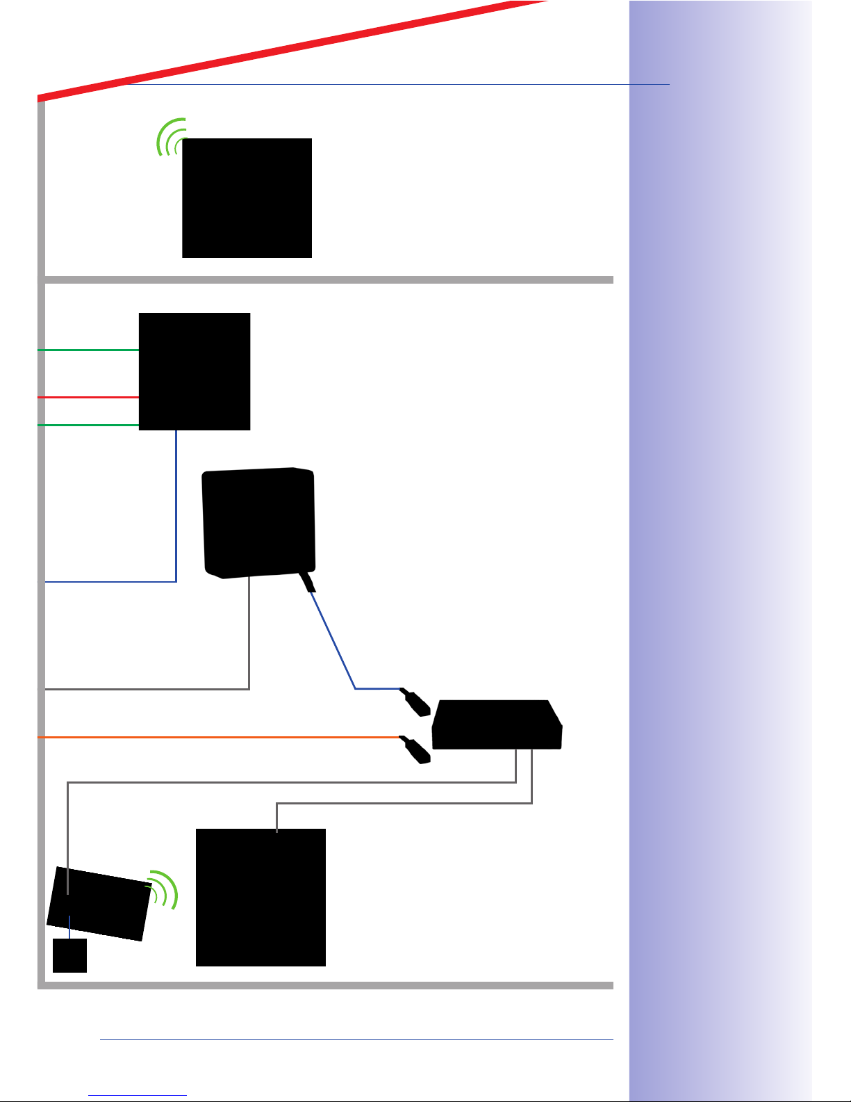
SYSTEM OVERVIEW: T24 IP VIDEO DOOR STATION
What does a typical system look like and what components are included? This section
describes the setup for a complete system with a video door station including a T24DoorMaster, T24-KeypadRFID and T24-Info2wire+ info module with Mx2wire+ technology
to connect the door station using existing two-wire cabling. In newer buildings, it is
preferable to lay an Ethernet cable directly to the door.
Hemispheric camera (with LEDs)
• Two-way video communication
• Lip-synchronous sound
• Event-controlled recording
• Outdoor light and doorbell button
Keypad (integrated)
• Open/lock door
• Keyless access (RFID and PIN)
• Operate voice mailbox
Info module (backlit)
•
With Mx2wire+ technology (optional)
(Data transfer and power supply via
two-wire connection)
Cat cable
Data and power
Two-wire cabling
Data and power
MxBus
encrypted
OR
Lights
MxBus two-wire cabling:
• Data (9,600 baud) and power (PoE)
• Max. 8 devices to be connected
• Encrypted data transfer
• Power supply and control via camera
Page 23
23/148
© MOBOTIX AG • Security-Vision-Systems • Made in Germany
www.mobotix.com • [email protected]
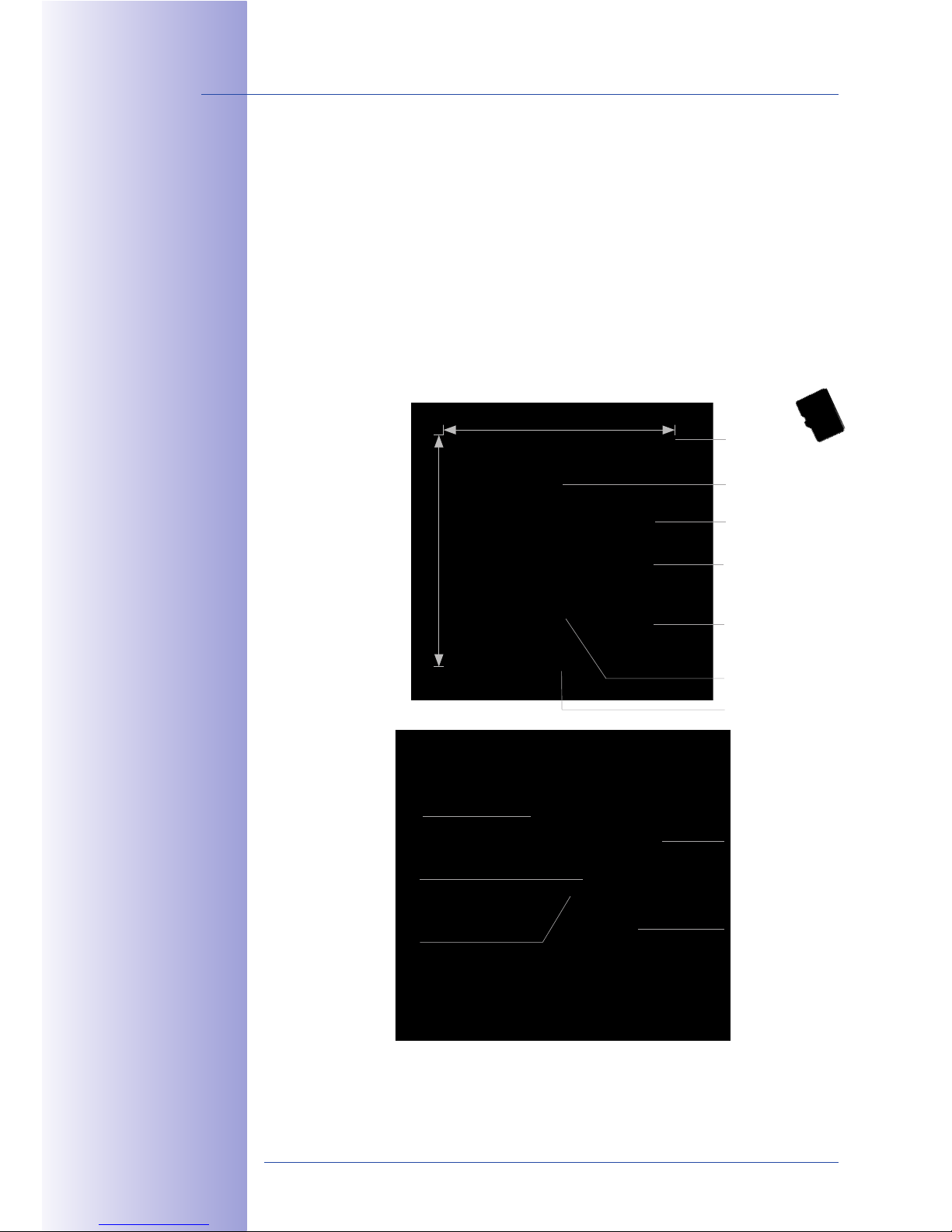
T24-DoorMaster
• Open door, doorbell on/o
• Status LEDs for door and messages
• Backup power supply with battery
• Connection of door opener and sensors
T24-Info2wire+ Indoor Unit
• Remote station for unit in the info module
• Data transfer and power supply via
two-wire connection
• Alternative to standard Ethernet cable
• Power input with PoE+ switch or
48-57 V DC, 600 mA power supply unit
VoIP video phone (ground floor remote station)
• Two-way video communication, open door,
turn light on/o
• Operate camera (including image correction)
• Monitor door status (open/closed/locked)
• Recording and event search
• Voice mailbox player
Standard PC (remote station)
• Free MOBOTIX MxEasy software
• T24 configuration and operation
•
All functions including two-way video communication
• Connection via Ethernet/WLAN
_<"/*< *11$22 "7$# *'4
K'+$#'$+ 1"''$1+&"'
Network connection
Connection to switch, router
PoE switch/PoE+ with Mx2wire+
Door contact
Door opener
Door lock switch
Internet connection
Worldwide access
Network connection
Connection to switch, router
Page 24
24/148
© MOBOTIX AG • Security-Vision-Systems • Made in Germany
www.mobotix.com • [email protected]
T24 System Manual Part 1: System Overview
1 SYSTEM OVERVIEW
1.1 Outdoor Station
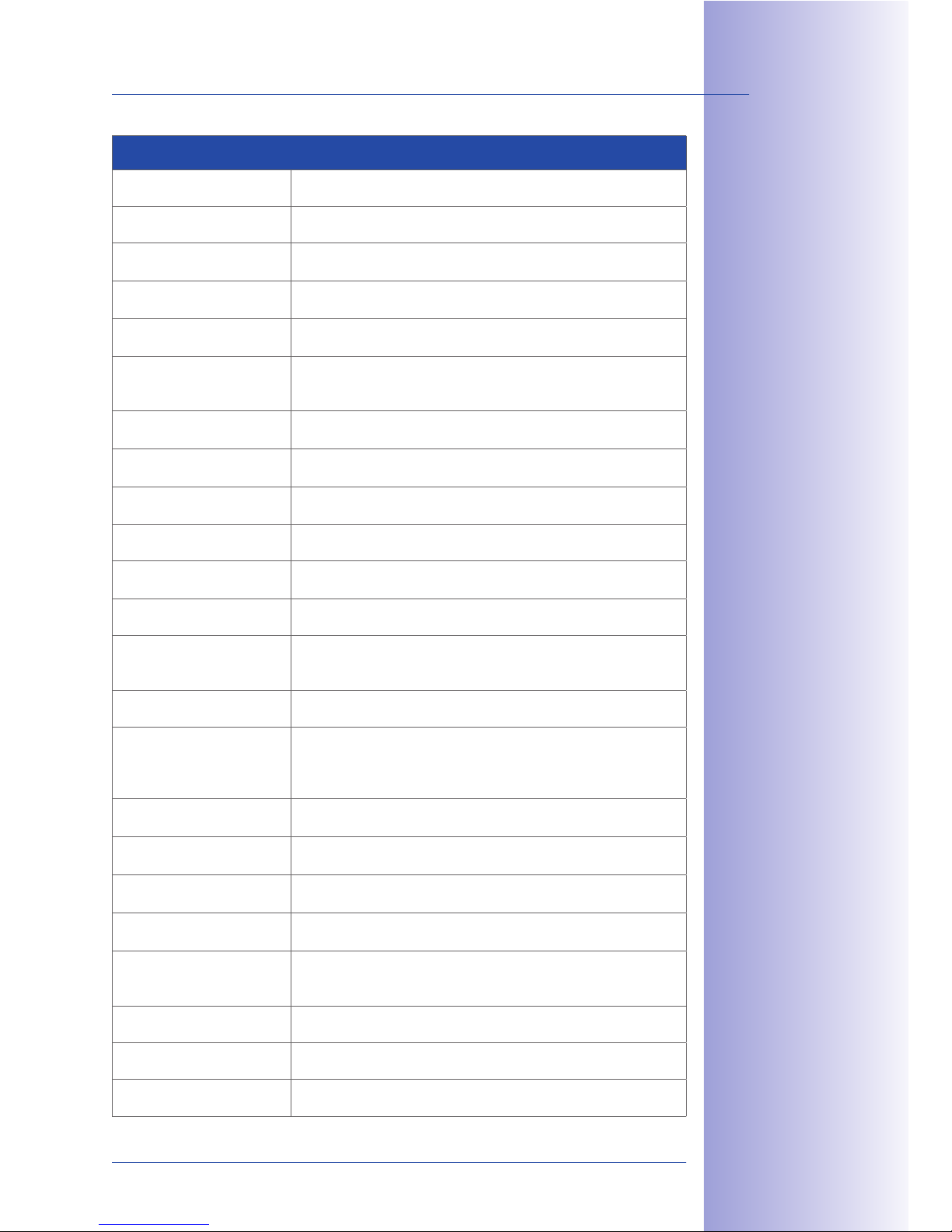
1.1.1 Hemispheric Camera T24-CamCore
The hemispheric camera with its fisheye lens (for a 360° panorama view) and integrated
live image correction boasts a high-resolution 3.1 megapixel color sensor (or megapixel
black and white sensor), speaker, microphone and 4 GB data storage for approx. 250
one-minute video clips or 60,000 VGA images.
MxBus connector
Mini USB (for future
expansion modules)
Bayonet catch
LEDs
Speaker
Integrated
4 GB MicroSD card
Light button
Door bell
Lens
Microphone
Network connection
Seal
99 mm
99 mm
Page 25
25/148
Outdoor Station
© MOBOTIX AG • Security-Vision-Systems • Made in Germany
www.mobotix.com • [email protected]
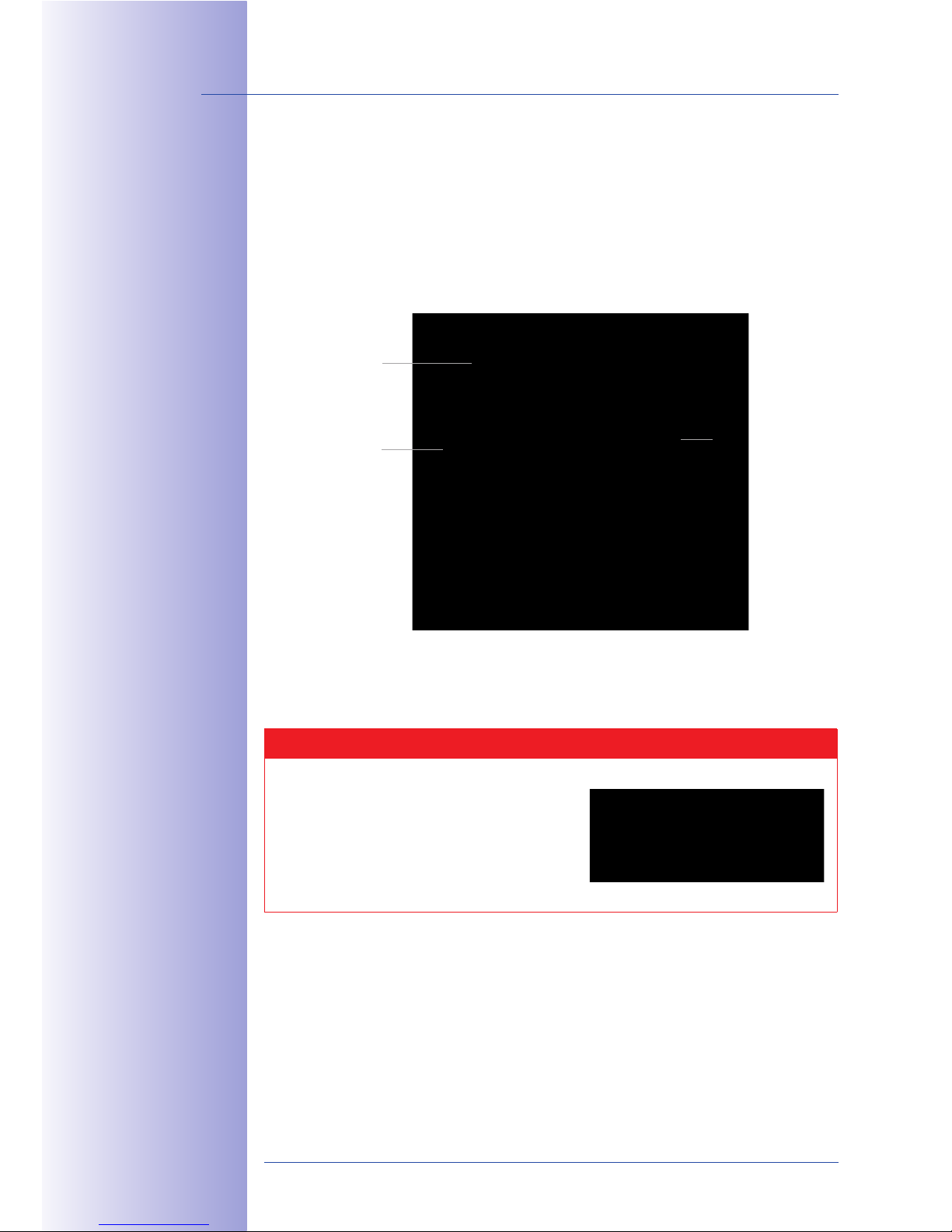
Technical Specifications: T24-CamCore
Model versions Secure, Secure-Night (T24M-Sec-Night-N11)
Lens options L11 Hemispheric 360°
Sensitivity
Color version: 1 lux (t = 1/60 s), 0.05 lux (t = 1/1 s)
B/W version: 0.1 lux (t = 1/60 s), 0.005 lux (t = 1/1 s)
Image sensor 1/2” CMOS, progressive scan
Max. image resolution
Color: 2,048 x 1,536 (3MEGA)
B/W: 1,280 x 960 (MEGA)
Image formats
Selectable image formats (160 x 120 to 2,048 x 1,536/color);
PTZ view, Quad view, Panorama widescreen image,
Double Panorama, Panorama Focus with 3 views
Max. frame rate (M-JPEG)
(live/recording)
VGA: 25 fps, TV-PAL: 18 fps, MEGA: 8 fps, 3MEGA: 4 fps
Max. video stream (MxPEG)
(live/recording/audio)
VGA: 30 fps, TV-PAL: 30 fps, MEGA: 30 fps, 3MEGA: 20 fps
Image compression MxPEG, M-JPEG, JPEG, H.263 and H.264 (only with Video VoIP)
Internal DVR
4 GB MicroSD card (camera-internal recording, max. 32 GB usable)
External video storage
Directly on NAS and PC/Server without additional
recording software
Software (included) MxEasy video management software
Image processing
Backlight compensation, automatic white balance,
image correction (incl. panorama image correction),
video sensor (motion detection)
Virtual PTZ Digital pan/tilt/zoom, continuous 8x zoom
Alarm/events
Triggering of events through integrated multiple-window
motion detection, temperature sensor, notification over email,
FTP, IP telephony (VoIP, SIP), visual/acoustic alarm,
pre- and post-alarm images
Audio Microphone, speaker, G.711, lip-synchronous sound
Video telephony
VoIP/SIP, two-way video communication, remote controlling with
key code, event notification
Security
User/group management, HTTPS/SSL, IP address filter,
IEEE 802.1x, intrusion detection, digital image signature
Certificates
EMV (EN50121-4, EN55022, EN55024, EN61000-6-2, FCC part15B,
AS/NZS3548)
Power supply
Power over Ethernet (PoE in accordance with IEEE802.3af): PoE
class variable depending on operating mode; power consumption:
typically 3 W; via PoE switch/MOBOTIX PoE adapter/Mx2wire+
Operating conditions IP65 (DIN EN 60529), -30°C to + 50°C (-22°F to +122°F)
Interfaces MxBus, USB, Ethernet
Dimensions (W x H) 99 mm x 99 mm
85$ 1*)$#* &2 *<2"
*7*&<*/<$ &' * 7$#2&"'
-&+5 * /<*16 *'; -5&+$
2$'2"# P$0+#$)$<4
<&@5+?2$'2&+&7$ 2$'2"#Q
Page 26
26/148
T24 System Manual Part 1: System Overview
© MOBOTIX AG • Security-Vision-Systems • Made in Germany
www.mobotix.com • [email protected]
1.1.2 Ethernet Terminal Board T24-OPT-ETH
The ethernet terminal board T24-OPT-ETH is used to connect the door station for the T24
versions without Mx2wire+ technology. It securely connects the camera module with the
8 connected wires of the network patch cable via RJ45 connector (for installation, see
Chapter 2).
Caution
Only use original MOBOTIX cables to connect the camera.
Standard cables purchased from other suppliers
do not meet the necessary specifications for proper
fastening (not impermeable/weatherproof).
Ethernet connector
with PoE supply
Cable sheath
contact
Connector for the
special patch cable
of the T24-CamCore
89:?M[8?`8B
Ethernet patch cable
Page 27

27/148
Outdoor Station
© MOBOTIX AG • Security-Vision-Systems • Made in Germany
www.mobotix.com • [email protected]
The Ethernet terminal board is screwed on to the housing (on-wall or in-wall) behind the
camera module.
a<+$#'*+&7$<4A +5$
$0+$';$; +$#)&'*<
/"*#; 89:?M[8?KM
1*' /$ 32$; +" 1"''$1+
$0+$#'*< ;$7 1$2A
2315 *2 * ;""#/$<<
Page 28
28/148
T24 System Manual Part 1: System Overview
© MOBOTIX AG • Security-Vision-Systems • Made in Germany
www.mobotix.com • [email protected]
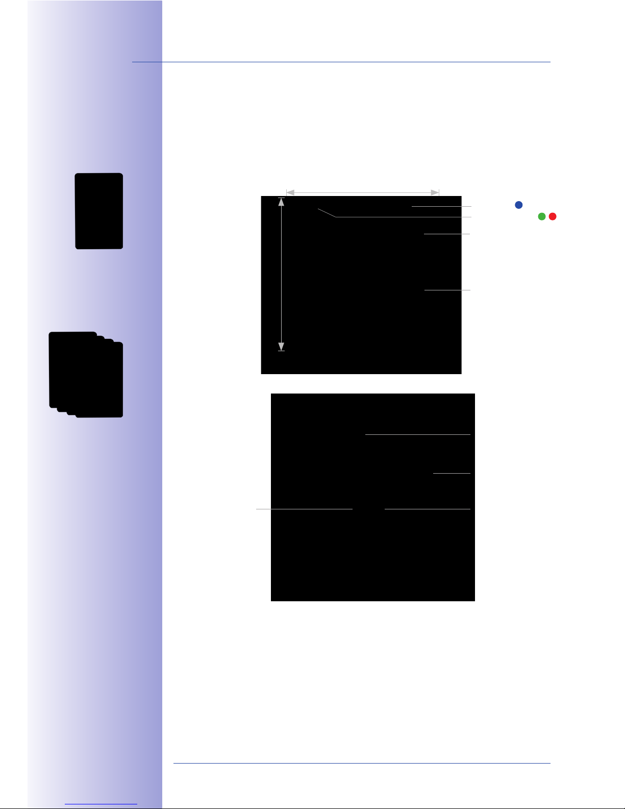
1.1.3 Access Module T24-KeypadRFID
This module is used for keyless and scheduled access to the house or building with an
access PIN or RFID transponder card.
Voice messages can also be spoken and played back using the keypad.
IO terminal
LED (blue)
LED (green, red)
Open door, messages,
doorbell
10-key keypad
+ 2 function keys
Sealing plug
Seal
MxBus terminal
99 mm
99 mm
View with housing cover removed
K'1<3;$; &' ;$<&7$#4,
a' a;)&' L=KC 1*#;
("# +5$ ">$#*+&"'
*'; *1+&7*+&"'
"( 32$# 1*#;2
K'1<3;$; &' ;$<&7$#4,
D$7$#*< b2$# L=KC
1*#;2 ("# ;""# ">$' '@
*'; 7"&1$ )*&</"0 *11$22
a;;&+&"'*< 1*#;2
Pa;) 'Rb2$#Q 1*'
/$ "#;$#$; (#")
!MNM8KO
Page 29
29/148
Outdoor Station
© MOBOTIX AG • Security-Vision-Systems • Made in Germany
www.mobotix.com • [email protected]
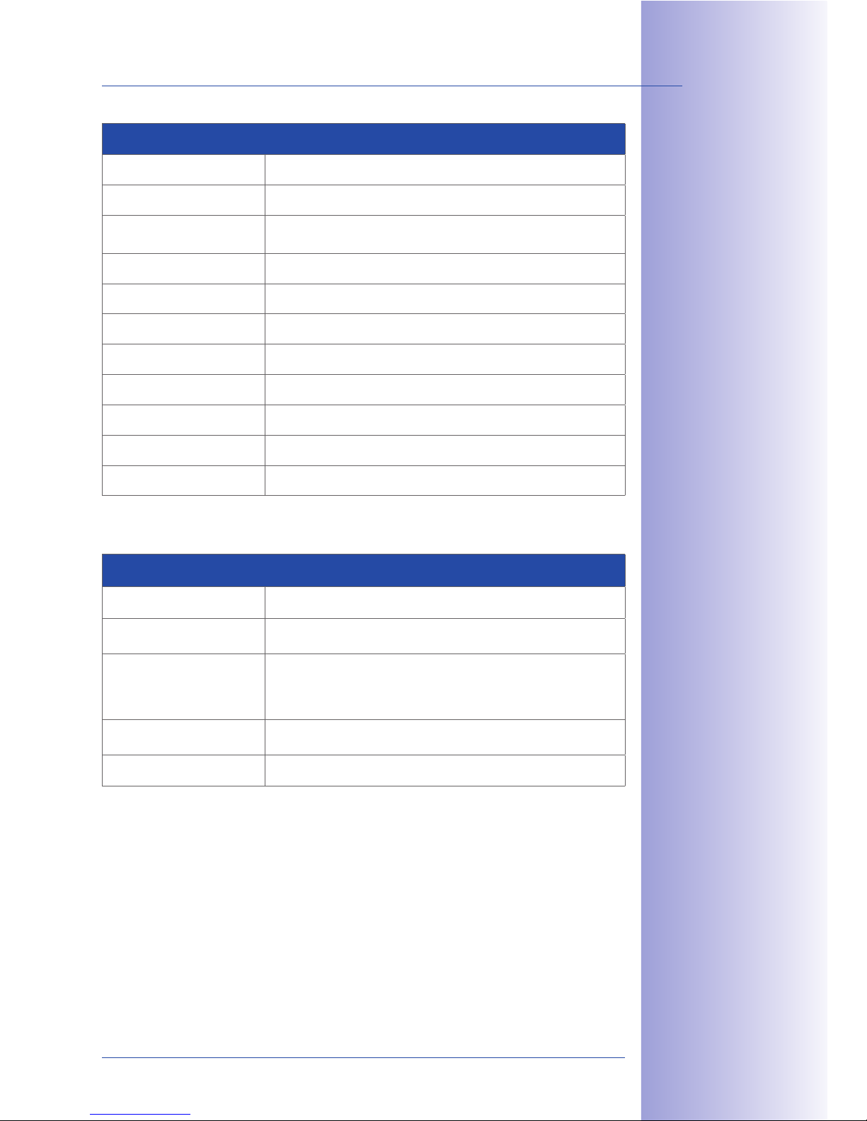
Technical Specifications: T24-KeypadRFID
Functions Keyless access using RFID card and PIN
Interface MxBus
User interfaces
RFID (13.56 MHz, Mifare DESFire EV1), illuminated keys,
acoustic feedback
Inputs 2 galvanically separated inputs (AC/DC, self-powered, up to 50 V)
Outputs 1 isolated relay output (AC/DC, -50 V/60 W/2 A)
Sensors Illumination sensor
Protection class IP65 (DIN EN 60529)
Operating temperature -30°C to +50°C / -22°F to +122°F (DIN EN 50125)
Power supply MxBus
Power consumption typically 1 W
Dimensions (W x H) 99 mm x 99 mm
Technical Specifications: Terminals Used On The Keypad
Cable cross-section, fixed min. 0.14 mm²/max. 0.5 mm²
Cable cross-section,
flexible
min. 0.2 mm²/max. 0.5 mm²
Cable cross-section,
flexible, with wire-end
sleeves without plastic
sleeves
min. 0.25 mm²/max. 0.5 mm²
Cable cross-section
AWG/kcmil
min. 24/max. 20
AWG according to UL/CUL min. 26/max. 20
K' +5$ 1*2$ "( * >"-$#
(*&<3#$A +5$ 6$4>*; *';
+5$ ;""# ">$'$# *#$
23>>< $; -&+5 >"-$#
(#") +5$ /*++$#4 "(
+5$ 89:?C""#!*2+$#
L$1"))$';$;
- #$ ;&*)$+$#,
G.J +" G.F ))
Page 30
30/148
T24 System Manual Part 1: System Overview
© MOBOTIX AG • Security-Vision-Systems • Made in Germany
www.mobotix.com • [email protected]
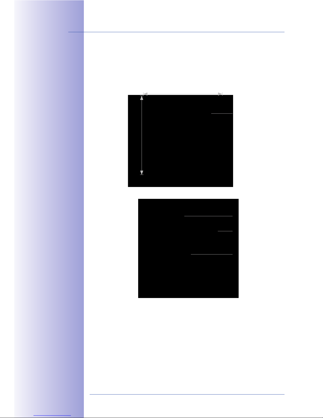
1.1.4 Info Module T24-Info
The standard info module provides the option to attach the house or building number
and/or name to the door station. The module is equipped with permanent backlighting
using energy-saving and long-lasting LED technology.
Info field can be labeled
(behind cover)
Sealing plug
Seal
MxBus terminal
(power supply for the LED)
99 mm
99 mm
View with housing cover removed
Page 31
31/148
Outdoor Station
© MOBOTIX AG • Security-Vision-Systems • Made in Germany
www.mobotix.com • [email protected]
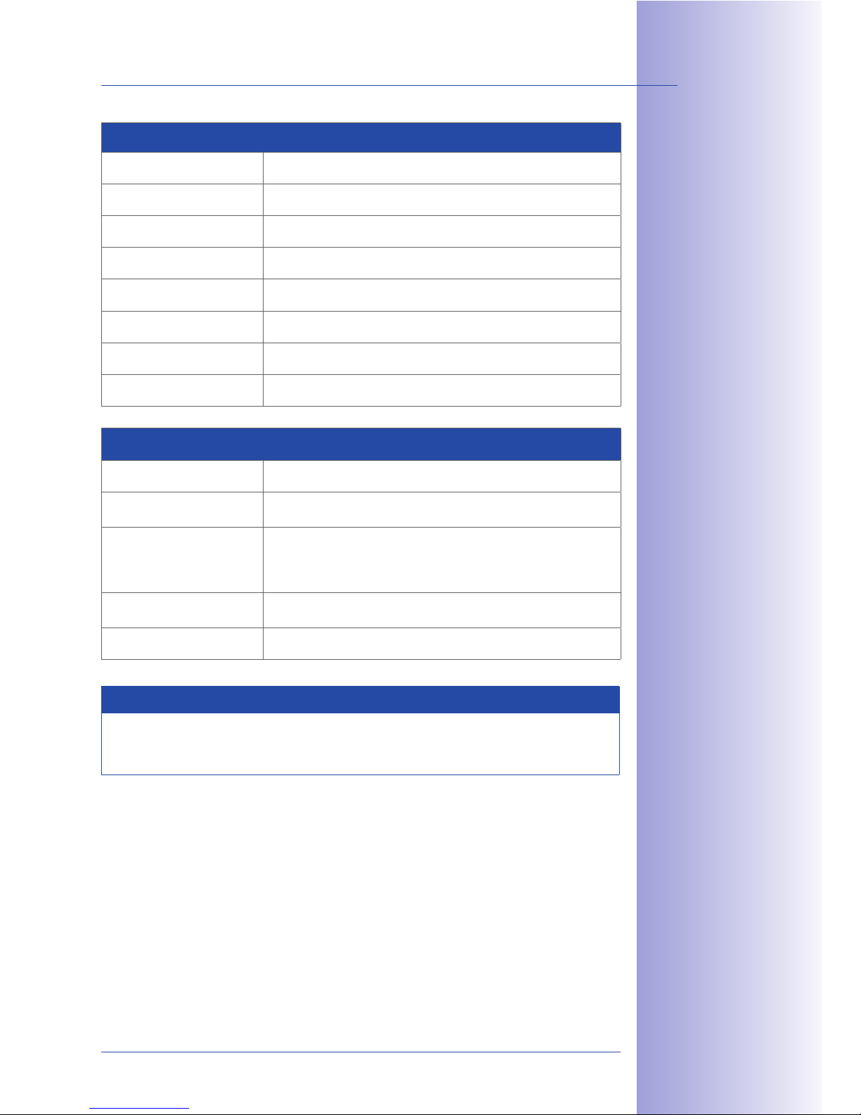
Technical Specifications: T24-Info
Functions Information for visitors on nameplate (name, street number, etc.)
Interfaces MxBus
User interfaces Backlit, printable foil (UV-protected)
Protection class IP65 (DIN EN 60529)
Operating temperature -30°C to +50°C / -22°F to +122°F (DIN EN 50125)
Power supply MxBus
Power consumption typically 0.2 W
Dimensions (W x H) 99 mm x 99 mm
Technical Specifications: Terminals Used On The Info Module
Cable cross-section, fixed min. 0.14 mm²/max. 0.5 mm²
Cable cross-section,
flexible
min. 0.2 mm²/max. 0.5 mm²
Cable cross-section,
flexible, with wire-end
sleeves without plastic
sleeves
min. 0.25 mm²/max. 0.5 mm²
Cable cross-section
AWG/kcmil
min. 24/max. 20
AWG according to UL/CUL min. 26/max. 20
Note On Labeling
You will find some PDF templates, which you can print out yourself, on the MOBOTIX
website (www.mobotix.com).
L$1"))$';$;
- #$ ;&*)$+$#,
G.J +" G.F ))
Page 32
32/148
T24 System Manual Part 1: System Overview
© MOBOTIX AG • Security-Vision-Systems • Made in Germany
www.mobotix.com • [email protected]
1.1.5 T24-Info2wire+ (Info Module With Indoor Unit)
T24-Info2wire+ Info Module
The info module with Mx2wire+ technology, combined with a second Mx2wire+ unit to
be mounted inside the building, oers users not only the standard info module functions
but also the option to connect and supply power to the door station via two-wire
cabling instead of a network cable (see Section 1.1.4). Advantage: Simple and cost-eective
installation thanks to reuse of already existing two-wire cabling.
Info field can be labeled
(behind cover)
LED orange (data)
LED green (power supply)
Sealing plug
Seal
48 V DC (optional additional
power supply)
Ethernet (PoE injector)
99 mm
99 mm
Two-wire
connection
View with housing cover removed
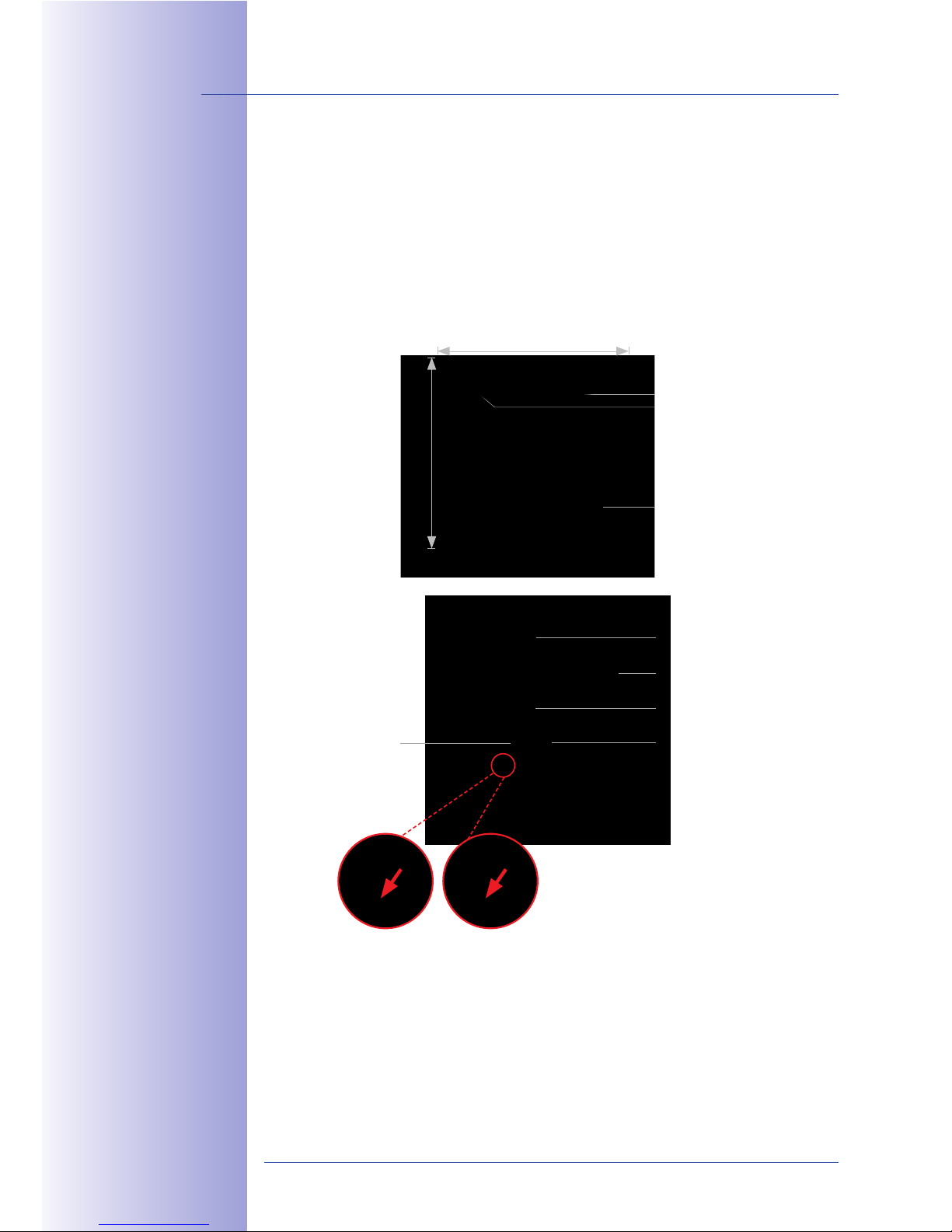
To activate the LED illumination of the module,
you need to cautiously remove the small
black jumper on the circuit board (using
tweezers or small pliers) before mounting
the module itself.
LED illumination
activated
LED illumination
deactivated
a ["`U 2-&+15 "#
*' $0+$#'*< 7"<+*@$
1"''$1+&"' P:F?cX ^ C\A
JGG )aQ 1*' /$ 32$;
85$ +-" 2+*+32 d`C2
P"#*'@$A @#$$'Q *#$
*1+&7*+$; ("# +$2+
>3#>"2$2 -&+5 ' +5$
]#2+ Ec )&'3+$2 *(+$#
+5$ &'(" )";3<$ 5*2
/$$' >"-$#$; 3>
Page 33
33/148
Outdoor Station
© MOBOTIX AG • Security-Vision-Systems • Made in Germany
www.mobotix.com • [email protected]
Technical Specifications: T24-Info2wire+ Info Module
Data transfer rate Up to 50 Mbps net (depending on distance)
Interfaces
Ethernet (PoE injector), Mx2wire+ indoor unit, 48-57 V DC, 600 mA
(optional additional supply)
Certificates
EMV (EN55022, EN55024, EN61000-6-1, FCC part15B, AS/NZS3548)
Protection class IP65 (DIN EN 60529)
Operating temperature -30°C to +50°C / -22°F to +122°F (DIN EN 50125)
Connecting wire thickness Cable cross-section 0.14 to 2.5 mm
2
, diameter 0.4 to 1.6 mm
Dimensions (W x H) 99 mm x 99 mm
Note On Labeling
You will find some PDF templates, which you can print out yourself, on the MOBOTIX
website (www.mobotix.com).
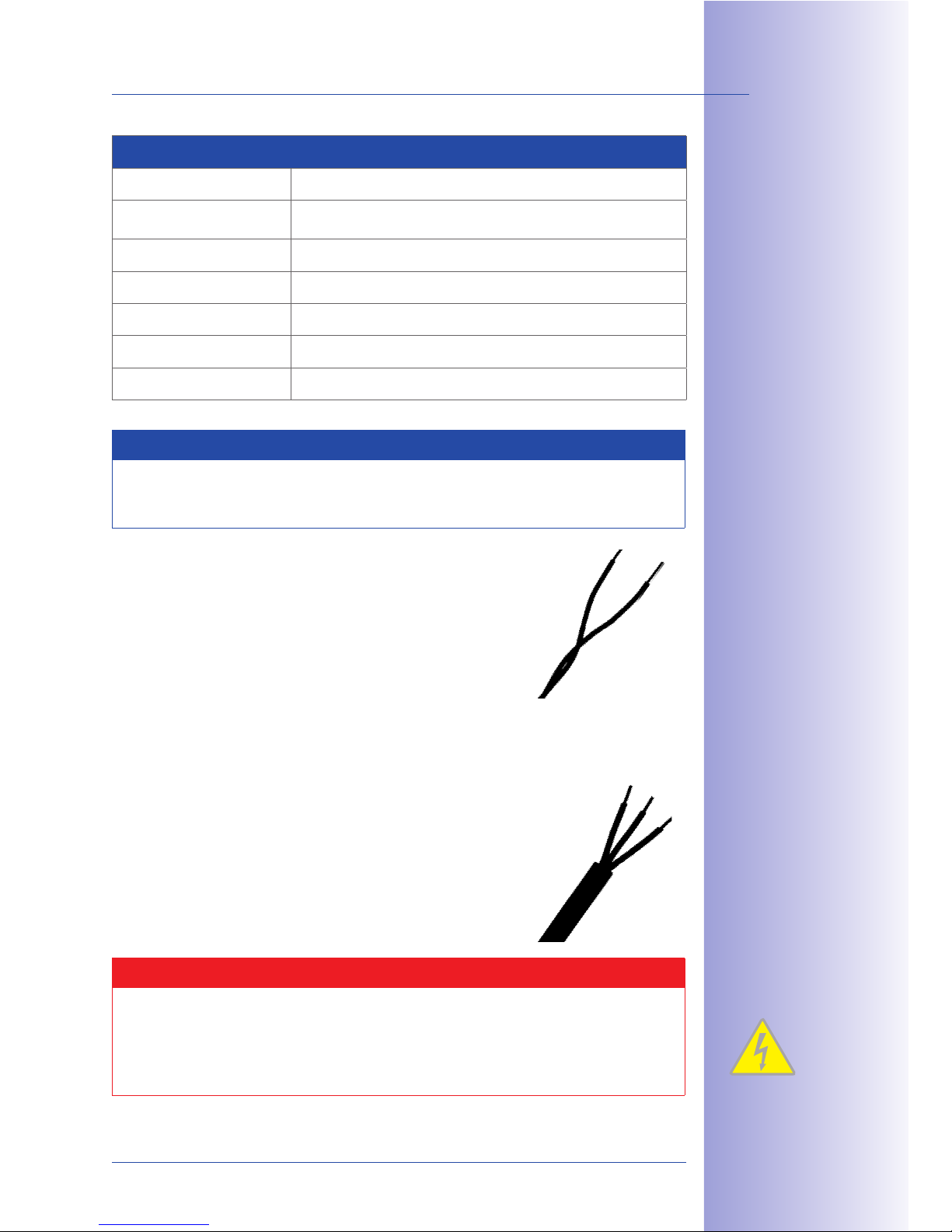
Standard Two-Wire Cabling (Already Laid In Buildings)
Analog Telephone Line Or Bell Wire
• Cable type: JY, A2Y and YR (telephone and
low-voltage cable)
• Very good availability in buildings
• Core diameter 0.6 to 0.8 mm
• Range (at 50 Mbps): 100 m (0.6 mm), 200 m (0.8 mm)
Power Line (Should No Longer Be Live)
• Cable type: NY (installation cable)
• Widespread availability of cables
• Cables must be disconnected from the power supply!
• Wire cross-section max. 1.5 mm
2
• Range (at 40 Mbps): 300 m
Safety Warning
Use this product in compliance with the applicable legal regulations. Electrical systems
and equipment may only be set up, changed and maintained by a qualified electrician
or under the management and supervision of a qualified electrician in accordance
with electrotechnical regulations.
Page 34

34/148
T24 System Manual Part 1: System Overview
© MOBOTIX AG • Security-Vision-Systems • Made in Germany
www.mobotix.com • [email protected]
T24-Info2wire+ Indoor Unit
An Mx2wire+ set always consists of two devices that communicate with one another. For
this reason, the necessary unit to connect to the network and to supply power is included
with the Mx2wire+ info module in the door station.
LED orange (data)
LED green (power supply)
RJ45 network connection
Two-wire connection
(T24-Info2wire+
info module)
80 mm
80 mm
48-57 V DC
(optional
additional
power supply)
["-$# 23>><4 -&+5
["`U 2-&+15 "#
:F?cX ^ C\A JGG )a
P>"-$# 23>><4 3'&+Q
Page 35
35/148
Outdoor Station
© MOBOTIX AG • Security-Vision-Systems • Made in Germany
www.mobotix.com • [email protected]
Technical Specifications: T24-Info2wire+ Indoor Unit
Data transfer rate Up to 50 Mbps net (depending on distance)
Interfaces
Ethernet (PoE Class 3), Mx2wire+ info module, 48-57 V DC, 600
mA (optional additional supply)
Certificates
EMV (EN55022, EN55024, EN61000-6-1, FCC part15B, AS/NZS3548)
Power supply
PoE+ (PoE IEEE802.3af), performance-related 7 Watt
own consumption or 48-57 V DC, 600 mA SELV power supply unit
Status display
LED green (network connection, power supply),
LED orange (data transfer via AB conductor is active,
door station connected)
Operating conditions -30°C to +50°C / -22°F to +122°F
Connecting wire thickness Cable cross-section 0.14 to 2.5 mm
2
, diameter 0.4 to 1.6 mm
Dimensions (W x H x D)
80 mm x 80 mm x 38 mm (in-wall version),
80 mm x 80 mm x 45 mm (on-wall version)
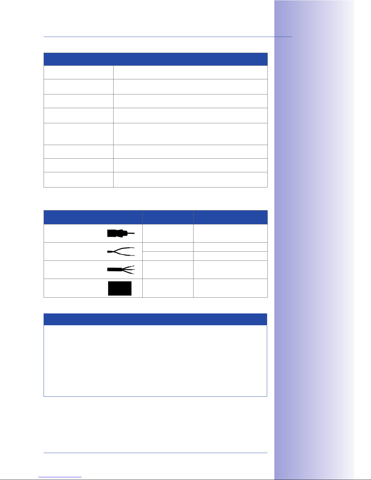
Max. Cable Lengths Of Usable Cable Types As Two-Wire Cable Of A T24 Door Station
Cable type Cable thickness Max. cable length
Antenna or
coaxial cable
0.6 mm (inner core) 100 m (50 Mbps)
Telephone line/
bell wire
0.6 mm 100 m (50 Mbps)
0.8 mm 200 m (50 Mbps)
Installation cable
1.5 mm
2
300 m (40 Mbps)
Network
installation cable
Cat7 500 m (45 Mbps)
Notes
The Mx2wire+ set consisting of two units (info module and indoor unit) contains all
the components required to establish an Ethernet connection via a two-wire cable.
Please note that the two Mx2wire+ units are matching pairs and preconfigured
at the factory. The use of a dierent Mx2wire+ unit that was not supplied in the
original packaging is therefore technically not possible. In case of a defect, both units
must always be exchanged for a new Mx2wire+ pair that has been configured by
MOBOTIX.
!09-&#$U >*&# ("# 89:,
89:?K'("9-&#$U &'("
)";3<$ -&+5
&';""# 3'&+
Page 36
36/148
T24 System Manual Part 1: System Overview
© MOBOTIX AG • Security-Vision-Systems • Made in Germany
www.mobotix.com • [email protected]
1.1.6 Housing And Module Frames
The robust IP Video Door Station can be installed in both on-wall and in-wall systems,
it is weatherproof (IP 65) and cannot be stolen. The system consists of a housing and a
frame. The frame for mounting the modules is simply screwed on to the housing used.
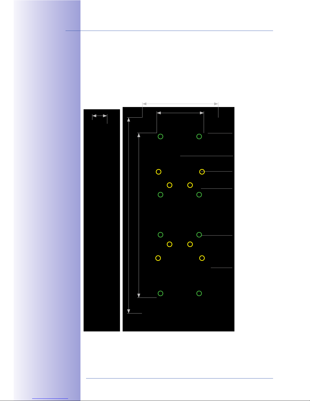
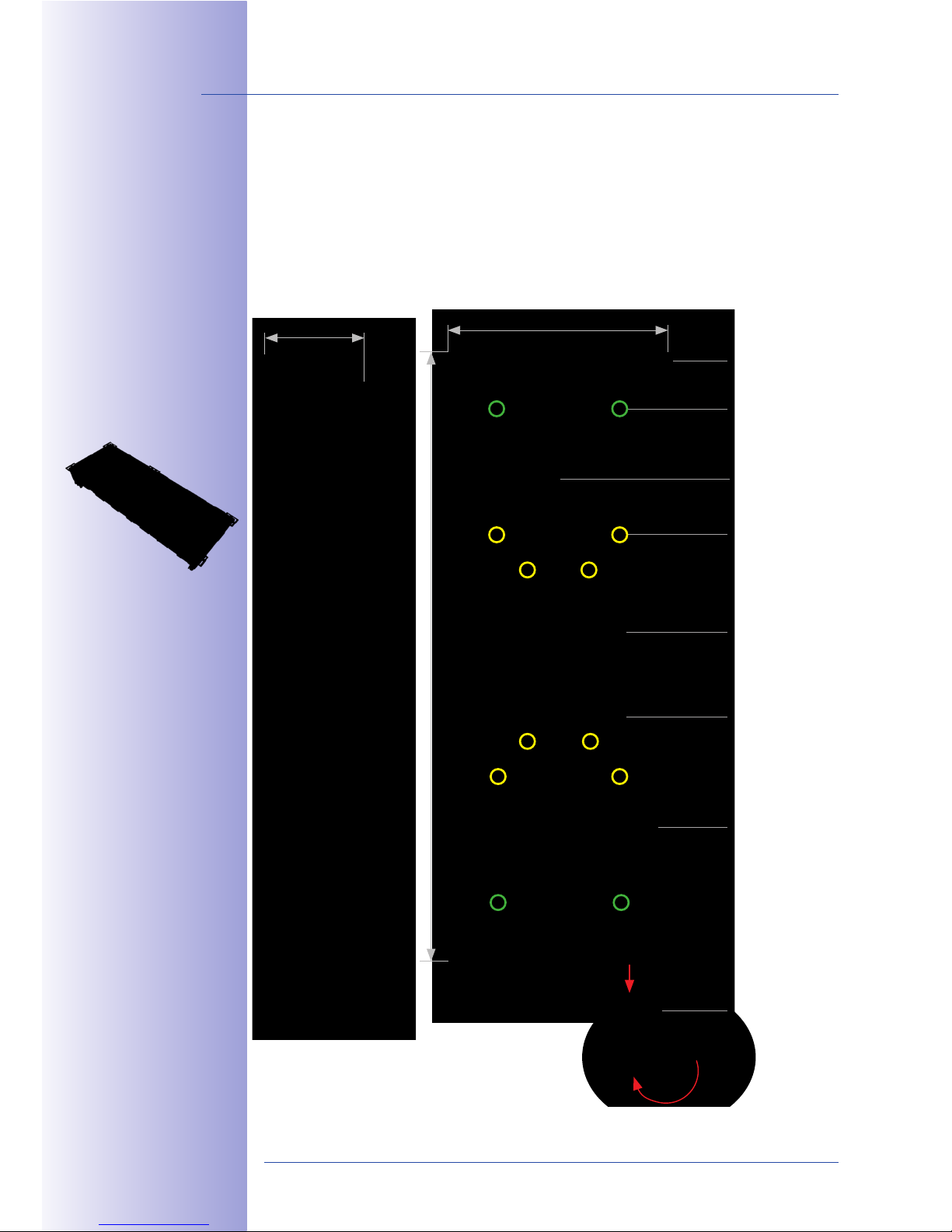
On-Wall Housing (Fig. Triple Housing)
Mounting points for terminal
board or IO module (3x)
Wall mount (4x)
Cable guide (6x)
Mounting points
for cable binders
(8x, marked yellow)
Mounting points
for module frames
(8x, marked green)
Mounting points for seal
126 mm
80 mm
327 mm (double housing: 227 mm, single housing: 138 mm)
31 mm
282 mm (double housing: 182 mm, single housing: 90 mm)
Page 37
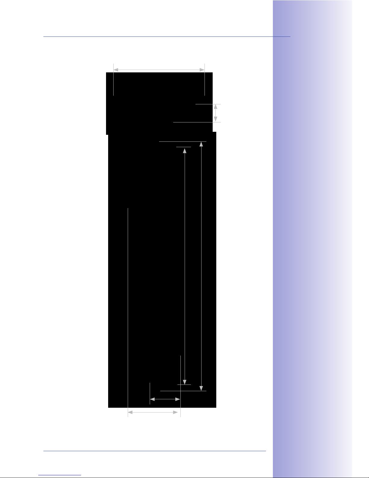
37/148
Outdoor Station
© MOBOTIX AG • Security-Vision-Systems • Made in Germany
www.mobotix.com • [email protected]
131 mm
26 mm
76 mm
327 mm (double housing: 227 mm, single housing: 138 mm)
333 mm (double housing: 233 mm, single housing: 143 mm)
44 mm
Page 38
38/148
T24 System Manual Part 1: System Overview
© MOBOTIX AG • Security-Vision-Systems • Made in Germany
www.mobotix.com • [email protected]
In-Wall And Cavity Housing (Fig. Triple Housing)
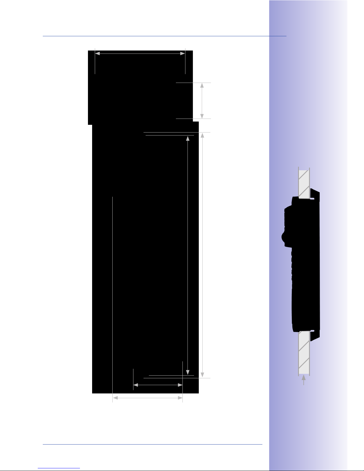
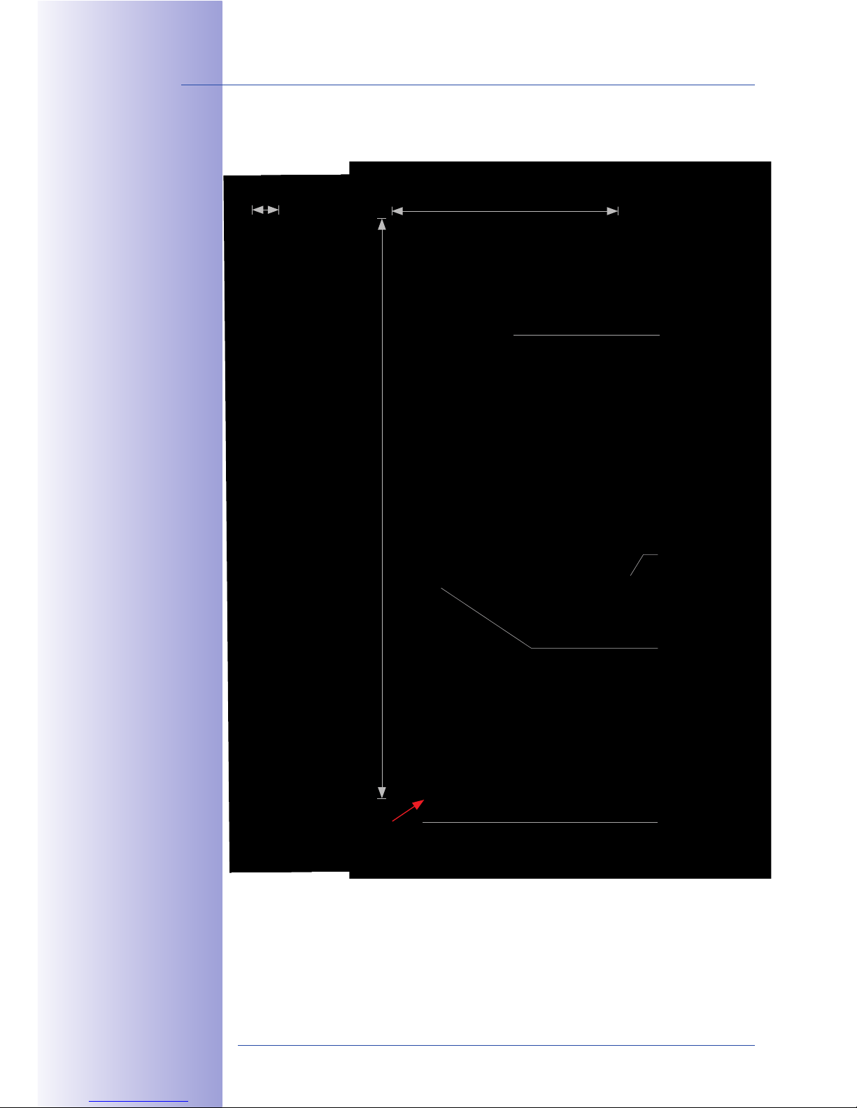
The blue housing is firmly connected to the subsurface or brick work. It can also be used
to ensure easy installation in cavities: Drill opening, position housing and screw tightly
in place; the retaining wings, which automatically swing out, secure the housing, while
the plastic bars at the edge of the housing prevent it from sliding into the cavity.
52 mm
Mounting points for terminal
board or IO module (3x)
Plastic bars (6x)
Cable guide (14x)
Mounting points
for cable binders
(8x, marked yellow)
Mounting points
for module frames
(4x, marked green)
Do not use the four
red holding fixtures
for module frames
Mounting points for seal
318 mm (double housing: 218 mm, single housing: 129 mm)
117 mm
Retaining wings
for cavity installation (4x)
85$ '2$#+ >#$7$'+2
+5$ &'?-*<< 5"32 '@
(#") @$++ '@ ;&#+4
"# /$ '@ ;$("#)$;
;3# '@ &'2+*<<*+&"'
85$ #$V3&#$; &'+$@#*+&"'
">$' '@ 5*2 +5$
("<<"- '@ ;&)$'2&"'2
P-&;+5 0 5$&@5+Q,
D&'@<$ 5"32 '@,
EEX 0 E9Y ))
C"3/<$ 5"32 '@,
EEX 0 9EF ))
8#&><$ 5"32&'@,
EEX 0 IEF ))
Page 39
39/148
Outdoor Station
© MOBOTIX AG • Security-Vision-Systems • Made in Germany
www.mobotix.com • [email protected]
[$#)&22&/<$ -*<< +5&16'$22
("# 1*7&+4 &'2+*<<*+&"',
)&'. X ))R)*0. 9X ))
Xe9X ))
131 mm
50 mm
97 mm
318 mm (double housing: 218 mm, single housing: 129 mm)
333 mm (double housing: 233 mm, single housing: 143 mm)
69 mm
Page 40
40/148
T24 System Manual Part 1: System Overview
© MOBOTIX AG • Security-Vision-Systems • Made in Germany
www.mobotix.com • [email protected]
Module Frame (Fig. Triple Frame)
Installation of module
Connection of
anti-theft protection
Activation of
anti-theft protection
333 mm
131 mm
18 mm
Key to release the
modules from the
frame (press upwards;
only possible after
anti-theft protection
has been deactivated)
Page 41
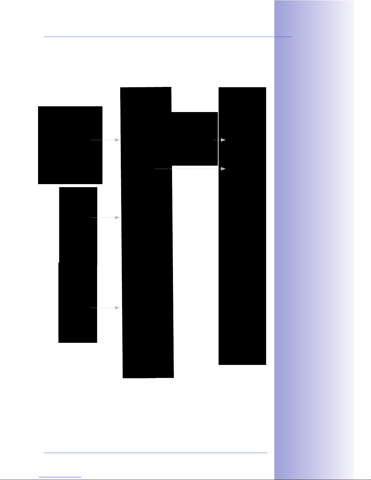
41/148
Outdoor Station
© MOBOTIX AG • Security-Vision-Systems • Made in Germany
www.mobotix.com • [email protected]
f `+5$#'$+ +$#)&'*<
/"*#; 89:?M[8?`8B &2
'"+ #$V3&#$; -5$' 32&'@
!09-&#$U +$15'"<"@4
T24-Modules
T24-CamCore,
T24-KeypadRFID,
T24-Info/T24-Info2wire+
Frame
With integrated
anti-theft
protection
Housing
On-wall or
in-wall
housing
Terminal board*
Ethernet terminal
board or
IO module
Page 42
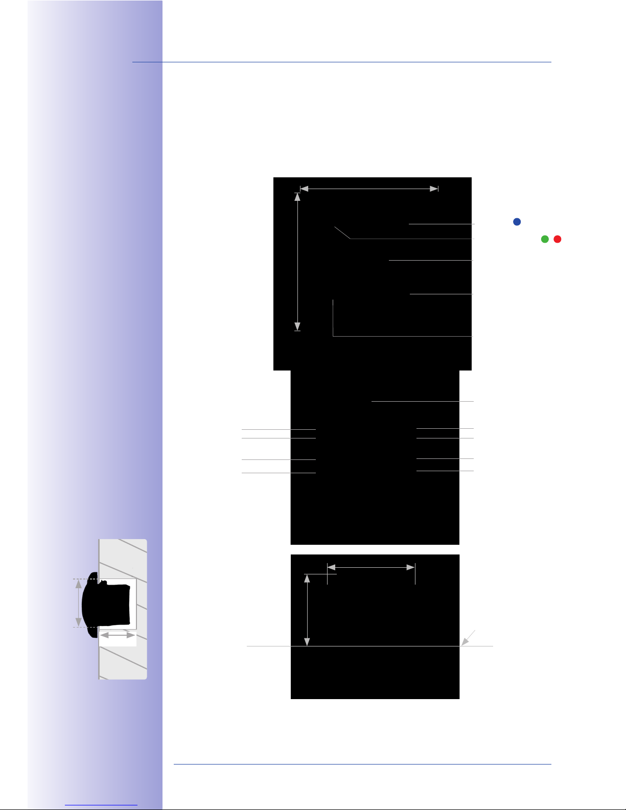
42/148
T24 System Manual Part 1: System Overview
© MOBOTIX AG • Security-Vision-Systems • Made in Germany
www.mobotix.com • [email protected]
1.2 T24-DoorMaster
The T24 may be coupled with the T24-DoorMaster with internal access code memory,
making it impossible to open the door by forcibly removing the system and bypassing the
connecting cable.
JX ))
g JF ))
80 mm
80 mm
LED blue
Door opener (emergency
unlocking in the event
of a power failure)
Volume of doorbell
Speaker
Connector
for battery pack
OUT IN -
IN 2+
IN 1+
OUT 1+
OUT 2+
MX +
MX -
41.5 mm
51 mm
Wall
LED (green, red)
!&'&)3) )"3'+&'@
; )$'2&"'2,
Page 43
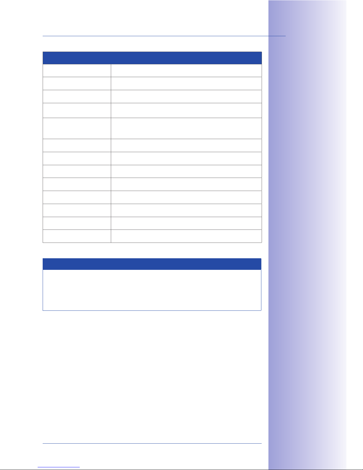
43/148
T24-DoorMaster
© MOBOTIX AG • Security-Vision-Systems • Made in Germany
www.mobotix.com • [email protected]
Technical Specifications: T24-DoorMaster
Functions Security door opener with internal access code memory
Interfaces MxBus (max. 50 m distance to door station)
User interfaces 2 status LEDs, 2 function buttons, integrated speaker (doorbell)
Inputs
2 galvanically separated inputs with shared ground connection
(AC/DC, self-powered – 50 V)
Outputs
1 isolated relay output (AC/DC, 24 V/1 A) or
1 connector for standard door opener (6-12 V AC)
1 output for MOBOTIX anti-theft protection (12 V DC)
Protection class IP 20 (DIN EN 60529)
Operating temperature -5°C to +40°C / +23°F to +104°F (DIN EN 50125)
Power supply MxBus
Power consumption typically 1 W
Output max. 10 W
Switch time max. 5 s
Connecting wire thickness Cable cross-section 0.14 to 2.5 mm
2
, diameter 0.4 to 1.6 mm
Dimensions (W x H x D) 80 mm x 80 mm x 41.5 mm
Note
The battery pack supplies the electrical door opener and, in the event of a power
failure, the keypad, which continues to guarantee that the door can be unlocked
multiple times. For installations in living areas, the T24-DoorMaster functions also
as a doorbell.
Supported Door Versions
An electrically-operated standard door opener (6 to 12 V AC, min. nominal resistance
10 ohm, no support for closed-circuit current function) can be connected directly to the
T24-DoorMaster and powered by its integrated battery pack. It is not necessary to connect
an additional power supply unit.
By integrating an additional power supply unit, door openers with up 24 V AC/DC
(max. 1 A) or a self-locking door lock (e.g., Mediator) can be connected.
!*0. 1*/<$ <$'@+5 ("#
!0N32 &2 cG )
85*'62 +" +5$ /*++$#4A
+5$ ;""# ">$'$# 1"'+ '3$2
+" (3'1+&"' &' +5$ $7$'+
"( * >"-$# (*&<3#$
Page 44
44/148
T24 System Manual Part 1: System Overview
© MOBOTIX AG • Security-Vision-Systems • Made in Germany
www.mobotix.com • [email protected]
1.3 Remote Stations
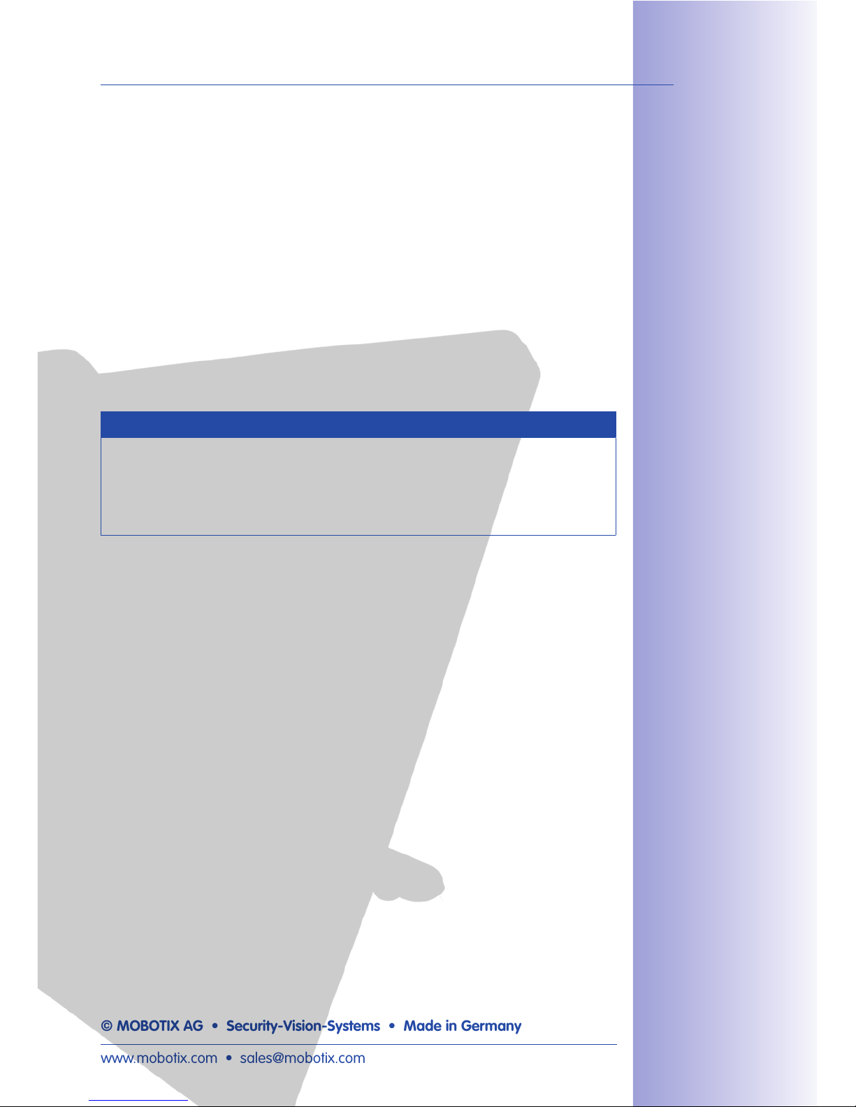
1.3.1 Grandstream IP Video Telephone GXV3140
MOBOTIX recommends the GXV3140 from Grandstream as a remote video station for the
T24 door station. This modern IP video telephone is based on the world standard in
telephony, VoIP/SIP with H.264, and provides a large color LCD display with excellent
image quality. The device is conveniently operated via a MOBOTIX user menu.
N*2 1 89: (3'1+&"'2
1*' *<2" /$ 1"'+#"<<$;
32&'@ +5$ >5"'$ 6$42
Display
Connector for
telephone receiver
Power supply
Network
connection 1
Video output
Audio output
USB
Network
connection 2
SD card slot
Page 45
45/148
Remote Stations
© MOBOTIX AG • Security-Vision-Systems • Made in Germany
www.mobotix.com • [email protected]
Extensive Multimedia Facilities
The GXV3140 from Grandstream includes important features such as transfer, hold and
conference calling for use in a professional environment, in addition to numerous multimedia
functions. The full duplex speaker phone is equipped with an acoustic echo canceller for
noise suppression.
The integrated camera can be switched on or o at the touch of a button. Additional
multimedia features include: a multimedia player for data from a USB stick or SD card,
display of RSS feeds and access to Internet radio.
The device also includes two Fast Ethernet connectors, a USB port (for external keyboards
etc.) and an SD card slot, so you can easily transfer and use your own data with the phone.
The integrated 2.5 mm connector allows you to attach a headset, and the video images
can be displayed on an external monitor using the A/V jack.
Note
In principle, other IP video telephones (with H.264 and G.711) can also be used as a
T24 remote station. Due to the technical specifications of a particular device (display
size, audio functions, etc.), however, it cannot be guaranteed that all T24 remote
station functions of the Grandstream GXV3140 are available.
D$$ *<2",
---.@#*';2+#$*).1")
Page 46

46/148
T24 System Manual Part 1: System Overview
© MOBOTIX AG • Security-Vision-Systems • Made in Germany
www.mobotix.com • [email protected]
1.3.2 MxEasy Video Management Software
MOBOTIX provides the MxEasy software free of charge to configure and operate the T24 IP
Video Door Station with a network-enabled desktop or notebook computer. In principle, there
is no need for a computer to handle configuration or operation when there is a simple
application scenario (one door station only, IP video telephone as remote station).
MxEasy allows you to quickly and eciently implement and control a video security system
of 1 to 16 MOBOTIX cameras, making it the perfect choice for all small and mid-sized
surveillance systems and the T24 IP Video Door Station. The program automatically detects
all installed cameras/door stations - even in non-administered networks - and carries out
the initial configuration. You are not required to have an in-depth knowledge of network
technology.
MxEasy enables the user to conveniently control the most important functions of the
connected door station. Virtual zooming, panning and tilting in the live image is just as
easy as using the live two-way video communication with the visitor, opening the door or
activating recording. The video data recorded by the cameras can then be viewed and
exported in dierent formats, such as H.264, at a later time.
!0`*24 P(#$$ ;"-'<"*;
(#") ---.)"/"+&0.1")Q
Page 47

47/148
Remote Stations
© MOBOTIX AG • Security-Vision-Systems • Made in Germany
www.mobotix.com • [email protected]
Easy Operation
MxEasy is easy to understand and simple to use. Descriptions for each graphical button
(“tooltips”) are displayed automatically. The user interface was also optimized for use
with mobile devices and touch panels. Incorrect settings can be easily reversed using the
automatic backup feature.
Security
MxEasy provides you with four dierent access levels (Guest, User, Owner, Administrator),
allowing people with dierent levels of authorization to access the camera images. MxEasy
can be installed on several computers at the same time. Optional HTTPS encryption (using
certificates generated by the camera or created by the administrator) helps you to prevent
unauthorized users from accessing MxEasy.
Page 48
48/148
T24 System Manual Part 1: System Overview
© MOBOTIX AG • Security-Vision-Systems • Made in Germany
www.mobotix.com • [email protected]
1.4 Accessories
1.4.1 NPA-PoE Set
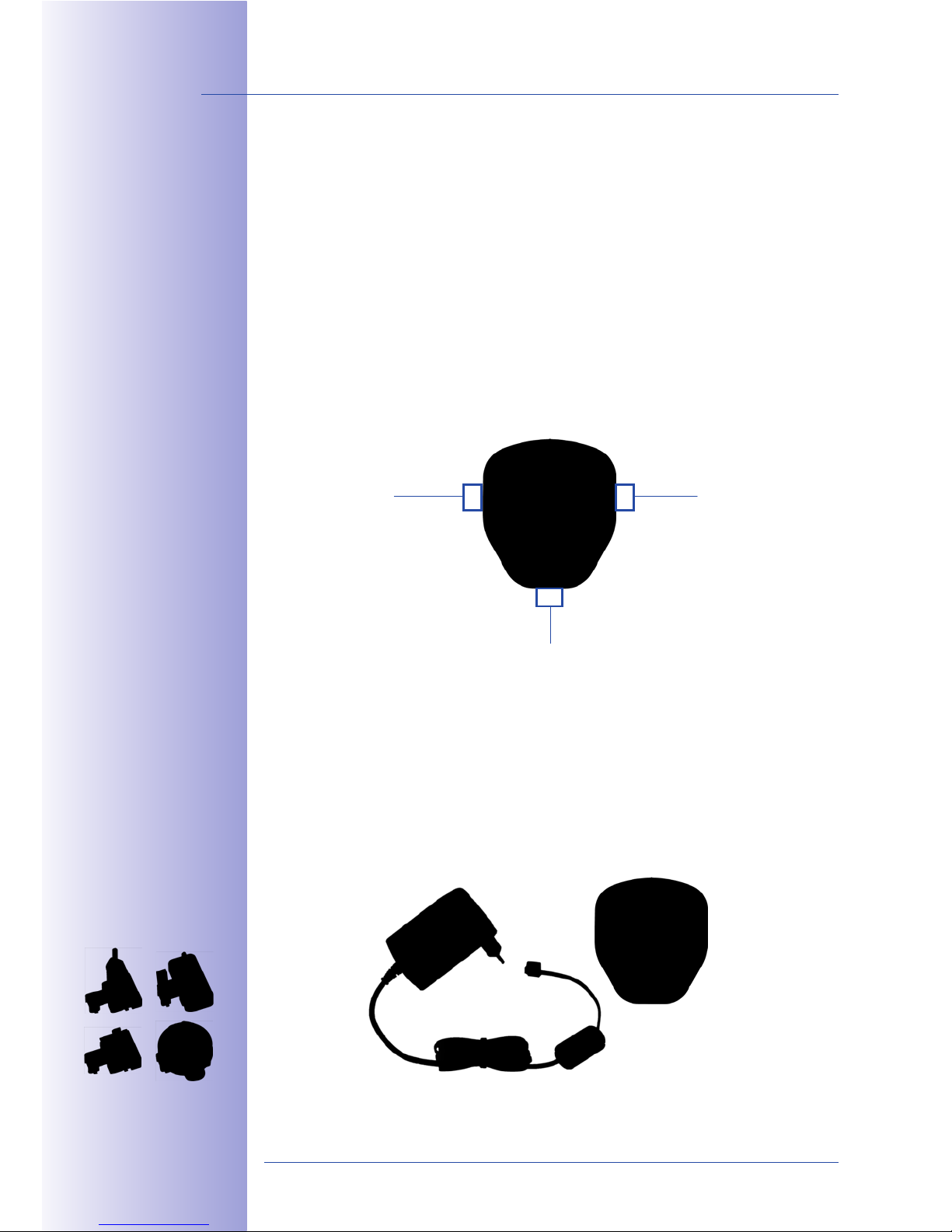
The MOBOTIX Network Power Adapter Set (NPA-PoE set) is a high-quality, robust, ultracompact, and - above all - multifunctional PoE injector with three connectors (network,
camera/PoE device, PC) and a universal power supply unit with adapter plugs. The Network
Power Adapter Set supplies the T24 door station and all other PoE devices with power in
accordance with the IEEE 802.3af standard. It is therefore possible to secure the power
supply for distances up to 100 m (300 ft) using the network cable. As a result, the T24 IP
Video Door Station can be supplied with PoE power via the adapter and connected directly
to a remote station (integrated crossover function).
This device is especially practical because the supplied power supply unit can be used
around the world by changing the adapters as required in just two simple steps. The “E.U.”
version of the NPA-PoE Set is supplied as standard with a European adapter, while the “INT”
version includes four adapters (EU, USA, UK, AUS). Another product benefit is the option to
connect to power sources from 12 V to 42 V that are independent of the network, which is
ideal for solar and battery operation of the door station (e.g., in a holiday home).
PoE injector
LAN or POWER
PC/VoIP
video telephone
or POWER
T24 door station (camera module)
RJ45
RJ45
RJ45
LAN/Power
PC/Power
Camera
Integrated and patented
crossover function
LAN/Power
PC/Power
Camera
!O?T[a?["`?D$+?`T
*'; !O?T[a?["`?D$+?
KT8 &'1<. *;*>+$# ("#
`bA bDA bh *'; abD
Page 49
49/148
Accessories
© MOBOTIX AG • Security-Vision-Systems • Made in Germany
www.mobotix.com • [email protected]
1.4.2 T24-OPT-IO (Extended Terminal Boards)
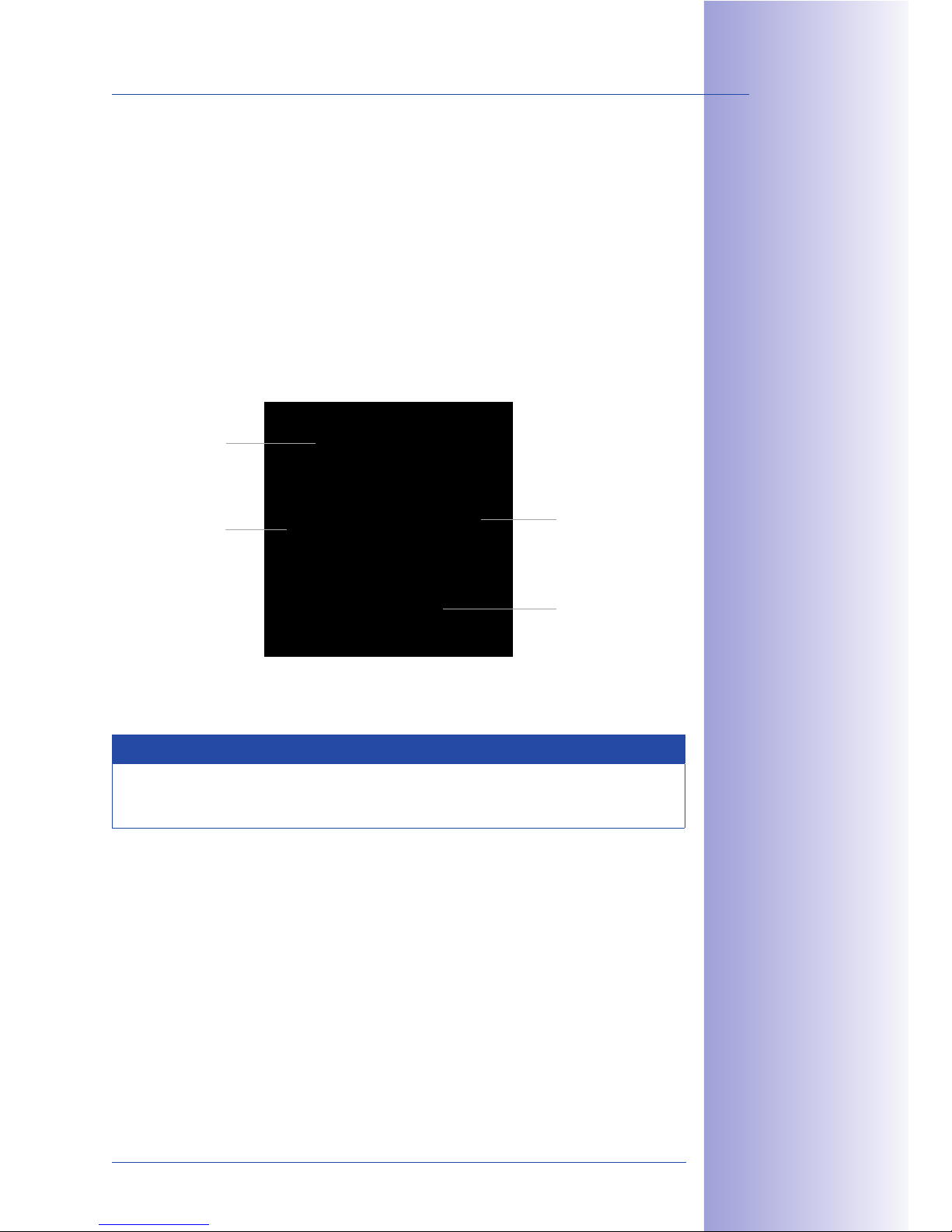
In addition to the ethernet terminal board (T24-OPT-ETH), MOBOTIX oers an IO module
(T24-OPT-IO) with extended connection options for the door station (e.g., doorbell buttons,
light, garage door opener, etc.).
The board provides 8 switch inputs and 3 switch outputs. The network cable and the camera
module T24-CamCore are connected in the same manner as the Ethernet terminal board.
Note
Please read further information on the connection details and on using this product
in Section 2.7.1.
89:?M[8?KM
Ethernet connector
with PoE supply
Cable sheath
contact
Camera connector
(RJ45)
Extended connector
Page 50
50/148
T24 System Manual Part 1: System Overview
© MOBOTIX AG • Security-Vision-Systems • Made in Germany
www.mobotix.com • [email protected]
1.4.3 Additional Devices For PoE Power Supply
By default, power is supplied to the T24 IP Video Door Station via the network cable that
is connected to the Ethernet terminal board behind the camera module. PoE injectors or
switches with integrated PoE power supply according to IEEE 802.3af can be used to
supply power to the network.
PoE+ According To IEEE 802.3at For Mx2wire+
If the T24 version with Mx2wire+ technology is installed, data and power are supplied to
the door station via a two-wire cable, which is connected to the network via an Mx2wire+
indoor unit. Due to the increased energy requirements of the Mx2wire+ technology, PoE
supply according to IEEE 802.3af is not sucient. A PoE injector/switch (performance
class PoE+ according to IEEE 802.3at) has to be used instead, or an external voltage
source (48 V DC) must be connected to one of the two Mx2wire+ units (info module
or indoor unit).
Switch Or PoE Injector?
A switch connects individual network-enabled devices to one another and delivers data.
In the case of a home network, this function is normally performed by an existing router
with multiple network ports, which is also capable of connecting to the Internet (such as
the Fritz!Box). In this case and if only one T24 door station needs to be supplied with power,
it is sucient to purchase one PoE injector.
When purchasing a switch with an additional PoE power supply, make sure that a sucient
number of ports are supported (this is especially important if other PoE-supplied devices
apart from the T24 are connected to the switch).
Furthermore, it is crucial that the switch fulfils all the requirements for using the PoE-supplied
door station outdoors (electromagnetic compatibility, lightning and surge protection through
galvanically-separated ports).
PoE switch
89:?K'("9-&#$U '("
)";3<$ -&+5 &';""# 3'&+
Page 51

51/148
Accessories
© MOBOTIX AG • Security-Vision-Systems • Made in Germany
www.mobotix.com • [email protected]
1.4.4 Additional Video Remote Stations
Thanks to the use of network technology, the T24 is not bound to just one expensive,
manufacturer-dependent remote station. It can be connected to any suitable VoIP video
phone (video: H.264, sound: G.711) in the world. In addition to supporting the two-way
video communication feature with video and sound, these devices support additional
features such as door/light control, image search, quick recording and PTZ functions. So
called SIP softphones are also suitable as remote video stations.
1.4.5 Door Sensors
Connection options are also provided on the door station for conventional door and door
lock switches (open/close door, open/close lock).
1.4.6 Electrical Door Opener
The T24 Door Station should always be connected to an electrical door locking system,
which can be activated via the T24-DoorMaster in a tamper-proof manner.
Product Information: Self-Locking Door Lock
Traditional door openers only electromechanically release a locking tab on the door. In
order to open an additional, key-locked door without using the key and as described
above, a door lock that can be locked/unlocked electrically is required instead of a
traditional door opener (e.g., Mediator, www.assaabloy.de).
This also applies when the door in question has to be locked at all times for insurance reasons
and the keyless door opening function of the T24 is to be used as well (transponder/PIN).
Page 52
52/148
T24 System Manual Part 1: Installation
© MOBOTIX AG • Security-Vision-Systems • Made in Germany
www.mobotix.com • [email protected]
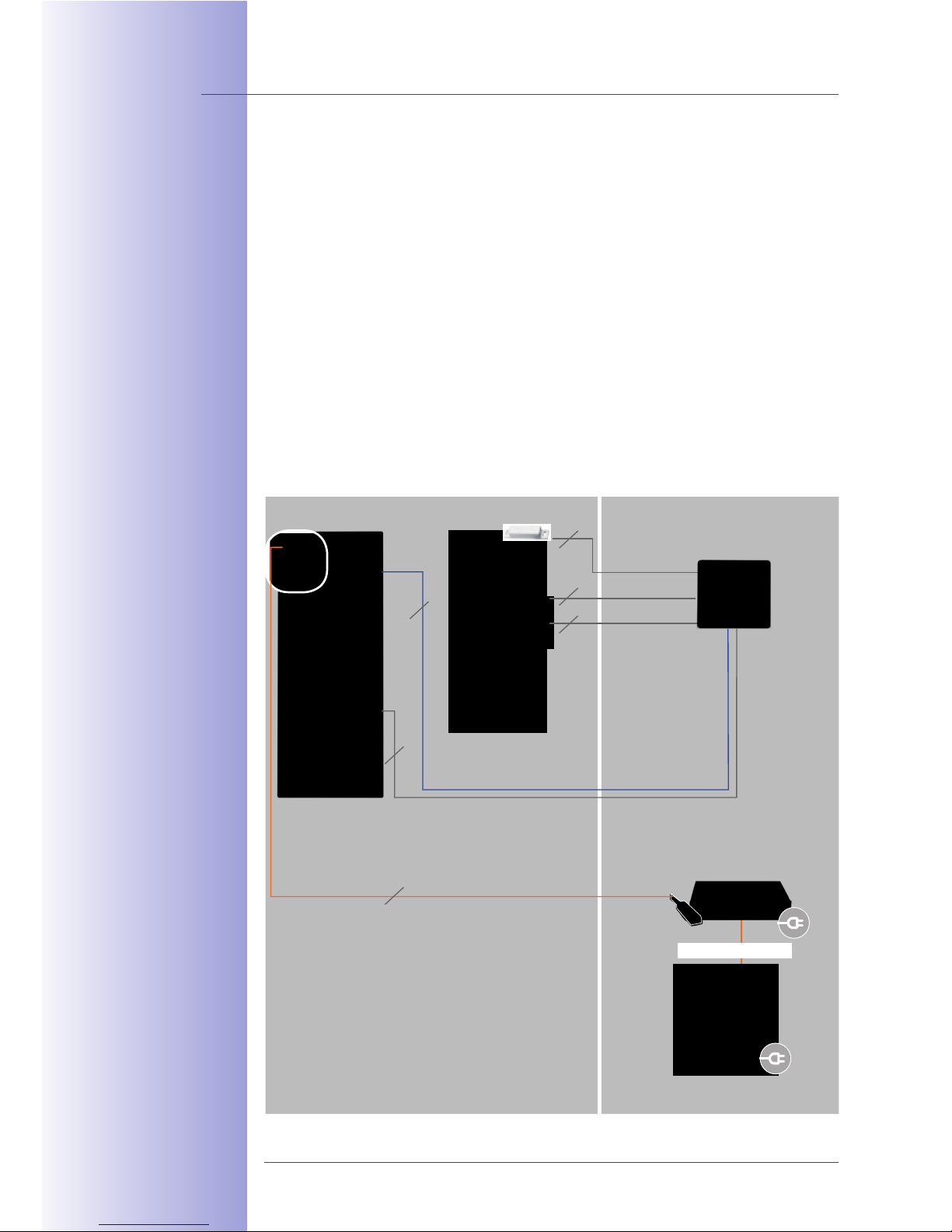
2 INSTALLATION
2.1 Overview: Connection And Wiring Diagrams
The following diagrams are an overview of the wiring plans that will allow you to connect
the T24 IP Video Door Station as intended. Please refer closely to the configuration that
best suits your particular needs.
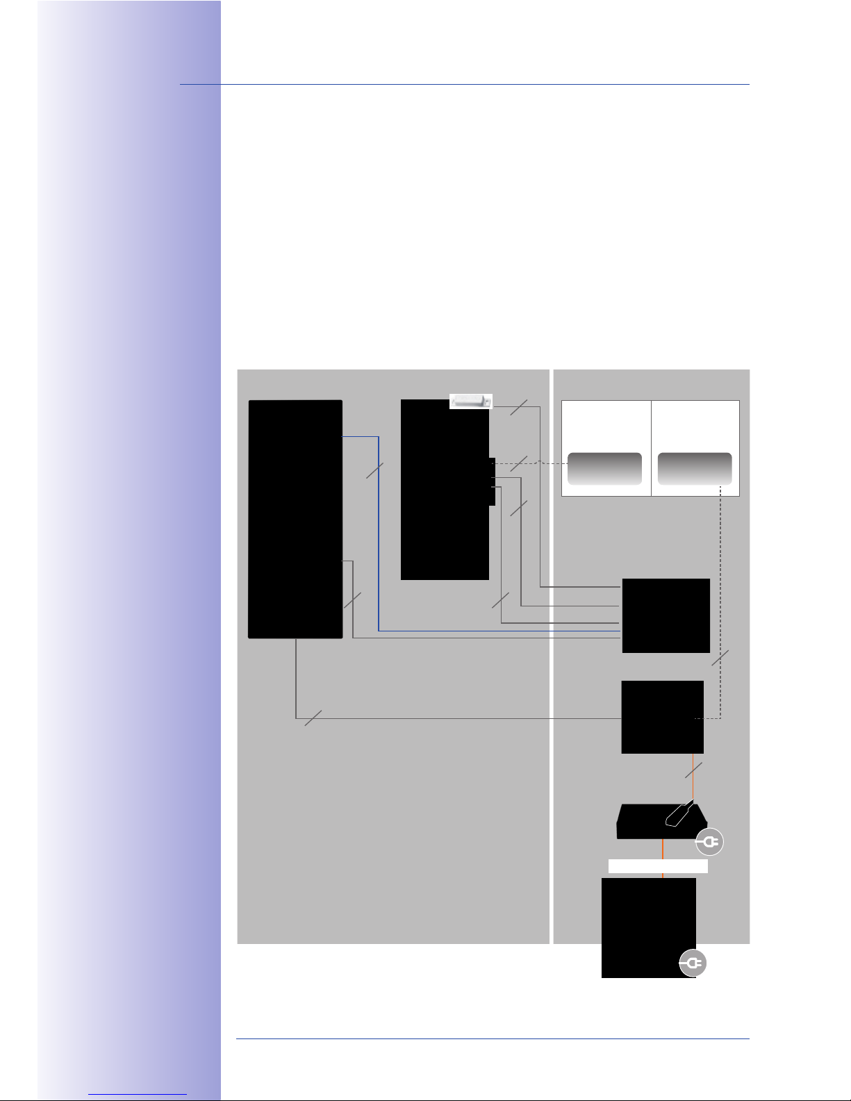
2.1.1 With A T24-DoorMaster
Using a T24-DoorMaster with decentralized access code memory makes it impossible
to open the door by bypassing the connection cable, thereby protecting your system
against unauthorized access. A battery, kept fully charged via MxBus at all times, supplies
power to the electric door opening mechanism - even in the case of a power failure.
85$ ]@3#$ */"7$
+5$ 1"''$1+&"'
2$1+&"'2 #$>#$2$'+2
+5$ '3)/$# "(
1*/<$ - #$2
N<*16, iD8i G.F
P#$1"))$';$;Q
"# G.J ))
M#*'@$, `+5$#'$+
\*+. c "# 5&@5$#
Outdoors Indoors
Door station
Door
T24-DoorMaster
Door Contact
Door Lock Switch
Door Opener
Anti-Theft Protection
Ethernet
MxBus
VoIP videophone
2
2
2
2
2
PoE switch
8
Page 53
53/148
Overview: Connection And Wiring Diagrams
© MOBOTIX AG • Security-Vision-Systems • Made in Germany
www.mobotix.com • [email protected]
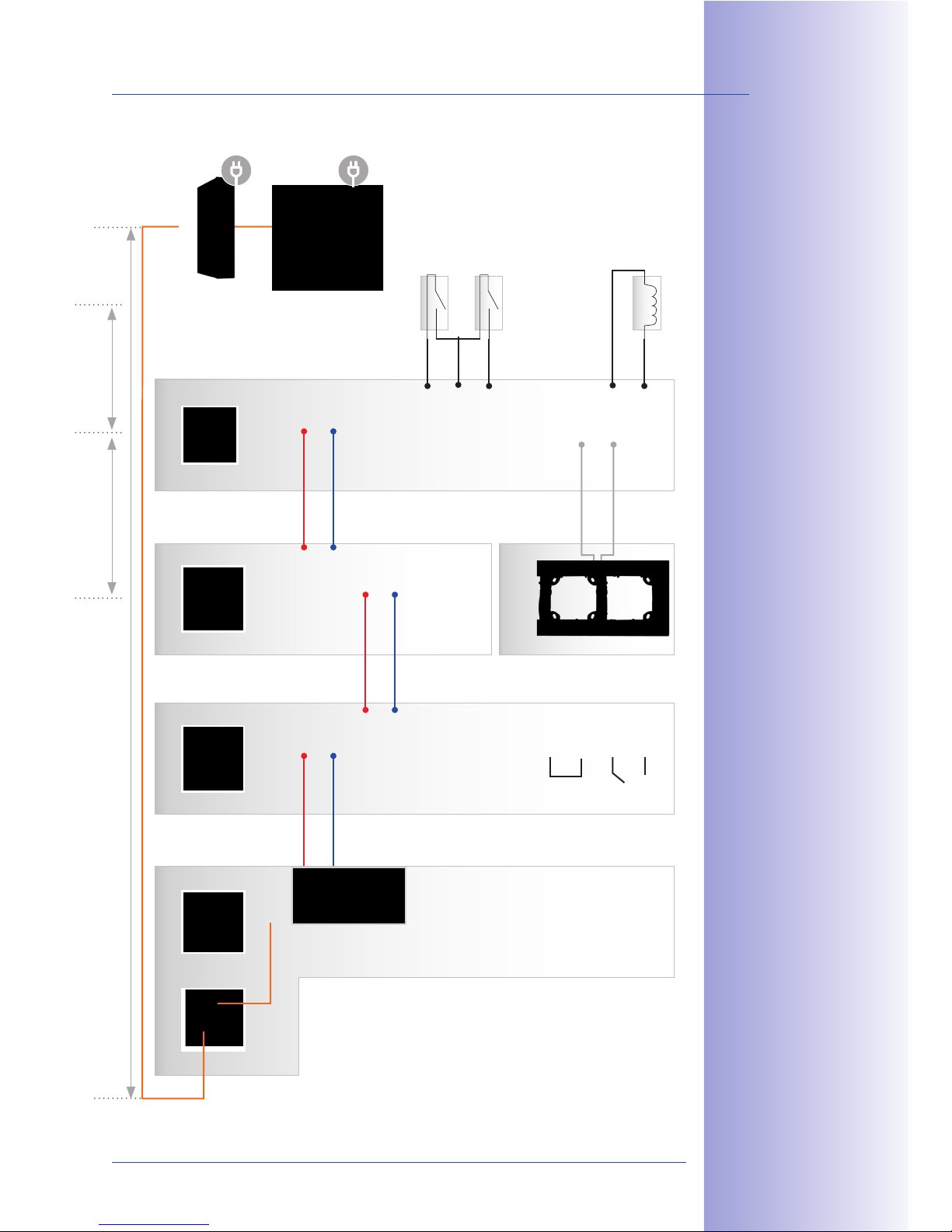
85$ 89:?C""#!*2+$# &2
*<-*42 1"''$1+$; +" *
(#$$ !0N32 1"''$1+"#
"( +5$ "3+;""# 2+*+&"'
P"' +5$ 1*)$#* )";3<$A
6$4>*; "# '(" )";3<$Q
!";3<$2 *#$ 1"''$1+$;
7&* +5$ <"">$;?+5#"3@5A
+-"?-&#$ !0N32 1*/<$
+5*+ +#*'2($#2 ;*+* *';
>"-$# 2&)3<+*'$"32<4
85$ )";3<$ +$#)&'*<
;$2&@'*+&"'2 *#$
*<2" <"1*+$; ;&#$1+<4
"' +5$ )";3<$
T24-CamCore T24-KeypadRFID T24-Info
T24-DoorMaster
MxETH
MX +
MX -
MX +
MX -
MX +
MX -
MX +
MX -
IN 1+
IN 1-
IN 2+
IN 2-
COM
COM
OUT A
OUT B
MX +
MX -
MX +
MX -
MX +
MX -
IN 1+
IN -
IN 2+
OUT 1+
OUT -
OUT 2+
T24-OPT-ETH
Door contact
Door lock switch
Door opener
(self-powered)
max. 100 m
max. 50 m max. 50 m
Connection of external devices (light relay, etc.)
and 12 V power supply unit
VoIP videophone
e.g. PoE switch
Anti-theft protection
(module frame)
Page 54
54/148
T24 System Manual Part 1: Installation
© MOBOTIX AG • Security-Vision-Systems • Made in Germany
www.mobotix.com • [email protected]
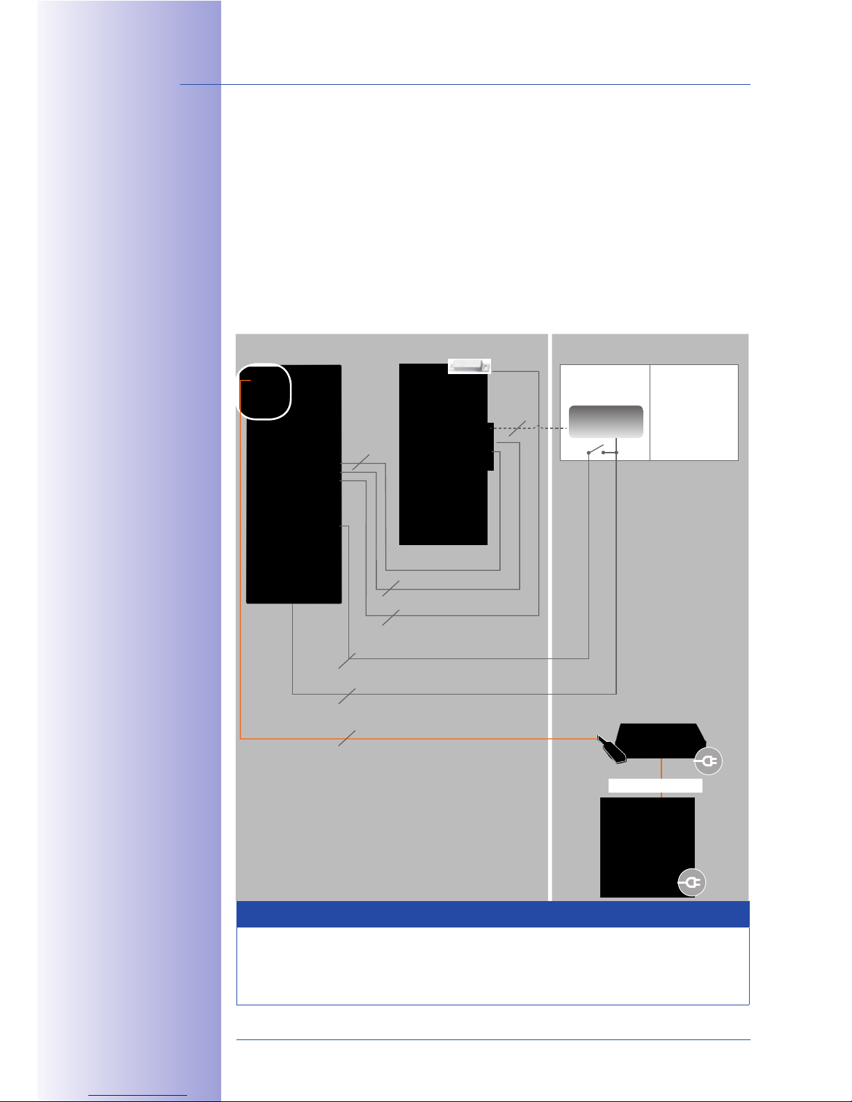
2.1.2 Without A T24-DoorMaster
When a T24-DoorMaster is not used, the electric door opener or Mediator, including
the door and door lock sensors, are connected directly to the keypad. In addition, an
external 12 V voltage is applied to the door mechanism/Mediator and bridged over
to the keypad.
The two cables for the electromagnetic anti-theft protection integrated into the T24 frame
(otherwise connected to and powered by the T24-DoorMaster) should be conducted inside
the building so that they can be connected to a 12 V supply in case modules are exchanged
later on.
Note
The anti-theft protection is connected to the DC power supply of the door opener via a
switch (switch on -> current is flowing -> protection deactivated). If the door opener works
with an AC power supply, the anti-theft protection requires its own DC voltage source.
85$ ]@3#$ */"7$ +5$
1"''$1+&"' 2$1+&"'2
#$>#$2$'+2 +5$ '3)/$#
"( 1*/<$ - #$2
N<*16, iD8i G.F
P#$1"))$';$;Q
"# G.J ))
M#*'@$, `+5$#'$+
\*+. c "# 5&@5$#
85$ $0+$#'*< E9 ^
23>><4 1*' /$ /#&;@$;
"7$# (#") +5$ !$;&*+"#
+" +5$ 6$4>*; +"
*7"&; 5*7 '@ +" 32$
*' *;;&+&"'*< E9 ^
1*/<$ +" +5$ 6$4>*;
Outdoors Indoors
Door Station
Switch box
Door
6–12 V DC
Power supply
VoIP video phone
2
PoE switch
Door contact
Anti-theft protection
12 V for electrical door opener
Ethernet
Door lock switch
Door opener
2
2
2
2
2
S
Switch (S)
for anti-theft
protection
(not included
in set)
8
Page 55
55/148
Overview: Connection And Wiring Diagrams
© MOBOTIX AG • Security-Vision-Systems • Made in Germany
www.mobotix.com • [email protected]
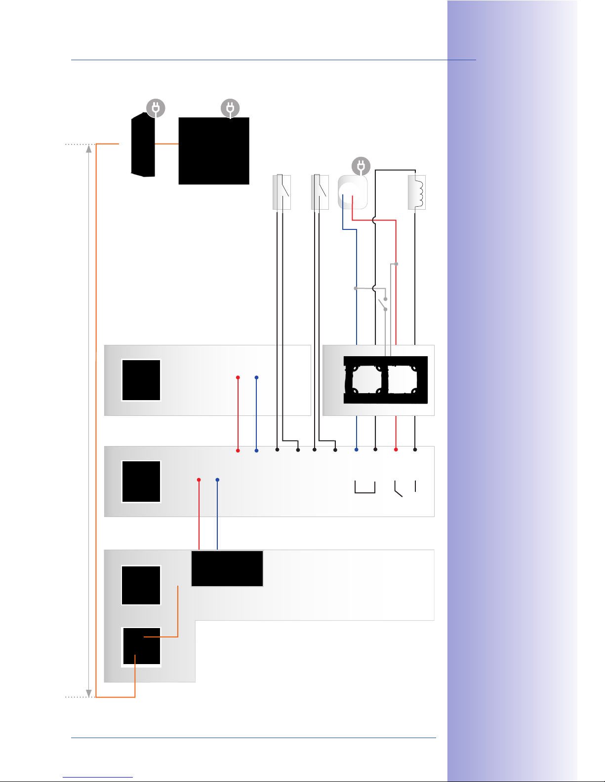
!";3<$2 *#$ 1"''$1+$;
7&* +5$ <"">$;?+5#"3@5A
+-"?-&#$ !0N32
1*/<$ +5*+ +#*'2($#2
;*+* *'; >"-$#
2&)3<+*'$"32<4 P1*/<$
'1<3;$; &' >*16*@ '@Q
85$ )";3<$ +$#)&'*<
;$2&@'*+&"'2 1*' /$ ("3';
;&#$1+<4 "' +5$ )";3<$
T24-CamCore T24-KeypadRFID T24-Info
MxETH
MX +
MX -
MX +
MX -
MX +
MX -
MX +
MX -
IN 1+
IN 1-
IN 2+
IN 2-
COM
COM
OUT A
OUT B
MX +
MX -
MX +
MX -
T24-OPT-ETH
Door contact
Door lock switch
Power supply
Door opener
max. 100 m
Connection of external devices (light relay,
etc.) and 12 V power supply unit
VoIP videophone
e.g. PoE switch
12 V DC
- +
Anti-theft protection
(module frame)
S
Page 56
56/148
T24 System Manual Part 1: Installation
© MOBOTIX AG • Security-Vision-Systems • Made in Germany
www.mobotix.com • [email protected]
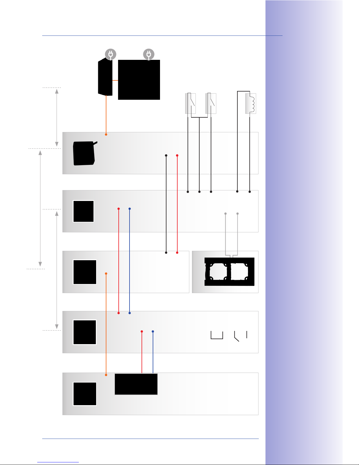
2.1.3 With T24-Info2wire+ And T24-DoorMaster
To be able to use a bell wire already laid in the building to connect the T24 door station
to the network and supply it with power, the T24 version with Mx2wire+ technology is
required. The two-wire cable must be conducted from the door station info module to
a second Mx2wire+ unit inside the building, to which data and power is supplied, for
example, via a PoE+ switch.
Installing a T24-DoorMaster with decentralized access code memory makes it impossible
to open the door by bypassing the connection cable, and therefore protects against
unauthorized access. A battery, kept fully charged via MxBus at all times, supplies power
to the electric door opening mechanism (even in the case of a power failure).
85$ ]@3#$ */"7$ +5$
1"''$1+&"' 2$1+&"'2
#$>#$2$'+2 +5$ '3)/$#
"( 1*/<$ - #$2
N<*16, iD8i G.F
P#$1"))$';$;Q
"# G.J ))
M#*'@$, `+5$#'$+
\*+. c "# 5&@5$#
85$ $0+$#'*< E9 ^ >"-$#
23>><4 &'1<3;&'@ * 1*/<$
(#") +5$ 2-&+15 /"0 &2
#$V3&#$; 5$#$ ("# *'
P">+&"'*<Q !$;&*+"#
Outdoors Indoors
Door station
Switch box
Door
T24-Info2wire+
indoor unit
T24-DoorMaster
12 V DC
(for Mediator)
Power supply
Door contact
Door lock switch
Door opener
Anti-theft protection
Data and power over two-wire connection
MxBus
48-57 V DC
(alternative)
Power supply
VoIP videophone
2
2
2
2
2
2
2
2
PoE+ switch
8
Page 57
57/148
Overview: Connection And Wiring Diagrams
© MOBOTIX AG • Security-Vision-Systems • Made in Germany
www.mobotix.com • [email protected]
!";3<$2 *#$ 1"''$1+$;
7&* +5$ <"">$;?+5#"3@5A
+-"?-&#$ !0N32
1*/<$ +5*+ +#*'2($#2
;*+* *'; >"-$#
2&)3<+*'$"32<4 P1*/<$
'1<3;$; &' >*16*@ '@Q
a' `+5$#'$+ >*+15
1*/<$ &2 32$; +" 1"''$1+
+5$ !09-&#$U &'("
)";3<$ +" +5$ 1*)$#*
85$ )";3<$ +$#)&'*<
;$2&@'*+&"'2 *#$
*<2" <"1*+$; ;&#$1+<4
"' +5$ )";3<$
85$ 89:?C""#!*2+$# &2
*<-*42 1"''$1+$; +" *
(#$$ !0N32 1"''$1+"#
"( +5$ "3+;""# 2+*+&"'
P"' +5$ 1*)$#* )";3<$A
6$4>*; "# '(" )";3<$Q
T24-CamCore T24-KeypadRFID
MxETH
MX +
MX -
MX +
MX -
MX +
MX -
MX +
MX -
IN 1+
IN 1-
IN 2+
IN 2-
COM
COM
OUT A
OUT B
Door contact
Door lock switch
Door opener
(self-powered)
e.g. PoE+ switch
T24-Info2wire+
Anti-theft protection
(module frame)
MxETH
48 V +
48 V -
Data A
Data B
max. 50 m
Cable length depends on the two-wire cable used
(up to 500 m)
T24-DoorMaster
MX +
MX -
IN 1+
IN -
IN 2+
OUT 1+
OUT -
OUT 2+
T24-Info2wire+
RJ45
48 V +
48 V -
Data A
Data B
max. 10 m
Connection of external devices (light relay,
etc.) and 12 V power supply unit
normally a short
patch cable
VoIP videophone
Page 58
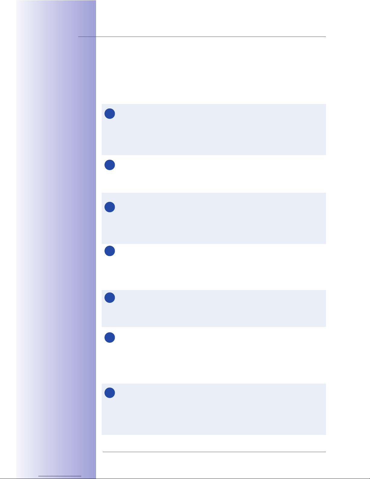
58/148
T24 System Manual Part 1: Installation
© MOBOTIX AG • Security-Vision-Systems • Made in Germany
www.mobotix.com • [email protected]
2.1.4 Recommendation For Cabling
Depending on the model, the door station and its remote stations require one of the
following cabling configurations. Please take note of our cabling recommendations and
the maximum cable lengths. Both the network cable and other cables must be stripped
at the door station ends.
Network cable from the Ethernet terminal board behind the camera module
to the switch/injector
• Recommendation: Category 5 (Cat 5) Ethernet installation cable or higher; Cat
7 cable is designed for 10 Gbit Ethernet (max. future compatibility)
• Max. cable length: 100 m
Two wires from the door station to the T24-DoorMaster for the MxBus connector
• Recommendation: YSTY (telephone) solid wire, core diameter 0.6 to 0.8 mm
• Max. cable length: 50 m
Cables from the T24-DoorMaster to the electric door opener, the door contact
and the door lock switch
• Recommendation: YSTY (telephone) solid wire, core diameter 0.6 to 0.8 mm
• Max. cable length: depending on the manufacturer, max. 50 m
Two wires from the T24-DoorMaster to an additional power supply (for
example, 12 V for Mediator operation)
• Recommendation: YSTY (telephone) solid wire, core diameter 0.6 to 0.8 mm
• Max. cable length: depending on the manufacturer
Two wires from the keypad to the 230 V light relay (if present)
• Recommendation: YSTY (telephone) solid wire, core diameter 0.6 to 0.8 mm
• Max. cable length: depending on the manufacturer
Two-wire cable from the T24-Info2wire+ info module to the indoor unit (as
an alternative to the outdoor station being directly connected to the network)
• Recommendation: existing, previously laid bell wire (core diameter 0.6 to
0.8 mm)
• Max. cable length: 200 m (JY, A2Y, YR), 300 m (NY), 500 m (Cat 7)
Two wires from the door station to the T24-DoorMaster for connecting the
MOBOTIX anti-theft protection (for unlocking when exchanging modules)
• Recommendation: black two-wire cable already fitted to the frame, possibly
extended with YSTY (telephone) solid wire, core diameter 0.6 to 0.8 mm
• Max. cable length: 50 m
85$ 23>>< $; >*+15 1*/<$
&2 32$; +" 1"''$1+ +5$
89:?K'("9-&#$U '("
)";3<$ +" +5$ 1*)$#*
Ti, &'2+*<<*+&"'
1*/<$ P'"+ <&7$Q
85$ )*0&)3)
1"']@3#*+&"' &2 2>$1&]$;
("# +5$2$ 1*/<&'@
#$1"))$';*+&"'2
4
5
6
7
3
2
1
Page 59
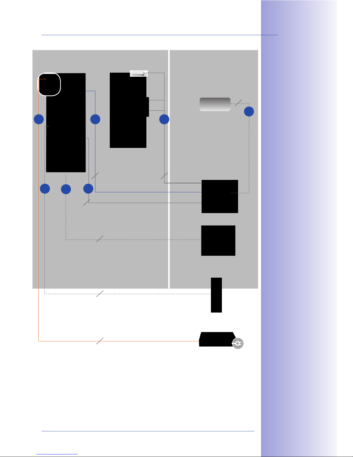
59/148
Overview: Connection And Wiring Diagrams
© MOBOTIX AG • Security-Vision-Systems • Made in Germany
www.mobotix.com • [email protected]
\*/<$ J )*4 /$
32$; &'2+$*; "(
1*/<$ E P*<+$#'*+&7$
1"''$1+&"' ">+&"'Q
Door station
Door
T24-DoorMaster
PoE switch
(remote station connection)
12 V DC
(for Mediator)
Power supply
4
Power relay
(e.g., for lamp)
5 7
3
2
2
2
2
8
6
2
Cat 5 installation cable or higher
Max. length: 100 m
YSTY 0.8 mm (MxBus) – max. length: 50 m
YSTY 0.8 mm (anti-theft protection) –
max. length: 50 m
Two-wire (alternative network connection)
Max. length: 500 m
YSTY 0.8 mm (e.g., external light)
Max. length: depends on the manufacturer
YSTY 0.8 mm (door opener,
door contact and door lock switch –
max. length: 50 m
YSTY 0.8 mm (Mediator operation)
Max. length: depends on the manufacturer
T24-Info2wire+
indoor unit
21
6
Page 60
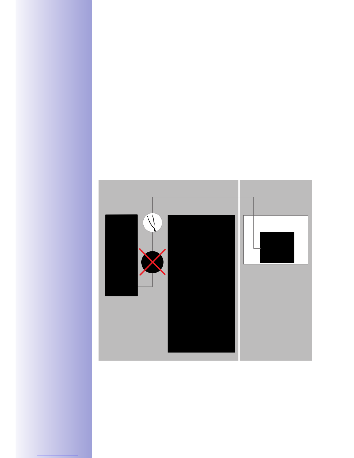
60/148
T24 System Manual Part 1: Installation
© MOBOTIX AG • Security-Vision-Systems • Made in Germany
www.mobotix.com • [email protected]
2.1.5 Installation Tip: Replacing An Existing Doorbell With The T24
The MOBOTIX T24 IP Video Door Station, in particular the version with integrated Mx2wire+
technology (for network connection with simultaneous power supply via the same two-wire
cable), is an ideal retrofit solution that is very easy and quick to install.
The following two installation steps are normally all that is required to replace an existing,
simple doorbell with a complete T24 set including a T24-DoorMaster:
Step 1: Connect The T24 Via The Two-Wire Cable
Unscrew and remove the doorbell. Connect the wire pair to the T24-Info2wire+ info module
(T24 is mounted directly above the cable). This wire pair is conducted directly to the electrical
cabinet, from where it is connected to the power supply and remote stations via the
T24-Info2wire+ indoor unit.
Door
Existing two-wire cable
Electrical cabinet
T24-Info2wire+
indoor unit
Door station with
T24-Info2wire+
Outdoors Indoors
Page 61
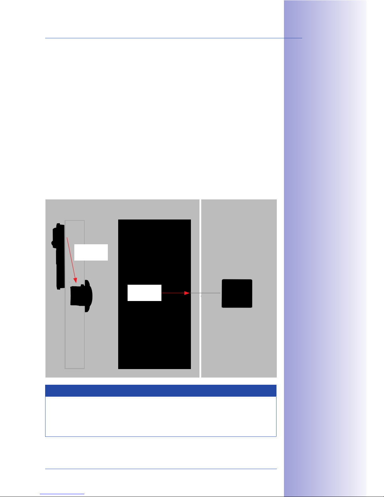
61/148
Overview: Connection And Wiring Diagrams
© MOBOTIX AG • Security-Vision-Systems • Made in Germany
www.mobotix.com • [email protected]
Step 2: Install And Connect The T24-DoorMaster
Install the T24-DoorMaster in a in-wall socket on the wall behind the door station (inside
the building). Besides the in-wall socket, only two holes are required for the entire cabling.
Hole A
Use a long drill bit to drill a hole from the door station downwards at an angle,
through the brickwork to the in-wall socket of the T24-DoorMaster on the interior
wall surface. Insert a 4-wire cable for MxBus and the anti-theft protection (see Section
2.1.4, Recommendation For Cabling).
Hole B
Use a shorter drill bit to drill a hole through the brickwork from the door lock/
door opener to the in-wall socket of the T24-DoorMaster. Feed the connectors for the
door opener, door contact and door lock switch through this hole (see Section 2.5, Installing
The T24-DoorMaster).
Note
Please contact a specialist (e.g. a locksmith) for the installation and selection of
any components that may be required (door opener, magnetic sensors). Door
openers and door contacts are available as accessories from other suppliers (e.g.
www.assaabloy.com).
Door
T24-DoorMaster
Hole B
Hole A
Wall
Indoors
Page 62
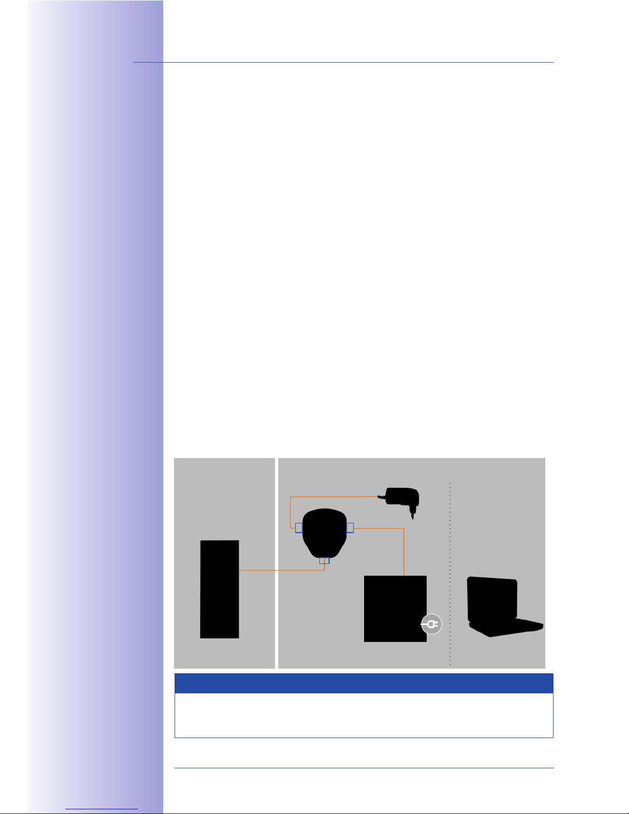
62/148
T24 System Manual Part 1: Installation
© MOBOTIX AG • Security-Vision-Systems • Made in Germany
www.mobotix.com • [email protected]
2.2 Remote Stations And Network Connection
2.2.1 Notes On Cable Lengths And Power Supply
The T24 door station can only be powered using the Ethernet port of the door camera.
A MOBOTIX PoE adapter (MX-NPA-PoE) or other similar, high-quality PoE product
conforming to IEEE 802.3af is required to supply the T24 with power (PoE switch). A PoE+
switch (IEEE 802.3at) or a 48 V power supply unit can be used to supply power to the T24
version with Mx2wire+ technology.
The maximum length of the network cable for power supply over an Ethernet cable
is 100 m.
Make sure that you only connect the door station or T24-Info2wire+ indoor unit to switches
or routers that support the 10/100 Mbps network interface. Check the LED activity of the
corresponding port at the switch or router.
2.2.2 Direct Connection Of One Remote Station
If the door station is to be connected for operation to one remote station only (computer
with MxEasy or VoIP videophone), MOBOTIX recommends using a MOBOTIX PoE adapter
(MX-NPA-PoE) to supply power to the door station. Connect the devices as shown in the
following connection diagram:
Connection With MOBOTIX PoE Adapter
Note
The Grandstream videophone has two ETH connectors, and it can alternatively be
connected wirelessly to a network using a WLAN stick (USB port).
Outdoors Indoors
VoIP video phone PCDoor station
PC/Power
LAN/Power
Camera
RJ45
RJ45
PoE adapter
(MX-NPA-PoE)
Power supply
85$ !MNM8KO ["`
*;*>+$# P!O?T[a?
["`?D`8Q ($*+3#$2
* 1#"22"7$# (3'1+&"'
("# ;&#$1+ 1")>3+$#
1"''$1+&"'A *'; 1*'
$&+5$# /$ 1"''$1+$;
+" +5$ )*&'2 23>><4
"# +" "+5$# 7"<+*@$
2"3#1$2 PE9e:9 ^Q
RJ45
Page 63
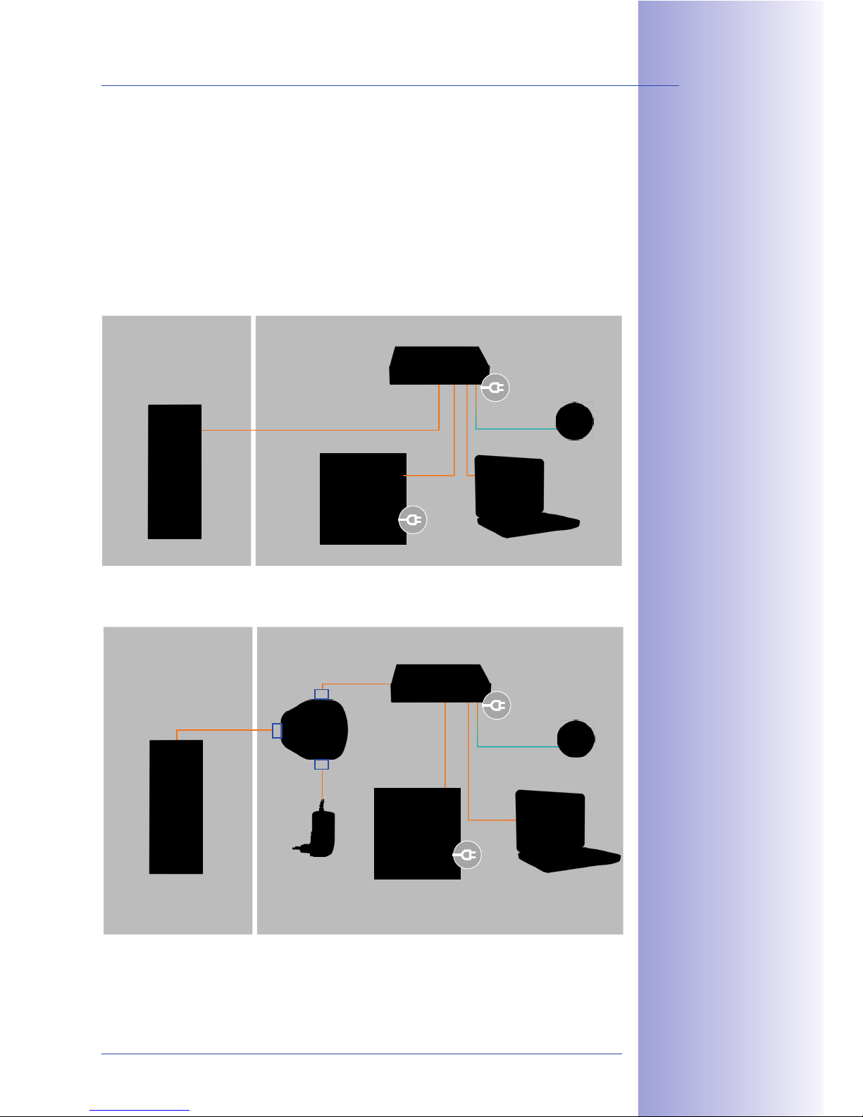
63/148
Remote Stations And Network Connection
© MOBOTIX AG • Security-Vision-Systems • Made in Germany
www.mobotix.com • [email protected]
2.2.3 Network Connection With Multiple Remote Stations
If the door station is to be connected for operation with multiple remote stations (computers
with MxEasy or VoIP videophones) in an existing network (for example, via an Internet box),
MOBOTIX again recommends using a MOBOTIX PoE adapter (MX-NPA-PoE) or a switch
with multiple ports to supply power to the door station. Connect the devices as shown in
the following connection diagram:
Connection With PoE Switch
Connection With MOBOTIX PoE Adapter
K( )3<+&><$ ["`?23>><&$;
$'; ;$7&1$2 P2315 *2
2$7$#*< K[ 1*)$#*2Q
*#$ +" /$ ">$#*+$;A
4"3 25"3<; 1"'2&;$#
32 '@ * ["` 2-&+15
Outdoors Indoors
VoIP video phone PCDoor station
PoE switch and router
LAN/Internet
Outdoors Indoors
VoIP video phone PCDoor station
Switch & Router
LAN/Internet
PC/Power
LAN/Power
Camera
RJ45
RJ45
RJ45
PoE adapter
(MX-NPA-PoE)
Power supply
85$ 89: P-&+5 *;;&+&"'*<
["` >"-$# 23>><4A ("#
$0*)><$A 32 '@ +5$
!MNM8KO ["` *;*>+$#Q
*'; &+2 #$)"+$ 2+*+&"'2
1*' *<2" /$ 1"''$1+$; +"
*' $0&2+ '@ SdaT #"3+$#
-&+5 &'+$@#*+$; 2-&+15
(3'1+&"' PCDd /"0Q
Page 64
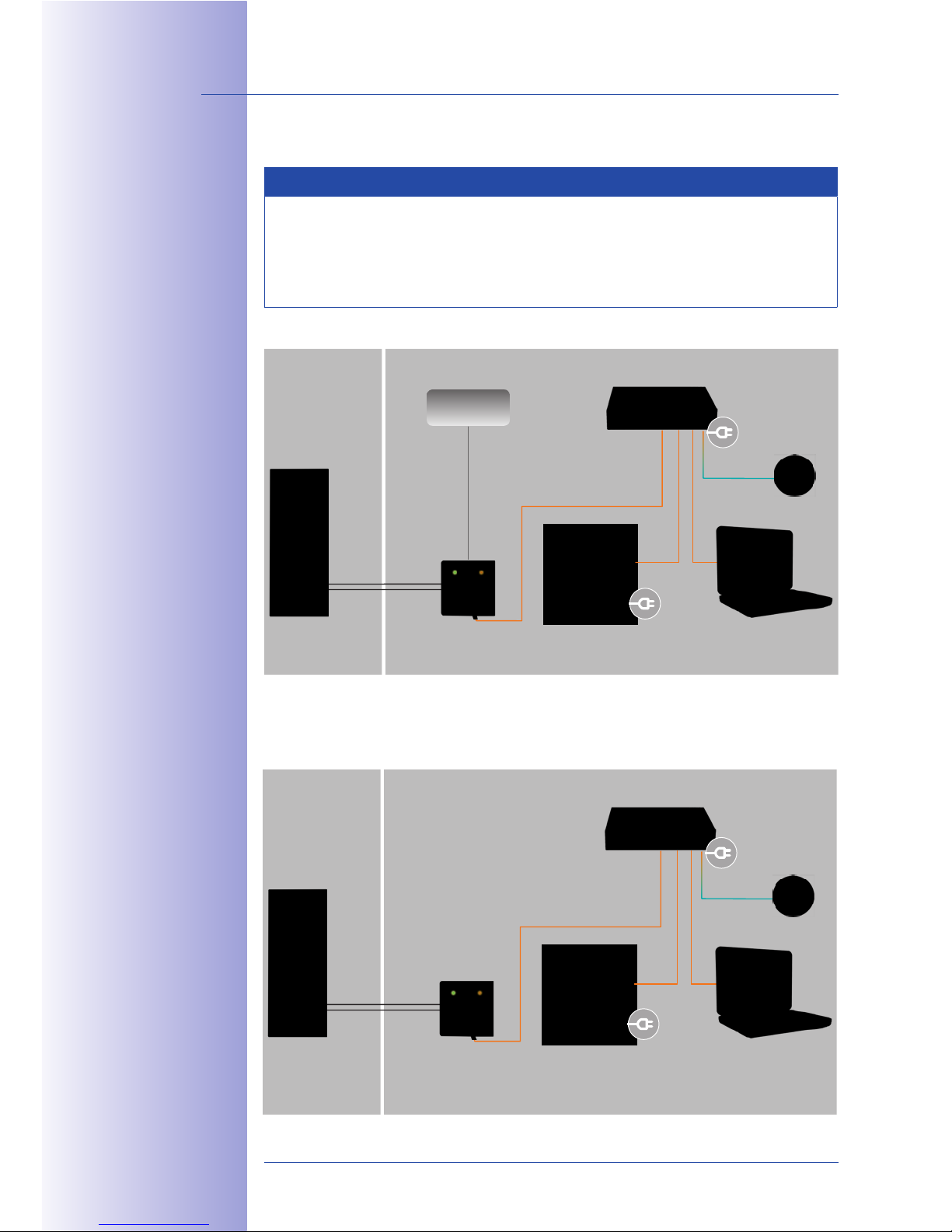
64/148
T24 System Manual Part 1: Installation
© MOBOTIX AG • Security-Vision-Systems • Made in Germany
www.mobotix.com • [email protected]
Connection With Mx2wire+ And Optional 48 V Power Supply
Note
For a door station with integrated Mx2wire+ technology, an external voltage
source (48 V DC) - connected via two wires directly to one of the two T24-Info2wire+
units (info module or indoor unit) - can also be used to supply power via the
network cable.
Connection With Mx2wire+ And PoE+ Switch
Outdoors Indoors
Two-wire cable
(Data & power)
VoIP video phone PCDoor station
Switch & Router
LAN/Internet
T24-Info2wire+
indoor unit
Power supply
48-57 V DC
a' $0&2+ '@ CDd /"0
1*' *<2" /$ 32$; +"
1"''$1+ +5$ 89:?
K'("9-&#$U &';""# 3'&+
&'2+$*; "( * 2-&+15
Outdoors
Indoors
Two-wire cable
(Data and power)
VoIP video phone PCDoor station
PoE+ Switch & Router
LAN/Internet
T24-Info2wire+
indoor unit
a<+5"3@5 * ["`U
2-&+15 1")>< $2 -&+5
+5$ K``` FG9.I*+
2+*';*#;A 32&'@ * :F ^
3'&+ +" 23>><4 >"-$#
&2 '"#)*<<4 +5$ )"#$
$1"'")&1*< ">+&"'
&( "'<4 "'$ $'; ;$7&1$
>"-$#$; 7&* ["`U
&2 +" /$ ">$#*+$;
Page 65
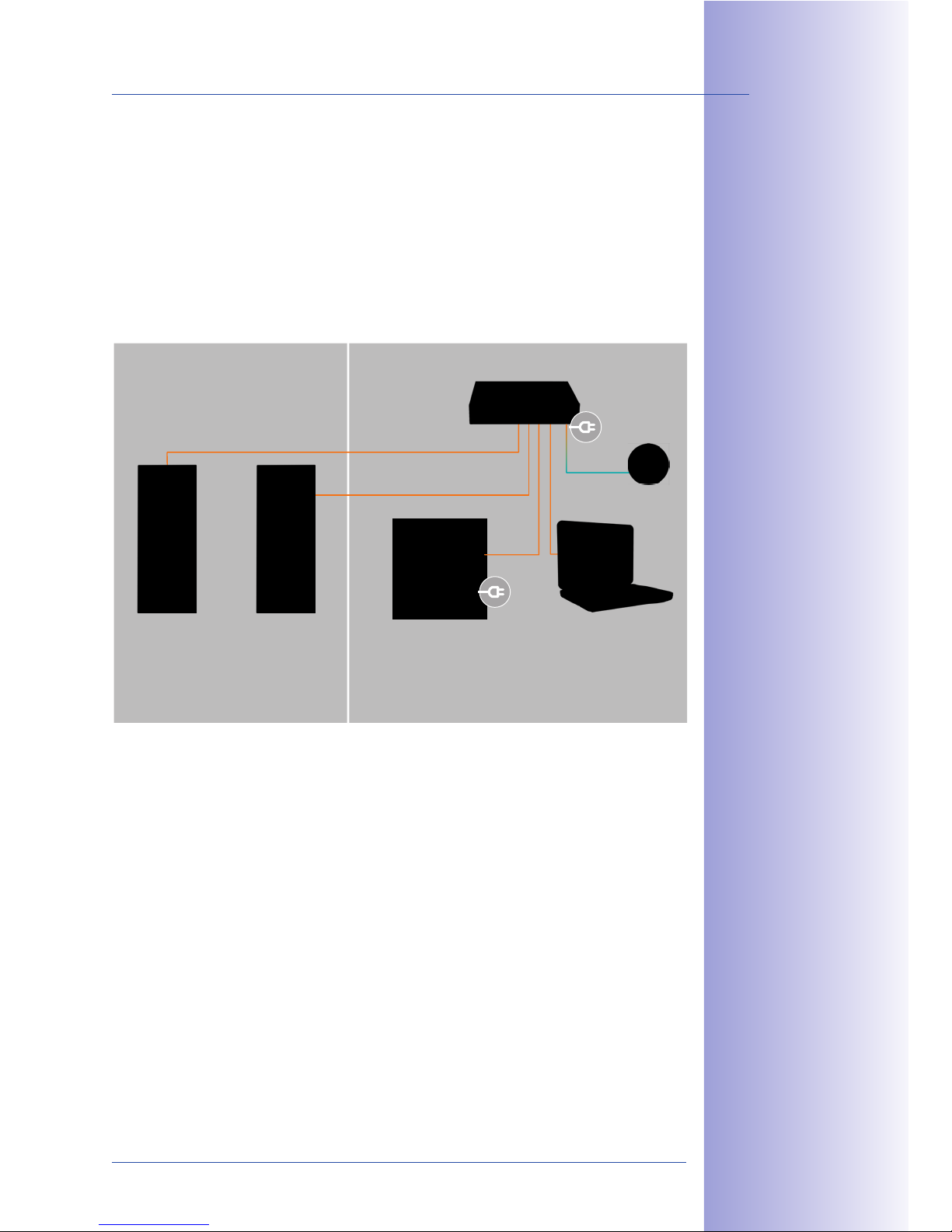
65/148
Remote Stations And Network Connection
© MOBOTIX AG • Security-Vision-Systems • Made in Germany
www.mobotix.com • [email protected]
Connecting Multiple T24 Door Stations
In general, a (PoE) switch can be used to connect several T24 door stations to the same
remote stations.
However, only one T24 can be connected to a T24-DoorMaster.
Each transponder card can be programmed in such a way that it can be used on all the
existing T24 door stations for opening the door.
Outdoors Indoors
VoIP video phone
(operation of door station A
and door station B)
PC
(operation of door station A
and door station B)
PoE switch and router
Door station A
(opens entrance A)
Door station B
(opens entrance B)
LAN/Internet
Page 66

66/148
T24 System Manual Part 1: Installation
© MOBOTIX AG • Security-Vision-Systems • Made in Germany
www.mobotix.com • [email protected]
2.3 Mounting The Frame And Housing
A complete T24 door station system includes components that are mounted next to the
entrance door, which means they are usually installed outdoors, as well as components
such as the T24-DoorMaster, remote stations and power supplies that are installed inside
a building.
Please note that only the T24 camera, keypad and info module are suitable for outdoor
installation (IP65, -30°C to +50°C/-22°F to +122°F). The modules will only be weatherproof
if they have been installed correctly using matching MOBOTIX housings and frames.
2.3.1 Determining The Installation Position
Before installing the door station, you need to decide exactly where to install it. In addition
to being mounted vertically (most popular installation option), the door station can also
be mounted horizontally.
In a vertical layout, the camera module T24-CamCore is normally positioned right at the
top. The keypad is located directly underneath, followed by the info module.
Note
Position the housing directly above the cables that come out of the wall (network,
two-wire cables). None of the connection cables should remain visible, as this would
make them vulnerable to manipulation.
B '+,
8" 1*>+3#$ @"";?V3*<&+4
&)*@$2 *+ '&@5+ *2 -$<<A
]+ *' "3+;""# <&@5+
*>>#"0&)*+$<4 E ) */"7$
+5$ ;""# 2+*+&"' P-&+5
&'+$@#*+$; )"+&"' 2$'2"#Q
Horizontal installationVertical installation
Page 67
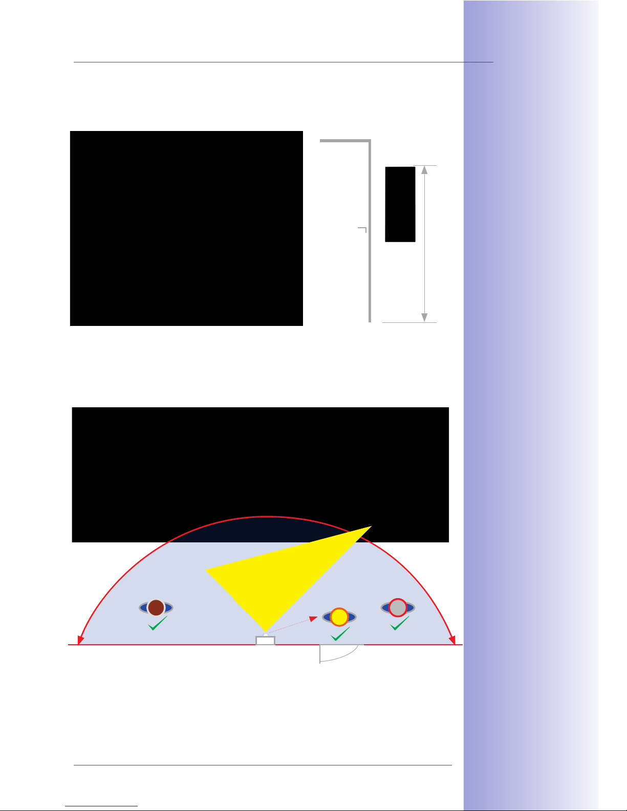
67/148
Mounting The Frame And Housing
© MOBOTIX AG • Security-Vision-Systems • Made in Germany
www.mobotix.com • [email protected]
To ensure ease of use, the system should be installed to accommodate people of dierent
heights. The height from the ground to the upper edge of the frame should be at least 1.60 m.
Unlike conventional door cameras, the T24 CamCore with its 180° image angle is also
able to record visitors when they are NOT standing directly in front of the lens. This means
that the door station can be mounted quite flexibly, which is particularly useful with
wide doors.
The installation can be on-wall, in-wall or using a cavity socket. MOBOTIX provides two
dierent types of housing for these installation methods. The modules and the frame fitted
to the housing are suitable for all installation options.
1.60 m
Door station
(located next to the door)
Standard 90°
Door
HD Super 180° Panorama
Original MOBOTIX T24 Image: 1280x 480
Page 68
68/148
T24 System Manual Part 1: Installation
© MOBOTIX AG • Security-Vision-Systems • Made in Germany
www.mobotix.com • [email protected]
2.3.2 Inserting All The Cables
On-Wall Housing
The housing has cable guides made of elastic rubber to ensure the cable entry points
are waterproof.
Use only one cable guide for each cable. Pierce the cable guide you require using a
screwdriver or other similar tool and feed the cable into the housing. If the cable is multiwire, separate the individual wires once the cable is in the housing.
In-Wall And Cavity Housing
Remove the insert and use a screwdriver or similar tool to pierce
through all the openings on the rear or on sides required for
inserting cables. As the housing is embedded in the brickwork,
this usually makes for a tight seal. If in doubt, or when using a
cavity housing, you should additionally seal the cable guides
with silicone.
B '+,
C" '"+ ">$' +5$ 1*/<$
@3&;$2 3> +"" -&;$ P("#
$0*)><$A &( 4"3 *#$ 32&'@
* 13++$#QA *2 1*/<$2 ($;
&'2&;$ +5$ 5"32&'@ )32+
/$ +&@5+<4 $'1<"2$; P+"
$'23#$ * +&@5+ 2$*<Q
Pierce required guide holes, e.g.
with screw driver
Guide cable through hole
(one cable per inlet)
85$ '2$#+ >#$7$'+2
+5$ &'?-*<< 5"32&'@
(#") @$++&'@ ; #+4 *';
/$ '@ ;$("#)$; ;3# '@
&'2+*<<*+&"' &' * -*<<j &+
)32+ /$ #$)"7$; *';
+5$' >"2&+&"'$; *@* '
-5$' >#$>*#&'@ +5$ 1*/<$2
Pierce required
guide holes
Page 69
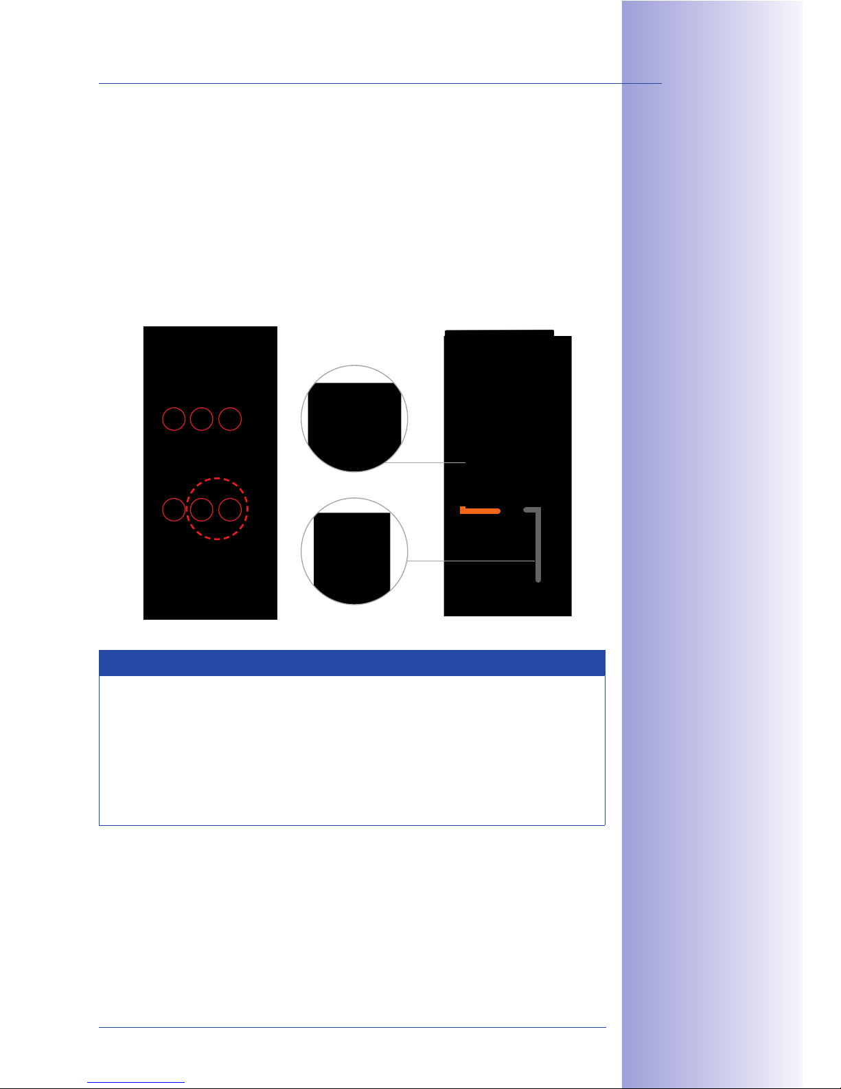
69/148
Mounting The Frame And Housing
© MOBOTIX AG • Security-Vision-Systems • Made in Germany
www.mobotix.com • [email protected]
Important: Pay Attention To The Position Of The Cables
When installing the door station, make sure that all the required cables (network, MxBus,
anti-theft protection and so on) are laid in such a way that they protrude from the wall
directly below the housing openings provided.
This particularly applies to the on-wall housing that has up to six cable guides (triple frame).
Only one cable (multi-wire cables may be used) should be inserted into each cable guide.
The cables should be long enough so that sucient cable reserves remain to allow easy
cabling within the housing (see Section 2.3.4).
Notes
• Position the housing in the center above the cables
• Only use one cable in each cable guide
• Make sure sucient cable reserves are provided
• Hint: If longer cable reserves are required, you can mount an additional
in-wall socket underneath the on-wall housing (see the dashed line in the
figure above).
Network cable
MxBus, anti-theft protection, etc.
Page 70
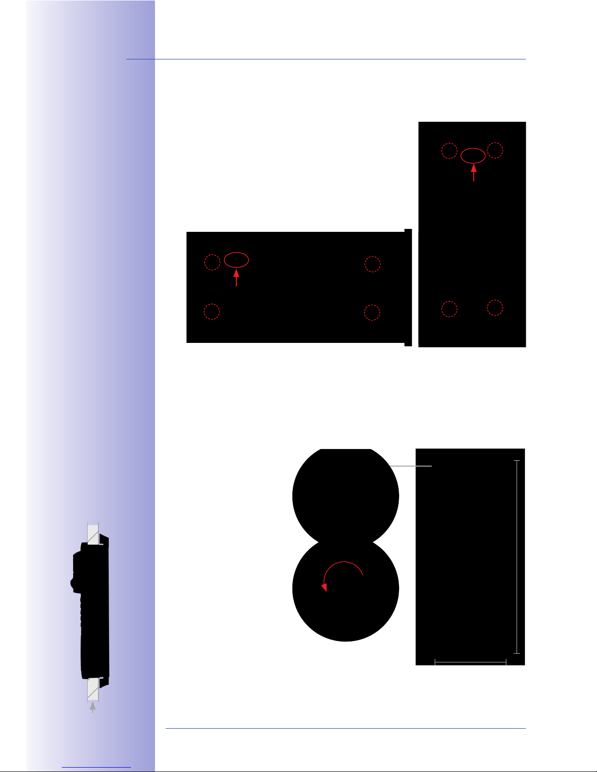
70/148
T24 System Manual Part 1: Installation
© MOBOTIX AG • Security-Vision-Systems • Made in Germany
www.mobotix.com • [email protected]
2.3.3 Attaching The Housing
On-Wall (Fig. Triple Housing)
Drill the four holes and insert the screw anchors (drilling template
is included). Ensure that the ‘Oben/Top’ label points upwards
(applies to horizontal and vertical installation). Attach the
on-wall housing using four Torx screws and the supplied
Torx wrench.
Cavity (Fig. Triple Housing)
When installing the housing in a cavity wall, tighten the cross-head screws embedded in
the housing corners until the four retaining wings swing out and clamp the housing tightly
to the cavity wall.
Ve t al insta lation
TOP
Horizontal installation
zontale Montage
TOP
P
[$#)&22&/<$ -*<< +5 16'$22
) '. X ))R)*0. 9X ))
85$ #$V3&#$; &'2+*<<*+&"'
">$' '@ 5*2 +5$ ("<<"-&'@
; )$'2&"'2 P-&;+5 0 5$&@5+Q,
D&'@<$ 5"32 '@, EEX 0 E9Y ))
C"3/<$ 5"32 '@, EEX 0 9EF ))
8#&><$ 5"32&'@, EEX 0 IEF ))
Xe9X ))
Retaining wings
for cavity installation
117 mm
318 mm
Page 71
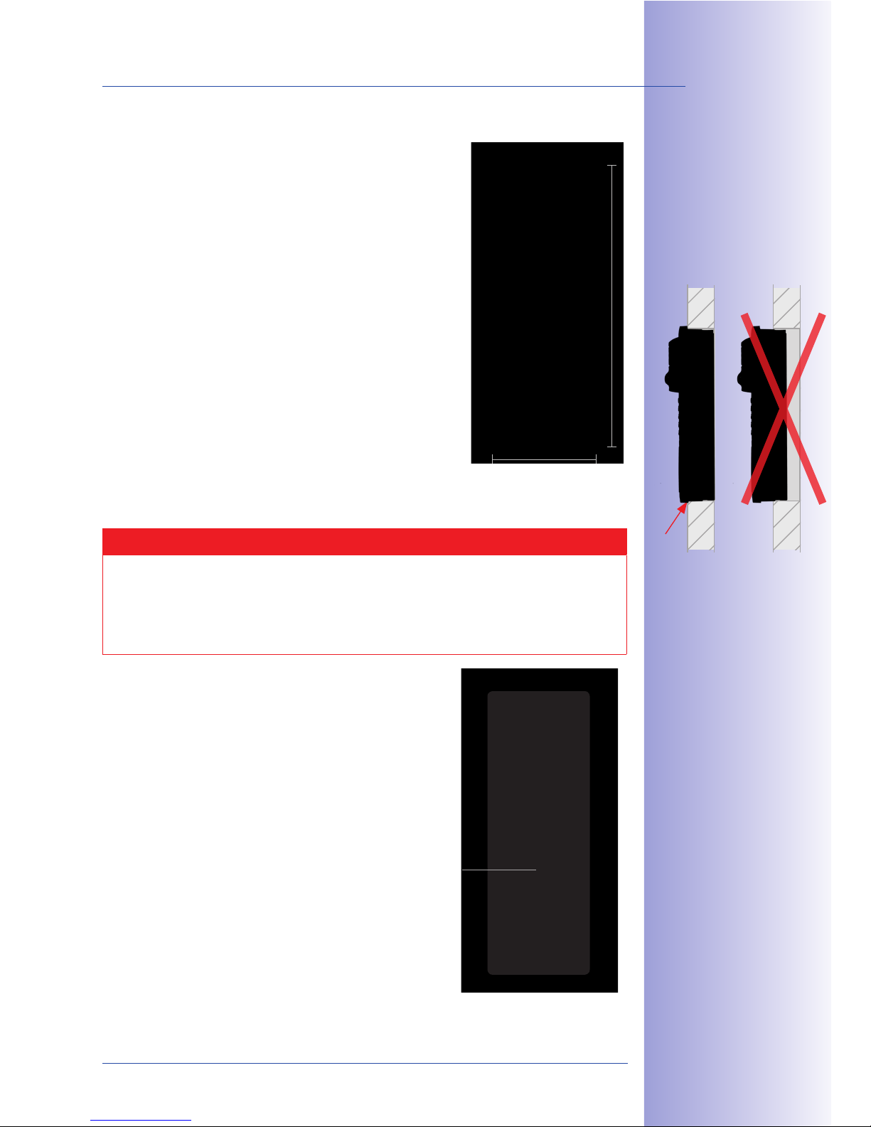
71/148
Mounting The Frame And Housing
© MOBOTIX AG • Security-Vision-Systems • Made in Germany
www.mobotix.com • [email protected]
In-Wall (Fig. Triple Housing)
Connect the housing with the subsurface so that the bars fitted
to the edge are still visible. The required opening should be
116 x 318 mm. Turn the housing over and use it as a template
to mark the holes.
Dimensions for installation opening (W x H x D):
• Single housing: 117 x 129 x at least 52 mm
• Double housing: 117 x 218 x at least 52 mm
• Triple housing: 117 x 318 x at least 52 mm
Caution
Make sure to install the in-wall housing carefully using the inserted protective
cardboard so that it is not deformed by any pressure from the surrounding material.
Otherwise the frame may not be installed properly and may not be sealed against
the weather.
To prevent cement or plaster from soiling the inside of the
housing, insert the supplied protective cardboard again
before installing the housing in the subsurface of the wall.
After you have secured the in-wall housing, you can easily
remove the protective cardboard by pushing through the
pre-punched opening and simply pulling out the cardboard.
117 mm
318 mm
B&'+, 83#' +5$
'?-*<< 2"16$+ "7$# *';
32$ &+ *2 * +$)><*+$
+" )*#6 +5$ 5"<$
d$*; '@ $;@$ "( 5"32&'@
W325 -&+5 -*<<
Pierce opening hole
and pull through cardboard
Page 72
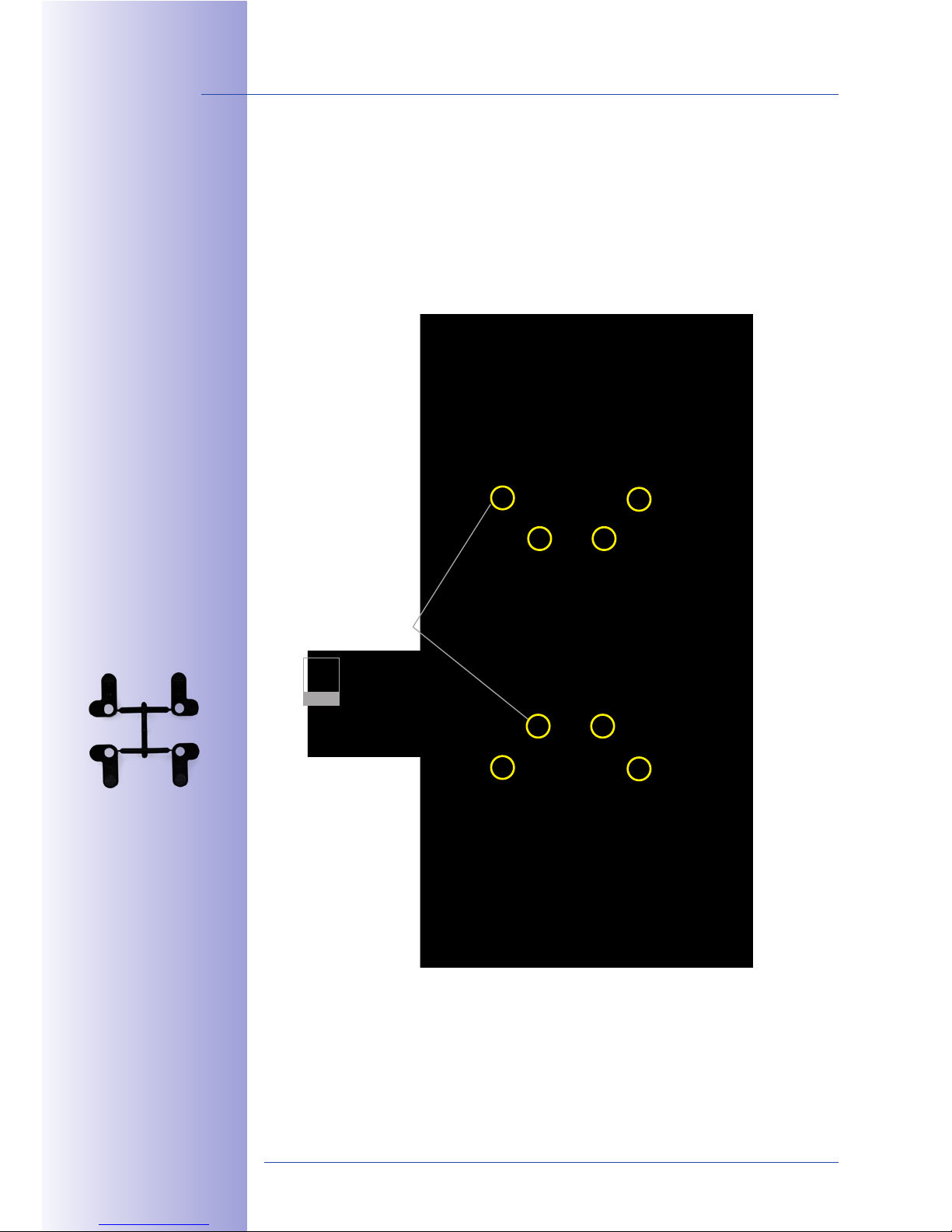
72/148
T24 System Manual Part 1: Installation
© MOBOTIX AG • Security-Vision-Systems • Made in Germany
www.mobotix.com • [email protected]
2.3.4 Cabling In The On-Wall Housing
To prevent cables from being damaged when you mount the frame or the T24 modules,
make sure that the cables are routed correctly. Please refer to the example cabling shown
in the figure below. The packaging material contains four blue cable binders that can be
secured to eight designated cable receptacles using screws (recommendation: cross slot
PH 2x100).
8 mm
Mounting points
for cable binders
(8x, marked yellow)
D$7$#*< 1*/<$ /&';$#2
*#$ &'1<3;$; &' +5$
;$<&7$#4 6&+
Page 73
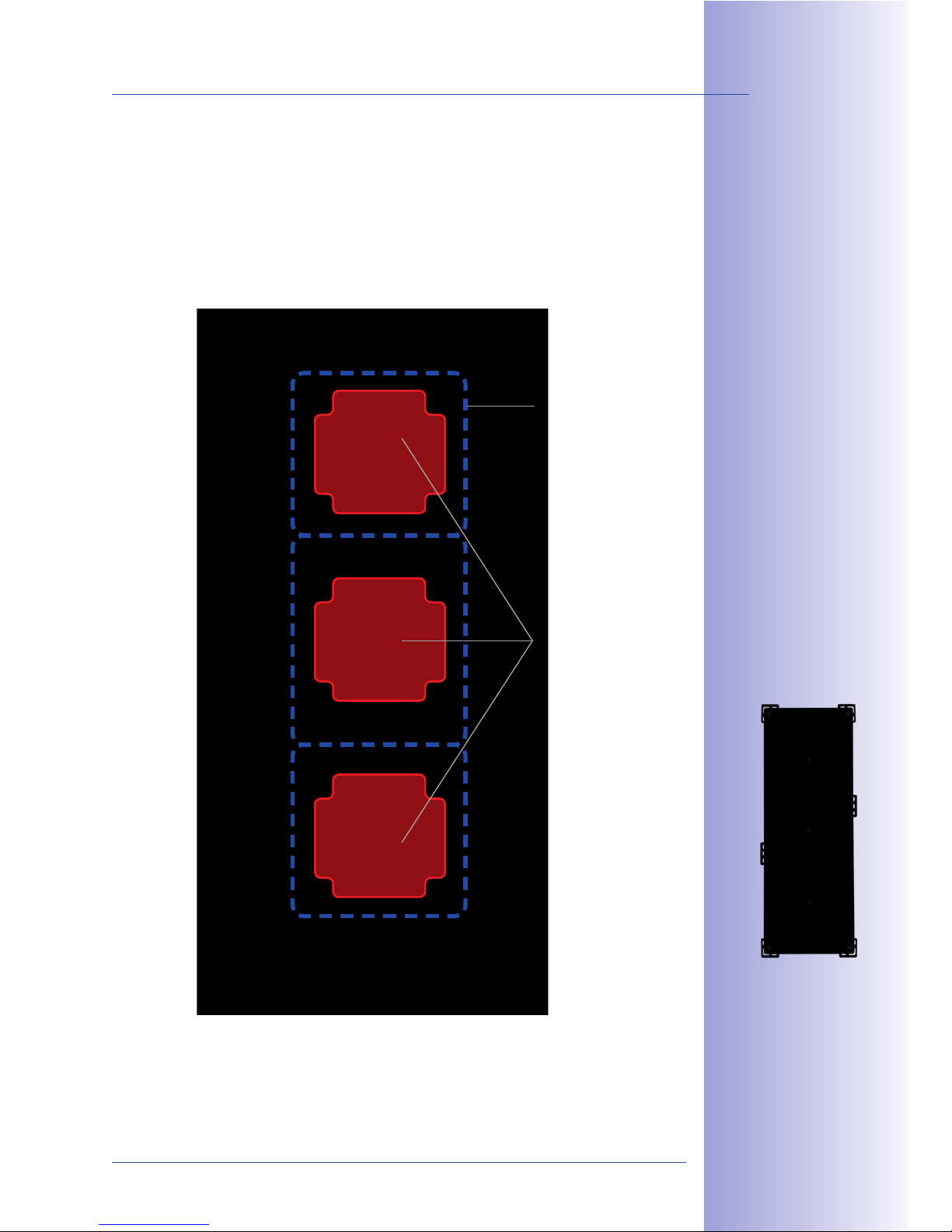
73/148
Mounting The Frame And Housing
© MOBOTIX AG • Security-Vision-Systems • Made in Germany
www.mobotix.com • [email protected]
The T24 housing (on-wall/in-wall) provides sucient space for cable reserves (see the blue
dashed line in the figure).
The red areas are ‘o-limits areas’. No cables should be placed in this area (risk of damage
to cables when module is mounted).
Cable guide
(dotted blue)
O-limits
for cable guide
85$ &'?-*<< 5"32&'@
>#"7&;$2 23(]1&$'+
2>*1$ e +5$#$ *#$ '"
"((?<&)&+2 *#$*2
Page 74
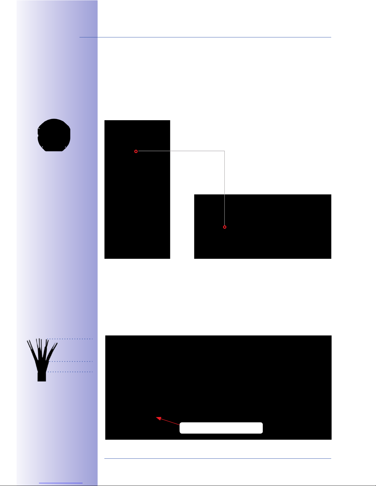
74/148
T24 System Manual Part 1: Installation
© MOBOTIX AG • Security-Vision-Systems • Made in Germany
www.mobotix.com • [email protected]
2.3.5 Mounting The Terminal Board And Fitting The Network Cable
Mounting The Ethernet Terminal Board
Screw the board into the housing (flattened side is at the bottom). The terminal board
must be placed behind the camera module. This step is not necessary for the T24 version
with Mx2wire+ technology (two-wire cable replaces Ethernet cable), as an Ethernet terminal
board is not required.
Stripping And Fitting The Network Cable
The Ethernet terminal board provides a link from the network installation cable to the
special patch cable of the camera module mounted directly above.
Connect the eight wires of the installation cable (with stripped ends) to the corresponding
contacts on the terminal board in accordance with the sticker (fig. standardized color coding
according to TIA-568B). Fasten the network cable so that its shielding rests on the terminal
board contact field (using the enclosed cable tie).
="# 1"''$1+&'@ $0+$#'*<
;$7 1$2A *' $0>*';$;
+$#) '*< /"*#; P89:?
M[8?KMQ 1*' /$
)"3'+$; ' ><*1$ "( +5$
`+5$#'$+ +$#)&'*< /"*#;
P2$$ D$1+&"' 9.X.9Q
Attachment of board for vertical
and horizontal installation
\5$16 -5$+5$# +5$
'$+-"#6 1*/<$ *+
+5$ "+5$# $'; [email protected]
["` 2-&+15Q &2 -&#$;
*11"#; '@ +" cJFa "#
cJFN P2$$ 2+ 16$#Q
="<<"- +5$2$
)$*23#$)$'+2 -5$'
2+# >> '@ +5$ 1*/<$
Z 9c ))
EG ))
Network cable retainer
Page 75
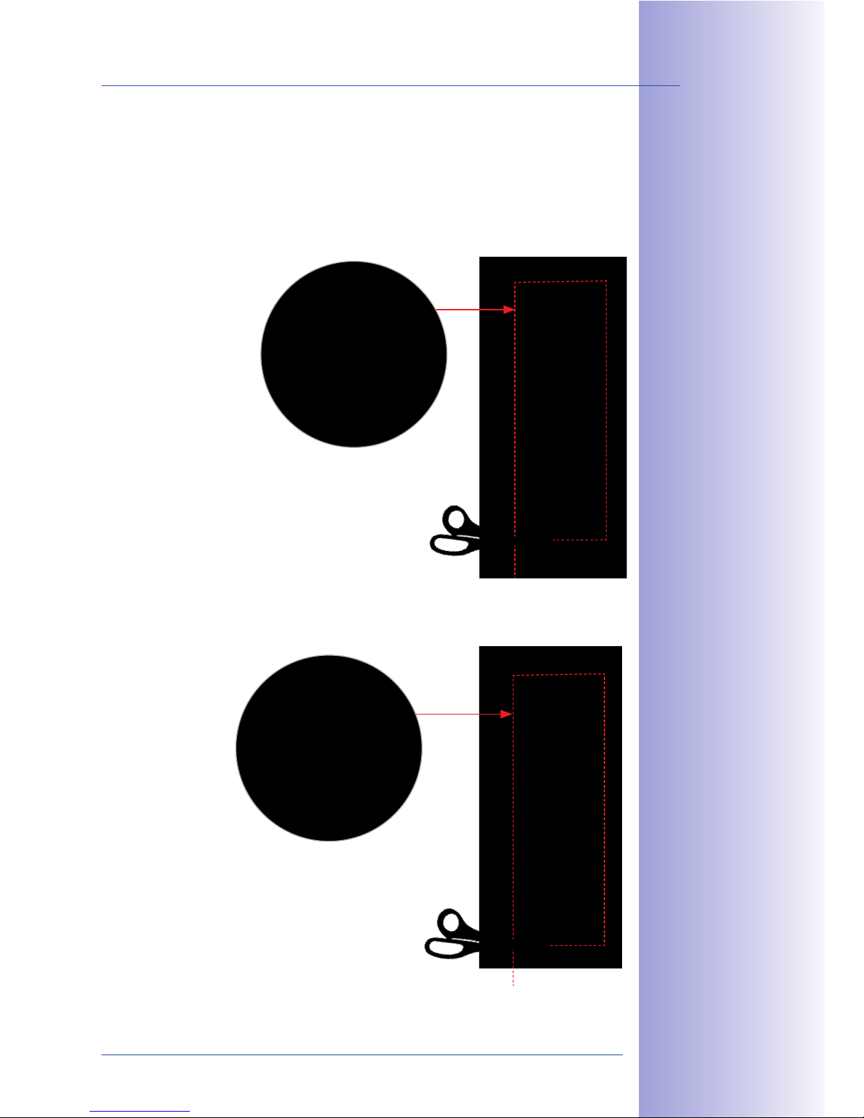
75/148
Mounting The Frame And Housing
© MOBOTIX AG • Security-Vision-Systems • Made in Germany
www.mobotix.com • [email protected]
2.3.6 Sticking The Seal In Place
Remove the protection film and stick the supplied seal all the way round the inner housing
frame, ensuring it fits exactly and taking care not to leave any gaps.
Use a pair of scissors to remove any surplus material. Please ensure that the adhesive
surface is clean, dry and free of grease.
On-Wall Housing
In-Wall And Cavity Housing
D+ 16 +5$ 2$*< +"
+5$ &''$# (#*)$ *2
25"-' &' +5$ ]@3#$
D+ 16 +5$ 2$*< +"
+5$ &''$# (#*)$ *2
25"-' &' +5$ ]@3#$
Page 76
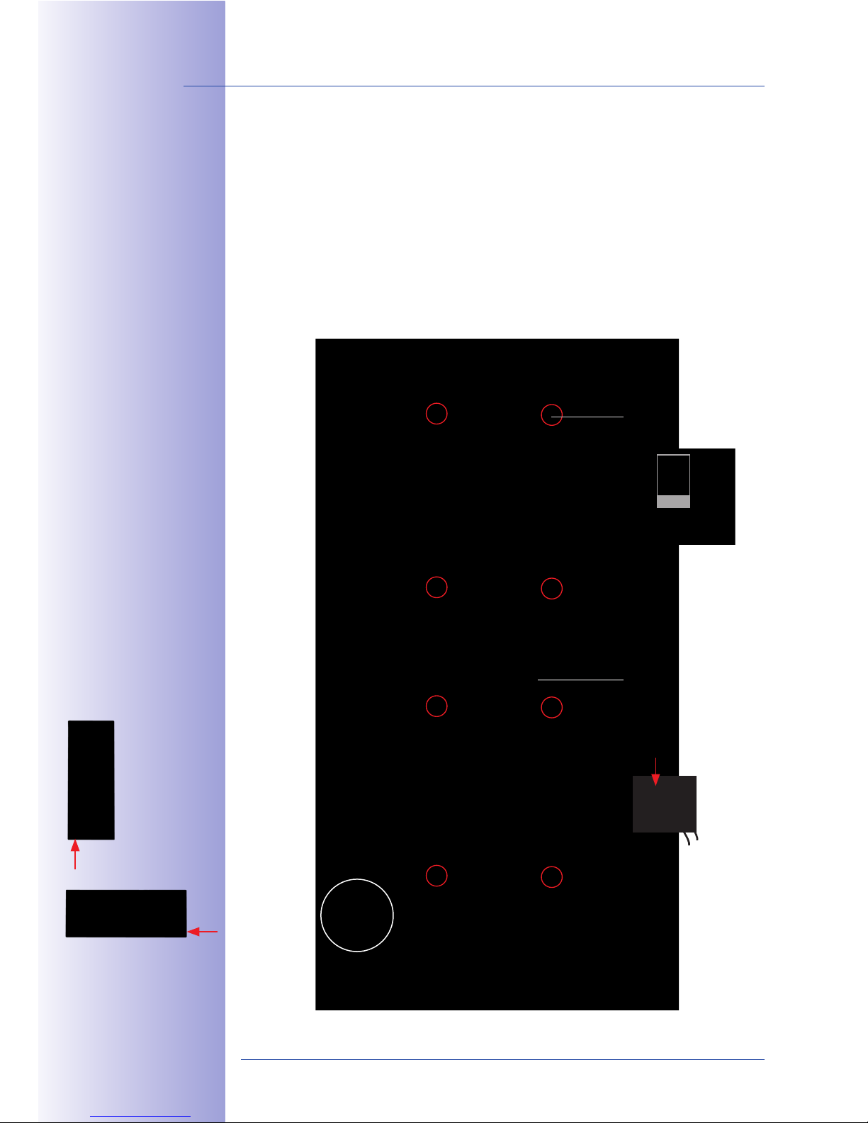
76/148
T24 System Manual Part 1: Installation
© MOBOTIX AG • Security-Vision-Systems • Made in Germany
www.mobotix.com • [email protected]
2.3.7 Attaching The Frame And Connecting The Anti-Theft Protection
Before the T24 modules can be clicked into the frame, you must screw the frame onto the
housing (recommendation: cross slot PH 2x100) and lay the black anti-theft protection cable
to the inside of the building according to your selected connection option, for example, to the
T24-DoorMaster (you may also need to extend the cable). When you attach the frame, make
sure that the two openings for the special MOBOTIX key - which is used to remove the door
station modules - are located either on the bottom left (vertical mount) or on the bottom right
(horizontal mount), and that the maximum torque for the frame screws is not exceeded.
On-Wall (Fig. Triple Housing)
=#*)$ *<&@')$'+
("# 7$#+ 1*< *';
5"#&k"'+*< )"3'+&'@
P#$; *##"- >"&'+2
+" +5$ 6$45"<$Q
Screw 8x,
marked red,
max. 100 Ncm
Guide anti-theft
protection cable for
T24-DoorMaster
(directly or extend
with the two individual
wire connectors)
Insert wire (not stripped)
(1) and press down
cutting clamp
with pliers (2)
Note slot for key
1
2
12 mm
Page 77
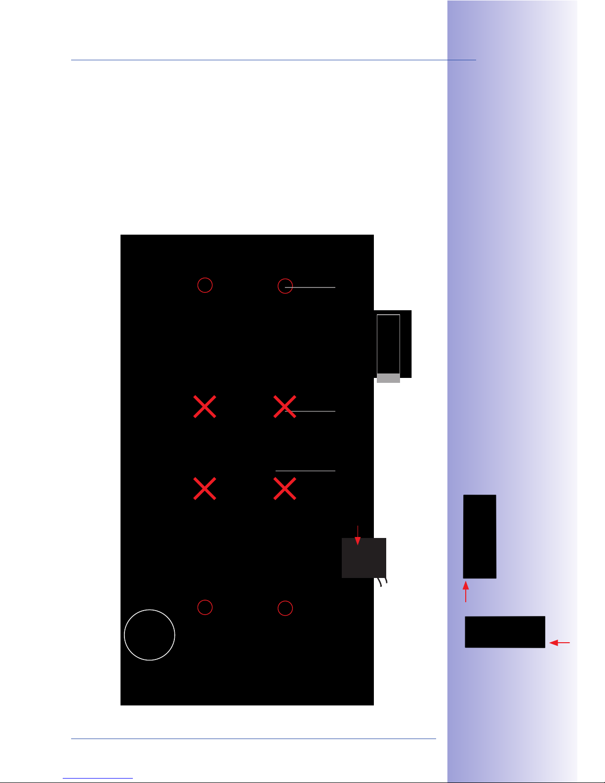
77/148
Mounting The Frame And Housing
© MOBOTIX AG • Security-Vision-Systems • Made in Germany
www.mobotix.com • [email protected]
Cavity And In-Wall (Fig. Triple Housing)
Please note that in this case the module frame may only be screwed onto the four outermost
positions on the housing (max. torque: 40 Ncm).
=#*)$ *<&@')$'+
("# 7$#+&1*< *';
5"#&k"'+*< )"3'+&'@
P#$; *##"- >"&'+2
+" +5$ 6$45"<$Q
Screw 4x,
marked red,
max. 40 Ncm
NOT USABLE
Guide anti-theft
protection cable to
the T24-DoorMaster
(directly or extend
with the two individual
wire connectors)
Note slot for key
Insert wire (not stripped)
(1) and press down
cutting clamp
with pliers (2)
1
2
30 mm
Page 78
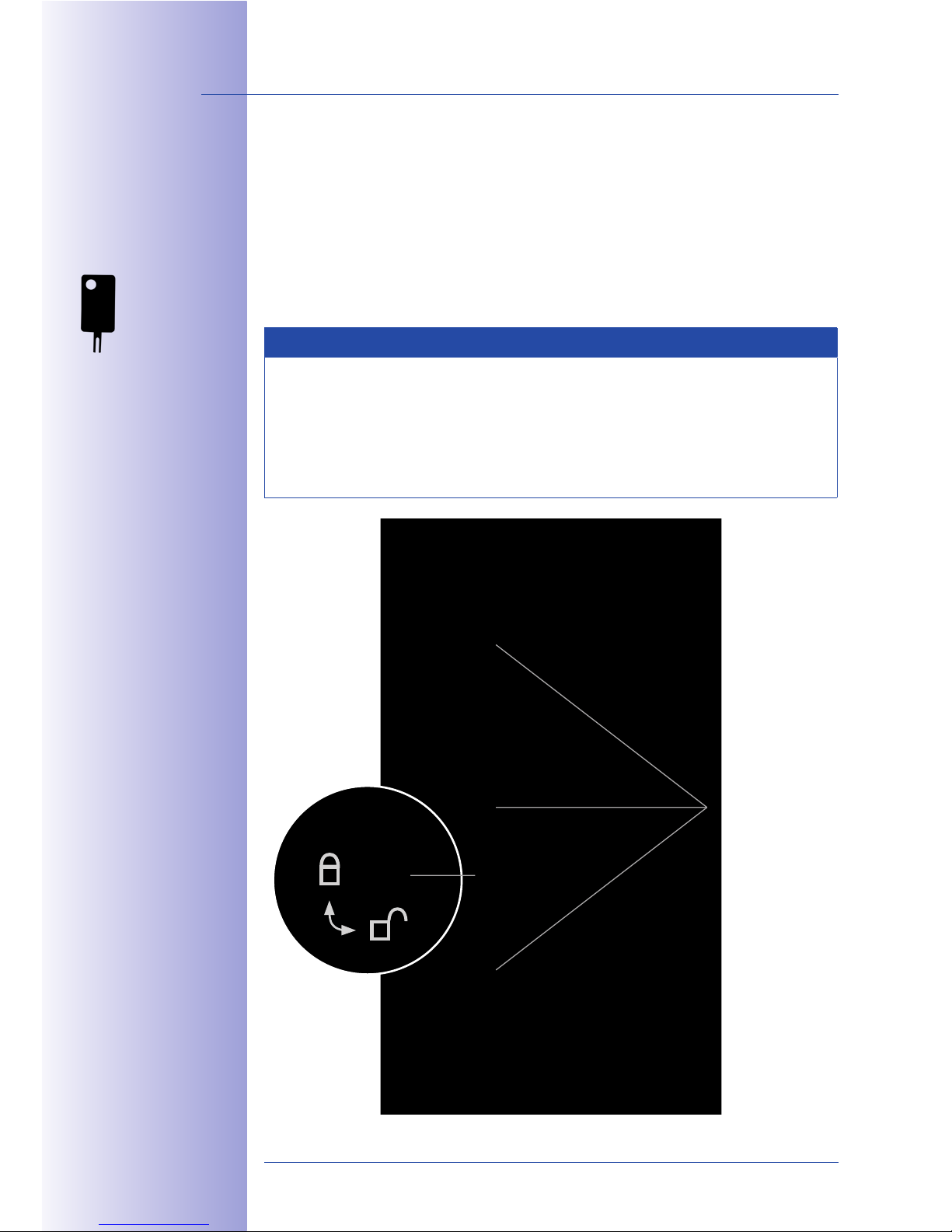
78/148
T24 System Manual Part 1: Installation
© MOBOTIX AG • Security-Vision-Systems • Made in Germany
www.mobotix.com • [email protected]
2.3.8 Mechanical Anti-Thef t Protection Lock
In the default configuration of the door station, anti-theft protection is not activated in the
frame. This allows modules that have already been integrated to be removed again during
the installation, just using the special key that has been supplied.
Insert the key into the opening provided and apply light pressure. The red retaining collars
on the left or lower side of the frame (depending on whether the frame is mounted vertically
or horizontally) loosen and release the modules.
Notes
To activate the mechanical anti-theft protection lock, the module above the red
rotary button (triple frame: center module, double frame: upper/left module) must
be released from the frame.
Important: After the installation, check the wiring (see Section 2.8.1) and only then
activate the anti-theft protection lock.
D>$1&*< 6$4
Retaining tabs
Red rotary button
Page 79
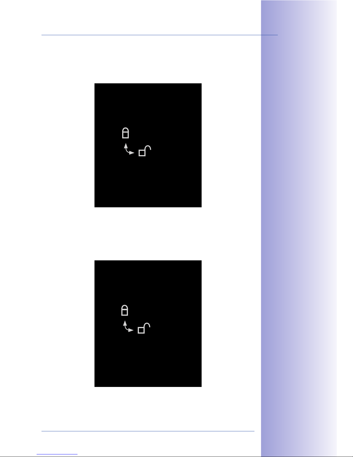
79/148
Mounting The Frame And Housing
© MOBOTIX AG • Security-Vision-Systems • Made in Germany
www.mobotix.com • [email protected]
Activating
The Anti-Theft Protection Lock
Use a screwdriver to turn the red rotary button inside the frame 90 degrees clockwise.
When anti-theft protection is activated, the arrow points to the ‘closed lock’ symbol.
Deactivating The Anti-Theft Protection Lock
Turn the red rotary button so that the arrow points to the ‘opened lock’ symbol.
K' +5&2 >"2&+&"'A 32 '@
+5$ 2>$1&*< 6$4 *<"'$ +"
#$<$*2$ +5$ )";3<$2 (#")
+5$ (#*)$ &2 '"+ >"22&/<$
K' +5&2 >"2&+&"'A 4"3
1*' 32$ +5$ 2>$1&*< 6$4
*<"'$ +" #$<$*2$ +5$
)";3<$2 (#") +5$ (#*)$
Page 80
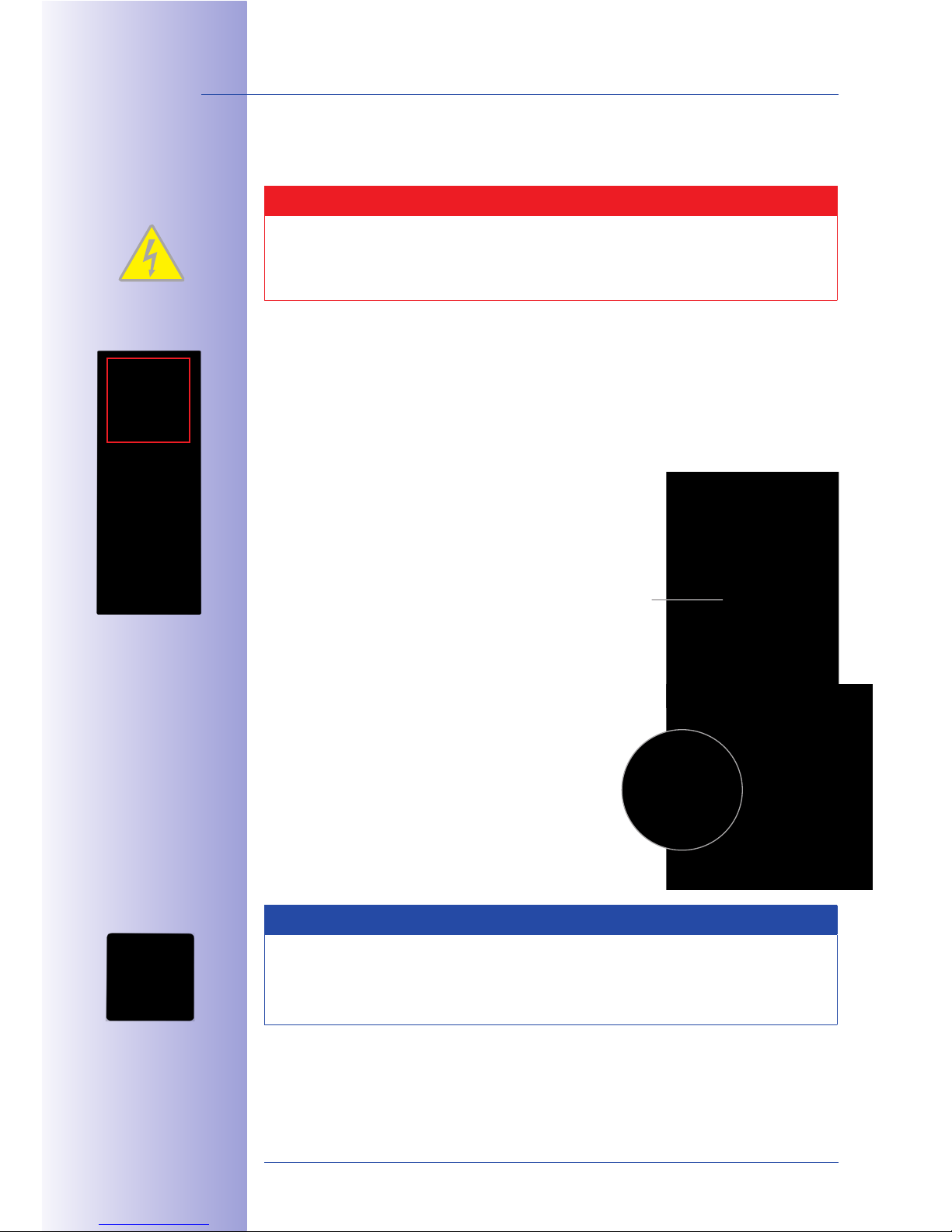
80/148
T24 System Manual Part 1: Installation
© MOBOTIX AG • Security-Vision-Systems • Made in Germany
www.mobotix.com • [email protected]
2.4 Installing The T24 Modules
Caution
Beware of short circuits: When you install the modules, the MxBus cable should
not be live, which means that the network cable should still be disconnected from
the PoE switch.
2.4.1 Installing The Camera Module T24-CamCore
Standard Network Connection
The Ethernet terminal board is used to connect the door station for the T24 version without
Mx2wire+ technology. It connects the short, pre-installed camera patch cable with the
eight split-out wires of the network installation cable (for installation, see Section 2.2.5).
1. Ensure that the seal is fitted to the camera module.
2.
Connect the supplied MxBus cable to the push terminal
on the rear wall of the camera. Remove approximately
5 mm of insulation from the cable ends and push
into the terminal.
• Red wire to + terminal
• Blue wire to - terminal
Note
To connect the MxBus cable of the T24-DoorMaster, the two free MxBus terminals
of the camera module can be used as an alternative to the MxBus terminals on the
keypad or info module (see Section 2.5).
Seal
C" !"# 2-*> +5$
U *'; ? - #$2
S5$' 32&'@ * ;&(($#$'+?
1"<"#$; 1*/<$A )*6$
23#$ +5$ 1"##$1+
>"<*#&+4 &2 #"3+$;
Page 81
81/148
Installing The T24 Modules
© MOBOTIX AG • Security-Vision-Systems • Made in Germany
www.mobotix.com • [email protected]
3. Guide the MxBus cable (to be shortened accordingly) into the housing and under
the frame so that it can be easily connected to the keypad later on. Insert the
pre-installed camera module patch cable into
the RJ45 port on the terminal board.
4.
First of all, insert the right side of the module into
the frame and then press firmly on the left side,
until the module audibly clicks into place.
Control click: If you do not hear a click, this means that the module is not properly locked
into place. In this case, repeat the last steps, making sure that no cable or foreign object
in the housing is preventing the module from properly clicking into place.
[*4 *++$'+&"' +" +5$
"((?<&)&+2 *#$*2
("# 1*/<$2 #$2$#7$2
P2$$ D$1+&"' 9.I.:Q
MxBus cable
for the keypad
Patch cable
Click
S&+5 5"#&k"'+*<
)"3'+&'@A +5$ )";3<$2
)32+ ]#2+ /$ >"2&+&"'$;
$# #&' #"( *'; +5$'
>#$22$; ;"-'-*#;2 ]#)<4
Page 82
82/148
T24 System Manual Part 1: Installation
© MOBOTIX AG • Security-Vision-Systems • Made in Germany
www.mobotix.com • [email protected]
Network Connection Via Mx2wire+ Technology
An Ethernet terminal board is not required for the T24 door station with Mx2wire+ technology.
Instead, the camera module is connected to the T24-Info2wire+ info module via a MOBOTIX
patch cable.
1. Ensure that the seal is fitted to the camera module.
2. Remove the pre-installed camera module patch
cable and instead insert the supplied, longer patch
cable into the camera housing. Make sure that
the blue rubber sealing ring is in the correct final
position.
3. Feed the MxBus two-wire cable from the camera
(installation as described in Section 2.4.1) together
with the newly fitted patch cable into the housing
and under the frame, so that the MxBus cable can
be fastened to the keypad board and the patch cable
to the info module.
Seal
Attach the longer patch cable for the T24-Info2wire+
info module
Page 83
83/148
Installing The T24 Modules
© MOBOTIX AG • Security-Vision-Systems • Made in Germany
www.mobotix.com • [email protected]
4.
First of all, insert the right side of the module into the frame and then press firmly
on the left side, until the module audibly clicks into place.
Control click: If you do not hear a click, this means that the module is not properly locked
into place. In this case, repeat the last steps, making sure that no cable or foreign object
in the housing is preventing the module from properly clicking into place.
Click
Page 84
84/148
T24 System Manual Part 1: Installation
© MOBOTIX AG • Security-Vision-Systems • Made in Germany
www.mobotix.com • [email protected]
2.4.2 Installing The T24-KeypadRFID
Please pay attention to the dierent system wiring configurations that apply (described in
Section 2.1), depending on whether or not the T24-DoorMaster and external devices such
as a light are used.
1. Ensure that the seal is fitted to the keypad.
2.
Loosen the rear cover plate (using a small screwdriver
or similar tool) and remove it. You now have a clear
view of the connectors located directly on the keypad
board.
3.
Remove approximately 5 mm of insulation from each
of the cables to be connected and feed each cable
through one of the wire apertures in the housing
(piercing the rubber membrane).
Seal
Page 85
85/148
Installing The T24 Modules
© MOBOTIX AG • Security-Vision-Systems • Made in Germany
www.mobotix.com • [email protected]
4. Connect the two MxBus cables that come from the camera module to the
keypad board.
• Red wire to MX + terminal
• Blue wire to MX - terminal
5. Connect two new MxBus cables to the keypad
board, and subsequently connect these to the
info module to power its backlighting. Make sure
that the cables are of the required length and that
they are routed correctly (does not apply to
T24-Info2wire+ info module).
• Red wire to MX + terminal
• Blue wire to MX - terminal
Note
If the info module is connected to the MxBus connector of the door camera T24CamCore, the two MxBus cables of the T24-DoorMaster can be connected to the
keypad instead.
If no lighting function is required for the info module at all, the MxBus cables do not
need to be connected to this module.
D$$ +5$ 1 #13&+ "7$#7 $;&*@#*) "' +5$ '$0+ >*@$
C" !"# 2-*> +5$
>"<*#&+4 "( +5$ U
*'; ? !0N32 -&#$2
Page 86
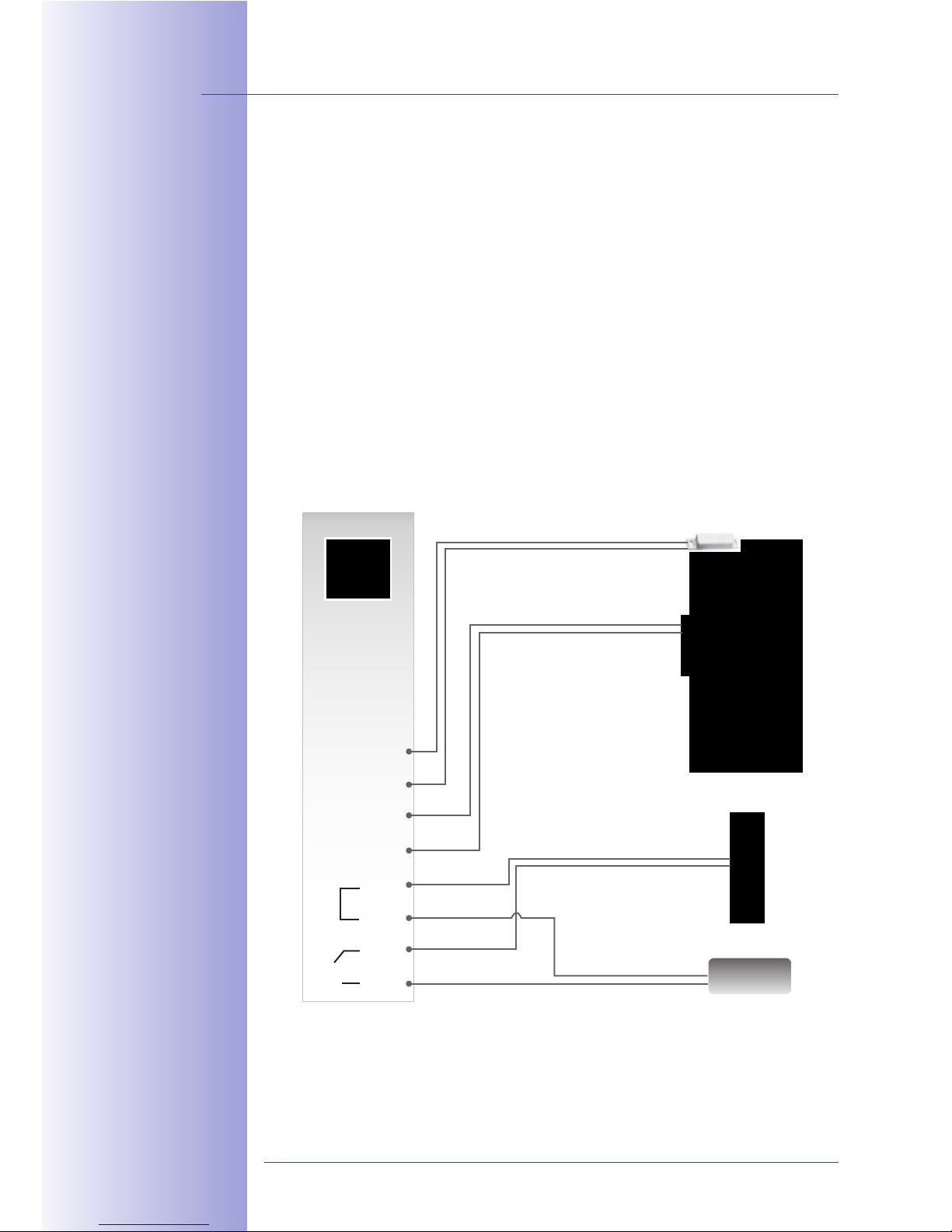
86/148
T24 System Manual Part 1: Installation
© MOBOTIX AG • Security-Vision-Systems • Made in Germany
www.mobotix.com • [email protected]
6. Connect all the other connection cables (if present):
Standard door opener or relay (for lights etc.):
• First wire to COM terminal
• Second wire to OUT A terminal
External power supply for door opener or power relay (for example, 12 V AC):
• First wire to OUT B terminal
• Second wire to COM terminal
‘Door opened/closed’ door contact (reed switch):
• First wire to IN 1+ terminal
• Second wire to IN 1- terminal
‘Door lock unlocked/locked’ door lock switch:
• First wire to IN 2+ terminal
• Second wire to IN 2- terminal
T24-KeypadRFID
MX +
MX -
MX +
MX -
IN 1+
IN 1-
IN 2+
IN 2-
COM
COM
OUT A
OUT B
Connector for external devices (light relay, etc.)
and 12 V power supply unit
e.g. 12 V AC
Power supply
Door opener/power relay
Door
Door contact
Door lock switch
Page 87
87/148
Installing The T24 Modules
© MOBOTIX AG • Security-Vision-Systems • Made in Germany
www.mobotix.com • [email protected]
7. Put the cover plate back on.
8. First of all, insert the right side of the module into
the frame. Then press firmly on the left side, until
the module audibly clicks into place.
Control click: If you do not hear a click, this means that the module is not properly locked
into place. In this case, repeat the last steps, making sure that no cable or foreign object
in the housing is preventing the module from properly clicking into place.
Caution
Do not activate the anti-thef t protection lock until you have checked the wiring
(see Section 2.8.1). Also test the functionality of the anti-theft protection (see
Section 2.4.6).
Click
M'<4 >#$22 ]#)<4 "'
+5$ $;@$ "( +5$ 6$4>*;
P'"+ ' +5$ )&;;<$Q
Page 88
88/148
T24 System Manual Part 1: Installation
© MOBOTIX AG • Security-Vision-Systems • Made in Germany
www.mobotix.com • [email protected]
2.4.3 Installing The Info Module T24-Info
The info field in the info module of the T24 door station without Mx2wire+ technology is
equipped with permanent LED backlighting supplied via MxBus.
1. Ensure that the seal is fitted to the info module.
2.
Loosen the rear cover plate (using a small screwdriver
or similar tool) and remove it. You now have a clear
view of the connectors located directly on the info
module board.
3.
Remove approximately 5 mm of insulation from each
of the cables to be connected and feed each cable
through one of the wire apertures in the housing
(piercing the rubber membrane with the cable).
Seal
Page 89
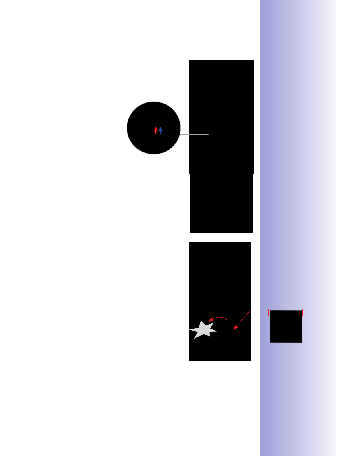
89/148
Installing The T24 Modules
© MOBOTIX AG • Security-Vision-Systems • Made in Germany
www.mobotix.com • [email protected]
4.
Connect the two MxBus cables that come from the keypad to the info module board.
• Red wire to MX + terminal
• Blue wire to MX - terminal
5. Put the cover plate back on.
6. First of all, insert the right side of the module into
the frame. Then press firmly on the left side, until
the module audibly clicks into place.
Control click: If you do not hear a click sound, this means that the module is not properly
locked into place. In this case, repeat the last steps, making sure that no cable or foreign
object in the housing is preventing the module from properly clicking into place.
a2 *' *<+$#'*+&7$ +" +5$
+$#)&'*<2 "' +5$ 6$4>*;
"# &'(" )";3<$A 4"3 1*'
32$ +5$ +-" (#$$ !0N32
+$#)&'*<2 "( +5$ 1*)$#*
)";3<$ +" 1"''$1+
+5$ 89:?C""#!*2+$#
P2$$ D$1+&"' 9.cQ
Click
a<-*42 )"3'+ +5$
)";3<$ 2" +5*+ +5$ /*#
-&+5 +5$ !MNM8KO
<$++$#&'@ &2 *+ +5$ +">
Page 90
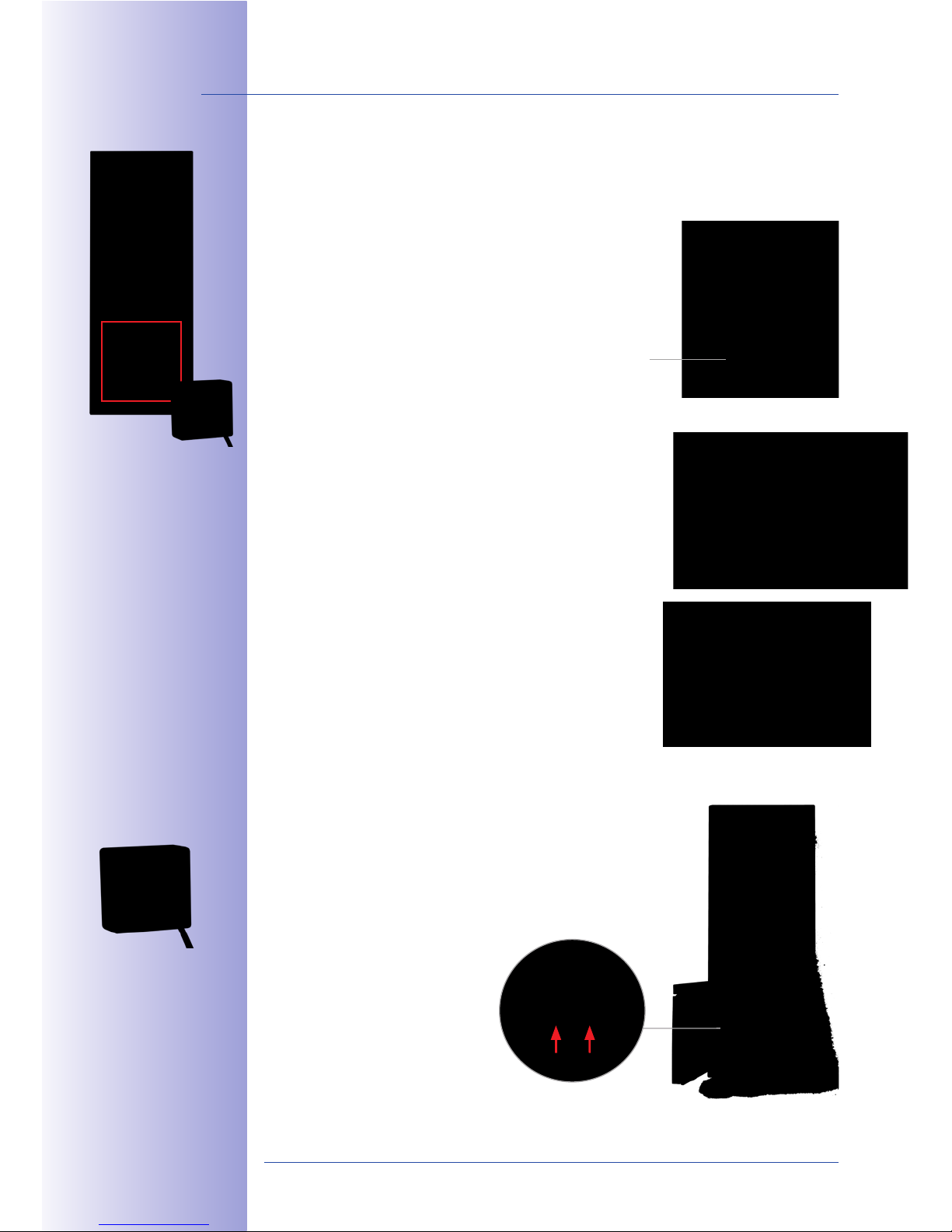
90/148
T24 System Manual Part 1: Installation
© MOBOTIX AG • Security-Vision-Systems • Made in Germany
www.mobotix.com • [email protected]
2.4.4 Installing The Info Module T24-Info2wire+
The info module with integrated Mx2wire+ technology is used to connect the door station
to the network via a two-wire cable such as a bell wire and has an info field with permanent
LED backlighting.
1. Ensure that the seal is fitted to the info module.
2.
Loosen the rear cover plate (using a small screwdriver
or similar tool) and remove it. You now have a clear
view of the connectors located directly on the info
module board.
3.
Remove approximately 5 mm of insulation from each
of the cables to be connected and feed each cable
through one of the
wire apertures
in the housing
(piercing the rubber membrane with the cable).
4.
Connect the two-wire cable, which leads to the separate
T24-Info2wire+ unit in the building, to the board.
• First wire to Data 1 terminal
• Second wire to Data 2 terminal
Seal
89:?K'("9-&#$U ';""#
3'&+ P("# '2+*<<*+&"'A
2$$ D$1+&"' 9.JQ
Page 91
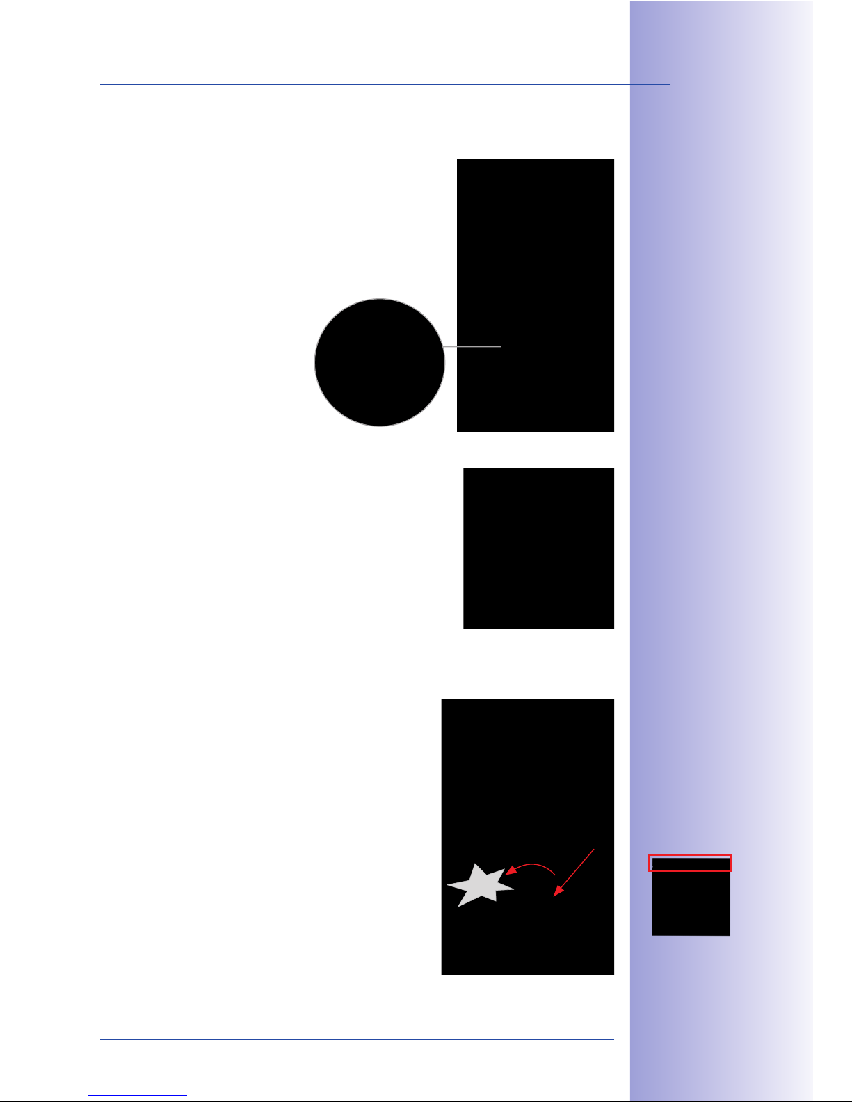
91/148
Installing The T24 Modules
© MOBOTIX AG • Security-Vision-Systems • Made in Germany
www.mobotix.com • [email protected]
5. Remove the blue sealing plug on the module. Feed the RJ45 connector of the
(extended) camera patch cable into the housing and insert it into the RJ45 port.
Make sure that the rubber sealing ring on the patch
cable is in the correct final position.
6. Put the cover plate back on.
7.
First of all, insert the right side of the module into
the frame. Then press firmly on the left side, until
the module audibly clicks into place.
Control click: If you do not hear a click, this means that
the module is not properly mounted. In this case, repeat
the last steps, making sure that no cable or foreign object
in the housing is preventing the module from properly
clicking into place.
Click
a<-*42 )"3'+ +5$
)";3<$ 2" +5*+ +5$ /*#
-&+5 +5$ !MNM8KO
<$++$#&'@ &2 *+ +5$ +">
Page 92
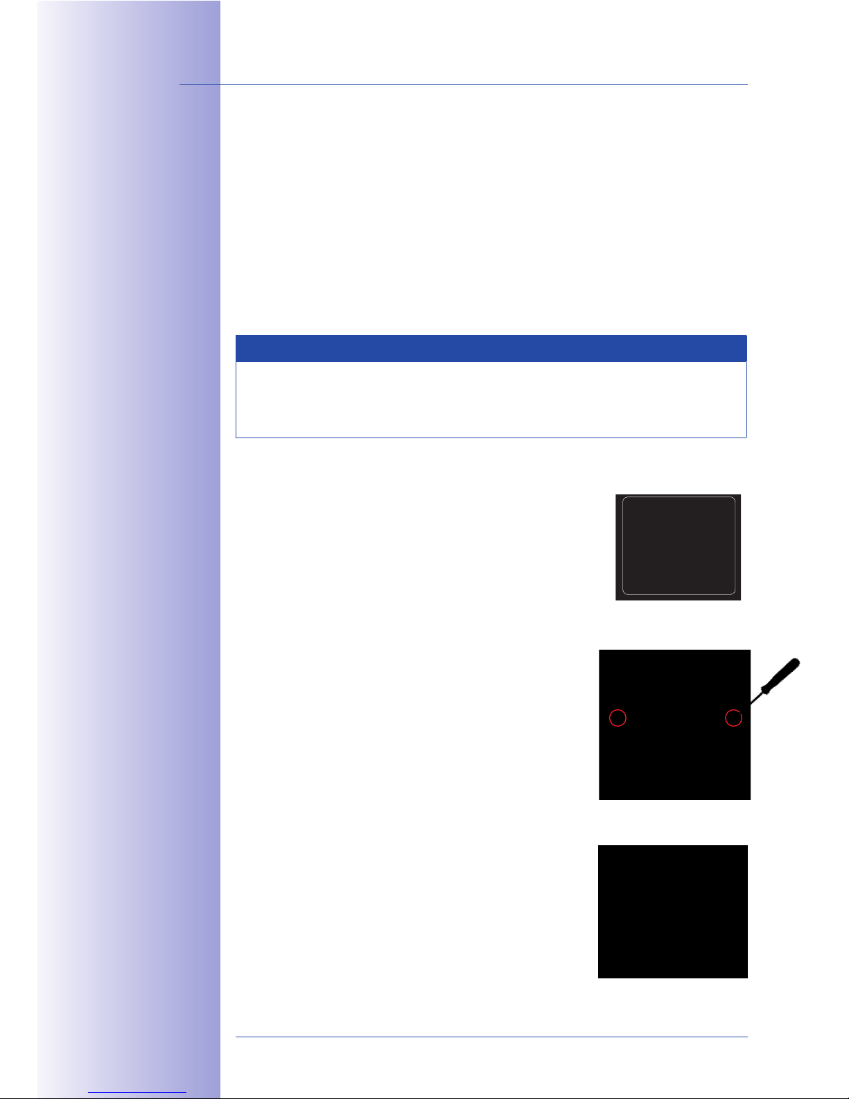
92/148
T24 System Manual Part 1: Installation
© MOBOTIX AG • Security-Vision-Systems • Made in Germany
www.mobotix.com • [email protected]
2.4.5 Labeling The Info Modules
The info module allows you to place a paper label or printer label behind the transparent
cover. You can use the enclosed permanent marker to personalize the paper insert by
adding your name, contact number, house number and so on.
You will find a PDF template on the MOBOTIX website to help you create your own label.
Simply add your personal data to the template and print it onto a sheet of A4 paper.
Then simply cut out your ‘doorbell label’ and insert it into the info module. Before you do
this, you will need to remove the info module from the door station frame (see Section
2.4.6 that follows).
Note
To create a doorbell label that goes with a keypad, please make sure to familiarize
yourself beforehand with how to configure and operate the door station (see
Part 2 of the System Manual).
Proceed as follows:
1. Make your personalized doorbell label. To do this,
customize the PDF template (Info_Panel.pdf) provided
on the MOBOTIX website (www.mobotix.com).
2.
Loosen the transparent protective cover on the info
module by hand or using a screwdriver, which you
position on the side (as shown in red) and use as a
lever.
3.
Tilt the protective cover downwards and remove the
silicone mat and paper insert.
Page 93
93/148
Installing The T24 Modules
© MOBOTIX AG • Security-Vision-Systems • Made in Germany
www.mobotix.com • [email protected]
4. Place your completed doorbell label (B) behind the transparent protective cover
(A). Insert the silicone mat (C) so that its smooth side is behind the label.
5. Position the protective cover at the bottom of the
info module (D) and press the top of the cover until
it clicks in place. Now, you can click the info module
back into the door station frame.
Info_Panel.pdf (available at www.mobotix.com)
Here are a few examples of doorbell labels that were created using the PDF file template.
To open the file requires Adobe Acrobat Reader (free).
Protective cover (A) Doorbell label (B) Silicon matt (C) Info module (D)
="<<"- +5$ 1"##$1+ "#;$#
P(#") <$(+ +" #&@5+Q
a;"/$ a1#"/*+
L$*;$#, ;"-'<"*; (#")
---.*;"/$.1")
Page 94
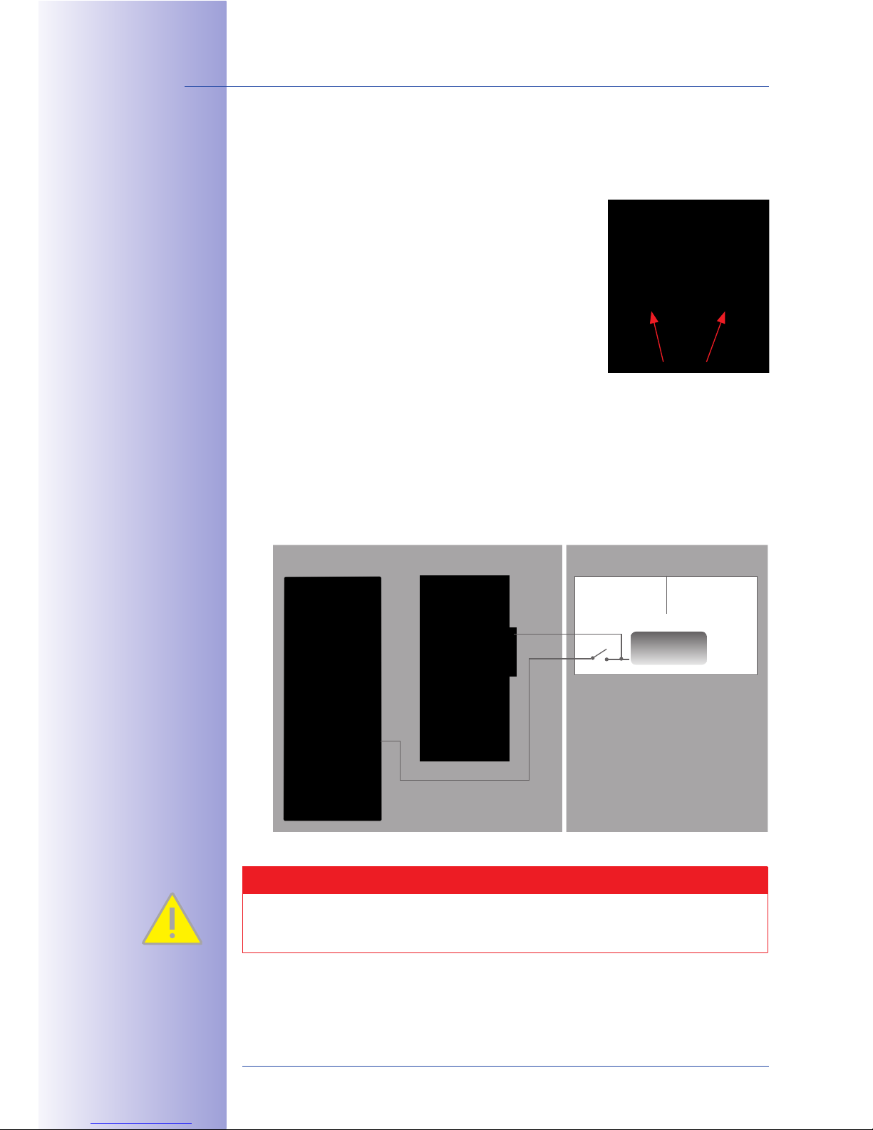
94/148
T24 System Manual Part 1: Installation
© MOBOTIX AG • Security-Vision-Systems • Made in Germany
www.mobotix.com • [email protected]
2.4.6 Removing And Exchanging Modules
If anti-theft protection has been activated (see Section 2.3.7), you will need to switch this
o before you can remove and exchange the modules.
1.
Switching o anti-theft protection on the T24-DoorMaster:
Press both buttons on the T24-DoorMaster at the same
time for ten seconds to deactivate the anti-theft
protection for 90 seconds (blue LED blinks). After
this, the protection will be automatically reactivated.
2. Switching o anti-theft protection when there is no T24-DoorMaster: Connect
the two cables of the anti-theft protection to the 12 V power supply of the electric
door opener via a switch. Anti-theft protection is deactivated for as long as the
voltage is applied (switch on).
Caution
The anti-theft protection must be disconnected from the voltage again (switch o)
after no more than five minutes in order to avoid an overload.
Hold at the same time until
the blue LED flashes
Outdoors Indoors
Door station
Switch box
Door
12 V
Power supply
S
Page 95
95/148
Installing The T24 Modules
© MOBOTIX AG • Security-Vision-Systems • Made in Germany
www.mobotix.com • [email protected]
3. Removing the modules: Insert the special MOBOTIX key provided into the split
opening on the module frame (bottom left or bottom right, depending on how it
has been mounted) and release the modules from
the frame by pushing the key in. All the modules in
the frame move slightly forward and can be removed.
Click (listen for “click” sound) any modules that you
do not wish to remove back into place.
Caution
Make sure that the anti-theft protection has been deactivated before you insert
the key, otherwise you risk damaging the frame.
Insert and
press
85$ 2>$1&*< 6$4 &2
'1<3;$; -&+5 +5$
;""# 2+*+&"'
Page 96
96/148
T24 System Manual Part 1: Installation
© MOBOTIX AG • Security-Vision-Systems • Made in Germany
www.mobotix.com • [email protected]
2.5 Installing The T24-DoorMaster
2.5.1 Overview Of Connectors
The T24-DoorMaster is connected to the door station via the MxBus two-wire cable and
the two wires of the anti-theft protection cable.
In addition, the four cables of the door signal contacts and the two cables of the electrically
operated door opening components (standard door opener, Mediator) can also be
connected to the T24-DoorMaster (see Section 1.2, Technical Specifications).
The main function of this innovative device is to control the door opener in a tamperproof manner and record the status of the door (open, closed, closed and locked). The
T24-DoorMaster, with its speaker that can be switched o, also functions as a doorbell.
It furthermore allows the door to be opened using a button and controls the anti-theft
protection in the T24 housing.
Thanks to its built-in batteries, which are kept fully charged via the MxBus cables, the
T24-DoorMaster is able to power both the keypad in the outdoor station and a connected
door opener for several hours in the case of power failure, therefore ensuring that the
door can still be accessed without a key.
K'+$@#*+$; $)$#@$'14
3'<"16&'@ (3'1+&"'
OUT -
IN -
IN 2+
IN 1+
OUT 1+
OUT 2+
MX +
MX -
Page 97
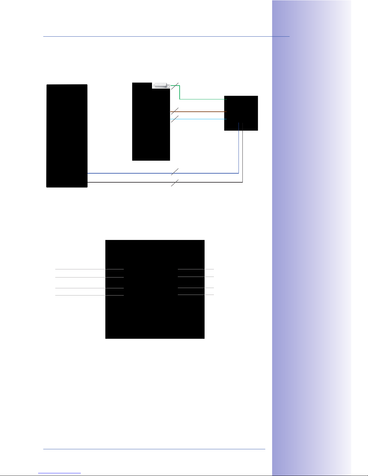
97/148
Installing The T24-DoorMaster
© MOBOTIX AG • Security-Vision-Systems • Made in Germany
www.mobotix.com • [email protected]
T24-DoorMaster System Overview
Supported Door Opener Versions
A standard door opener operated with 6 to 12 V AC can be connected directly to the T24DoorMaster and powered by its integrated battery pack. There is no need to connect an
additional power supply unit.
A door opener with an external power supply of up to 24 V AC/DC (max. 1 A) may also
be connected, as may the self-locking Mediator door lock.
MxBus (MX +)
Anti-theft protection (OUT 1+)
Anti-theft protection/
Door opener (OUT -)
Door lock switch/ Door contact (IN -)
Door contact (IN 1+)
Door opener (OUT 2+)
Door lock switch (IN 2+)
MxBus (MX -)
Door station T24-DoorMaster
Door
MxBus
Anti-theft protection
Door contact
Door opener
Door lock switch
2
2
2
2
2
85$ 89:?C""#!*2+$#
)32+ /$ 1"']@3#$;
("# +5$ 2$<$1+$;
;""# ">$'$# 7$#2&"'
P2$$ D$1+&"' 9.F.9Q
Page 98
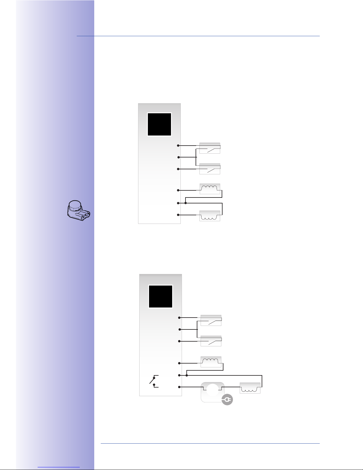
98/148
T24 System Manual Part 1: Installation
© MOBOTIX AG • Security-Vision-Systems • Made in Germany
www.mobotix.com • [email protected]
2.5.2 Connection Diagrams For Door Opener Versions
Version 1: Power Supply From T24-DoorMaster Battery (Self-Powered)
The T24-DoorMaster's permanently-charged battery pack provides a supply voltage to
the door opener and therefore also bridges power failures.
Version 2: Power Supply From External Power Supply Unit (Internal Relay Function)
The T24-DoorMaster's integrated relay function switches a maximum external voltage of
24 V (SELV, max. 1 A).
b2$ +5$ $'1<"2$;
+5#$$?-&#$ 1"''$1+"#
("# +$#) '*<2 +5*+
*#$ *22&@'$; +-" - #$2
PKT?RMb8?Q P '2$#+
3'2+#&>>$; - #$2
*'; >#$22 ;"-'
13++&'@ 1<*)>
-&+5 >< $#2Q
D$<(?>"-$#$;
P2+*';*#; 7$#2&"'Q
T24-DoorMaster
IN 1+
IN -
IN 2+
OUT 1+
OUT -
OUT 2+
Door contact
Door lock switch
Anti-theft protection
Door opener
85$ 89:?C""#!*2+$#
5*2 *' &'+$@#*+$;
#$<*4 (3'1+&"'
T24-DoorMaster
IN 1+
IN -
IN 2+
OUT 1+
OUT -
OUT 2+
Door contact
Door lock switch
Door opener
24 V AC
(SELV)
+ -
Power supply
Anti-theft protection
Page 99
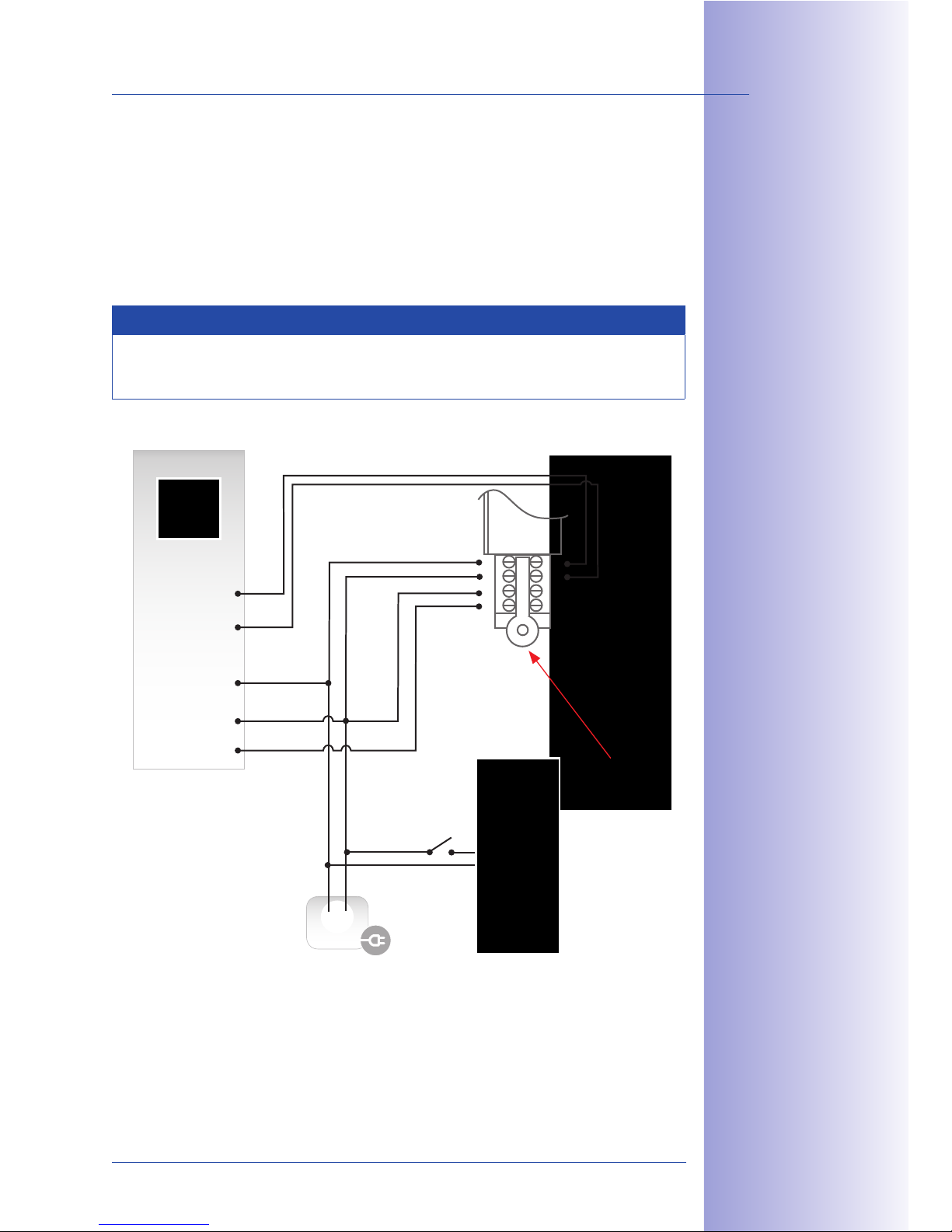
99/148
Installing The T24-DoorMaster
© MOBOTIX AG • Security-Vision-Systems • Made in Germany
www.mobotix.com • [email protected]
Version 3: Self-Locking Mediator Door Lock Including UPS Via Battery Pack
In this connection option, the T24-DoorMaster's battery pack powers the system in the event
of a power failure and allows the door to be opened without a key. In this case however,
anti-theft protection must be controlled using an additional switch (to be ordered separately).
In the following diagram, for example, anti-theft protection is used together with a Mediator
power supply. The modules can then be released by pressing the switch.
Note
The anti-theft protection must be disconnected from the voltage again after no longer
than five minutes (in the example switch ‘S’ is o) in order to avoid an overload.
!$;&*+"#
a'+&?+5$(+ >#"+$1+&"'
1"''$1+&"' 1*/<$2
*#$ >#$?]++$; +" +5$
(#*)$ *'; 1*' /$
$0+$';$; P)*0. cG )Q
1
2
3
4
8
7
6
5
T24-DoorMaster
IN 1+
IN -
IN 2+
OUT 1+
OUT -
OUT 2+
Original Mediator
Power supply
+ -
Mediator
Anti-theft protection
Door station
S
12 V DC
(SELV)
Page 100
100/148
T24 System Manual Part 1: Installation
© MOBOTIX AG • Security-Vision-Systems • Made in Germany
www.mobotix.com • [email protected]
2.5.3 Mounting Instructions
Solid Concrete Or Stone Wall
MOBOTIX recommends using a deep in-wall socket (more space for cables). Standard
in-wall sockets with a depth of 43 mm are not suitable for the T24-DoorMaster.
Cavity Wall (e.g. Plasterboard, 7 mm to 35 mm)
Use the supplied 61 mm-deep cavity socket for the T24-DoorMaster.
Note
MOBOTIX oers two orange cavity sockets of dierent depths (48 mm and 61 mm).
The 61 mm-deep socket is designed for the T24-DoorMaster, and the 48 mm-deep
socket is intended for the T24-Info2wire+ indoor unit.
Determining The Installation Position
The T24-DoorMaster must always be installed indoors protected from weather and moisture.
If in doubt, use the normal installation conditions of a standard socket with no cover as a
guide. The anti-theft protection connection cables pre-fitted to the frame of the outdoor
station do not need to be extended if the T24-DoorMaster is mounted on the same wall
behind the outdoor station (next to the entrance door).
C#&<< 5"<$ ("# 1*7&+4
2"16$+, g JF ))
Cavity socket (ø 68 mm, 61 mm in depth)
!*0&)3) !0N32
1*/<$ <$'@+5 /$+-$$'
89:?C""#!*2+$# *';
;""# 2+*+&"', cG )
Deep in-wall socket (ø 68 mm, 67 mm in depth)
 Loading...