

Page 1
SpeedDome
MOBOTIX MOVE SD-330
Quick Install
Page 2
SpeedDome SD-330
3 AC24V N
This guide is for quick installing and connecting the MOBOTIX MOVE SD-330 Network PTZ Camera. You can find
detailed information on the installation and connections in the Camera Manual (PDF, available on www.mobotix.com >
Support > Download Center > Documentation > Manuals).
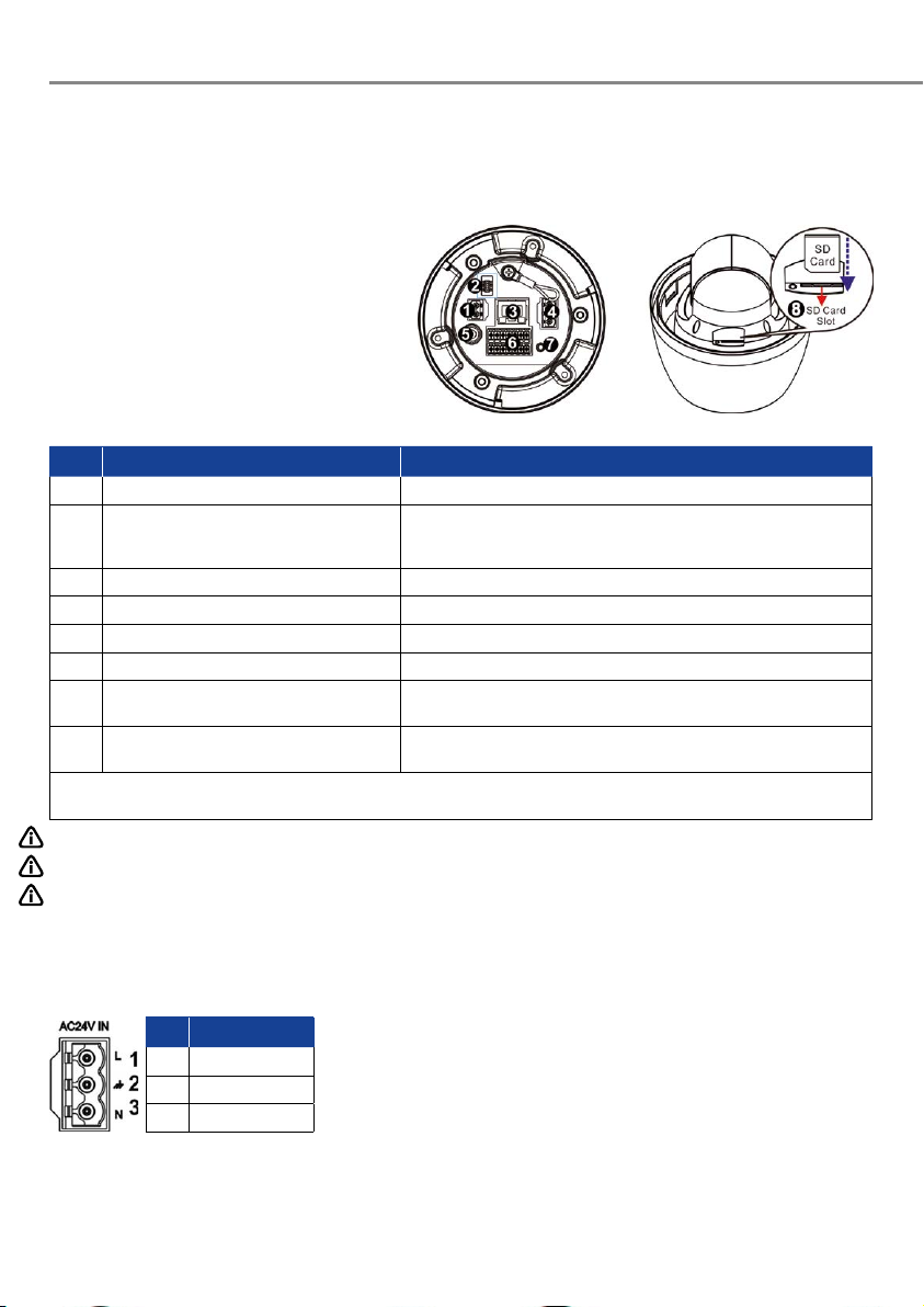
Camera’s Connectors
No. Connector Definition
1 Power Connector (DC12V) DC12V power connection
2 Console Connector This connector is used to burn firmware into the camera when the
3 RJ-45 Port For network and PoE+ connections
4 Power Connector (AC24V) AC24V power connection
5 BNC* For analog video output (available only with max. 2 activated streams)
6 Audio/Alarm I/O & RS485 Connector** Audio/Alarm I/O & RS485 connection
7 Reset Button Press the button with a proper tool for at least 20 seconds to restore the
8 SD Card Slot Insert the SD card into the card slot to store videos and snapshots. Do
*Please contact the manufacturer for the compatible BNC cable.
**Do NOT connect external power supply to the alarm I/O connector of the camera.
camera is returned for repair/maintenance. Please contact the camera
manufacturer for further information.
system.
not remove the SD card when the camera is powered on.
NOTE: To purchase power adaptor, please contact the camera manufacturer for further information.
NOTE: DC12V power jack and AC24V power connector cannot be used at the same time in case of unexpected damage.
NOTE: It is not recommended to record with the SD card for 24/7 continuously, as it may not be able to support long
term continuous data read/write. Please contact the manufacturer of the SD card for information regarding
the reliability and the life expectancy.
Power Connection
Pin Definition
1 AC24V L
2 GND
To power up the camera, connect the DC12V or AC24V power adaptor to the
power connector of the camera and the power outlet. Refer to the diagram
and pin definition below for AC24V power connection.
Alternatively, users can use an Ethernet cable and connect it to the RJ-45
port of the camera and a PoE+ switch (Class 4).
Page 3
Zero Downtime Power Switching (ZDT)
When users connect DC12V power jack and the RJ-45 port at the same time, the power input comes from the DC12V
connector. If the DC12V power source fails, the camera will switch power input seamlessly to the RJ-45 port until
the DC12V power source is restored.
Ethernet Cable Connection
Connect one end of the Ethernet cable to the RJ-45 connector of the camera, and plug the other end of the cable
to the network switch or PC.
NOTE: In some cases, Ethernet crossover cable might be needed when connecting the camera directly to the PC.
NOTE: Check the status of the link indicator and activity indicator LEDs. If the LEDs are unlit, please check the
LAN connection.
Green Link Light indicates good network connection.Orange Activity Light flashes for network
activity indication.
NOTE: The ITE is to be connected only to PoE networks without oute plant or equivalent description.
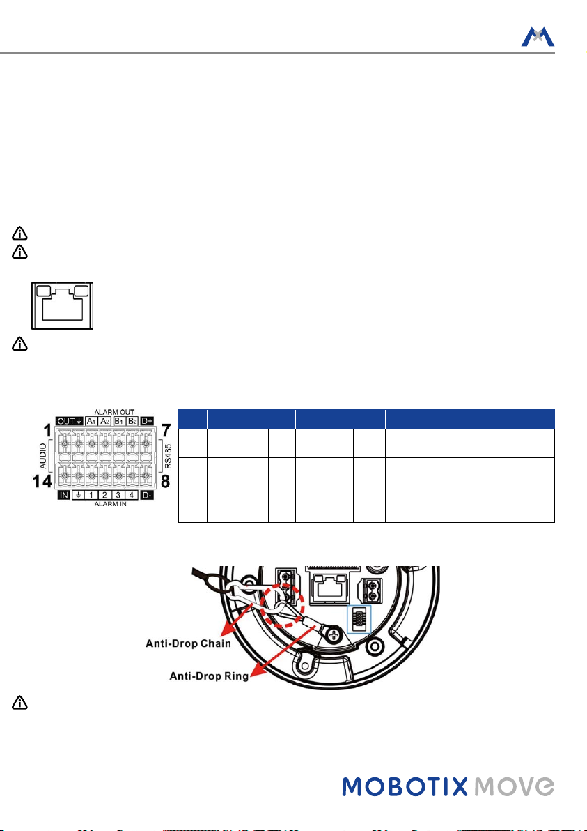
Audio/AIarm I/O & RS485 Connection
Please refer to the diagram and pin definition tables below for audio/alarm I/O & RS485 connection.
Pin Definition Pin Definition Pin Definition Pin Definition
1 Audio Out 5 Alarm Out B19 Alarm In 4 13 GND (Alarm I/O
2 GND (Audio
I/O)
3 Alarm Out A1 7 RS485 D+ 11 Alarm In 2
4 Alarm Out A2 8 RS485 D- 12 Alarm In 1
6 Alarm Out B210 Alarm In 3 14 Audio In
and RS485)
Camera Installation Notice
NOTE: For safety concern, it is recommended to hook up the camera with the anti-drop chain of the pendant
when installing the camera. For more information about pendant and anti-drop chain, please contact the
camera manufacturer.
Page 4
SpeedDome SD-330
Before Login to the Camera
A client program will be automatically installed to the PC when connecting to the camera. Before logging in to the
camera, please ensure downloading the ActiveX control is allowed by either changing the ActiveX controls and
plug-ins or setting Internet’s security level to default. For further details, please refer to the User’s Manual.
ActiveX Controls and Plug-ins Settings Internet Security Level
Step 1: Start the Internet Explorer (IE).
Step 2: Select <Tools> from the main menu of the browser.
Then click on <Internet Options>.
Step 3: Click on the <Security> tab and select <Internet>, and
click on <Custom level> to change ActiveX settings.
Step 4: Set “ActiveX controls and plug-ins” items to <Prompt>
or <Enable>.
NOTE: For the system requirement of the web browser, it is required to connect the camera with Microso Internet
Explorer 10.0 or later version to ensure smooth operation.
Camera Login
The default IP address of the camera is: 10.x.x.x. By default, the camera start s as a DHCP client and automatically tries to get an IP address from a DHCP ser ver.
Login ID & Password
Key in the camera’s IP address in the URL bar of the web browser window and hit “Enter”. Enter the default
username (admin) and password (meinsm) in the prompt request dialogue. The password must be changed
upon the first login.
Install the ActiveX Control
Aer connecting to the camera, the request for installing the ActiveX control will appear just below the URL
bar. Right click on the information bar and click on <Install ActiveX Control…> to permit ActiveX control installation. In the pop-up security warning window, click on <Install> to star t downloading DCViewer soware on
the PC. Click on <Finish> aer DCViewer installation is completed.
Step 1: Start the IE Internet Explorer (IE).
Step 2: Select <Tools> from the main menu of the browser.
Then click on <Internet Options>.
Step 3: Click on the <Security> tab and select <Internet>.
Step 4: Down the page, click on <Default Level> and <OK> to
confirm the setting. Close the browser window, and
open a new one later for accessing the IP camera.
EN_09/2020
MOBOTIX AG • Kaiserstrasse • D-67722 Langmeil • Tel.: +49 6302 9816-0 • Fax: +49 6302 9816-190 • [email protected] • www.mobotix.com
MOBOTIX, the MX Logo, MxControlCenter, MxEasy, MxPEG and MxActivitySensor are trademarks of MOBOTIX AG registered in the European Union, the U.S.A.
and in other countries • For a complete product overview and a current price list, see the MOBOTIX website • Sold only to distributors or commercial clients •
Subject to change without notice • MOBOTIX do not assume any liability for technical or editorial errors or omissions contained herein • All rights reserved •
© MOBOTIX AG, 2018
 Loading...