

Page 1
Camera Manual
S16 DualFlex
20.100.096-01_DE_07/2019
Page 2

S16 Camera Manual
Copyright © 1999-2019, MOBOTIX AG, Langmeil, Germany. Technical information subject
MOBOTIX Seminars
MOBOTIX o ers inexpensive seminars that include workshops and practical exercises.
For more information, visit www.mobotix.com > Support > Trainings.
THE MOBOTIX INFORMATION CHANNELS
Support on the MOBOTIX Website
www.mobotix.com/en/support
The MOBOTIX Video Tutorials
www.mobotix.com/en/support/
download-center/documentation/video-tutorials
Seminars on MOBOTIX Campus
www.mobotix.com/en/support/
trainings
The MOBOTIX YouTube Channel
www.youtube.com/user/MobotixAG
Copyright Information
All rights reserved.
trademarks of MOBOTIX AG registered in the European Union, the U.S.A., and other
countries.
Corporation.
the Bonjour icon,
and other countries.
Linux
are trademarks or registered trademarks of the respective owners.
to change without notice. MOBOTIX AG and its subsidiaries do not assume any liability
for technical or editorial errors or omissions contained herein.
Download the latest version of this and other manuals as PDF les from
www.mobotix.com > Support > Download Center > Documentation > Manuals.
Microso , Windows
is a trademark of Linus Torvalds. All other marks and names mentioned herein
MOBOTIX
Apple
, the Apple logo,
iPod
and
iPhone, iPad, iPad mini
, the MX logo,
and
Windows Server
MxManagementCenter
Macintosh, OS X, iOS, Bonjour
iTunes
are trademarks of Apple Inc. registered in the U.S.A.
and
2
and
MxPEG
are
are registered trademarks of Microso
, the Bonjour logo,
iPod touch
are Apple Inc. trademarks.
Page 3

Table of Contents
TABLE OF CONTENTS
Safety Warnings 6
Legal Notes 6
Notes on System Security (“Cyber Security”) 7
Foreword 8
1 Product Overview 10
1.1 S16 – Lenses, Hardware, Image Formats 10
1.2 S16–SowareFeatures 11
1.3 S16 – Technical Data 12
1.3.1 Technical Specications Thermal/Thermal-TR Sensor Modules 14
1.3.2 Technical Specications S16 With Thermal/Thermal-TR Sensor Modules 14
1.4 Delivered Parts and Dimensions 16
1.4.1 The S16 Body 16
1.4.2 Sensor Modules Mx-O-SMA-S-6D/L/N016 22
1.4.3 Sensor Modules Mx-O-SMA-S-6D/L/N036/041/061/079/119/237 24
1.4.4 Sensor Modules Mx-O-SMA-S-6D/L/N500 26
1.4.5 BlockFlexMounts Mx-O-SMA-B-6D/L/N016/036/041/061/079/119/237/500 28
1.4.6 BlockFlexMount Mx-O-SMA-B-6D/L/NCS (CS-Mount) 30
1.4.7 Sensor Module Thermal Mx-O-SMA-TS-T/R079/119/237 32
1.5 Available Accessories 34
1.5.1 DualMount 34
1.5.2 SurroundMount 34
1.5.3 HaloMount 34
1.5.4 SpeakerMount 35
1.5.5 PTMount 35
1.5.6 PTMount-Thermal(-TR) 35
1.5.7 Extension for Sensor Module 36
1.5.8 Ceiling/Wall Installation Set 36
1.5.9 Connection Cable for Sensor Module 36
1.5.10 MiniUSB Cable to MiniUSB (Straight/Straight or Straight/Angled) 36
1.5.11 MiniUSB Cable to USB a Socket 37
1.5.12 Ethernet Patch Cable for Bayonet Catch 37
1.5.13 NPA-PoE-Set 37
1.5.14 MX-Overvoltage-Protection-Box 38
1.5.15 MX-NPA-Box 38
1.5.16 MX-GPS-Box 38
1.5.17 MX-232-IO-Box 39
1.5.18 ExtIO Expansion Module 39
1.5.19 Mx2wire+ Media Converter 39
3
Page 4

Table of Contents
1.5.20 Other Accessories 40
1.6 MOBOTIXSoware 41
1.6.1 Integrated Camera Soware (Firmware) 41
1.6.2 MxManagementCenter 42
1.6.3 MOBOTIX MxBell 43
2 Installation 44
2.1 Preparing the Installation 44
2.1.1 Positioning a Hemispheric Camera 45
2.1.2 S16 FlexMount Installation Options 50
2.2 Before Mounting 57
2.2.1 Overview of Cable Connections 57
2.2.2 Notes on Cable Lengths and Power Supply 59
2.2.3 Network Connection with MOBOTIX Patch Cable 60
2.2.4 Network Connection with Installation Cable 61
2.2.5 Using Sensor Modules (S16 Only) 61
2.2.6 Using the MiniUSB Cable 61
2.2.7 Using MxBus Modules 62
2.2.8 External Audio Support (Microphone/Speaker) 62
2.2.9 Replacing the MicroSD Card 63
2.2.10 Tools Required for Installation 63
2.2.11 Preparatory Steps 64
2.3 Installing the S16 FlexMount 65
2.3.1 Attaching the S16 Body 65
2.3.2 Attaching and Connecting the S16 Sensor Modules 66
2.3.3 Plugging in and Removing Extensions 67
2.4 Network and Power Connection, Additional Cables 69
2.4.1 Network Cabling for S16 with Patch Cables 69
2.4.2 Network Cabling for S16 with Installation Cables 70
2.4.3 Connecting Additional Cables 72
2.4.4 Power Supply Using a Switch 73
2.4.5 Power Supply When Connected Directly to a Computer 74
2.4.6 Power Supply with Power-Over-Ethernet Products 74
2.4.7 Variable PoE 75
3 Operating the Camera 76
3.1 Manual and Automatic Operation 76
3.2 First Images and the Most Important Settings 78
3.2.1 Manually Setting Up the Network Parameters in a Browser 78
3.2.2 First Images and the Most Important Settings in the Browser 81
3.2.3 First Images and Network Parameter Conguration in MxMC 83
3.2.4 Start Options of the Camera 86
44
Page 5

Table of Contents
3.3 Adjusting Lens Focus and Inserting a Filter 88
3.3.1 Adjusting Lens Focus (L65-L76/L135-L160 Only) 88
3.3.2 Inserting a Filter 89
3.3.3 Replacing the Dome Against the Sealing Ring (Only Sensor Modules L10-L12) 90
3.4 Virtual PTZ and Full Image Recording 92
3.4.1 Preparing the Virtual PTZ Function 92
3.4.2 Full Image Recording 94
3.4.3 Special S16 Conguration in the Browser 96
3.5 MicroSD Card Recording 106
3.5.1 Introduction 106
3.5.2 Formatting the MicroSD Card 108
3.5.3 Activating Recording 109
3.5.4 Accessing Data on the MicroSD Card 110
3.5.5 Deactivating Card Recording 110
3.5.6 Using a MicroSD Card in a Dierent MOBOTIX Camera 111
3.5.7 Limitations on Warranty When Using Flash Storage Media 111
3.6 CongurationintheBrowser 112
3.6.1 Overview 112
3.6.2 General Browser Settings 113
3.6.3 Conguring the S16 with Thermal(-TR) Sensor Modules in the Browser 115
3.7 Setting Up an S16 FlexMount as Door Station 117
3.7.1 Installation 117
3.7.2 Execute Auto Conguration 118
3.8 Additional Notes 119
3.8.1 Do Not Sharply Bend the Connection Cables to the Sensor Modules 119
3.8.2 Reduced Weather Protection When Installing Upside-Down 119
3.8.3 Password for the Admin Menu 119
3.8.4 Permanently Deactivating the Microphone 120
3.8.5 Using the Start Options of the Camera 120
3.8.6 Activating Event Control and Motion Detection 120
3.8.7 Deactivating Text and Logo Options 121
3.8.8 Deactivating the Camera Reboot 121
3.8.9 Browser 121
3.8.10 Cleaning the Camera and Lens 121
3.8.11 Online Help in the Browser 122
3.8.12 Declaration of Conformity 122
3.8.13 RoHS Declaration 122
3.8.14 Disposal 122
3.8.15 Disclaimer 123
5
Page 6
Table of Contents
§
SAFETY WARNINGS
Notes on Installing:
• This product must not be used in locations exposed to the dangers of explosion.
• Make sure that you install this product as outlined in Chapter 2, «Installation» of this
• When installing this product, make sure that you are only using genuine MOBOTIX
•
Electrical installation: Electrical systems and equipment may only be installed, modied
and maintained by a qualied electrician or under the direction and supervision of a qual
ied electrician in accordance with the applicable electrical guidelines. Make sure to properly set up all electrical connections.
Electrical surges: MOBOTIX cameras are protected against the eects of small electrical
surges by numerous measures. These measures, however, cannot prevent the camera from
being damaged when stronger electrical surges occur. Special care should be taken when
installing the camera outside of buildings to ensure proper protection against lightning,
since this also protects the building and the whole network infrastructure.
Max. power consumption of attached extension modules: The power consumption of all
attached
connector
not exceed 4 W
era cannot power any peripheral devices!
manual. A faulty installation can damage the camera!
parts and MOBOTIX connection cables.
Only install this product on suitable, solid materials that provide for a sturdy installation
of the xing elements used.
MxBus modules
and
the USB socket, the
,
if the camera is powered by PoE class 3
must
not exceed 3 W
. When attaching modules to the MxBus
power consumption of all attached modules must
. If
PoE class 2
is used,
the cam-
-
Never touch the lens: Due to the high performance of the S16, the area of the image sensor
can get quite hot, especially when the ambient temperature is also high. This does not aect
the proper functioning of the camera in any way. For this reason, the product must not be
installed within the reach of persons.
Powerobeforeopeningthecamera: Make sure the power supply to the camera is dis
connected before opening the camera housing (e.g., when inserting or exchanging lenses,
lens units and SD cards).
-
LEGAL NOTES
Legal aspects of video and sound recording
You must comply with all data protection regulations for video and sound monitoring when
using MOBOTIX products. Depending on national laws and the installation location of the
S16, the recording of video and sound data may be subject to special documentation or
it may be prohibited. All users of MOBOTIX products are therefore required to familiarize
themselves with all applicable regulations and to comply with these laws. MOBOTIX AG is
not liable for any illegal use of its products.
66
Page 7
§
Attention – Special Export Laws Apply!
Cameras with thermal image sensors (“thermal cameras”) are subject to the special export
regulations of the U.S.A. and the ITAR (International Traic in Arms Regulation):
• Under the United States sanctions and export regulations currently in force, cameras
with thermal screen sensors or parts thereof may not be delivered, in particular, to
countries or regions to which the U.S.A. have imposed an embargo, unless a spe
cial exemption permit is available. At present, this applies to the following countries or regions: Syria, Iran, Cuba, North Korea, Sudan and Krim. The same export
ban applies to all persons and institutions listed in “The Denied Persons List” (see
www.bis.doc.gov > Policy Guidance > Lists of Parties of Concern; https://
www.treasury.gov/resource-center/sanctions/sdn-list/pages/
default.aspx).
• Under no circumstances must the camera itself or its thermal image sensors be used
in the design, the development or in the production of nuclear, biological or chemical
weapons or in the weapons themselves.
NOTES ON SYSTEM SECURITY (“CYBER SECURITY”)
To protect the camera against security risks in data technology, the following measures are
recommended aer the installation has been completed:
• MxManagementCenter:
– Menu View > Wizards & Tools > Secure System:
• Change camera factory default password: √
• Enable encrypted HTTPS: √
• Disable public access: √
– User Management (for all users):
• Force Complex Password: √
• Logout on Inactivity: Aer 5 min
• User interface of the camera in the browser:
– Admin Menu > Network Setup > Web Server:
• Enable MxWeb: –
• Enable intrusion detection: √
• Notication threshold: 10
• Timeout: 60 Minutes
• Block IP Address: √
For more information on this topic, please read the «Cyber Protection Guide» on
www.mobotix.com (under Support > Download Center > Documentation > Brochures
& Guides > Cyber Security).
-
7
Page 8
S16 Camera Manual
FOREWORD
Dear MOBOTIX customer,
Congratulations on your decision to purchase a professional and modern HiRes network
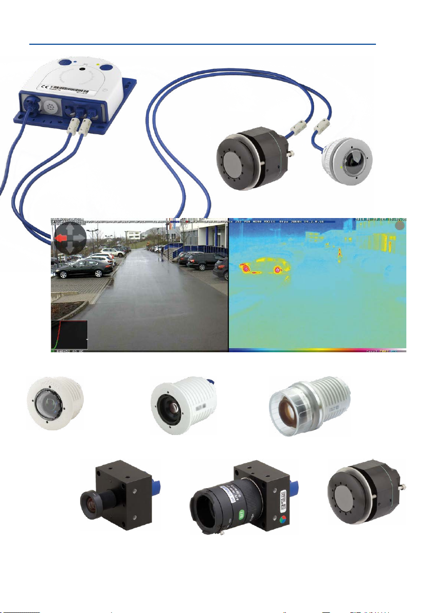
camera “Made in Germany”! The robust and versatile S16 can be placed discreetly and
securely behind walls and ceilings or stainless steel panels with only the sensor modules
visible from the room. The sensor modules are available with dierent focal lengths; from
device. The additional mounting options (DualMount, SurroundMount, HaloMount, PTMount)
provide the highest exibility when installing the modules.
The introduction of the newest 6MP image sensor technology with increased light sensitivity
provides brilliant images with image sizes of up to 3072x2048 pixels, thus delivering color
images of higher quality under lowlight conditions.
The Thermal sensor modules supplement the proven MOBOTIX technology by a high-end
thermal imaging sensor, which can reliably detect moving objects even in total darkness. The
Sensor Module Thermal-TR (TR = Thermal Radiometry
temperatures in the image or in measurement windows that exceed or drop below the
specied temperature.
The weatherproof MxBus and MiniUSB interfaces of the camera allow attaching MOBOTIX
interface boxes and standard devices, such as 3G/UMTS modems, external storage devices,
etc. The pre-installed MicroSD card ash storage is easily exchanged for larger storage requirements, providing for secure long-term storage.
tele to hemispheric lenses, as day, night or LPF variants in black or white. If a speaker
is required, why not use the SpeakerMount for easy installation into ceilings or
walls?
The BlockFlexMounts represent the same sensor modules in a dierent housing
that has been designed especially for integration into any given structure or
) can trigger alarms when detecting
You can download the MxManagementCenter video management soware for MOBOTIX
cameras from the MOBOTIX website: www.mobotix.com > Support > Download Center >
SowareDownloads. The tutorial for the application is available from Support > Download
Center > Documentation > Brochures & Guides > Tutorials.
For iPad, iPhone, and Android devices, MOBOTIX oers the MOBOTIX MxBell, a free-of-charge
mobile solution that is easily found when searching for “MOBOTIX AG” in the App Store or
on Google Play.
If you have any questions, our support and international sales sta are available at
intl-support@mobotix.com
We would like to thank you for your trust and wish you all the best with your new MOBOTIX
camera S16 DualFlex!
from Monday to Friday, 8 am to 6 pm (German time).
8
Page 9
Sensor module
B016
BlockFlexMount
B016 to B500
Sensor module
B036 to B237
BlockFlexMount
CS-Mount (without lens)
Sensor module
B500
Sensor Module Thermal (-TR)
MX-SM-TR079/119/237
9
Page 10
S16 Camera Manual: Product Overview
1 PRODUCT OVERVIEW
1.1 S16 – Lenses, Hardware, Image Formats
Objektive, Sensoren
MX-B016 Hemispheric •
MX-B036 Super Wide-Angle •
MX-B041 Super Wide-Angle •
MX-B061 Wide-Angle •
MX-B079 Wide-Angle •
MX-B119 Tele •
MX-B237 Tele •
MX-B500 Tele •
CSVario 4.5 bis 10 mm •
Thermal(-TR)079/119/237 •/•/•
Image sensor with custom exposure zones Color/BW (freely combinable)
Sensor sensitivity in lux at 1/60 s and 1 s
Hardware Features
IP protection class IP66
Temp. Internal DVR (MB) 64
Internal DVR (MicroSD, SDXC, pre-installed) •
Microphone (in sensor modules)/speaker •/–
Passive infrared sensor (PIR) – (via MxMultiSense MxBus module)
Integrated temperature sensor •
Shock detector •
Power consumption in watts (typical) < 7,5 W
Variable PoE class 2 – 3 (with Thermal sensor module: 3)
Image Formats, Frame Rates and Image Storage
Max. resolution (per sensor) 6MP (3072x2048)
Max. frame rate (MxPEG, max. resolution) 6MP: 12 fps
CIF images with 4 GB MicroSD DVR 250,000
VGA images with 4 GB MicroSD DVR 125,000
MEGA images with 4 GB MicroSD DVR 40,000
QXGA images with 4 GB MicroSD DVR 20,000
0,1 / 0,005 (Color)
0,02 / 0,001 (BW)
10
Page 11
S16 – Soware Features
1.2 S16–SowareFeatures
General Features
Digital zoom (continuous) with panning •
Motion JPEG/MxPEG codecs •/•/•
Programmable exposure zones • (with Thermal sensor module)
Alarms when exceeding/dropping below spec. temperature Thermal sensor module only
Snapshot rec. (pre-/post-alarm images) 50
Terabyte ring buer storage (internal/network) •
Event/continuous rec. with sound (0.2 to 30 fps) •/•
Time and event control •
Weekly schedules/holidays •
Web functionality (FTP, email) •
Playback/Quad and MultiView, bidirectional sound in
browser
Logo generator, animated •
Flexible event logic •
Master/Slave arming •
Several scheduled privacy zones •
Customized voice messages •
VoIP telephony (audio/video, alert) •
Remote alarm notication (network msg.) •
Signal inputs/outputs, RS232
Programming interface/HTTP API •
Security features (HTTPS/SSL, IP-based access control, IEEE
802.1X network authentication)
Video Analysis
Video Motion detector •
MxAnalytics •
MxActivitySensor •
VideoManagementSoware
MxManagementCenter •
MOBOTIX MxBell •
•
Via MX-Input-Box/MX-Output-Box or
MX-232-IO-Box
•
Free-of-charge download
from www.mobotix.com
or App Store/Google Play
11
Page 12

S16 Camera Manual: Product Overview
1.3 S16 – Technical Data
Mx-S16A/B* (all combinations of day/night/Low-Pass-Filter/Thermal/
Model Variants
Lens Option MX-B016 to MX-B500, horizontal image angles 180° to 8°
Sensitivity
Image Sensor 1/1.8” CMOS, 6MP (3072x2048), Progressive Scan
Max. Image Size 6MP (3072x2048)
Image Formats
Max. Frame Rate
Video Codec
ONVIF ONVIF-S (camera soware V5.2.x and higher)
DVR
External Video Ring
Buer
Soware MxManagementCenter, MOBOTIX MxBell
Image Processing
PTZ Digital pan/tilt/zoom, continuous up to 8X
Alarm/Events
Intelligent Video
Analysis
Audio
Interfaces
Security
Thermal-TR sensor modules)
*Variant Mx-S16B supports MOBOTIX MxBus modules
Color sensor (daylight): 0,1 lx @ 1/60s; 0,005 lx @ 1s
Black&White sensor (night): 0,02 lx @ 1/60s; 0,001 lx @ 1s
Freely congurable 4:3, 8:3, 16:9 or custom formats (image cropping), e.g.,
2592x1944 (5MP), 2048x1536 (QXGA), 1920x1080 (Full-HD), 1280x960 (MEGA)
MxPEG: 42@HD(1280x720), 34@Full-HD, 24@QXGA, 15@5Mp, 12@6MP
M-JPEG: 26@HD(1280x720), 13@Full-HD, 9@QXGA, 5@5Mp, 4@6MP
H.264: 25@Full-HD, 20@QXGA
MxPEG, M-JPEG, JPEG (max. output size 6MP)
H.264 (max. output size QXGA, bandwidth limitation applicable)
In the camera on MicroSD card (SDXC, SDHC pre-installed)
• External, on USB device
• External, on NAS
• Separate live image and full image recording – MxFFS with archiving
function
• Pre- and post-alarm images
• Automatic DVR monitoring with error notication
Directly on NAS and computer/server without additional recording soware
MxLEO, backlight compensation, automatic white balance, distortion cor
rection
Temperature sensor, shock detector (with rmware version 5.0.1 and higher),
microphone, additional sensors/IOs via MxMessageSystem, notication via
e-mail, FTP, IP telephony (VoIP, SIP), visual/sound alarms, pre- and postalarm images
MxActivitySensor, video motion analysis, MxAnalytics
External microphone and speaker can be connected 16 bit/16 kHz (HD wide
band audio); lip-synchronous audio, audio recording; VoIP/SIP telephony,
intercom, remote controlling using key codes
10/100 Ethernet (patch or installation cable), MiniUSB, MxBus*;
inputs/outputs and RS232 via accessories; external microphone, external
speaker
*Only variant Mx-S16B
User/group management, HTTPS/SSL, IP address lter, IEEE 802.1x, intrusion
detection, digital image signature, MxFFS
-
-
12
Page 13
S16 – Technical Data
EN 55032:2012, EN 55024:2010, EN 50121-4:2015, FprEN 61000-6-1:2015,
Certications
Power Supply Power over Ethernet IEEE 802.3af
Power Consumption Typ. 7,5 W
Power Consumption of
External Devices
Protection Classes
Ambient Temperature –40 to 60 °C/–40 to 140 °F
Dimensions/Weight
S16
Dimensions/Weights
Sensor Modules
Standard Delivery
EN 61000-6-2:2015, EN 61000-6-3:2007+A1:2011+AC:2012, EN 61000-64:2007+A1:2011, EN 50581:2012, EN 60950-1:2006+A11:2009+A1:2010+A12:20
11+A2:2013, E13*10R05/01*14649*00, 47 CFR Part 15B, AS/NZS CISPR32:2015
At MxBus: max. 3 W, at USB: max. 2.5 W, total max. 4 W
The power consumption of the camera will increase accordingly!
IP66
IK07
W x H x D: 115 x 130 x 33 mm; weight: approx. 430 g/0.948 lb (without sensor
modules, see below)
Mx-O-SMA-S-6016: Ø x T: 43 x 45 mm (installation dim.), weight 85 g
Mx-O-SMA-S-6D/N036/041/079: Ø x T: 43 x 57 mm (installation dim.), wt. 111 g
Mx-O-SMA-S-6D/N061/119/237: Ø x T: 43 x 60 mm (installation dim.), wt. 122 g
Mx-O-SMA-S-6D/N500: Ø x T: 43 x 60 mm (installation dim.), weight 160 g
Housing (high-resistance composite, PBT), white, blue anodized aluminum
base plate, mounting parts, Allen wrench, 50 cm patch cable, manual, so
ware, MicroSD card (SDXC, SDHC pre-installed)
-
13
Page 14

S16 Camera Manual: Product Overview
1.3.1 TechnicalSpecicationsThermal/Thermal-TRSensorModules
Lens Options
Sensitivity NETD typ. 50 mK (equals 0.05°C), <79 mK
Image Sensor Uncooled microbolometer, 336x252 pixels, spectral range 7.5 to 13.5 μm
Temperature
Measurement Range
Max. Image Size
Max. Frame Rate
SowareFeatures
Power Consumption Typ. 1.5 W per S16
Operating Conditions
Dimensions Total length: 78 mm, max. Ø: 63 mm
Materials
Weight < 330 g (one S16 without sensor cable)
Sensor Module Thermal: L43 (45°), L65 (25°), L135 (17°)
Sensor Module Thermal-TR: TR079 (45°), TR119 (25°), TR237 (17°)
(horizontal angle of view)
–40 to +550 °C/–40 to 1,022 °F (temperature of the displayable objects)
precision of Sensor Module Thermal-TR: ±10 K of the thermal radiation
measured at the sensor
Can be scaled up to 3072x2048 (6MP), dual images are automatically scaled
to size of the optical sensor module
9 fps (when displaying an optical sensor module and a thermal sensor mod
ule, the overall frame rate of the camera is reduced to 9 fps)
O-color/black & white image display, mirrored image, obscured image
areas, vPTZ (virtual pan/tilt/zoom), text and logo display, display of event/
action symbols, meter display (bar chart or diagram), temperature control
windows
IP66 (DIN EN 60529)
–40 to 60 °C/–40 to 140 °F (DIN EN 50155)
Module housing: Aluminum, black anodized;
Pressure plate: Stainless steel V2A
1.3.2 TechnicalSpecicationsS16WithThermal/Thermal-TRSensorModules
Image Formats
(per sensor)
Alarm/Events
Operating Conditions
Power Consumption
Max. Power
Consumption of
Attached Extension
Modules
Power Supply
Standard formats like Full HD, VGA, etc. up to 3072x2048 (5MP) and custom
formats
Video Motion detection, MxActivitySensor, external signals, shock detector,
notication via e-mail, FTP, pre- and post-alarm images
IP65 (DIN EN 60529)
–40 to 60 °C/–40 to 140 °F (DIN EN 50155)
Depending on sensor modules used:
1 thermal, 1 optical: typ. 6.5 W (briey up to 7.5 W possible)
2 thermal: typ. 7 W (briey up to 8 W possible)
1 thermal: typ. 5.5 W (briey up to 6.5 W possible)
USB only: ≤ 1 W
MxBus only: ≤ 1 W
USB and MxBus: ≤ 2 W
Power-over-Ethernet (IEEE 802.3af);
PoE Class 3 required
-
14
Page 15
S16 – Technical Data
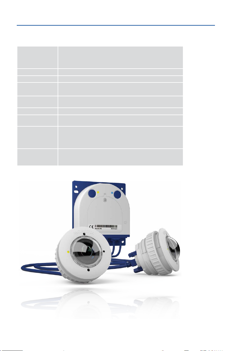
MOBOTIXS16With2xMx-O-SMA-TS-T/R079/119/237
MOBOTIXS16With1xMx-O-SMA-TS-T/R079/119/237,1xMx-O-SMA-S-6D016
15
Page 16

S16 Camera Manual: Product Overview
1.1
1.4 Delivered Parts and Dimensions
1.4.1 The S16 Body
M.10
M.9
M.6
M.7
M.5
M.4
M.8
M.3
M.2
M.1
1.11
1.10
1.6
1.4
1.2
1.3
1.5
1.7
1.8
1.9
16
Page 17

Delivered Parts and Dimensions
Item Number Part Name
1.1 1 S16 Core (body with base plate)
1.2 1 Housing cover for S16 (installed)
1.3 1 Stainless steel at-head Allen screw M4x8 (installed)
1.4 1 Washer (installed)
1.5 3 Sealing plug, blue, small (sensor modules, USB, inserted)
1.6 1 Sealing plug, blue, large (Ethernet patch cable, installed)
1.7 1 Cable retainer with bayonet catch (Ethernet patch cable, installed)
1.8 1
1.9 1 MicroSD card pre-installed (SDXC)
1.10 1 Rotary plug, SD card, blue (installed)
1.11 1 Ethernet patch cable, 50 cm, with seal
Mounting Supplies
Item Number Part Name
M.1 4 Stainless steel washers, diam. 4.3 mm
M.2 4 6-mm screw anchors
M.3 4 Stainless steel wood screws 4x40 mm with PZ 2 driver bit
M.4 2 Cable plug, 5–7 mm, white (Ethernet installation cable)
M.5 1 Cable plug, 3–5 mm, white (Ethernet installation cable)
M.6 1 Allen wrench 2.5 mm
M.7 1 Lens wrench (lens, dome)
M.8 1 Module wrench (sensor module, glass/lter insert)
M.9 1
M.10 1 Screwdriver (screw clamps)
Single wire plug, white (Ethernet installation cable, microphone,
speaker, MxBus; installed)
Cable tie (Ethernet installation cable, microphone, speaker,
MxBus)
17
Page 18

S16 Camera Manual: Product Overview
S16 Camera Body
The body of the MOBOTIX S16 consists of a housing, a housing cover and a base plate for
attaching the camera.
LED default settings:
1 Power (on), Error (ashes)
2 Recording (ashes)
MicroSD card
LEDs
Base plate
Key
S16 housing cover
Pressure compen-
sation
Bayonet catch
Triple cable retainer
1 2
L
Externally-AccessibleConnectionsoftheS16
The MOBOTIX S16 provides the following external connections that can be accessed once
the cover plugs are removed:
Cables with straight plugs
can be used for the S16
on the camera only
18
Ethernet patch cable
MiniUSB
Sensor modules
For external connections shown above always use the corresponding MOBOTIX cables with seal:
• Ethernet patch cable: MX-OPT-CBL-LAN-1/2/5/10
• MiniUSB (straight/straight): MX-CBL-MU-STR-05/2/5
• MiniUSB (straight/angled): MX-CBL-MU-EN-STR-05/2/5
• MiniUSB to USB-A (straight to USB port): MX-CBL-MU-STR-AB-05/2/5
• Sensor modules: MX-FLEX-OPT-CBL-05/1/2/3
Page 19

Delivered Parts and Dimensions
Internally-AccessibleConnectionsontheS16
The MOBOTIX S16 provides the following internal connections that can be accessed once
the cover plugs and housing cover are removed:
LSA+ terminal
Ethernet Installation
cable
Screw terminals
MxBus, microphone,
speaker
MOBOTIX-RJ45or
MxBus, microphone,
speaker
Ethernet installation cable
or MxBus, microphone,
speaker
Before laying the Ethernet installation cable, remove the bayonet catch and replace the
Ethernet patch cable plug with either one of the additional plugs (M.4/5) or the single wire
plug (1.8), depending on the cable used.
Additional cables
(MxBus, sound)
MOBOTIX patch cable
Installation cable
19
Page 20

S16 Camera Manual: Product Overview
on www.mobotix.com,
Support > Download
Center > Documentation >
Drilling Templates
Always print or copy
drilling template in
their original size
Measurements of the S16Find the drilling templates
115 mm/4.53 in
100 mm/3.94 in
100 mm/3.94 in
110 mm/4.33 in
8.50 mm/0.33 in
13.50 mm/0.53 in
M6
130 mm/5.12 in
47.50 mm/1.87 in
Ø 5.50 mm/0.22 in
20
Page 21

Delivered Parts and Dimensions
33.50 mm/1.32 in
5 mm/
0.20 in
Attaching the Camera Body
Slots
M6 tap holes
21
Page 22

S16 Camera Manual: Product Overview
Sensor type letter
D: Day
L: Low-Pass Filter
N: Night
Sensor module
with status LEDs
and microphone
1.4.2 SensorModulesMx-O-SMA-S-6D/L/N016
2.1
2.6
2.5
2.4
2.2
2.3
22
Item Number Part Name
2.1 1 Sensor module with aixed washer
2.2 1 MOBOTIX lens L10-L12 (installed)
2.3 1 Dome (installed)
2.4 1 Cable retainer with bayonet catch (installed)
2.5 1 Sealing plug, blue, small (installed)
2.6 1 Nut (plastic)
Page 23

Delivered Parts and Dimensions
Diam. 43 mm/1.7 in
Front View
LEDs
Sensor module
housing
Microphone
Rear View
Markers for top
Sensor cable con-
nection
Sensor module
housingl
Pressure compen-
sation
1 2
Diam. 50 mm/2 in
Diam. 43 mm/1.7 in
LED default settings:
1 Power (on), Error (ashes)
2 Recording (ashes)
Diam. 50 mm/2 in
Top = top border of
image (North)
Side View
Sensor module
weight without lock ring: 85 g
weight with lock ring: 91 g
Extension
58 mm/2.3 in
30 mm/1.2 in
40 mm/1.6 in
15 mm/0.6 in
Diam. 43 mm/1.7 in
Diam. 43 mm/1.7 in
23
Page 24

S16 Camera Manual: Product Overview
Sensor type letter
D: Day
L: Low-Pass Filter
N: Night
Sensor module
with status LEDs
and microphone
1.4.3 SensorModulesMx-O-SMA-S-6D/L/N036/041/061/079/119/237
3.1
3.6
3.5
3.4
3.2
3.3
24
Item Number Part Name
3.1 1 Sensor module with aixed washer
3.2 1
3.3 1 Protective glass insert with coated glass (installed)
3.4 1 Cable retainer with bayonet catch (installed)
3.5 1 Sealing plug, blue, small (installed)
3.6 1 Nut (plastic)
MOBOTIX lens L20-L23/L22-L25/L32-L38/L43-L51/L65-L76/
L135-L160 (installed)
Page 25

Delivered Parts and Dimensions
Diam. 50 mm/2 in
Diam. 43 mm/1.7 in
48 mm/1.89 in
15 mm/0.6 in
Front View
LEDs
Sensor module
housing
Microphone
Rear View
Markers for top
1 2
LED default settings:
1 Power (on), Error (ashes)
2 Recording (ashes)
Diam. 50 mm/2 in
Sensor cable con-
nection
Sensor module
housing
Pressure compen-
sation
Side View
Sensor module
weight without lock ring: 122 g
weight with lock ring: 128 g
Extension
40 mm/1.6 in
Diam. 43 mm/1.7 in
Top = top border of
image (North)
Diam. 43 mm/1.7 in
Diam. 43 mm/1.7 in
25
Page 26

S16 Camera Manual: Product Overview
Sensor type letter
D: Day
L: Low-Pass Filter
N: Night
Sensor module
1.4.4 SensorModulesMx-O-SMA-S-6D/L/N500
4.1
4.6
4.5
4.4
4.2
4.3
26
Item Number Part Name
4.1 1 Sensor module with aixed washer
4.2 1 MOBOTIX lens L270-L320 (installed)
4.3 1 Protective lens cover (installed)
4.4 1 Cable retainer with bayonet catch (installed)
4.5 1 Sealing plug, blue, small (installed)
4.6 1 Nut (plastic)
Page 27

Delivered Parts and Dimensions
Diam. 50 mm/2 in
Diam. 43 mm/1.7 in
48 mm/1.89 in32 mm/1.26 in
15 mm/0.6 in
Front View
Protective lens cover
Sensor module
housing
Rear View
Markers for top
Diam. 50 mm/2 in
Sensor cable con-
nection
Sensor module
housing
Pressure compen-
sation
Side View
Sensor module
weight without lock ring: 122 g
weight with lock ring: 128 g
Extension
Top = top border of
image (North)
Diam. 43 mm/1.7 in
40 mm/1.6 in
Diam. 43 mm/1.7 in
Diam. 43 mm/1.7 in
27
Page 28

S16 Camera Manual: Product Overview
Sensor type letter
D: Day
L: Low-Pass Filter
N: Night
BlockFlexMount
with status LEDs
and microphone
1.4.5 BlockFlexMountsMx-O-SMA-B-6D/L/N016/036/041/061/079/119/237/500
5.1
5.4 5.2
5.3
Item Count Part Name
5.1 1 Housing MX-BFM-MX, black anodized
5.2 1 MOBOTIX lens L10 to L270 (6MP), L12 to L320 (5MP) (installed)
5.3 1 Cable lock with bayonet catch (installed)
5.4 1 Sealing plug blue, small (installed)
28
Page 29

Delivered Parts and Dimensions
Front View
Back View
Side View
4 holes 4.2 mm diam.
Status LEDs
Microphone
Arrows indicate
top
Connector for sensor
cable
Pressure vent
2 tap holes/side M4 x 5 mm
Lens
32 mm/1.26 in
32 mm/1.26 in
40 mm/1.57 in
40 mm/1.57 in
Top = upper image border (North direction)
40 mm/1.57 in
Measurements
dep. on Lens
Lens D L
23.5 mm/
0.93 in
22.0 mm/
0.87 in
22.0 mm/
0.87 in
22.0 mm/
0.87 in
20.0 mm/
0.79 in
22.0 mm/
0.87 in
22.3 mm/
0.88 in
27.0 mm/
1.06 in
13.0 mm/
0.51 in
17.0 mm/
0.67 in
17.0 mm/
0.67 in
18.2 mm/
0.72 in
11.7 mm/
0.46 in
17.5 mm/
0.69 in
17.8 mm/
0.70 in
42.5 mm/
1.67 in
B016
8 mmL
B036
B041
D
22 mm/0.87 in
B061
B079
25 mm/0.98 in
40 mm/1.57 in
B119
B237
B500
29
Page 30

S16 Camera Manual: Product Overview
Sensor type letter
D: Day
L: Low-Pass Filter
N: Night
BlockFlexMount
with microphone
1.4.6 BlockFlexMountMx-O-SMA-B-6D/L/NCS(CS-Mount)
6.1
ordered separately!
MX-B045-100-CS*lensneedstobe
6.4
6.3
Item Count Part Name
6.1 1 Housing MX-BFM-CS, black anodized
6.2 2 Spacer disc 0.25 mm thick
6.3 1 Cable lock with bayonet catch (installed)
6.4 1 Sealing plug blue, small (installed)
6.2
30
Page 31

Delivered Parts and Dimensions
Front View
Back View
Top View
4 holes 4.2 mm diam.
Microphone
Arrows indicate
Connector for sensor
Pressure vent
Lock screw (Allen
wrench 1.5 mm)
top
cable
32 mm/1.26 in
32 mm/1.26 in
40 mm/1.57 in
8 mm/0.31 in43.4 mm/1.71 in
40 mm/1.57 in
Top = upper image border (North direction)
40 mm/1.57 in
Dia. 34 mm/1.34 in
Lens (needs to be ordered
separately)
2 tap holes/side M4 x 5 mm
22 mm/0.87 in
22.5 mm/0.89 in
37.6 mm/1.48 in
31
Page 32

S16 Camera Manual: Product Overview
Sensor type letter
T: Thermal
R: Thermal Radiometry
Thermal sensor module
1.4.7 SensorModuleThermalMx-O-SMA-TS-T/R079/119/237
7.1
7.8
7.7
7.6
7.5
7.2
7.3
7.4
Item Count Part Name
7.1 1
7.2 1 Front plate aluminum, black anodized (installed)
7.3 1 Pressure plate Ø 63 mm, stainless steel (installed)
7.4 3 Cylinder head screws M4x50 mm, stainless steel (installed)
7.5 1 Cable lock , blue (installed)
7.6 1 Sealing plug blue, small (installed)
7.7 1 Allen wrench 3 mm
7.8 1 Special export regulations German/English
Housing Mx-O-SMA-TS--L43/65/135 or
MX-SM-TR079/119/237, black anodized
32
Page 33

Delivered Parts and Dimensions
78 mm/3.07 in
12.5 mm/0.49 in
17 mm/0.67 in
Front View
Pressure plate dia.
63 mm/2.48 in
(behind wall/faceplate)
Front plate dia.
57 mm/2.24 in
(visible)
Back View
Ø 63 mm/2.48 in
Ø 57 mm/2.44 in
Side View
3 cylinder head screws
Ø M4, length of thread
Arrows indicate
top
Connector for sensor
cable
Pressure vent
3 cylinder head
screws
Thickness 0 to
14 mm/0.55 in
M4x50 mm
Hole diameter
48 mm/1.89 in
4 mm/0.16 in
3.5 mm/0.14 in
Top = upper image border (North direction)
Dia. 60 mm/2.36 in
33
Page 34

S16 Camera Manual: Product Overview
1.5 Available Accessories
1.5.1 DualMount
Order no.: MX-OPT-FM-PW
The DualMount provides for installing two sensor modules
side-by-side with parallel lines of sight, making it the ideal
installation solution for the S16 in day/night settings (both
lenses are monitoring the same area). The DualMount is
quickly and easily installed, it can be used with all available
sensor modules and the lenses are tilted downwards by 25
degrees. In outdoor applications, this installation option
can be installed without drawing much attention (beneath
eaves, protruding construction elements, bridges, etc.).
1.5.2 SurroundMount
Order no.: MX-OPT-SM-PW
When dealing with long and narrow spaces (buses, airplanes,
trains, etc.), this installation option allows positioning
two hemispherical sensor modules pointing in opposite
directions. The resulting dual hemispheric image with up
to 10 megapixels displays a much higher degree of detail
than a camera with only one hemispheric lens. To better
support these types of installation, MOBOTIX oers the
SurroundMount installation option for the S16. Since both
sensor modules are tilted downwards by 25 degrees, the
resulting images cover the entire area without any blind spots.
34
Note that you can use the SurroundMount only with L10-L12, L22-L25 and L43-L51 sensor
modules (day or night variants).
1.5.3 HaloMount
Orderno.:MX-HALO-EXT-CM/CO/NG/PW/SW
The HaloMount is the perfect installation option to install
sensor modules in rooms with in-ceiling lights. Using the
same type of xtures as in-ceiling lights (QR-CBC/MR 16 LED
Sharp Array 4/6 W), this mount comes in ve dierent colors
(matt chrome, chrome, brushed Nickel, white, black). Since
the inner ring can be tilted by up to 20 degrees, you can
point the sensor module (and thus, the center of the image)
to the center of the area that is to be monitored. The
HaloMount has not been designed to be used in outdoor applications. Materials: Steel, inner
ring brass; surface powder-coated or galvanized; installation diameter: 68 mm/2.7 in.
Page 35

Available Accessories
1.5.4 SpeakerMount
Order no.: MX-HALO-SP-PW/CM
The SpeakerMount, available from MOBOTIX in white or
matt chrome, is an external speaker that can be directly
connected to the S16/S16 (no additional power supply
required). The high-quality speaker is especially suitable
for S16 cameras. The speaker is pre-installed in the
20-degree-tilting mechanism of the HaloMount and is tted
in the same way in fake ceilings and walls. The SpeakerMount
has not been designed to be used in outdoor applications. Temperature range: 0 to +60°C/32
to 140°F; protection class: IP20; nominal/music output: 3/4 W; impedance: 8 Ohms; material
of the speaker: metal with perforated steel cover; connection type: two-wire strand with
luster terminal; installation diameter: 68 mm/2.7 in.
1.5.5 PTMount
Order no.: MX-PTMount-OPT-PW
MOBOTIX oers the high-quality, weatherproof PTMount, an
attractive, compact, discreet, and dome-shaped accessory
mount that holds a single sensor module and is adjustable
in three directions. The maximum exibility for adjusting the
modules means that you can always nd the right position.
When mounted to a wall, for example, the mount enables
you to compensate for sideway tilt and to re-align the image
horizon horizontally to record the best possible image of
the surveillance area.
1.5.6 PTMount-Thermal(-TR)
Order no.: MX-SM-PTMount-Thermal-PW/BL
Order no.: MX-MT-PT-TR
This variant of the PTMount contains a thermal sensor module that is integrated into the PTMount housing (available in
white or black). Equipped with the same thermal sensors as
the thermal sensor modules, this device generates thermal
images even in complete darkness.
Using the
MX-MT-PT-TR (TR
the camera can trigger alarms when the temperature exceeds
or drops below the specied temperature.
= Thermal Radiometry) variant,
35
Page 36

S16 Camera Manual: Product Overview
1.5.7 Extension for Sensor Module
Order No.: MX-S16-OPT-MK-EX
Each of these extensions increases the installation depth
by 40 mm. They can be mounted directly onto the sensor
modules themselves or onto existing extensions.
1.5.8 Ceiling/Wall Installation Set
Order No.: MX-S16-OPT-MK-CW
This set contains everything that is needed to attach a
sensor module to a ceiling or wall using 15° wedges: One
extension (MX-S16-OPT-MK-EX), two 15° wedges (white,
black), two wedge washers and an additional nut.
Out of the colored wedges, use the most suitably-colored
wedge for the visible area and the other one for inserting
on the rear.
1.5.9 Connection Cable for Sensor Module
Order No.: MX-FLEX-OPT-CBL-05/1/2/3
Do not bend the
sensor cables
Cables with straight plugs
can be used for the S16
on the camera only
36
This cable, which is up to three meters long (three meters
only allowed for 6MP and Thermal image sensors), con
-
nects one sensor module to the S16. The seals integrated
into the cable combine with the bayonet catch on the
sensor module and the sealed port of the S16 to provide
IP66-compliant weatherproong. Also included are two
hinged ferrites that are attached at a distance of 10 cm to
the body and the sensor module aer installation.
1.5.10 MiniUSB Cable to MiniUSB (Straight/Straight or Straight/Angled)
Order No.: MX-CBL-MU-STR-05/2/5 (Straight/Straight)
Order No.: MX-CBL-MU-EN-STR-05/2/5 (Straight/Angled)
With this cable, which is up to ve meters long, MOBOTIX
add-on modules (MX-232-IO-Box, ExtIO, CamIO) can be
connected directly to the S16.
Page 37

Available Accessories
1.5.11 MiniUSB Cable to USB a Socket
Order No.: MX-CBL-MU-STR-AB-05/2/5
USB-based storage media (for example, USB hard drives)
can be connected directly to the S16 with this cable, which
is up to ve meters long.
1.5.12 Ethernet Patch Cable for Bayonet Catch
Order No.: MX-OPT-CBL-LAN-1/2/5/10
(length 1 m/2 m/5 m/10 m)
The MOBOTIX-developed special cable can be installed in
a waterproof manner and has an integrated sealing gasket.
Every S16 ships with a 0.5-m-long cable as standard, which
can be exchanged for a patch cable up to 10 m in length.
1.5.13 NPA-PoE-Set
Order No.: MX-NPA-PoE-EU u. MX-NPA-PoE-INT (Version EU and Version INT)
Order No.: MX-CBL-NPA-BAT-2 (battery cable for mobile voltage sources)
This is a multifunctional PoE injector according to the
IEEE 802.3af standard – with three connectors (for net
work, camera/PoE device, PC), universal power supply
unit with interchangeable adapter plugs and crossover
function. The NPA-PoE-Set connects and remotely supplies an S16 with power via an Ethernet cable up to 100 m
in length. The blue adapter can also be connected to
mobile voltage sources from 12 to 42 V DC by means
of an additionally available battery cable. The “EU”
version of the NPA-PoE-Set is supplied as standard with
a European adapter, while the “INT” version includes
four adapters (EU, USA, UK, AUS).
-
37
Page 38

S16 Camera Manual: Product Overview
1.5.14 MX-Overvoltage-Protection-Box
Order no.: MX-Overvoltage-Protection-Box-RJ45
Order no.: MX-Overvoltage-Protection-Box-LSA
Weatherproof network connector (protection class
IP65, –30 to 60 °C/–22 to 140 °F)
tion of up to 4 kV for MOBOTIX IP cameras
for replacing the MX-Patch-Box. At the same time, the
MX-Overvoltage-Protection-Box provides a weatherproof
connection of a camera’s patch cable to a network patch
-RJ45
cable (
variant).
1.5.15 MX-NPA-Box
Order No.: MX-OPT-NPA1-EXT
The MX-NPA-Box is a weatherproof PoE injector conforming
to the IEEE 802.3af standard and is designed to connect to a
MOBOTIX camera external voltage sources (12 to 57 V DC).
The MX-NPA-Box is equipped with the weatherproof and
extremely compact exterior housing of the Patch-Box (pro
tection class IP66, –30 to +60°C/–22 to +140°F, which means it
can also be installed in the space of the Outdoor Wall Mount.
MX-NPA-Box interfaces: Camera via patch cable, Ethernet via
LSA+ and external power supply (12 to 57 V DC is possible).
variant) or a network installation cable (
with surge protec-
, ideal
-LSA
-
38
1.5.16 MX-GPS-Box
Order No.: MX-OPT-GPS1-EXT
This box primarily serves as a high-precision time source for
systems without an Internet connection. The IT and Secure
models additionally provide triggering of GPS-based events
(reaching or moving away from a specied position; exceeding or not reaching a specied speed). The MX-GPS-Box can
be connected as an add-on module to all MOBOTIX cameras
with an MxBus interface.
The MX-GPS-Box has the same compact exterior housing as the MX-Patch-Box and the
MX-NPA-Box (IP66 protection class, –30 to +60°C/–22 to +120°F. Note that this box should
not be installed below other wall-mounted units. It should be installed on the exterior of the
building with a large section of open sky above it, which ensures the best possible reception
from GPS satellites and thereby the highest possible accuracy of the received GPS data. The
maximum length of the MxBus cable (diameter: 0.8 mm) is 50 m.
Page 39

Available Accessories
1.5.17 MX-232-IO-Box
Order No.: MX-OPT-RS1-EXT
This box provides the signal inputs and outputs as well as
the RS232 (serial) interface. It replaces the connections
that were handled on the older camera models via a D-Sub
15-HD connector. The MX-232-IO-Box can be connected as
an add-on module to all MOBOTIX cameras with an MxBus
or USB interface. The maximum length of the MxBus cable
(diameter: 0.8 mm) is 50 m. If the MiniUSB connection is used, the maximum cable length is 5 m.
1.5.18 ExtIO Expansion Module
Order No.: MX-ExtIO
The device, which is suitable both for on-wall and in-wall
installations, contains a powerful speaker, microphone, infrared motion sensor, ambient temperature sensor, two input
and two output contacts and two illuminated keys. It is ideal
for door communication, elevators, access control systems,
etc. The ExtIO is suitable for use as direct connection to the
S16 via a MiniUSB cable (max. 5 m), which can be ordered
separately, or as a network connection via the PoE switch.
1.5.19 Mx2wire+ Media Converter
Order No.: MX-2wirePlus-Set-PW
The Mx2wire+ system allows an Ethernet network with PoE
to be set up via two-wire cables, which saves users from
having to lay several hundred meters of Ethernet cable. For
example, an existing two-wire cable of an analog video camera can be reused to connect a high-resolution and modern
IP network camera. Mx2wire+ is delivered in the standard
wall outlet frame in dierent designs; however, it can also
be used with the available on-wall socket that is included.
39
Page 40

S16 Camera Manual: Product Overview
1.5.20 Other Accessories
Since the range of accessories for the MOBOTIX system keeps growing, you will nd
the list of applicable accessories in the Camera Congurator on the MOBOTIX website
www.mobotix.com.
THE MOBOTIX INFORMATION CHANNELS
Support on the MOBOTIX Website
www.mobotix.com/en/support
The MOBOTIX Video Tutorials
www.mobotix.com/en/support/
download-center/documentation/video-tutorials
Seminars on MOBOTIX Campus
www.mobotix.com/en/support/
trainings
The MOBOTIX YouTube Channel
www.youtube.com/user/MobotixAG
40
Page 41

MOBOTIX Soware
1.6 MOBOTIXSoware
1.6.1 IntegratedCameraSoware(Firmware)
MOBOTIX cameras and connected MxBus modules operate with built-in rmware whose
functions are accessed by the MOBOTIX MxManagementCenter remote stations and
MOBOTIX MxBell.
The S16 models therefore also feature a variety of functions that are integrated in the rm
ware: from motion detection and long-term storage right through to alarm notication via
video IP telephony. The virtual PTZ functions allow you to continuously zoom into or out of
a MOBOTIX camera image using either the mouse wheel or a joystick.
When recording image or video sequences, you can choose to store either the section of the
live image that is visible or the full sensor image (full image storage). This also allows you
to examine parts of an image or video that had not been visible in the live image section on
display at the time of the recording.
Unlike in the camera systems from other manufacturers, there is no need to buy and install
additional soware on your computer thanks to the MOBOTIX rmware that can be accessed
directly in a web browser via the camera IP address. Instead of using a web browser, you
can also download the free MxManagementCenter video management soware from the
MOBOTIX website (www.mobotix.com > Support) to quickly display multiple cameras on
one monitor or on an entire video wall, switch alarms with sound or conveniently search for
an event. The MOBOTIX MxBell for iOS and Android devices (iOS 11/Android 5.0 and higher)
is also available free of charge from the App Store/Google Play for your mobile applications.
-
Download free of charge
from www.mobotix.com
No license fees!
Free updates!
41
Page 42

S16 Camera Manual: Product Overview
1.6.2 MxManagementCenter
MxManagementCenter (MxMC) is a completely new development that focuses on a unique
and intuitive user experience. Single and double click, drag&drop, support of several screens
and direct view of events and alarm messages are just some of the many advantages of the
new soware.
Download free of charge
from www.mobotix.com
No license fees!
Free updates!
MxManagementCenter is perfectly designed in combination with MOBOTIX cameras repre
senting the decentralized concept at its best. MxMC allows controlled recording access via
the camera or later directly to the NAS.
A unique feature is the adaptive bandwidth management supporting quality search even
over mobile networks with very limited bandwidth. MxMC is 100% free of charge, requiring
no license or update costs and at the same time having no limits in terms of users, screens
and cameras.
MxManagementCenter – simple operation of the most important camera functions:
• Integration of an unlimited number of cameras
• Camera groups with representation in Grid and Graphic views, Grid views with a focus
window and many controls
• Optical and audible alarming of new events
• Instant Player that allows for quick viewing of the latest events during live video mon
itoring operation
•
Easy use of multiple monitors by double-clicking on the live image, grid or event image
• Door station functions (intercom, open door, turn light on/o, etc.)
• Subsequent distortion correction of hemispheric camera images - in live images and
in recordings
-
-
42
Page 43

MOBOTIX Soware
1.6.3 MOBOTIX MxBell
Never miss another visitor, thanks to push notications! Use MOBOTIX MxBell on your smartphone or tablet to receive notications from the doorbell of a MOBOTIX IP Video Door Station
and live views from MOBOTIX cameras. This app helps you open the door and enables handsfree talking, automatic camera search, a live view, camera connection via SSL and display
of the connection status.
Our new MOBOTIX MxBell is here!
The update scores with its new playback function, which makes it possible to search through
the recorded events for the integrated Door Stations and cameras at a specic time point
and play back the individual clips. In addition, the Grid view will simultaneously display up
to four cameras, which in particular is a great advantage for small installations.
• Never miss another visitor, thanks to push notications.
• Displays doorbell messages from MOBOTIX IP Video Door Stations.
• Live views from MOBOTIX IP cameras with gesture-controlled PTZ function.
• Open the door from anywhere, hands-free talking.
• Automatic camera search, live view and camera connection using SSL.
• Displays the connection status.
• Supports remote connections and mobile data.
• iOS 11/Android 5.0 and higher
Free download from App
Store/Google Play
No license fees!
Free updates!
43
Page 44

S16 Camera Manual: Installation
2 INSTALLATION
Like all MOBOTIX cameras, the S16 is extremelyexible in terms of how and where it can be
installed. An S16 can be used for both indoor and outdoor applications. In xed or mobile
applications – constantly changing locations or in/on vehicles of any kind. The S16 cameras
are weatherproof according to IP66 and can work reliably in temperatures ranging from
–40 to 60 °C/–40 to 140 °F without extra housing, heating or fan.
Thanks to the concealed installation, you can easily add MOBOTIX interface boxes next
to the camera.
Signal input/output
RS232
Please Remember These Basic Rules When Installing
1. The S16 sensor modules must always be mounted so as to avoid the constant accu
mulation or any collection of water or other liquid around the cable connection on the
back of the housing. Other wise this could lead to a build-up of condensation inside
the sensor module and its subsequent failure.
2. Unused connectors on the housing of the S16 must always be sealed using the plugs
installed as standard on delivery as well as the corresponding retainers.
3. Only original MOBOTIX cables should be used to connect the sensor modules, patch
cables and USB cables in order to guarantee weather resistance according to IP66.
The plugs supplied must be used if additional cables are required (MxBus, audio).
4. The lower (blue) part of the camera housing must face downwards so that any water
running o the housing cannot accumulate around the connectors.
GPS time and posi-
tion information
Ext. power supply
(e.g., solar)
Surge protection &
network connector
2.1 Preparing the Installation
The following questions should be answered before mounting the MOBOTIX S16:
1. Where and how will the camera be mounted?
2. Where and how will the sensor modules be mounted?
3. Which accessories might be needed?
4. How is the camera connected to the network and how is the power supplied?
5. How are the connections furnished from the building?
6. What cabling considerations are necessary?
The installation options indicated in both the following sections are examples of the most
common applications for a S16 DualFlex. Many other installation ideas (for example, with
-
44
Page 45

Preparing the Installation
D
i
a
m
e
t
e
r
:
5
0
m
m
/
1
.
9
7
i
n
customized lens units) can also be successfully implemented thanks to the robust weatherproof design (IP66) and compact shape of the sensor modules and the camera housing.
2.1.1 Positioning a Hemispheric Camera
A hemispheric camera is primarily suited to providing an excellent overview, and less suitable
for more exact details. Due to its inherent physical and optical properties, the precision of
the lens decreases as the distance from the lens grows. This means that the maximum usable
image area greatly varies with the purpose of the camera. People, for example, may be
identied very well at distances of up to 1.5 m/5 , and with suicient detail at up to 3 m/10 .
Objects can be recognized even at distances of 5 m/16.4 and more from the camera.
Discreet ceiling installation
with minimum footprint
Ceiling-Mounted
A single S16 sensor module can monitor an entire room right into each of the four corners
(360° Panorama View) thanks to its hemispheric lens. The camera should ideally be positioned
on the ceiling in the center of the room. Rooms with a square oor area of up to approx.
40 m² generally allow the recognition
of detail even at the borders of the full
image. If you would only like to know
if persons enter a room or to monitor
specic objects, rooms with a oor area
of well over 100 m² can also be monitored using a single sensor module.
The image quality (precision) diminishes as the dis-
tance of an object to the camera focus point incre-
ases: 1 very good, 2 good, 3 satisfactory
Capture of entire room
45
Page 46

S16 Camera Manual: Installation
Original full image
(ceiling installation in
a rectangular room)
Rectangular Rooms
When viewing a 360° panaroma image in the browser, you will notice that the top and bot
tom of the image are not fully visible, i.e., some image information has been clipped. This is
not the fault of the camera, but intended behavior that aims at achieving the best possible
utilization of the image sensor by the camera soware. Bearing this in mind, it is advisable
to turn the S16 sensor module in rectangular rooms so that the area marked with two arrows
or the rotary plug in a S16 (= top border or North of displayed image) is pointing towards
one of the longer walls of the room.
-
46
Page 47

Preparing the Installation
Wall-Mounting
To make optimal use of the high-resolution 180° panorama functionality of a hemispheric
camera, the lens or sensor module must be mounted on an inside or outside wall. The entire
hemisphere of the room directly in front of the camera is then eectively monitored, from
the wall on the le of the camera to the wall on the right. Corresponding ne-tuning in the
user interface soware allows the displayed panorama image to be adjusted to dierent
practical applications at any time..
S16 panorama: one camera – three views simultaneously
15° wedge for sensor module
High-resolution180°panorama
Virtual PTZ 1 Virtual PTZ 2
47
Page 48

S16 Camera Manual: Installation
Recommendation:
Mounting the camera in
the middle of the wall
Selecting an Appropriate Camera Position
During installation, ensure that the camera is focused on the most important areas of the
room as directly as possible in order to provide the desired level of detail recognition (cam
era focus). The S16 should be installed on a wall such that the two arrows on the back of
the sensor module housing (S16) or the rounded side of the camera housing (S16/S16) are
pointing towards the ceiling.
Camera focus (best image quality) – standard installation
-
2.5to3.5m/8.2to11.5
2.50to3.50m/8.2to11.5
Identication Recognition Perception
1.50m/5
3m/10
5m/16.4
Mounting in the middle of the wall
To install the sensor module on thicker walls or with the 15° wedge (see next section), the
MOBOTIX oers an extension that is attached to the sensor module at the back and secured
with a bayonet catch.
48
Page 49

Preparing the Installation
Greater wall thicknesses can also be bridged by attaching several extensions. The sensor
module is secured from behind by a nut and a locknut.
40 mm/1.6 in
Multiple extensions can be added (EN 50155 vibration resistance was tested
WallInstallationwith15°WedgeforImageOptimization
Wall mounting with lenses tilting downwards is recommended in many cases for optimizing
image quality. In particular for wall installations that must be carried out at greater heights
for technical or other reasons (over doors, windows, etc.,) adding a slight tilt to the camera,
and thus also the lens, will return better results, as the center of the lens is then focused
more directly on the center of activity in the room (optimal utilization of lens capabilities).
MOBOTIX therefore oers easy to install mounting accessories with a 15° tilt for the S16
sensor modules.
with one extension added)
Camerafocus(bestimagequality)–optimizedwith15°wedge
2.50to3.50m/8.2to11.5
SizeoftheBoreHoleswithDierentMaterialThicknesses
Material thickness a Diam. of bore hole b
mm in mm in
5 0.20 47 1.85
10 0.39 48 1.89
15 0.59 50 1.97
20 0.79 51 2.01
25 0.98 52 2.05
30 1.18 53 2.09
35 1.38 55 2.17
40 1.57 57 2.24
Best image quality
with wall-mounting
with 15° wedge
a
b
49
Page 50

S16 Camera Manual: Installation
Sensor modules including
status LEDs and microphone
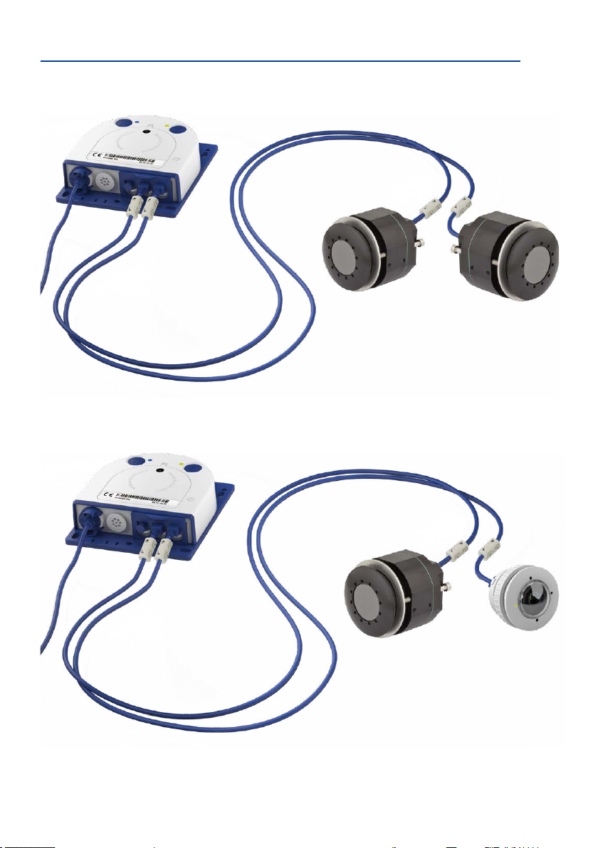
2.1.2 S16 FlexMount Installation Options
Using One or Two Sensor Modules
You can decide for yourself with the S16 whether you want to use the camera with one or
two sensor modules. You can upgrade or downgrade the system at any time.
On www.mobotix.com got
to Products > S16 DualFlex
and open the basket. It
contains the Product
Congurator, Use this to
order the required parts in
any of the available colors.
Produkt Preview:
Go to Products > S16
DualFlex to view and
order accessories for the
MOBOTIX S16 system.
3m/9.8cable
3m/9.8cable
3m/9.8cable
The S16 with a single hemispheric L10-L12 sensor module therefore essentially oers the
same range of functions as a standard hemispheric camera like the Q25M, but has the added
advantage that it can be installed even more inconspicuously and almost completely hidden.
While the sensor modules can record audio data via integrated microphones, an external
speaker can be connected directly to the camera and positioned in an appropriate place.
If the sensor module microphones are not used, an additional microphone can also be
connected directly to the camera.
Hemispheric Day and Night Camera with Sensor Modules D10/N10 (6MP) or D12/N12
(5MP)
The S16 is the rst hemispheric dual camera for use in extremely variable lighting conditions
equipped with two hemispheric lenses each with a black/white and color sensor. It is important in terms of mounting, whether on a wall or ceiling, that both the camera’s sensor modules are positioned directly next to each other and in parallel (arrows on sensor modules
pointing in the same direction) in order to see the same image area as a color image during
the day and as a black/white image at night.
50
Page 51

Preparing the Installation
Ceiling-Mounted
Indoor installation is mostly on suspended ceilings and is extremely easy. A round hole with
a diameter of 45 mm/1.77 in is all that is needed, through which a S16 sensor module with
connection cable and attached ferrite is pushed down through the ceiling panel, xed from
behind using a nut and then connected to the concealed body hidden behind a ceiling panel
(connector and lock).
3
Diam. 43 to 45 mm/1.69 to 1.77 in
Step 3:
Secure sensor module with nut
2
Step 2:
Drill hole (43 mm/1.69 in), feed
through cable with sensor module
1
Step 1:
Plug in connection cable, secure
with bayonet catch and attach
ferrite
It should be ensured when selecting installation sites that each of the sensor cables do
not exceed 3 m/9.8 (5MP – 2 m/6.6 ). The theoretical maximum distance between the
two sensor modules of a S16 where the body is placed centrally is therefore 6 m/19.7
(5MP – 4 m/13.1 ).
Caution
If there is a risk of water collecting on the back of the sensor modules (for example,
in outdoor areas or in the event of extreme humidity), the modules should not be
installed pointing downwards!
51
Page 52

S16 Camera Manual: Installation
The S16 monitors two
separate rooms
The S16 can, however, also be deployed at shorter distances between the two sensor modules with surprising results:
• Two adjacent areas separated by a dividing wall, shelves, oor or other form of screen
can be captured without any blind spots using a S16.
• In L-shaped rooms, both sensor modules are simply positioned at right angles. A S16
therefore captures the entire room without any blind spots.
The S16 can see
“around corners”
52
Room 1
Room 2
• Installing the two sensor modules next to one another, but pointing in opposite direc
tions in particularly long, narrow rooms (for example, hotel corridors, buses, aircra,
railroad cars, etc.) delivers double hemispheric images of up to 6 megapixels that, in
terms of sharpness of detail, signicantly outperforms a single hemispheric camera with
just one lens. For these kinds of installations, MOBOTIX will soon oer an appropriate
mount in the range of accessories available for the S16 (SurroundMount). The slight
downward tilt of the two sensor modules allows the area directly underneath them
to be captured without any blind spots.
-
Page 53

Preparing the Installation
Wall-Mounting
Mounting a S16 sensor module on a wall, for example, on basic partition walls or fake walls
with cavities behind the wall covering, is just as easy as mounting on a ceiling. Drill a hole
45 mm/1.77 in diameter, t the sensor module, x from behind with a locknut and connect
to the body. Depending on the installation height and the required camera focus, the cam
era can be installed with or without the wedge with 15° tilt available as an accessory.
Product preview:
SurroundMount module
with 2 x L12 sensor modules
S16 SurroundMount:
6 megapixel 360° camera
-
Mounting with or without
15° wedge (accessories)
Diam. 43 mm/1.69 in
Diam.50mm/2in*
15 mm/0.6 in
MOBOTIX also oers the appropriate installation accessories for mounting the sensor module
on thicker walls. Longer “tunnel holes” through a wall can also be bridged using several
extension pieces (each approx. 40 mm/1.6 in). The maximum wall thickness is therefore
only limited by the length of the sensor cable depending on the installation position of the
body, which is in theory 3 m/9.8 .
* Hole diameters vary
depending on material
thickness (see «Size of the
Bore Holes with Dierent
Material Thicknesses» in
Section 2.1.1, «Positioning
a Hemispheric Camera»
53
Page 54

S16 Camera Manual: Installation
S16 simultaneously
monitors indoor and
outdoor areas
MixedCeilingandWall-Mounting
By mounting a sensor module on the ceiling of a room and at the same time attaching the
second sensor module to an outside wall of this room, both the inside and the outdoor area
can be captured with a single S16 at minimal installation cost.
Example: Kiosk
Simultaneous capture of the entire sales oor and the area outside the entrance with stand-up
tables.
Indoors Outdoors
Floor-Mounting
Mounting sensor modules on the oor can also make sense for industrial uses or in areas
where there are no people. Examples of such uses are vehicle ramps where the vehicles can
also be easily captured from below.
Place sensor modules
centrally between the
wheels (along vehicle
longitudinal axis). Sensor
modules must be protected
against dirt at the top by
glass panels or similar!
Do not drive over or step
directly on the camera
or sensor modules!
54
Page 55

Preparing the Installation
(without lens)
Mounting the BlockFlexMounts
BlockFlexMounts have been designed for integration into other devices. They use the same
technology as the “regular” sensor modules, but in a black anodized aluminum housing.
Thanks to the tap holes on each side and the holes for machine bolts, the BlockFlexMounts
are easily integrated into any given structure or device.
B016 B036 B041 B061 B079
B119 B237 B500
Mounting the Sensor Modules with the PTMount
The PTMount provides for exible, weatherproof and tamper-proof installation of MOBOTIX
sensor modules. Its three axes of rotation allow installing the sensor module at any given
structure and pointing it into any viewing direction.
CS Mount
More information:
www.mobotix.com >
Products > Cameras >
S16 DualFlex
Panning
360°
Rotating
360°
Tilting
100°
This means that you can install the PTMount to any ceiling, wall and even upright.
Mounting to a Ceiling Mounting uprightMounting to a Wall
Additional Information,
Quick Installation:
www.mobotix.com >
Products > Cameras >
S16 DualFlex
55
Page 56

S16 Camera Manual: Installation
Mounting the Thermal Sensor Modules
Front Plate Mounting
Tighten the cylinder head screws (red arrows) to push the pressure plate against the wall/
faceplate. Hole diameter Ø 48 mm, possible thickness of wall/faceplate: 0 to 14 mm/0 to 0.6 in.
Hole diameter Ø 48 mm
Pressure plate
Screw Mounting
The housing can be installed by aixing suitable screws M4 (4 mm length of thread) in at
least two of the six tap holes. Remove pressure plate and cylinder head screws.
Twotapholesonright-hand
side of housing
Front plate
Remove!
Additional Information,
Quick Installation:
www.mobotix.com >
Products > Cameras >
S16 DualFlex
56
Twotapholesonle-hand
Two tap holes at bottom of
side of housing
housing
For additional information on the MOBOTIX thermal sensor modules and the Quick Installation,
see www.mobotix.com under Products > Outdoor Cameras > S16 DualFlex or Support >
Download Center > Documentation > User Manuals > Outdoor Cameras > S1x DualFlex.
Page 57

Before Mounting
2.2 Before Mounting
This section of the manual provides an overview of the variety of S16 connection options,
the preparatory steps and the tools required for mounting.
2.2.1 Overview of Cable Connections
The following cables can be used with the S16 (see also Section 1.5, «Available Accessories»):
•
MOBOTIX patch cable
the
MX-Patch-Box
•
Ethernet installation cable
an Ethernet installation cable can also be tted directly onto the integrated LSA cutting clamp.
•
MOBOTIX USB cable with MiniUSB connector
required impermeability, even in adverse weather conditions, and thereby prevents
corrosion of the connectors, for example, on an external USB hard drive.
Sensor cable for the sensor modules (S16 only)
•
to the S16 via this cable. A separate cable is required for each sensor module (max.
3 m/9.8 ).
Additional cable for MxBus connections, microphone and speaker
•
MOBOTIX modules can be connected via this multi-wire cable. The other camera opening
is used for this cable or for single wires, depending on which connection is used for
network cabling (patch or installation cable)
: This supplied MOBOTIX cable is designed for direct connection to
, the
MX-NPA-Box
or a standard network port (only in indoor areas).
: As an alternative to the
MOBOTIX patch cable
: This MOBOTIX cable provides the
: The sensor modules are connected
(see above)
: Additional
MOBOTIX patch cables
or additional cables
Additional cables or
network installation cables
MiniUSB
Cam1 Cam2
sensor module cables
57
Page 58

S16 Camera Manual: Installation
Connectors pointing down
IP66
Connectors pointing up
IP54
Only
MOBOTIX cables may be used for the Ethernet and USB connection
to the sensor modules (S16)
Caution
as well as
to ensure the camera remains permanently watertight.
Ethernet
for LAN
MiniUSB
Sensor cable
Unused connections must be secured using appropriate cable plugs and by closing
the corresponding locks
AvoidInstallingUpside-Down(ReducedWeatherProtection)
If you are installing the S16 upside-down (i.e., the connectors are pointing upwards), the
camera does not reach protection class IP66 any more, but only IP54. If mounted upsidedown, the S16 can only be used in a dry indoor environment.
Removing MOBOTIX Cables and Plugs
The corresponding lock must rst be removed or released to remove one of the cables or
plugs indicated above from the S16:
to protect the inside of the housing against water and dust.
Patch Cable MiniUSB Sensor Cable
1. Turn the bayonet catch to the le.
2. Remove the bayonet catch.
3. Remove the cable/plug.
1. Pull the triple retainer upwards
(away from the base plate) until it
clicks into place.
2. Remove the cable/plug.
58
Page 59

Before Mounting
Inserting and Locking MOBOTIX Cables and Plugs
The corresponding lock must be applied or closed again aer inserting one of the cables or
plugs indicated above into the S16:
Patch Cable MiniUSB Sensor Cable
1. Insert the cable/plug.
2. Attach bayonet catch.
3.
Turn the bayonet catch to the right.
1. Insert the cable/plug.
2. Push the triple retainer down
(towards the base plate) until it
clicks into place.
2.2.2 Notes on Cable Lengths and Power Supply
•
Power is supplied to the camera via the camera Ethernet connection (patch or installation
cable). We recommend using a MOBOTIX PoE adapter or another similar high-quality
PoE product to loop-in the power supply:
– One camera: with the PoE adapter (MX-NPA-PoE or MX-NPA-Box)
– Multiple cameras: with PoE products conforming to IEEE 802.3af (PoE switch)
• The maximum length of the network cable for power supply over an Ethernet cable
is 100 m/110 yd.
•
Make sure that you only use switches or routers that support the 10/100 Mbps network
interface of the camera.
• We highly recommend using uninterruptible power supplies (UPS) to provide backup
power.
• If you are using IEEE 802.3af or IEEE 802.3at (PoE+) Power-over-Ethernet network
components to supply power to MOBOTIX cameras, make sure, if possible, that these
components do not have a fan. Since the power consumption of MOBOTIX cameras is
very low compared to other products, the reliability of the entire system is increased,
thus extending the life of these components.
Caution
Max. power consumption of attached extension modules: The power consumption
of all attached
the MxBus connector
MxBus modules
and
modules must not exceed 4 W, if the camera is powered by PoE class 3
is used,
the camera cannot power any peripheral devices!
must
not exceed 3 W
the USB socket, the
. When attaching modules to
power consumption of all attached
. If
PoE class 2
For more information on changing the PoE class, please see Section 2.4.7, «Variable PoE»).
59
Page 60

S16 Camera Manual: Installation
Patch cable
Further cables
2.2.3 Network Connection with MOBOTIX Patch Cable
The supplied
an
MX-NPA-Box
Connecting the Patch Cable to the Camera
First remove the blue bayonet catch and the blue sealing plug
in the le-hand connector on the S16. Then insert the MOBOTIX
patch cable into the camera and secure the cable using the
bayonet catch.
ConnectingthePatchCabletoanMX-Patch-Box,MX-NPA-Boxor
Standard Network Port
First remove the blue bayonet catch and the blue sealing plug
in the right-hand connector on the box to establish the network
connection to an MX-Patch-Box or MX-NPA-Box. Then insert the
MOBOTIX patch cable into the box and secure the cable using
the bayonet catch.
More information on installing an
is available at www.mobotix.com under Support > Download
Center > Documentation > User Manuals > Accessories >
Interface Boxes.
Insert the MOBOTIX patch cable of the S16 into the network port for standard connections
(only permitted in indoor areas).
Connecting Peripheral Devices (MxBus, Microphone, Speaker)
The opening provided for the installation cable must be used
for all other cables that are connected to the camera when
using the MOBOTIX patch cable. Depending on the cable used,
the single wire plug installed must be replaced with one of the
other cable plugs (M.4/5).
MOBOTIX patch cable
or to a standard network port.
can be used to connect the camera to an
MX-Patch-Box
or
MX-NPA-Box
MX-Patch-Box
Patch cable
,
The cable used must be xed to the circuit board using one of the cable ties supplied (M.9)
to ensure that less strain is placed on the cable. The individual cable wires must be xed on
the screw clamps using the the screwdriver supplied (M.9).
60
Page 61

Before Mounting
Installation cable
Further cables
for sensor modules
2.2.4 Network Connection with Installation Cable
As an alternative to connection to an MX-Patch-Box, MX-NPABox or standard network port, you can also connect the S16
directly to an
camera must be opened for this purpose, this working step
S16 must be carried out before
housing cover is no longer accessible once it has been mounted.
The installation cable is xed onto the circuit board before tting the wires onto the LSA
cutting clamps using one of the cable ties supplied (M.9) to ensure less strain is placed on
the cable and that the camera is earthed correctly.
Connecting Peripheral Devices (MxBus, Microphone, Speaker)
The opening provided for the MOBOTIX patch cable must be
used for all other cables that are connected to the camera when
using an installation cable. The blue bayonet catch and the
blue sealing plug in the le-hand connector must be removed
for this purpose. The single wire plug or one of the other cable
plugs (M.4/5) is then pushed into the opening, depending on the cable used. The bayonet
catch will no longer be used.
The cable used must be xed to the
ensure that less strain is placed on the cable. The individual cable wires must be xed on
the screw clamps using the the screwdriver supplied (M.9).
2.2.5 Using Sensor Modules (S16 Only)
installation cable
. Since the housing cover of the
in a
mounting the camera as the
base plate
using one of the cable ties supplied (M.9) to
One or two sensor modules can be connected via both right-hand
connectors in the S16. For this purpose, the lock is pulled forward, the central and right-hand (or only the central plug if only
one sensor module is used) is removed and the corresponding
sensor cable is inserted. The connectors are waterproof again
once the lock is pressed down.
2.2.6 Using the MiniUSB Cable
Existing add-on modules such as the MOBOTIX ExtIO (USB) or
external USB hard drives can be connected via the MiniUSB
connector. For this purpose, the lock is pulled forward, the lehand plug is removed and the MiniUSB cable is inserted. The
connectors are waterproof again once the lock is pressed down.
Sensor cable
MiniUSB cable
61
Page 62

S16 Camera Manual: Installation
Mic Speaker MxBus
2.2.7 Using MxBus Modules
The MxBus camera connector is located under the housing
cover (clamps 5 and 6 of the screw clamps) and allows the
operation of additional modules for expanding functionality
(e.g. connection of an MX-GPS-Box for determining time and
position). MxBus was optimized specically for the use of
existing two-wire cables.
The terminal connector has two connectors to connect an MxBus
module (other MxBus modules can then be connected from
there). The length of the entire MxBus cable may not exceed
50 m/55 yd.
The MxBus wires that are to be stripped at the end should always be fed into the
camera through appropriate plugs before mounting. If the
single wire plug is used, one wire must be pushed through
a hole in the plug.
Do not mix up the polarity of the cables during installation.
Select a consistent cable color for +/– in the entire MxBus
system (for example, red = +, blue = –)
Aer an MxBus module has been connected, the MxBus itself must be started in the
camera’s web-based user interface (if this has not been done yet) as well as the actual
module (Admin Menu > Manage Hardware Expansions or MxBus Modules).
Mic Speaker MxBus
Note
62
2.2.8 External Audio Support (Microphone/Speaker)
The camera connector for an external microphone and an
external speaker is located under the housing cover (clamps
1 and 2 of the screw clamps for microphone, clamps 3 and 4
for speaker).
An external microphone (red box) and an external speaker
(red box) with the following technical data can be connected
on the terminal connector:
Microphone
•
–35 ± 4 dB, for example, Panasonic Microphone Capsule WM61
•
Speaker
Speaker K36WP or K50WP
: Vs = 2.0 V, RL = 2.2 kOhm, sensitivity
: Max. power output 400 mW at 8 Ohms impedance, for example, Visaton
Page 63

Before Mounting
2.2.9 Replacing the MicroSD Card
If the pre-installed MicroSD card needs to be replaced (for example, with a 64 GB MicroSD
before
card), it is best to do so
the camera is installed.
MicroSD cards should only be
replaced when the camera is disconnected from the power supply.
1.
Remove rotary plug
of the housing, for example, using a suitable coin and
remove the plug.
Remove the MicroSD card
2.
card into the holder using a pair of tweezers until you
click
hear a
can be removed using the tweezers.
3.
Insert the MicroSD card
shown (electrical contacts pointing towards the front)
into the card slot using a pair of tweezers. Make sure
that you hear a
card is now locked and can be used.
ne w Mic roS D car d, it ne eds to be fo rma tted rst
Section 3.5.2, «Formatting the MicroSD Card»).
4.
Attach t he rotary pl ug
and screw it tight using a coin (approximately two turns,
the plug slot is pointing forwards).
: Loosen the rotary plug at the top
: Carefully push the MicroSD
. The card is now sticking out slightly and
: Push the MicroSD card as
click
when the card is inserted. The
If you are us ing a
(se e
: Insert the rotary plug as shown
2.2.10 Tools Required for Installation
Replace the MicroSD
card only if the camera
is disconnected from
the power supply!
Click!
Click!
Please make sure that all the camera components are included in the original packaging
(see Section 1.5, «Available Accessories»).
Additional Tools/Materials Required
•
Any additional materials required for attaching the camera to a ceiling/wall (four wood
screws including screw anchors and washers) are included in the original packaging.
• Screwdriver with PZ 2 driver bit
• Optionally a powerdrilland6-mmdrillbit for screw anchor holes for attaching the
base plate
• Drilling templates for base plate and sensor module (see www.mobotix.com >
Support > Download Center > Documentation > Drilling Templates)
• Scissors to cut out the template.
• Pencil to mark the drill holes
63
Page 64

S16 Camera Manual: Installation
Only use the LSA/
Krone blade and set
to LOW impact!
Do not cover pressure
equalization elements
•
Optionally LSA+ tool for tting an installation cable onto the LSA terminals of the camera
•
Hole saw or Forstner drill with 44 to 45 mm/1.77 in diameter for the S16 sensor modules
or with 35 mm/1.38 in diameter for the S16 lens
• So cotton cloth to clean the front of the lens aer installation
2.2.11 Preparatory Steps
Make sure of the following before starting to install the camera:
•
Connection with MOBOTIX patch cable
: The network connector has been guided either
with an MX-Patch-Box, an MX-NPA-Box or a standard network port (only permitted in
indoor areas) into the vicinity of the mounting position of the camera.
•
Connection with installation cable
: If a network installation cable is used instead, it
may not conduct any voltage and may not be connected to the network.
•
Even surface
: Make sure before attaching the camera that the surface is even so that
the base plate of the camera does not move.
•
Pressure equalization element
: This element on the housing of the S16 and the
sensor modules must be kept free to enable pressure equalization element of the
camera housing.
64
S16 DualFlex (front) Sensor module (rear)
Page 65

Installing the S16 FlexMount
1 2
Pressure compen-
sation
Base plate
L
LEDs
MicroSD card
Key
Triple cable retainer
Bayonet catch
S16 housing cover
2.3 Installing the S16 FlexMount
2.3.1 Attaching the S16 Body
LED defaults:
1 Power (on), Error (ashes)
2 Recording (ashes)
Use the drilling templates available on www.mobotix.com, Support > Download Center >
Documentation > Drilling Templates to mark the position for drilling the dowel holes for
the camera and the sensor modules. Make sure that the drilling template is not scaled down
when printing or copying the drilling template.
Caution
Make sure the camera is mounted on an even surface. If this is not the case, there is
a risk that the base plate will be warped and the housing may leak.
The torque for the
Onlyexchangesensormoduleswhenpoweredo: Make sure that the camera‘s power
housing cover screws
is 0.4 Nm.
supply has been disconnected before attempting to exchange any sensor modules.
Installing the Camera at a Back Wall
If you are installing the S16 at a back wall using its base plate, the installation of the camera
is nished with just a few steps:
1. If necessary, mark the drill holes at the intended mounting position, drill the holes for
the base plate and hammer in the 6 mm dowels supplied.
The drilling templates
can be found at the
end of the manual
Always print or copy
drilling templates in
their original size
65
Page 66

S16 Camera Manual: Installation
Max. 10 cm/4 in!
2. If this has not been done already, insert the cable tie needed to ensure that less strain
is placed on the connection cable into the slot provided below in the base plate with
out closing it.
3. Screw on the S16 body using the 4×40 mm screws included (or other suitable screws)
and washers (with a diam. of 4.3 mm).
2.3.2 Attaching and Connecting the S16 Sensor Modules
-
Only
MOBOTIX cables
should be used to connect
the sensor modules (see
Section 1.5.9, «Connection
Cable for Sensor Module»)
The sensor module
connection cables must
never be bent sharply!
Before installing the sensor modules, make sure that the sensor cables will reach the intended
mounting position without placing a strain on the cables. Further information on the individual camera connectors can be found in Section 2.2.1, «Overview of Cable Connections».
Drill the hole for the sensor module at the intended mount-
1.
ing position (arrow on the back of the sensor module
pointing “Up”).
2. Connect the sensor cable to the sensor module (turn the
blue bayonet catch to the le and li o, remove the plug,
insert the sensor cable, replace the bayonet catch and
turn to the right). Make sure that the sensor cables are
not sharply bent anywhere!
Attach one ferrite at each end of the sensor cable (max. distance to the plug 10 cm/4 in,
3.
as shown in the gure).
4. If extensions are required (at least one in sensor module
L12 and 15° wedge), they should now be pushed over the
sensor cable and joined to the sensor module or extensions
that have already been mounted using the bayonet catch
(see Section 2.3.3, «Plugging in and Removing Extensions»).
66
Page 67

Installing the S16 FlexMount
M
O
B
O
T
I
X
M
O
B
O
T
I
X
Make sure MOBOTIX
lettering is pointing
upwards!
5. If a 15° wedge is used on the outside, the visible wedge
and the wedge sealing must now be pushed onto the cable,
the sensor module and any extensions already mounted
(the thicker side of the wedge is at the top). Make sure
that the MOBOTIX lettering at the front of the sensor
module is pointing upwards!
Now insert the cable and then push the whole sensor module (including wedge, wedge
6.
sealing and extension, if installed) through the hole.
7. If a 15° wedge has been tted on the outside, the second
wedge sealing and the second wedge must now be pushed
from the inside over the sensor cable, any installed extensions and the sensor module (the thicker side of the wedge
is at the bottom) may need to be shied to ensure that
the nut is properly positioned on the back.
8. Feed the sensor cable through the nut and secure the
sensor module and mounted extensions using that nut.
If you need to seal o the sensor module against the wall,
you should apply silicone sealant before tightening the nut.
9. Attach the sensor cable of the rst sensor module to the Cam1 connector and the
sensor cable of the second sensor module to the Cam2 connector of the S16 (pull the
blue triple cable retainer up, remove the plug, insert the sensor cable and push the
cable retainer down again).
2.3.3 Plugging in and Removing Extensions
The extensions are xed onto the sensor modules (or other extensions) with the help of a
bayonet catch.
If you install a S16 with
automatic day/night
switching, make sure to
connect the D11 (day)
sensor module on the
Cam1 and the N11 (night)
sensor module on Cam2
67
Page 68

S16 Camera Manual: Installation
1
2
3
Attaching Extensions
1. Turn the sensor module so that the larger lobe (red arrow
on the illustration) is at the front. The other three lobes
are smaller and do not protrude (blue arrows).
Turn the extension so that the larger lobe on the extension
2.
is slightly oset from the lobe on the sensor module (see
blue box in the illustration on the right). Push the extension
with the notches onto the sensor module.
3. Turn the extension in a clockwise direction until it clicks
into place (viewed from the right). The extension will
lock automatically and will not turn, even if the nuts are
loosened.
Make sure that the extensions are always connected as described in Step 2. Attaching
the extensions incorrectly will damage the bayonet catch and may result in the nuts
not being properly attached.
Note
Removing Extensions
Proceed as follows to loosen and undo an extension lock:
Push the extension towards the sensor module to unlock
1.
it.
2.
Turn the extension in an anti-clockwise direction (viewed
from the back) to open the bayonet catch.
3. Remove the extension.
68
Page 69

Network and Power Connection, Additional Cables
Patch cable
Patch cable
2.4 Network and Power Connection, Additional Cables
2.4.1 Network Cabling for S16 with Patch Cables
Using a patch cable and an MX-Patch-Box or MX-NPA-Box oers the following advantages:
• Quick installation/deinstallation
• No shortening of the cable in the event of multiple installation/removal
• Connection that is dust-proof/resistant against water jets in accordance with IP66
Connecting the Patch Cable to the Camera
First remove the blue bayonet catch and the blue sealing plug
in the le-hand connector on the S16. Then insert the MOBOTIX
patch cable into the camera and secure the cable using the
bayonet catch.
ConnectingthePatchCabletoanMX-Patch-Box,MX-NPA-BoxorStandardNetwork
Port
First remove the blue bayonet catch and the blue sealing plug
in the right-hand connector on the box to establish the network
connection to an MX-Patch-Box or MX-NPA-Box. Then insert the
MOBOTIX patch cable into the box and secure the cable using
the bayonet catch.
More information on installing an
is available at www.mobotix.com under Support > Download
Center > Documentation > User Manuals > Accessories >
Interface Boxes.
Insert the MOBOTIX patch cable of the S16 into the network port for standard connections
(only permitted in indoor areas).
If additional cables are required inside the housing (MxBus, microphone, speaker), they must
be connected as described in Section 2.4.3, «Connecting Additional Cables».
MX-Patch-Box
or
MX-NPA-Box
69
Page 70

S16 Camera Manual: Installation
~35 mm
2.4.2 Network Cabling for S16 with Installation Cables
1.
Remove housing cover and cable
plugs
: Loosen the Allen screw on the
housing cover of the S16 and remove
it. Push the cable plug in the camera
out of the housing from the inside to
the outside (red arrow).
Ensure that the installation
cable is fed right into the
housing when the camera is
in the right position so that
the cable plug provides optimal sealing for the housing
Attach the cable ties
2.
: Feed one of
the cable ties supplied through both
slots in the circuit board underneath
the LSA cutting clamp.
Prepare the installation cable
3.
Cut the installation cable to length,
feed through the white single wire
plug (5-7 mm/0.2 to 0.28 in), remove
35 mm/1.38 in of insulation and separate into individual twisted wire
pairs including 15 mm/0.6 in sheathing. Wind the shield mesh around the
sheath to a width of 10 mm/0.4 in so
that it can be xed on the contact
surface later using the cable tie.
Secure the cable
4.
: Push the plug
out and insert the installation cable
with single wire plug (5-7 mm/0.2 to
0.28 in) into the opening intended
for the installation cable. The rubber
sleeve must sit tightly on the installation cable to prevent the penetration of moisture. Tighten the cable
tie around the shield mesh to ensure
less tension.
:
~10 mm
~15 mm
Shield meshCable sheath Wire shield
~20 mm
70
Connecting the cable wires
5.
: The
individual wires of the installation cable can be connected to the LSA cutting clamp
using an appropriate tool and in accordance with the EIA/TIA-568A or B standard used
(see printed color coding above the clamp; see red arrow in the illustration below).
Page 71

Network and Power Connection, Additional Cables
Caution
Make sure that
not, this could lead to
Hint
: Hold the cable ends rm before cutting them with the LSA+ tool.
all cable end ocuts are removed from inside the camera
short circuits
!
. If
Only use the LSA/
Krone blade and set
to LOW impact!
If additional cables are required inside the housing (MxBus, microphone, speaker), they must
be connected as described in Section 2.4.3, «Connecting Additional Cables».
71
Page 72

S16 Camera Manual: Installation
Additional cables
(MxBus, microphone, speaker)
2.4.3 Connecting Additional Cables
Additional cables can be fed through the free opening in the housing, depending on the
Ethernet connector used (patch cable or installation cable). If an installation cable is used,
additional cables should be installed aer the installation cable has been tted.
Ethernet via Patch Cable Ethernet via Installation Cable
Additional cables
(MxBus, microphone, speaker)
1.
Replace any single wire plugs with
appropriate cable plugs (M.4/5) for
additional cables.
1. Remove the bayonet catch and
the patch cable and push the sin
gle wire plug or appropriate cable
-
plug (M.4/5) in so that the edges
protrude inside. The bayonet catch
will no longer be used.
2. Push the single wire plug with the individual wires through or push the cable with
sheathing through the cable plug.
3.
Connect the wires to the corresponding screw terminals
with the help of the screwdriver supplied.
Mic Speaker MxBus
4. Fix single wires or cables to the base plate using one of
the cable ties supplied.
5. Connect wires to the corresponding devices (MxBus
module, microphone, speaker).
72
Page 73

Network and Power Connection, Additional Cables
PoE adapter
2.4.4 Power Supply Using a Switch
1. Connect the factory pre-installed cable of the camera to the Camera connector of
the PoE adapter.
2. Connect the LAN/Power con nector of the PoE adapter to the Ethern et con nector of
the switch/router or the Ethernet port.
3. Plug the RJ45 connec tor of the power supply unit into the PC/Power connector of
the PoE adapter.
Switch/router
LAN/www
(10.8.0.11/255.0.0.0)
(MX-NPA-PoE)
LAN/Power
RJ45
PC
Camera
RJ45
Power supply unit
RJ45
PC/Power
Camera
(10.8.0.99)
The IP addresses in
the diagram are shown
only as an example
For the S16 you should use
the blue MX-NPA-PoE-Set
or the MX-NPA-Box
vious MOBOTIX network
power accessories, such
as the NPA-Set, PowerBox and Power-Rack
(MX-NPA-Set, MX-NPR-4
and MX-NPR8/20) are not
suitable for use with the S16
– pre-
73
Page 74

S16 Camera Manual: Installation
2.4.5 Power Supply When Connected Directly to a Computer
1. Connect the factory pre-installed cable of the camera to the Camera connector of
the PoE adapter.
The IP addresses in
the diagram are shown
only as an example
The PoE adapter replaces
the crossover cable
when directly connecting to a computer
For the S16 you should use
the blue MX-NPA-PoE-Set
or the MX-NPA-Box
vious MOBOTIX network
power accessories, such
as the NPA-Set, PowerBox and Power-Rack
(MX-NPA-Set, MX-NPR-4
and MX-NPR8/20) are not
suitable for use with the S16
The IP addresses in
the diagram are shown
only as an example
– pre-
2. Connect the PC/Power connector of the PoE adapter to the Ethernet port of the
com puter.
3. Plug the RJ45 connec tor of the power supply unit into the L AN/Power connector
of the PoE adapter.
PoE adapter
Power supply unit
(MX-NPA-PoE)
LAN/Power
RJ45
Camera
RJ45
Camera
(10.8.0.99)
PC/Power
RJ45
PC
(10.8.0.11/255.0.0.0)
2.4.6 PowerSupplywithPower-Over-EthernetProducts
Connect the factory pre-installed cable of the camera to the Ethernet connector of the PoE
switch/router. The switch/router must support the PoE standards IEEE 802.3af or IEEE 802.3at.
LAN/www
PoE/PoE+
switch/router
74
Camera
(10.8.0.99)
PC
(10.8.0.11/255.0.0.0)
Page 75

Network and Power Connection, Additional Cables
2.4.7 Variable PoE
The power consumption of the camera depends on the functions in use as well as any peripheral devices connected (see table). PoE classes 1, 2 or 3 may be selected in the browser-based
user interface in order to optimally adjust the camera to your system design (PoE switch in
use, emergency power concept, etc.).
PoE Power Level Classes (IEEE 802.3af Standard)
Class Max. power consumption Camera operating mode and peripheral devices
1 0.44 W–3.84 W
2 3.84 W–6.49 W Normal mode; max. 1 W for MxBus peripheral devices
3 6.49 W–12.95 W
If the total power consumption of the camera and peripheral devices exceeds the
power provided by the PoE switch for the specied class, the switch can disconnect
the camera from the power supply.
again once the peripheral devices have been disconnected from the camera and
the camera has been restarted.
LowPower mode; no peripheral devices (available
soon)
FullPower mode; max. 2.5 W for MxBus peripheral
devices (for example, MX-GPS-Box and MX-232-IO-Box
to MxBus), max. 4 W for peripheral devices to MxBus
and USB interface
Caution
In this case, the camera will only be accessible
The default setting is usually ne, and nothing needs to be changed. However, the PoE power
class must be changed in the browser if a higher or a lower power class is required for your
application:
Select Admin Menu > Network Setup >
1.
Ethernet Interface (for experts).
Click on Change under Power Supply.
2.
3. A Power Wiz ard will ap pear to guide
you through the PoE conguration
steps.
Ne xt, re star t the ca mer a: Di sco nne ct
4.
the camera from the power supply.
Then reconnect it, for example, by
disconnec ting and ten reconnecting
th e E thern et cabl e a t the PoE swi tch.
Variable PoE: Multiple
cameras can be operated simultaneously
from the same switch
75
Page 76

S16 Camera Manual: Operating the Camera
3 OPERATING THE CAMERA
3.1 Manual and Automatic Operation
Download the free-of-charge
MxManagementCenter soware at www.mobotix.com
MOBOTIX cameras do not require any extra soware. Thus, you can set up and operate the
MOBOTIX camera using a JavaScript-enabled browser on all common operating systems
(such as Windows, Linux, Macintosh, etc.). As an alternative, you can also use the MOBOTIX
application MxManagementCenter. Follow these steps to set up the camera:
1. Connect the camera to the network.
Power is supplied directly via the Ethernet cable (see Section 2.4, «Network and Power
Connection, Additional Cables»)
Establish a connection to the camera and adjust the network settings, if required.
2.
By factory default, MOBOTIX cameras are booting as DHCP client with an additional xed
IP address in the 10.x.x.x range (e.g., 10.16.0.128). Local computer networks
usually have IP addresses in the 172 or 192 ranges. Depending on whether a DHCP server
is present on the local network (e.g., a DSL router) or if the network has been set up to
use xed IP addresses, there are several possibilities for establishing a connection to the
camera and to change its network parameters:
• Network with DHCP server
– Using a browser:
If you know the IP address that the DHCP server assigned to the camera, simply
enter that address in the browser address bar to directly connect to the camera
(see Section 3.2.2, «First Images and the Most Important Settings in the Browser»).
– Using MxManagementCenter:
With MxManagementCenter, you can show and integrate the camera without
having to know its current IP address (see Section 3.2.3, «First Images and Network
Parameter Conguration in MxMC»).
76
Page 77

Manual and Automatic Operation
• Network with xed IP addresses
In order to access the camera, it must have an IP address within the range of the local
network. To set the camera’s network parameters, you can use one of these methods:
– Manually using a browser:
First, you need to change the network parameters of your computer (see Section 3.2.2,
«First Images and the Most Important Settings in the Browser» and following …).
–
Integration into MxManagementCenter with automatic adjustment of the camera’s
IP address:
The camera is displayed in MxManagementCenter despite the fact that the IP address
is not part of the local network. The application allows reconguring the network
parameters accordingly (see Section 3.2.3, «First Images and Network Parameter
Conguration in MxMC»).
3. Congure the camera.
Using the web-based user interface or MxManagementCenter.
Camera soware
in the browser
77
Page 78

S16 Camera Manual: Operating the Camera
Pressing the “L” key will
prompt the camera to
announce its current IP
address on the camera
speaker (see the gure
in Section 3.2.4, «Start
Options of the Camera»)
3.2 First Images and the Most Important Settings
Once the MOBOTIX camera has been connected to the network, you need to set up the camera’s network interface accordingly. This step involves setting up and checking the network
parameters of the camera. If your network is already using an IP address in the 10.x.x.x
range with a 255.0.0.0 network mask, you do not need to change the camera’s network
parameters. You can access the camera directly (see Section 3.2.2). If your network or computer
does not use an IP address in the 10.x.x.x range (for example, in the 192 or 172 ranges), you
should follow one of the following methods for changing the camera’s network parameters:
• Manual setup (Section 3.2.1)
• Automatic setup using MxManagementCenter (see Section 3.2.3)
Note
We will use a camera with the factory address 10.8.0.99 in the following examples.
Replace this IP address with the IP address of your camera. You will nd the IP address
of your camera on a small sticker on the camera. Make sure that the IP addresses used
in the following examples are not already being used by other devices in the network.
3.2.1 Manually Setting Up the Network Parameters in a Browser
You need a computer that is using a 10.x.x.x IP address in order to manually set up the
network parameters of the MOBOTIX camera. The computer’s network parameters usually
have to be changed for this purpose.
Entry in "Subnet mask"
eld:
255.0.0.0
78
1. Change the network parameters of your computer:
Windows (XP, Vista and 7):
1. Open Start > Settings > Control Panel > Network
Connections. Clicking Properties opens the dialog box
shown.
2. Double-click Internet Protocol (TCP/IP). On the
General tab, activate the Use the following IP address
option. Enter an IP address in the 10.x.x. x range in this
eld (for example, 10.8.0.11).
3. Once all dialog boxes have been closed, the computer
will have the IP address 10.8.0.11 .
Page 79

First Images and the Most Important Settings
Windows 8.1:
1. Open Start > Settings > Control Panel > Network
Connections. Clicking on Properties opens the dialog
box shown.
2. Double-click on Internet Protocol (TCP/IP). On the
General t ab, ac tiva te the Use the following IP address
option. Enter an IP address in the 10.x.x.x range in this
eld (for example, 10.8.0.11).
3. Once all dialog boxes have been closed, the computer will have the IP address
10.8.0.1 1 .
Linux/Unix:
1. Open a terminal as root user.
2. Enter the following command: ifconfig eth0:1 10.8.0.11
3. The computer is now also using the IP address 10.8.0.11
Mac OS X:
1. Open
System Properties > Network.
2. Select Ethernet. In the Conguration eld, select
Manual and enter a 10.x.x.x IP address (for example,
10.8.0.1 1).
3. Click Apply on th e bot tom rig ht-hand s ide of th e dial og
box to assign the computer the IP address 10.8.0.1 1 .
Entry in ”Subnet mask”
eld: 255.0.0.0
79
Page 80

S16 Camera Manual: Operating the Camera
2. Set up the target network parameters of the MOBOTIX camera:
1. Open a web browser on the computer and enter the default IP address of the MOBOTIX
camera in the address bar of the browser (for example, 10.8.0.99). Clicking Enter
displays the user interface of the MOBOTIX camera (see also Section 3.2.2, «First Images
and the Most Important Settings in the Browser»).
Default user data
User name:
admin
password:
meinsm
2. Click on the Admin Menu sobutton in the user interface of the MOBOTIX camera.
The Quick Installation starts automatically once the
admin user has log ged on.
Note: The Quick Installation can also be executed at a later stage by opening Admin
Menu > Network Setup > Quick Installation.
Enter the target network parameters of the camera on
3.
th e appro pri ate page of the Qu ick Ins tal latio n assist ant .
Note: The network parameters can also be modied retrospectively via Admin Menu > Network Conguration >
Quick Installation
.
4. Once you have completed the Quick Installation and rebooted the camera, the new
network parameters will be activated. The camera can now be connected to the
target network and, if required, further congured.
80
Page 81

First Images and the Most Important Settings
3.2.2 First Images and the Most Important Settings in the Browser
Once the MOBOTIX camera has been connected to the power supply and to the network,
you can access the user interface with the live camera image in the web browser. Internet
Explorer, Firefox, Safari or any other graphical browser with activated JavaScript is suitable.
It does not matter which operating system is used.
Aer entering the camera’s IP address in the browser address bar, you will see the live view
of the MOBOTIX camera with its user interface controls, such as sobuttons, buttons for the
dierent camera screens, pull-down menus (Quick Controls), icons for accessing the online
help and the camera status, and status information elements.
Camera views
Quick controls
Softbuttons
Camera status and help
Note
Default access data for the administration menu
• User name:
• Password:
(Note that you need to change the password upon your rst login – camera release
V5.1.x and higher.)
admin
meinsm
81
Page 82

S16 Camera Manual: Operating the Camera
Live view:
http://<camera IP>/
control/userimage.html
Player screen: http://<camera IP>/control/player
MultiView screen:
http://<camera IP>/
control/multiview
Guest screen: http://<camera IP>/cgi-bin/
guestimage.html
Camera Views: Live, Player, MultiView
The MOBOTIX camera automatically displays the
live screen when it starts up (factory default setting). You can set a dierent start page in Admin
Menu > Language and Start Page (for example,
the Guest screen) to allow a restricted access to
the live image.
The other available standard screens include
Player (playback of recorded images and video
sequences) and the MultiView screen (displays
several cameras with live or recorded images).
MultiView allows you to view several cameras via
a “proxy” camera (especially useful if you want to
access your cameras from outside of the network
with reduced bandwidth) and the PDA mode pro
vides a special screen for mobile devices.
-
82
Note
Click on the icon in the top right corner of the camera's user interface in the browser
to nd further information on the dierent camera screens.
Page 83

First Images and the Most Important Settings
3.2.3 FirstImagesandNetworkParameterCongurationinMxMC
Installing and Starting MxManagementCenter
Download and install the current version of MxManagementCenter from the MOBOTIX web
site (www.mobotix.com>Support > Download Center > Soware Downloads in the
MxManagementCenter area). Double-click the shortcut for the program or the program le.
Finding Cameras
When starting MxManagementCenter for the rst time, the conguration wizard opens and
automatically starts searching for MOBOTIX cameras. The number of found cameras is shown
next to the Add button. This number is updated automatically if the number of MOBOTIX
cameras on the network has changed (i.e., by connecting new/disconnecting existing cam
eras)..
Click on Add Devices. The cameras are displayed either in a list or as tiles. Use the List and
Tile buttons to change the display mode.
-
-
Download
MxManagementCenter
for free from
www.mobotix.com
MxManagementCenter automatically monitors and displays the operating status of all cameras. Cameras that are not on the same subnet as the computer are indicated by the
Icon (Camera not in the same network as the computer). Likewise, the cameras that have an
unknown password or for which no user name/password combination has been specied in
MxManagementCenter will be displayed with the icon
(Camera is password-protected).
83
Page 84

S16 Camera Manual: Operating the Camera
ReconguringNetworkAddressesofCameras
Using Bonjour*, MxManagementCenter nds not only cameras on the same network as your
computer, but also MOBOTIX cameras located in other subnets (status:
you would not be able to establish any connection to cameras in a dierent network or subnet.
This is the case, for example, if you are integrating cameras into a network without DHCP
server (i.e., with xed IP addresses) and the IP address range is dierent from the 10.x.x.x
range supported by the cameras in addition to DHCP.
MxManagementCenter can automatically congure such a camera so that it is ”integrated”
into your existing network. To do so, you have to select the respective camera and then click
on the
The Network Setting dialog opens.
If you have assigned a xed IP address to your computer, you will certainly prefer to assign
xed IP addresses to the cameras. To do so, enter the IP address and the subnet mask. The
IP address is incremented automatically for each selected camera.
button at the bottom of the program window.
). In such a case,
84
When you click on Apply, the selected cameras are automatically recongured and they are
located in the same subnet as the computer.
Page 85

First Images and the Most Important Settings
3
Adding Cameras
Aer a camera has been recongured, it has the status Accessible and can be integrated
into MxManagementCenter.
Select the desired cameras (use Cmd/Ctrl-click to select several cameras). If the cameras
are password-protected
and password.
, click on Edit User and Password 2 and enter the user name
1
2
1
3
The number of selected cameras is shown on the Next button
and click on Finish.
For more information, see the MxManagementCenter Tutorial, which can be downloaded as
a PDF le from the MOBOTIX website: www.mobotix.com > Support > Download Center >
Documentation > Brochures & Guides > Tutorials.
. Move to the next page
85
Page 86

S16 Camera Manual: Operating the Camera
L
1 2
LED default settings:
1
Power (on),
Error (ashing)
2
Recording (ashing)
3.2.4 Start Options of the Camera
By default, the camera starts as DHCP client and automatically tries to get an IP address
from a DHCP ser ver. To start the camera in a mode dierent from the default mode, you can
activate the boot menu of the camera.
Preparing the Camera
• Disconnect the camera’s power supply.
• Reconnect the power supply of the camera.
Activating the Boot Menu
The right LED lights up red 5 to 10 seconds aer establishing the power supply and will stay
on for 10 seconds. Briey press the key indicated by the red circle in the gure. The camera
enters the boot menu, ready for selecting one of the start options.
The LED now ashes once and repeats the ash signal aer pausing for one second (the
number of ashes indicates the current start option). To go to the next start option, briey
press the key again (< 1 sec). Aer the last start option, the camera returns to the rst option
(LED ashes once).
LED
ashes
1 x
2 x Factory Defaults
3 x
4 x Recovery System
*Only on cameras with audio option and installed speaker.
Start Option Meaning
Auto
Conguration
Automatic IP
Address
Starts the auto conguration in order to operate this camera as
a door station (variant Mx-S16B only, camera soware V5.2.x and
higher).
Starts the camera with factory defaults (factory default IP address,
users and passwords will not be reset).
Starts the camera as DHCP client and tries to obtain an IP address
from a DHCP server. If a DHCP server cannot be found or no IP
address can be obtained, the camera starts with its factory default
address.
Starts the camera with the recovery system, e.g., in order to recover
from a failed update of the camera soware.
Selecting a Start option
Press the key longer (> 2 sec). The camera conrms the selection by ashing rapidly three
times. You can now remove the paper clip. Aer 20 sec, the camera will conrm the selection
by playing a sound according to the table above.
If nothing is selected, the camera will resume its normal boot process aer a certain time.
86
Audio
Conrmation*
Phone ringing
Boing
Boing Boing
Alarm Sound
Page 87

First Images and the Most Important Settings
Starting the Camera with Factory Default (Network) Settings
If you use the camera’s start option 2 to load the factory conguration, this conguration is not automatically saved in the camera’s ash memory. When the camera is next
rebooted without using start option 2, the last stored conguration will be used. To
permanently store the new conguration in the camera’s ash memory, open Admin
Menu > Store. Note that you can restore specic parts of the camera conguration
aerwards by using “Restore” to re-apply the settings still stored in the camera.
As opposed to resetting the camera using Admin Menu > Reset conguration to
factory defaults, the user information will not be reset if the camera is booted using
the factory settings.
Starting the Camera with an Automatic IP Address (DHCP)
Starting the camera using start option 3 and an automatic IP address (DHCP) is only
temporary. The network conguration of the camera can be permanently set to DHCP
(factory setting) under Admin Menu > Ethernet Interface.
Make sure that the network has a functioning DHCP server when starting the camera
with DHCP support. If this is not the case, the camera cannot obtain a valid IP address
and will use its last IP address.
You should also make sure that the cameras always obtain the same IP addresses by
permanently assigning the MAC addresses of the cameras to the desired IP addresses.
Make sure you store
the default network
conguration to the permanent ash memory
In case of an error, the camera uses its last IP address
Tip
: Briey pressing the key of the camera will announce the current IP address via the speaker.
87
Page 88

S16 Camera Manual: Operating the Camera
M.7
M.8
3.3 Adjusting Lens Focus and Inserting a Filter
3.3.1 AdjustingLensFocus(L65-L76/L135-L160Only)
Once the camera has been installed, the L76 and L160 sensor modules should be checked
for proper image sharpness and manually adjusted, if required. To do so, use the blue lens
wrench and the black module wrench (both are supplied with the S16 basic module).
Procedure
1. Position the blue lens wrench on the notches of the
sensor module. Rotate the wrench tothele until
you feel a stop (max. 300°) and then a little bit fur
ther until the protective glass lens slides out of the
sensor module.
Adjust the image sharpness according to the camera’s
2.
live image on the computer monitor. To do so, position
the black module wrench (with the ring-pattern side)
on the lens and carefully rotate to the right or le.
Do not turn the lens too far or with force to avoid
damaging the image sensor.
3. If required, clean the inside of the protective glass
lens using a clean, lint-free cotton cloth.
-
4. Place the protective glass lens on the notches of the
blue lens wrench.
5. Position the protective glass lens with its clips over
the two receptacles on the sensor module (red arrow
on the image in the margin) and rmly press onto the
sensor module. Rotate the glass to the right using
the blue lens wrench until you feel a stop.
6. If required, clean the outside of the protective glass
lens using a clean, lint-free cotton cloth.
The focusing aid provides a visual aid when correcting the image sharpness (see The Live
Screen of the MOBOTIX Camera in the camera’s online help).
88
Page 89

Adjusting Lens Focus and Inserting a Filter
M.7
3.3.2 Inserting a Filter
MOBOTIX oers a polarization lter in its range of accessory products for all sensor modules
(except for L10-L12 and L270-L320). The polarization lter prevents unwanted reections
from smooth surfaces. The lter can be used to provide better facial recognition of the
people behind the windshield of a car, for example. Only one lter can be used per sensor
module, which then replaces the standard protective glass lens.
Procedure
1. Position the blue lens wrench on the notches of the
protective glass lens. Rotate the wrench tothele
until you feel a stop (max. 300°) and then a little bit
further until the protective glass lens slides out of
the sensor module.
If required, clean the inside of the lter using a clean,
2.
lint-free cotton cloth.
Place the lter on the notches of the blue lens wrench.
3.
4. Position the lter with its clips over the two receptacles on the sensor module (red arrow on the image
in the margin) and rmly press onto the sensor module. Rotate the glass to the right using the blue lens
wrench until you feel a stop.
5. Adjust the polarizationlter according to the cam
era’s live image on the computer monitor. Rotate the lter to the le using the blue
lens wrench until you reach the desired setting (maximum 180°).
6. To readjust the polarization lter, rotate it back to the right until you feel a stop and
repeat step 4.
7. If required, clean the outside of the lter using a clean, lint-free cotton cloth.
-
Note
Note that using the polarizationlter reduces the amount of light that enters the lens
by approximately 50%.
89
Page 90

S16 Camera Manual: Operating the Camera
M.7
3.3.3 Replacing the Dome Against the Sealing Ring (Only Sensor Modules
L10-L12)
For special scenarios with hemispheric sensor modules, e.g.,
if light entering from the side creates reections within the
dome, you can use the sealing ring instead of the dome
(order no. MX-OPT-Ring-L10-L12).
To exchange the dome against the sealing ring, use the blue
lens wrench supplied with the S16 basic module.
In order to avoid burns by the hot lens, the sealing ring must not be installed if
the sensor module is within the reach of persons!
Procedure
1. Insert the blue lens wrench into the notches of the
dome. Rotate the wrench tothele until you feel a
stop (max. 300°) and then a little bit further until the
dome slides out of the sensor module. When doing
this, make sure that the dome does not get stuck in
the sensor module housing.
Turn the wrench over, insert the two notches into the
2.
slots of the lens’ metal ring and unscrew the lens until
you can remove it from the sensor module.
Caution
90
3. Insert the lens into the sealing ring as shown.
4.
Fully insert the lens into the sealing by pressing rmly
on two sides of the lens, until the metal rim of the
lens is on the same level as the sealing.
Page 91

Adjusting Lens Focus and Inserting a Filter
5. Screw the lens with the sealing ring back into the
sensor module using the blue lens wrench.
6. Adjust the image sharpness according to the live
image on a computer monitor. Use the blue lens
wrench for this purpose and turn the lens cautiously to
the le and to the right.
or with force to avoid damaging the image sensor!
Do not turn the lens too far
91
Page 92

S16 Camera Manual: Operating the Camera
Greater ease of use
through a joystick
3.4 Virtual PTZ and Full Image Recording
3.4.1 Preparing the Virtual PTZ Function
The virtual PTZ function allows you to use a mouse or joystick to continuously zoom in on
images from the selected video source and “virtually” move the enlarged image section
within the entire image sensor area.
vPTZvPTZ
92
Operation Using the Mouse and Scroll Wheel
The vPTZ function of the S16 can be controlled in the browser using the mouse. This position
becomes the new image center by clicking on any position on the image displayed on the
monitor. The image moves accordingly and the image distortion is automatically corrected.
The scroll wheel can be used to control the zoom function. This functionality is disabled
in the default settings of the camera and must therefore rst be activated. To do this, go to
Setup Menu > vPTZ Settings
Close to save your settings. You can now use the scroll wheel to zoom + (roll upwards) or
zoom – (roll downwards).
, disable Lock Mouse Wheel Zoom, click on Set and then on
Page 93

Virtual PTZ and Full Image Recording
OperationUsingaUSBJoystick
A standard USB joystick can drastically improve vPTZ operation for the user – in the browser
and in MxManagementCenter. Please rst install the joystick on the PC according to the
manufacturer’s instructions.
In order to use a USB joystick in the browser, make sure that you have a PC with a Windows
operating system and the latest version of Internet Explorer and that the
in the camera soware (browser) is activated:
• Select Browser in the Quick
Control.
• In the dropdown to the right of
to Browser, select the ActiveX
option. The USB joystick can
then be used until the browser
is closed.
• If you want to store this set
ting permanently, open Admin
Menu > Language and Start Page
and in Page Options > Operating
Mode, select
• If you want to store the current
settings permanently, click on Set
and Close at the bottom of the
dialog and approve storing the
settings when prompted.
• The joystick can now be used.
ActiveX.
-
“ActiveX” mode
Notes
You will nd more information and details on vPTZ in the Camera Online Help in the
«vPTZ Settings» help topic.
93
Page 94

S16 Camera Manual: Operating the Camera
3.4.2 Full Image Recording
It is possible to record a full image, regardless of the live image stream that is being displayed.
This ensures that the recording always contains the full image of the lens used, even though
the operator may have used the vPTZ features to zoom into the image in order to examine
a specic detail.
Live image Stored full image Analysis in stored full image
Stored full image:
Original camera image
without distortion or
image correction
This means that you can use the vPTZ features in VGA resolution to pan, tilt and zoom in
the live image while the camera is, for example, recording full images at 1 fps in MEGA or
QXGA resolution.
In MxManagementCenter, the recorded full images may be prepared for the user with the
vPTZ functions (for example, panning and zooming in on an image detail such as a doorway).
If full image recording is not activated, only the last displayed live image will be saved (save
what is seen). The mainbenet of live image storage is to ensure that the full power of the
camera processor is used for live image correction and maximum frame rates. The main advan-
tage of full image recording lies in the special functionality of the S16, in that it can always
maintain availability of a maximum size (full) image for later investigation, despite vPTZ actions
carried out on the live image. The mechanical limitations of motor-driven PTZ cameras mean
that they simply cannot provide this unique advantage to the user!
Notes
Post-eventsearchinthefullimage:If you are using full image recording on S16 cameras,
you should use at least MEGA resolution when storing. This will facilitate later searches
in MxManagementCenter. The advanced distortion correction features require this
function to deliver satisfactory image quality.
Full image recording on: Due to the increased processing time, full image recording
reduces the data rate of the live image stream, which may drop by around 10 to 30
percent. We therefore recommend reducing the frame rate for storage as much as
possible to aect the live image stream as little as possible.
Fullimagerecordingo: The event that triggered a video motion (VideoMotion VM)
window may not be in the recorded sequences while the window was not displayed
at the time.
94
Page 95

Virtual PTZ and Full Image Recording
Activate/Deactivate Full Image Recording in the Browser
To congure this feature, open the Setup Menu > Event Control > Recording dialog box
and activate or deactivate the Full Image Recording option.
95
Page 96

S16 Camera Manual: Operating the Camera
3.4.3 SpecialS16CongurationintheBrowser
The MOBOTIX S16 and S16 with one or two D10/N10 sensor modules oer a range of special
conguration options for the image settings due to their hemispheric lenses. Depending on
where the camera is mounted (ceiling, wall or oor) and on the live image display preferred
by the user, certain important basic settings and, if necessary, their adjustment must be
congured when a S16 is rst installed.
A corresponding adjustment of the image setting is strongly recommended if one or both of
the sensor modules of a S16 were mounted using a 15° wedge (available as an accessory).
S16andDierentSensorModules
A range of combination options are provided
that change the available display modes
and conguration possibilities by using the
MOBOTIX S16 with dierent sensor modules.
Because of this, a S16 automatically detects
which sensor modules are installed and proceeds as follows:
•
When the camera is started for the rst
time, it detects the connected sensor modules and captures their data (focal length,
day or night version).
•
If only one sensor module is connected, the camera acts as a single-lens camera (meaning that there is no automatic day/night switching, etc.).
•
If there is no change within the rst 12 hours of operation, the camera writes the details
of these sensor modules to the camera conguration.
• With every restart, the camera checks if the stored sensor modules are present. If any
changes are detected,
in the live display
the camera indicates these through a corresponding alert
.
96
ConguringtheLEDsonanS16
Because the LEDs on a S16 are located not only on the
camera but also on the sensor modules, they can be
congured separately for the camera and each sensor
module (Admin Menu > LED Setup).
CongurationoftheS16BasicParameters
Complete the steps described below in the browser
window:
1. Log onto the camera and boot it as described
in Section 3.2.
2.
Selectmountingpositionwall/ceiling/oor: Click on Installation in the Quick Control
panel and then select Wall, Ceiling or Floor according to the mounting position of the
camera. Ceiling always means that the orientation of the camera or sensor module
Page 97

Virtual PTZ and Full Image Recording
Leandrightcamera
images from two sensor
modules (S16)
L R
is from
bottom to top
from
top to bottom
and for Floor, the camera or sensor module’s orientation is
.
When you are setting up a S16 with two sensor modules, specify their mounting posi
tions separately in the Installation (right) and Installation (le) Quick Control elds
for the right and le sensor modules (i.e., camera images) respectively.
As a result, you will get a perspective-correctedpanoramaview for each image sensor
matching the specied mounting position. Panorama view is set as a factory default
and it can be changed as described below.
3. Switch to the Display Mode Quick Control.
4. Set the mode that you want to be the standard view. For demonstration purposes,
the descriptions below describe the typical display mode for the wall mount and the
ceiling mount, Panorama and Surround respectively. Every other display mode can
be operated in the same way.
-
97
Page 98

S16 Camera Manual: Operating the Camera
High-resolution 180° panorama
Camera live image with
panorama correction
Camera live image
without
MOBOTIX pan-
orama correction with
Quick Controls visible
Wall-Mounted:SettingandCorrectingtheStandardView„Panorama“
High-resolution180°panorama
1. In the Display Mode Quick Control, select the option Panorama. Examine the image
that is now displayed. If the section meets your expectations, no further adjustment
is necessary, and panorama conguration is complete. To change the image section
to meet your specic expectations, continue with Step 2.
The currently visible image section may dier from the desired image section due to
the installation position or any accessories in use, for example. However, it is not nec
essary to physically move the camera, as in this case the browser alone can be used to
adjust the visible panorama image by zooming, panning and tilting. Tilted vertical lines
may also be optically straightened to the image edges using the panorama correction
function. These tilted lines are primarily caused if the camera or sensor module is
tilted (for example, due to mounting with 15° wedges) or if the image tilt is modied.
98
Note
-
Page 99

Virtual PTZ and Full Image Recording
2. Click on the lock icon. Clicking on the lock once opens it (lock clasp is raised). The
lo ck prev ent s ex ecution of later vP TZ ac tions , which coul d also un inten tiona lly modify the view you congure. This holds for all overview display modes, that is, also for
Panorama/Focus, Double Panorama and Surround.
3. A new icon for pr ocessing the pan orama image app ears in the top le corn er of the
camera image. Enlarge the image by clicking on the icon once (OnScreen Control
appears).
4. Using the OnScreen Control visible in the live camera image, you can now change
the displayed live camera image as desired (panning, tilting, zooming, rotating and
panorama correction; see g. on the right). When doing so, the vPTZ function using
the mouse or joystick is deactivated. In case of a S16 with two sensor modules, click
on the corresponding camera image (right/le) to edit it (highlighted with a yellow
frame).
Open lock
Click on the icon
5. Aer you have modied the desired setting, close the control panel (x in the top
le hand corner).
6. Click on the lock icon again to close it (lock clasp is down). The panorama image
setting is then locked until the camera is next restarted.
Camera live image
panorama correction with
OnScreen Control visible
with
99
Page 100

S16 Camera Manual: Operating the Camera
To permanently save the standard image setting dened for the S16 go to the Store
CompleteConguration option in the Manage Settings Quick Control. The settings
will then remain in eect, even aer rebooting.
Functions Of The S16 OnScreen Control
Close
Caution
Tilt up
Depending on the mounting
position (ceiling, wall, oor),
panorama correction and
mounting error correction
may not be available!
Bring columns together at
the
top
(necessary to correct
the example on the le)
Pan to the le
Default setting
Pan to the right
Tilt down
Zoom
Panorama correction
Image tilt correction
To use the OnScreen Control, click on the arrows in the top area for shiing the image
section. In the bottom areas, which are displayed when needed, click to the le and/or
right of the center point.
The same applies for every area: The further away that you click from an area’s center
point, the greater the change triggered. To reset an area, click on its center point again.
During panorama correction, clicking between the two trapezoid symbols straightens the
le or right tilting lines, which are best visible at the edges of the image section.
Bring columns together
at the
bottom
100
 Loading...