

Page 1
PC-IP102ID
IP door station
User manual
Page 2

1 Product Appearance
2 Basic Funcon Introducon
2.1 Call Manager Center
2.2 Call User
2.2.1 Connecng Status
2.2.2 Calling Status
2.3 Monitor
2.4 Web management
2.5 Single Call
2.6 Group Call
2.7 Unlock
Table of Contents
2.7.1 Unlock under Connecng Status (access control module required)
2.7.2 Unlock under Calling Status (access control module required)
2.7.3 Unlock under Monitoring Status (access control module required)
2.7.4 Unlock via IC Card (access control module required)
2.8 Compensaon of Light
2.9 Vandal Proof
3 Deeper Introducon to Web
3.1 Login Interface
3.2 System Config
3.2.1 Local Config
3.2.2 Indoor Staon (VTH) Manager
3.2.3 LAN Config
3.2.4 Network Config
3.2.5 Change Password
3.3 Info Search
3.3.1 Call History
Page 3

3.4 Status Stascs
3.4.1 VTH status
3.5 Logout
3.5.1 Reboot Device
3.5.2 Logout
4 Technical Specificaons
5 Device Port Illustraon
6. Installaon Guide
7 FAQ
Page 4
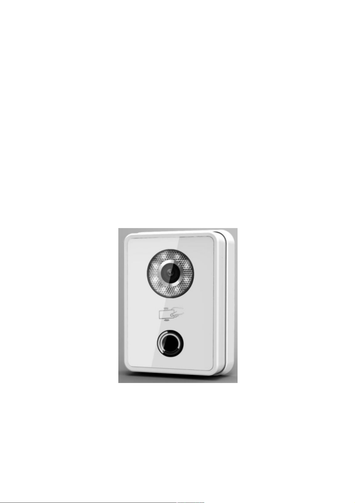
1
Product Appearance
Please wait about 10s for the indicators in touch button to turn on after you plug the
device to power supply. It takes about 60s for all the indicators to turn on and then off.
After the system boots up properly, you will see its front as shown in Figure 1- 1(black)
and Figure 1- 2 (white).
Figure 1- 1
Page 5
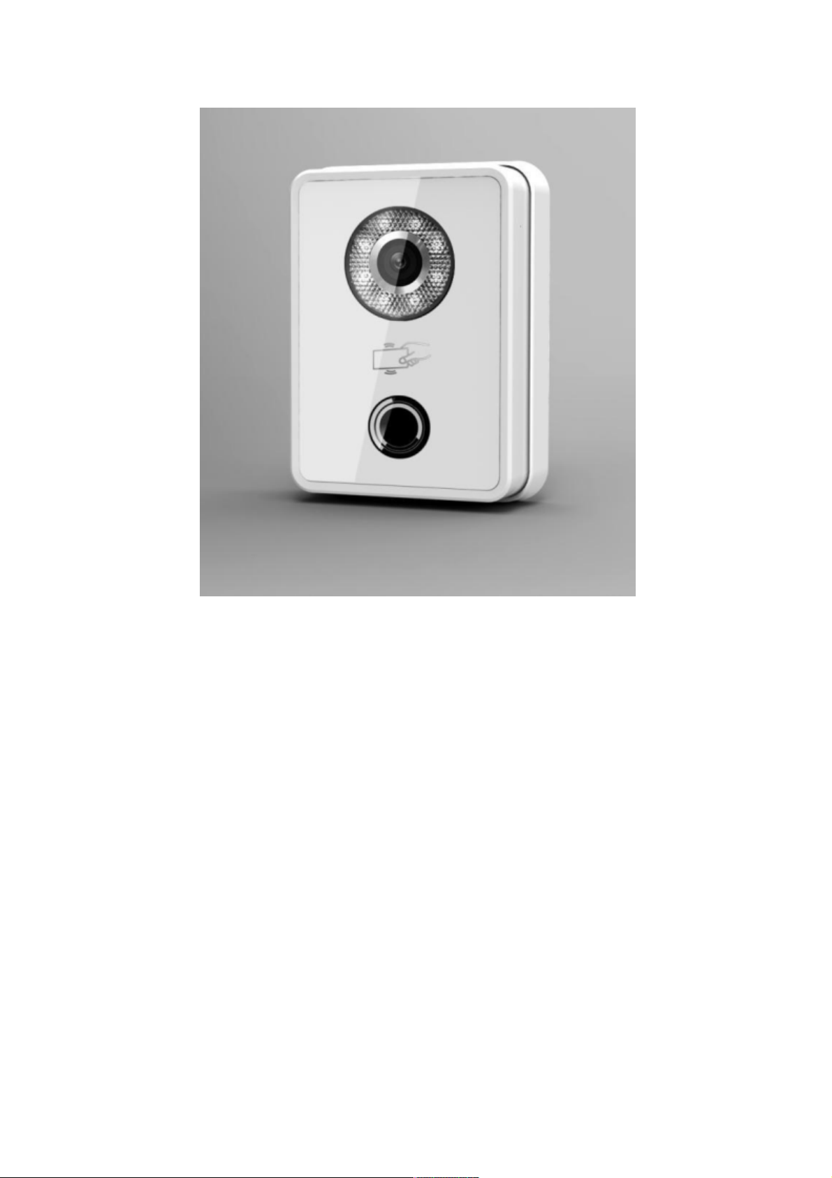
Figure 1- 2
VTO is a signature for indoor monitors.
VTH is a signature for outdoor stations.
VTS is a signature for a management center.
Page 6

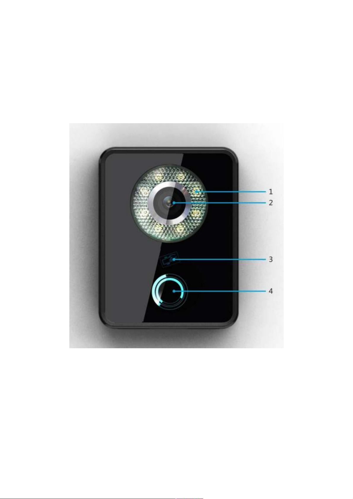
No. Name Function
1
Compensation
Light compensation will automatically
turn on during connecting status if there
is no enough light in environment.
2
3
4
Camera
It monitors corresponding door region.
Card Swiping Area You can swipe card in this area.
Touch Button
You can touch this button (the blue
indicator will be on) to call VTH or
manager center.
2
Basic Function Introduction
2.1 Call Manager Center
Within the time that allows you to call manager center, you can touch the button to
call manager center. Manager center’s time can be set on management platform or
VTO’s web-end. Once manager center picks up the call, you can perform a visual
bidirectional talk with the manager center. You can touch the button on VTO to end call at
any time.
2.2 Call User
2.2.1 Connecting Status
Within the time that allows you to call VTH, you can touch the button to call VTH.
Excluding time to call manager center, all remaining time supports call to VTH. During
connecting, you can touch the button on VTO to end call at any time.
2.2.2 Calling Status
Under connecting status, if the call is picked up, you will enter calling status. You can
perform a visual bidirectional talk with the VTH. During calling status, you can touch the
button on VTO to end call at any time.
2.3 Monitor
Both VTS and VTH are able to monitor this VTO by enabling the camera to capture
local circumstance.
Page 7
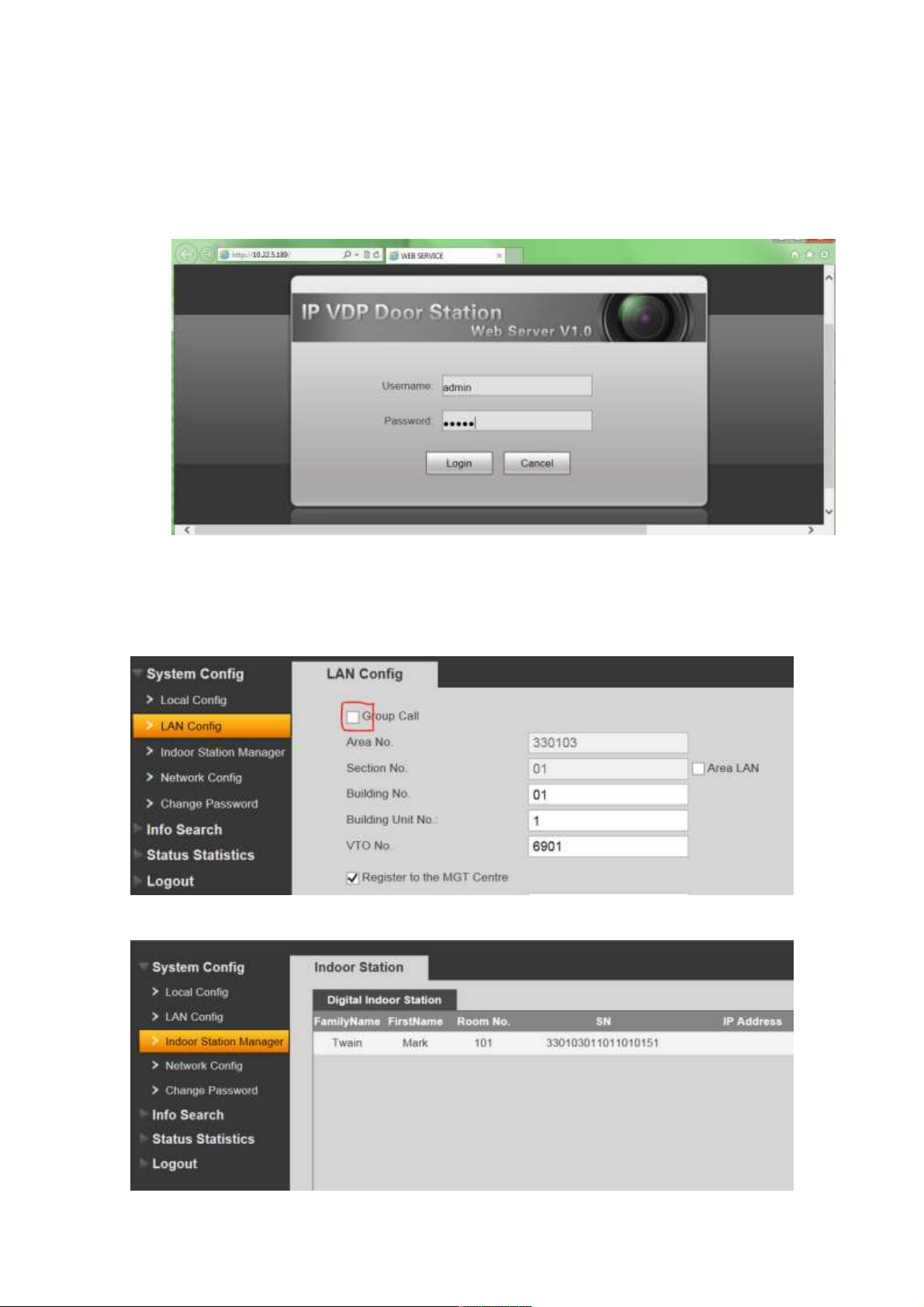
2.4 Web management
The door station has a web management for user-friendly settings. To go to the web
management open Internet Explorer web browser and go to 10.22.5.189 (default) IP
address. Default login is admin/admin.
2.5 Single Call
Go to the web management. Be sure Group Call is off.
In the Indoor staon manager input monitor data without IP address and reboot.
Page 8
Be sure PC -IP102ID is added in the monitor sengs well and is enabled there.
2.6 Group Call
If you want to call via one buon door staon more than one monitor at the same me,
you can use “group call” funcon. For group call you can´t connect every monitor models. This
funcon you can use only for combinaon of PM -Ip350 / PM -IP700TMD OR
PM -IP701TMD / PM -IP701TMD. There can be max. 6 monitors.
2.4.1. Settings for PM -Ip350/ PM -IP700TMD connection
The first (MASTER) monitor must be set to 101 adress and next monitors (SLAVES) must
be set to 199/198/197/196/195 adress. Eventually as on the table below:
2.4.2. Settings for PM -IP701TMD/ PM -IP702TMD connection
The first (MASTER) monitor must be set to 101 adress and next monitors (SLAVES) must
be set to Extension mode with 101-1/101-2/101-3/101-4/101-5 adress. Eventually as on the
table below:
Page 9

2.4.3. DPC-IP102ID web management settings
Page 10

Input master monitor data WITHOUT IP address and reboot.
Aer reboong open Indoor Staon Manager again to upload slave monitors sengs.
Page 11

2.7 Unlock
2.7.1 Unlock under Connecting Status (access control module required)
Under connecting status, VTS or VTH can remotely unlock door. VTO will return to
standby interface after call ends or countdown stops.
2.7.2 Unlock under Calling Status (access control module required)
Under calling status, VTS or VTH can remotely unlock door. VTO will return to
standby interface after call ends or countdown stops.
2.7.3 Unlock under Monitoring Status (access control module required)
Under monitoring status, VTS or VTH can remotely unlock door. VTO will return to
standby interface after call ends or countdown stops.
2.7.4 Unlock via IC Card (access control module required)
By swiping authorized IC card, you can unlock door after local verication.
2.8 Compensation of Light
In dark environment or at night, the VTO adopts auto photoreception technology
which achieves light compensation in connecting status.
2.9 Vandal Proof
There is one channel of vandal proof which will generate alarm sound and report to
the manager center once VTO is forced to leave the wall.
Page 12

3
Deeper introduction to Web
3.1 Login Interface
In Internet Explorer, input the IP address of VTO, a webpage pops up as in Figure 3-
1.
Figure 3- 1
Default username: admin
Default password: admin.
Click login to enter WEB interface.
The WEB cong interface consists of the following:
No. Name Function
1
System Cong
Here you can cong device
parameter and LAN info.
2 Info Search Here you can search call records.
3
Status Statistics
Here you can video VTH status
statistics.
4
Logout
Here you can reboot DPC-IP102ID and logout
WEB-end.
3.2 System Cong
System cong consist of: local cong, indoor station manager (VTH), LAN cong,
network cong and change password.
Page 13

3.2.1 Local Cong
Local Cong
Local cong includes issuing card, unlock and time setup. See Figure 3- 2.
Please note:
1) Frame rate: set 30 as frame rate for NTSC and 25 as frame rate for PAL standard.
2) Delete all: Click this button and then conrm. VTO will restore default settings. Be
cautious!
3) Video format: select WVGA. resolution: 800x480.
A&C Manager
A&C manager interface is shown in Figure 3- 3.
Figure 3- 2
Page 14

Figure 3- 3
Under local cong interface, click on A&C manager. The initial VTO password is
123456 and to unlock, input #123456#. Here you can change password, set unlock
responding interval and unlock period.
FTP IP: FTP IP is used in storing snapshot taken by the VTO while user can view
them by logging in this FTP IP.
Issue card: On web-end, click on issue card button and put the IC card on the card
swiping area. When you hear beep sound, you have successfully issued card. You can
use this new card to unlock door. (Access control module required)
System Time
System time interface is shown in Figure 3- 4.
Figure 3- 4
Under local cong interface, click on system time where you can set time and sync it
with PC.
Page 15

3.2.2 Indoor Station (VTH) Manager
Indoor station manager interface of VTO consists of add VTH, delete VTH and modify
VTH user.
Digital Indoor Station
Digital indoor station interface is shown in Figure 3- 5.
Figure 3- 5
Under digital indoor station interface, check display residence info enable to show
existing VTH info. Click add button at lower left, and input user info in the prompt box. In
default, only VTH short no. is mandatory.
3.2.3 LAN Cong
LAN cong interface is shown in Figure 3- 6.
Page 16

Figure 3- 6
Default cong is OK if you merely want to ensure the LAN connection between
VTO and VTH. If you want to cong manager center, the cong here must match info of
the manager center, and you need to check box of register to the MGT center.
Furthermore, if you would like to call manager center within congured period, you
have to set call VTS time. During this period, the VTO can only call VTS.
3.2.4 Network Cong
Network cong interface is shown in Figure 3- 7.
Figure 3- 7
Here you can set IP info of VTO which includes IP address, subnet mask and
default gateway. After you modied the IP address, the web interface will reboot and you
will be transferred to the new IP address.
Page 17

3.2.5 Change Password
Change password interface is shown in Figure 3- 8.
Figure 3- 8
Here you can change the web login password of VTO. You need to input old
password and new password and conrm new password. Click on OK to save.
3.3 Info Search
3.3.1 Call History
Call history interface is shown in Figure 3- 9.
Figure 3- 9
Under info search interface, click on call history. Here you can search call history of
the VTO with up to 1124 records.
Page 18

3.4 Status Statistics
3.4.1 VTH status
VTH status interface is shown in Figure 3- 10.
Under status statistics interface, click on VTH status. Here you can view connection
state of VTH.
Figure 3- 10
3.5 Logout
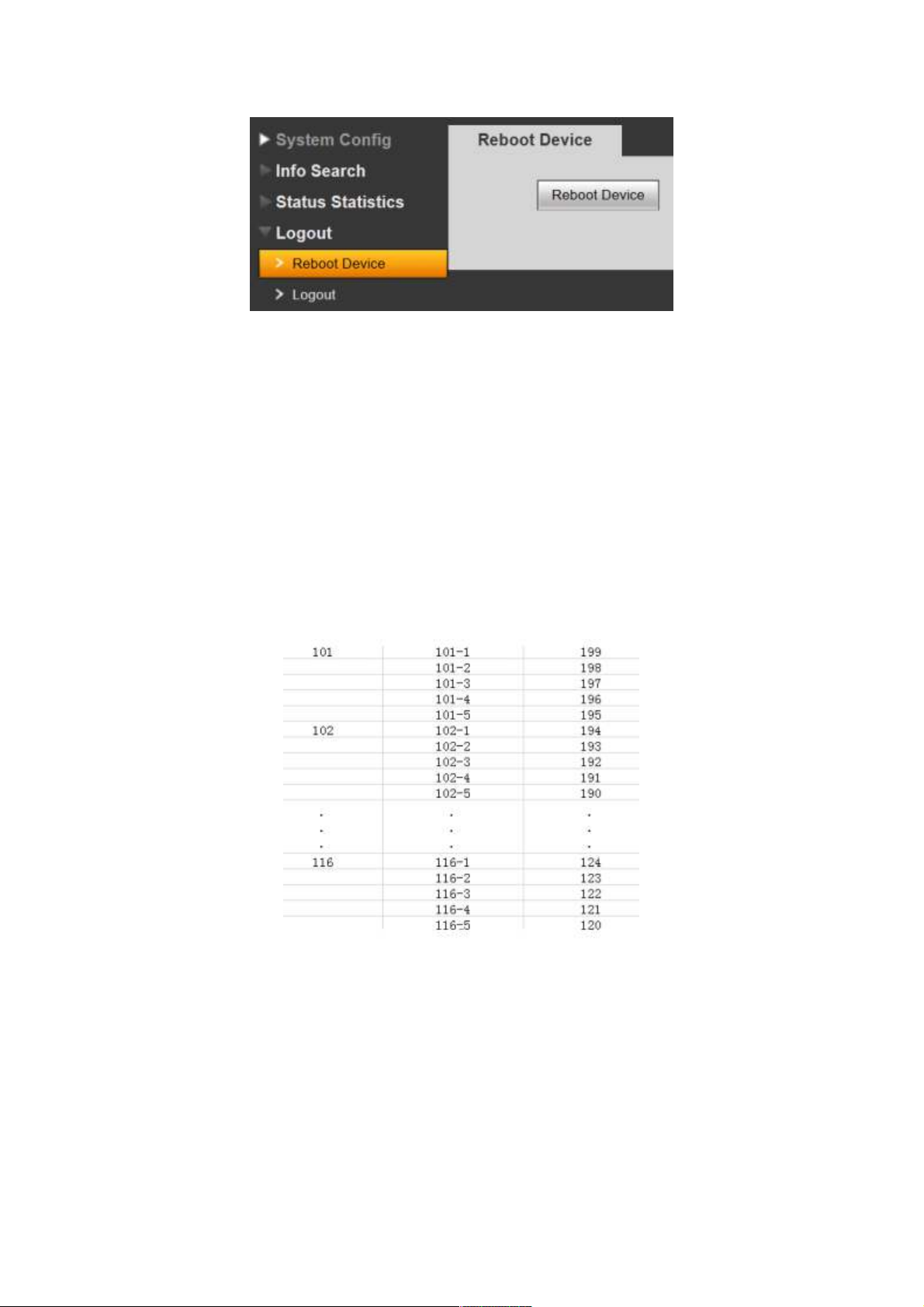
3.5.1 Reboot Device
Reboot device interface is shown in Figure 3- 11.
Here you can reboot the device.
3.5.2 Logout
Logout interface is shown in Figure 3- 12.
Figure 3- 11
Page 19

Here you can logout the device.
4
Technical Specifications
Model DPC-IP102ID
System
Main processor Embedded microcontroller
OS Embedded LINUX OS
Video
Video
compression
standard
Input/Approaching
Induction
Night vision Support
Audio
Input Omnidirectional microphone
Output Built-in loudspeaker
Bidirectional talk Support bidirectional talk
Operation Mode
Input One-key input(with backlight)
Swipe card Built-in IC card sensor
Alarm
Vandal proof Support
Network
Ethernet 10M/100Mbps self-adaptation
Internet protocol TCP/IP
Storage
Memory 128MB
General
Figure 3- 12
H.264
1.3 mega pixels CMOS HD camera
Page 20

Power supply DC 10~15V
Power
Standby ≤1W ;working ≤10W
consumption
Environment
Dimensions
-10℃~+60℃、10~95%RH
115mm*45mm*155mm(L*W*H)
Weight 0.5kg
5
Device Port Illustration
Ports of VTO are illustrated in Figure 5- 1.
No. Port Name Description
1
Vandal proof switch
2 Network port Connect to RJ45 port.
3
RS485
4 Power supply port Connect to 12V DC.
5 Loudspeaker output
Figure 5- 1
When this device is forced to leave
wall, it will generate alarm
sound and report to the
manager center.
May connect to external module,
such as access control extension
module.
It is the sound output of local
loudspeaker.
Page 21

NO
1
2
3
4
5
Port Name
Network port
Power supply port
Debug Port
Green Port 1 Connect Lock
Green Port 2
A) Lock and Unlock Button.
gure 6.
To connect Electric lock and unlock button to outdoor unit please see
Description
Connect to RJ45 port.
Connect to 12V DC.
Connect to magnetic feedback or
opening button
Figure
Page 22

6
1. As shown in gure connect one terminal of Electric Lock with “NO” and
next with “COM” on port 3 of outdoor unit.
2. As shown in gure connect unlock button one terminal with “ALM1” and
next terminal to “GND” on port 4 of outdoor unit.
B) Door Sensor.
To connect door sensor with outdoor unit see gure 7.
Figure 7
1. As shown in gure connect one terminal of door sensor with “NC” and next
with “COM” on port 3 of outdoor unit.
2. When Outdoor unit is connected to door sensor for its magnetic feedback,
connect magnetic feedback one terminal to “ALM 2” and connect next
terminal with “GND” on Port4 of outdoor unit.
6.
Installation Guide
Installation guide of VTO is illustrated in Figure 6- 1.
Page 23

Installation step:
1. Fix installation holder onto wall:
a) Use the M4 screw accompanied with the VTO to x holder onto the 86 box
4
(as ○
in Figure 6- 1);
b) In order to rm the VTO, use the ST4.0 screw accompanied with VTO to x
Figure 6- 1
the 86 box onto wall after locking the 86 box. (as ○
5
in Figure 6- 1);
2. Install ○2 in Figure 6- 1 onto the holder by pushing from top edge as ○
Figure 6- 1 to lower edge as ○
2
in Figure 6- 1.
3. After you complete the installation between VTO and holder, use the set screw
accompanied as ○
3
in Figure 6- 1 to fix the VTO and its holder.
1
in
Page 24

Installation step:
1. Fix installation holder onto wall:
Use the M4 screw accompanied with the VTO to x holder onto the 86 box (as
3)
2. B is to strengthen firmness of VTO, use the ST3.0 screw accompanied with VTO
to x the 86 box onto wall after locking the 86 box. (as c)
3. Install decoration cover (as 1) onto 2, secure with screw a.
Screw Illustration
No. Name Symbol
M3×8 cross recessed countersunk
head horizontal screw - galvanized
a
black
M4×30 cross recess head horizontal
b
screw
ST3×18 cross recess top
c
screw-nickel silver
Expansion pipe ¢6*30mm white
d
Page 25

7 FAQ
1. Q: How do I know if the power supply to VTO is working normally?
A: After you plug the device to power supply, wait about 10s for the indicators in touch
button to turn on. Approximately 60s later, all indicators will turn on as the device
works normally.
2. Q: You pressed the touch button, and the indicator turned on, but the VTO did not
start a call?
A: Please check your operation process.
3. Q: How to end a call when I am calling?
A: You can end a call by touching the button on VTO lightly.
4. Q: The device could not boot up and there was no sound or light.
A: Please check if power supply is well plugged.
5. Q: My call did not go though.
A: It is network connection error; please check the cables of the device and its
extension.
6. Q: The number I am calling does not exist.
A: Please check if the number is correct.
7. Q: VTO did not respond after I swiped IC card.
A: Please check if your card is authorized.
8. Q: I heard a beep sound when I swiped IC card, but the door did is still locked.
A: Please check if your card is authorized.
9. Q: I have other problems not included above.
A: Please contact technical staffs for assistance.
 Loading...