

Page 1
Click!
Click!
Accessories
MX-MT-v26-V/
MX-MT-v26-V-XL
Vandalism Set/
Vandalism Set for On-Wall
Set with Audio
*Variant Mx-v26B supports MOBOTIX MxBus modules
Mx-M-OWA-AU/
Mx-M-OWA-AU-b
On-Wall Set with Audio
for MxBus modules* and
signal inputs/outputs
Mx-A-IOA-IC
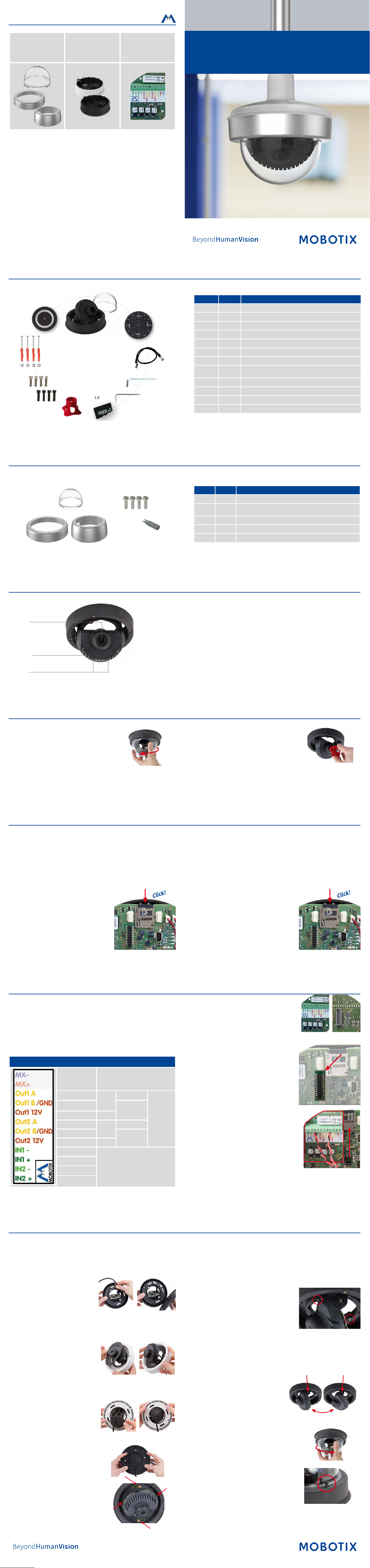
v26 Indoor Dome
Quick Install
Delivered Parts
1.12
1.11
1.10
1.9
1.8
1.1
1.7
1.6
1.5
1.2
1.4
1.3
Item Count Part Name
1.1 1
1.2 1
1.3 1 Ethernet patch cable, 50 cm/19.7 in, black
1.4 1
1.5 1
1.6 1
1.7 1
1.8 4
1.9 4
1.10 4
1.11 4
1.12 1
v26 with standard dome
Sealing
Allen wrench 2.5 mm
Torx wrench TX20
microSD card pre-installed (SDHC montiert, SDXC supported)
Lens wrench, red
Allen screws M4x16 mm, black (for black housing)
Allen screws M4x16 mm, silver-colored (for white housing)
Stainless steel washers Ø 5.3 mm
Dowels 8 mm
Stainless steel wood screws with Torx head 4.5x60 mm
Reection protection
32.860-003_EN_04/2018
Delivered Parts Vandalism Set/Vandalism Set for On-Wall Set with Audio
Except for the vandalism ring, the delivery of both sets is identical (items 2.1 and 2.1 a).
2.2
2.3
2.1
2.4
2.1 a
Item Count Part Name
2.1 1 Vandalism ring
2.1a 1
2.2 1 Vandalism dome, reinforced
2.3 4 Security screws
2.4 1 Screwdriver bit for security screws
Connecting the v26
You can nd detailed information on the installation and connections of the
Lens
Key
v26 in the Q25-Kamerahandbuch (PDF, available on www.mobotix.com >
Support > Download Center > Documentation > Manuals).
Regarding the initial operation of the v26, please see the D25 Camera
Manual in Chapter 3, «Initial Operation».
Use a suitable device for operating the camera key (e.g., a screw driver).
Vandalism ring
(Vandalism set for On-Wall set with audio)
LEDs
Installing the Lens
1. Remove the dome
Unscrew the dome by turning it counter-
clockwise).
Aer initial operation of the camera, remember to adjust the focus of the lens (see «Initial Operation» on page 2).
2. Install the lens
Using the red lens wrench, screw the lens into
the lens mount.
Inserting /Exchanging the SD Card
All camera models can use the integrated microSD card (SDXC) to record video data. In order to exchange the microSD card, please proceed as outlined
in the following instruction. For information on reliable SD cards, please see the MOBOTIX website www.mobotix.com > Support > Download Center >
Documentation > White Lists in the document microSD Card Whitelist for MOBOTIX Cameras.
When replacing the SD card, make sure that recording has been deactivated in the browser (Admin Menu > Storage > Storage on External File Server /
Flash Device; activate recording again in the same dialog). To get to the back of the main board, you may have to loosen the screws at the le and right
side of the main board support, and tilt the main board support slightly forward (see «Installing the v26», Step 7).
1. Remove the SD card
If a microSD card has been installed, gently
press with your nger as indicated by the arrow
until you hear a click. Then release the SD
card. The card is protruding slightly and can
2. Insert the SD card
Insert the microSD card and gently press with
your nger as indicated by the arrow until you
hear another click.
Make sure that the SD card is fully inserted.
be easily removed.
Installing the Mx-A-IOA-IC
For the Mx-v26A/B, you can use the optionally available Mx-A-IOA-IC to attach external sensors using the signal inputs and
to switch other devices via the signal outputs. When used with the the Mx-v26B, you can also attach MxBus devices (e.g., an
MX-GPS-Box). To attach the Mx-A-IOA-IC Module, you need to remove the dome, You may also have to loosen the screws at the
le and right side of the main board support, and tilt the main board slightly forward (see «Installing the v26» step 7).
1. Attach the connection cables
Attach the connection cables as shown in the terminal connector overview.
Terminal Connectors
MxBus connectors
Output 1 A
Output 1 B/GND
Output 1 12 V –
Output 2 A
Output 2 B/GND
Output 2 12 V –
Input 1 –
Input 1 +
Input 2 –
Input 2 +
MxBus functionality is only supported
by the camera variant Mx-v26B.
Relay
pot.-
free
Relay
pot.-
free
–
Output 1
12 V
–
Output 2
12 V
Inputs
Outputs
2. Insert the Mx-A-IOA-IC
Hold the Mx-A-IOA-IC over the receptacle on
the main board (red arrow in gure). Make
sure that the green terminal connector block
is pointing upward (towards the SD card, see
red arrow in gure).
Use one nger to carefully press the board of
the module onto the receptacle. Make sure that
the Mx-A-IOA-IC is fully inserted.
Installing the v26
Use the drilling template on the back for this step. Mark the holes for dowels or screws If required, drill the holes for the dowels, push them in and attach
the v26 with dowels and screws.
1. Connect the cables
Guide the cables (network cable, USB
cable, MxBus wires and signal input/
output wires) through the cut-out in the
sealing. When doing this, make sure that
you do not damage the cables/wires.
Connect the cables/wires to the v26.
2. Mount the reection protection
To avoid reections within the interior
of the white housing, you should apply
the supplied reection protection (two
pieces, item 1.12). In the black housing,
the protection also covers the silver-colored screws. Place the ring around the
main board support. Press the ring into
the recess of the housing. Turn the housing on its back.
Now take the disc and pull it gently
apart at the cut. Place the disc around
the cables where the sealing and the
housing meet. Push the disc down on
the opening in the housing.
3. Place sealing on v26
Place the sealing on the back of the
v26 as shown.
4. Install the v26
Press the camera and the wall sealing
against the ceiling and align the holes
with the holes for the dowels/screws.
You may have to loosen the fastening
screws (see below) and rotate the main board support to get to these
screws. Insert the screws with washers and tighten them.
5. Adjust viewing direction
Release the fastening screws and rotate the
camera into the desired viewing direction.
Tighten the screws (torque 0,4 Nm) again
once you are nished.
6. Start the camera and focus the lens
For the rst start of the camera and for adjusting the focus of the lens, see
«Initial Operation» on page 2.
7. Set the tilt angle of the lens
Make sure that the lens is tilted properly.
If this is not the case, loosen the screws
to the right and le of the mainboard
support and tilt the camera. Tighten
the screws again once you are nished.
8. Install the dome
Mount the dome. If you are using the vandalism
set, install the reinforced vandalism dome instead.
9. Close the screw holes
If you do not use the vandalism set, you should
close o the four holes using the supplied black
or silver screws, depending on the color of
the set.
Page 2
§
§
70 mm/2.76 in
70 mm/2.76 in
Installing the v26 (continued)
Exit 1
Exit 2
10. Install the stainless steel ring of the vandalism set
Vandalism set: When using the vandalism set,
attach the stainless steel ring with the security
screws (torque 0,4 Nm) and use the supplied
screwdriver bit to rmly tighten the screws.
Vandalism set for On-Wall set with audio:
For installing and mounting, please follow the instructions as described in
Install: Audio On-Wall Set
(www.mobotix.
Quick
com > Support > Download Center).
Attach the stainless steel ring with the security
screws. Make sure that the cutout in the stain-
less steel ring tightly ts around the cable tting of the On-Wall set. Use
the supplied screwdriver bit to rmly tighten the screws (torque 0,4 Nm).
Initial Operation
The initial operation starts with connecting the power supply (see section «Network and Power Connection, Additional Cables» in the D25 Camera Manual).
The rst access follows the procedure described in the same manual in the section «Initial Operation of the Camera». All other tasks require access to the
camera's user interface in the browser. Enter the camera’s IP address into the address bar of the browser (user "admin", password "meinsm"; password
must be changed upon rst login – camera soware V5.1.x and higher).
1. Set the lens
Open the Admin Menu > Hardware Congura-
tion > Lens Conguration dialog and select the
installed lens. This step is required to select the
proper special functions of the installed lens (e.g.,
for wide-angle lenses).
2. Adjust the lens focus
Remove the dome before proceeding.
Check the live image from the camera in the browser. Activate the focusing
aid in the browser (Focusing Aid quick control, Activated value).
Carefully turn the lens using the red lens wrench in clockwise or counter-clockwise direction until the red area of the
focusing aid in the camera image is as small as
possible.
Once the focus is adjusted properly, deactivate
the focusing aid again (Focusing Aid quick control, Disabled value).
Note: Due to the lens eect of the dome, the focus of the B237 tele lens
is shiing slightly once the dome has been mounted. Before mounting
the dome, the tele lens should be turned about 90° in counter-clockwise
direction (as seen from the lens' front). Make sure that you check the focus
of the live image in your browser with the dome installed and re-adjust
the lens, if required.
3. Congure and use the Mx-A-IOA-IC
Aer starting the camera with installed Mx-A-IOA-IC,
the module is recognized automatically and listed
in the Camera Status browser dialog in the Sys-
tem section.
You can immediately use the signal inputs to
dene signal event proles in Setup Menu > Event
Overview. Likewise, you can immediately use the
signal outputs to dene signal output proles in
Admin Menu > Hardware Conguration > Signal
Out Proles.
In addition, the signal inputs and outputs are automatically listed in the
Admin Menu > Assign Wires dialog so you can use them immediately for
door and light features.
If you want to use one or both signal outputs not as potential-free outputs,
but as 12 V outputs, open the Admin Menu > Hardware Conguration >
Manage Hardware Expansions dialog. In the/IO Board section, click on
Connect for each output you want to use as a self-powered 12 V output.
4. Save the conguration
In the live image of the browser, select the Manage Settings quick control
and set Store Entire Conguration as value. The camera stores the con-
guration in the permanent camera memory so that the settings will be
applied at the next camera reboot
Boot Options of the v26
By default, the camera starts as DHCP client and automatically tries to get
an IP address from a DHCP server. To start the camera in a mode dierent
from the default mode, you can activate the boot menu of the camera.
1. Preparing the Camera
• Remove the outer shell and the dome.
• Disconnect the camera's power supply.
• Reconnect the power supply of the camera.
2. Activating the Boot Menu
The red LED lights up 5 to 10 seconds aer establishing the power supply and will stay on for
10 seconds. Briey press th key indicated by
the red circle in the gure. The camera enters
the boot menu, ready for selecting one of the
boot options. To operate the camera key, use a suitable device (e.g., a
screw driver).
The LED now ashes once and repeats the ash signal aer pausing for
one second (the number of ashes indicates the current boot option). To
go to the next boot option, briey press the key again (< 1 sec). Aer the
last boot option, the camera returns to the rst option (LED ashes once).
LED
ashes
*Only on cameras with audio option and installed speaker.
1 x
2 x
3 x
4 x
Boot
Option
—
Factory
Defaults
Automatic
IP Address
Recovery
System
Meaning
This option is not used on this camera
model.
Starts the camera with factory defaults
(factory default IP address, users and
passwords will not be reset).
Starts the camera as DHCP client and
tries to obtain an IP address from a DHCP
server. If a DHCP server cannot be found
or no IP address can be obtained, the
camera starts with its factory default
address.
Starts the camera with the recovery system, e.g., in order to recover from a failed
update of the camera soware.
Audio
Conrmation*
—
Boing
Boing Boing
Alarm Sound
3. Selecting a Boot Option
Press the key longer (> 2 sec). The camera conrms the selection by ashing
rapidly three times. Aer 20 sec, the camera will conrm the selection by
playing a sound according to the table above. If nothing is selected, the
camera will resume its normal boot process aer a certain time.
The outer shell and the dome can be mounted again.
Important Notes
Safety Warnings
Notes on Installing:
• This product must not be used in locations exposed to
the dangers of explosion.
•
Make sure that you install this product as outlined in the instructions
of this Quick Install document. A faulty installation can damage the
camera!
• When installing this product, make sure that you are only using genuine MOBOTIX parts and MOBOTIX connection cables.
• Only install this product on suitable, solid materials that provide for
a sturdy installation of the xing elements used.
Electrical installation: Electrical systems and equipment may
only be installed, modied and maintained by a qualied
electrician or under the direction and supervision of a quali-
ed electrician in accordance with the applicable electrical guidelines.
Make sure to properly set up all electrical connections.
Electrical surges: MOBOTIX cameras are protected against
the eects of small electrical surges by numerous measures.
These measures, however, cannot prevent the camera from
being damaged when stronger electrical surges occur. Special care should
be taken when installing the camera outside of buildings to ensure proper
protection against lightning, since this also protects the building and the
whole network infrastructure.
Max. power consumption of attached extension modules:
The power consumption of all attached MxBus modules must
not exceed 2,5 W. When attaching modules to the MxBus
connector and the USB socket, the power consumption of all attached
modules must not exceed 3 W, if the camera is powered by PoE class 3.
If PoE class 2 is used, the power consumption of all attached modules
must not exceed 1 W!
Never touch the lens: Due to the high performance of the v26,
the area of the image sensor can get quite hot, especially
when the ambient temperature is also high. This does not
aect the proper functioning of the camera in any way. For this reason,
the product must not be installed within the reach of persons.
Power o before opening the camera: Make sure the power
supply to the camera is disconnected before opening the
camera housing (e.g., when exchanging the SD card or when
opening the body to attach wires).
Network security: MOBOTIX products include all of the necessary conguration options for operation in Ethernet networks in compliance with data protection laws. The operator
is responsible for the data protection concept across the entire system.
The basic settings required to prevent misuse can be congured in the
soware and are password-protected. This prevents unauthorized parties
from accessing these settings.
Legal Notes
Legal aspects of video and sound recording: You must comply with all data protection regulations for video and sound
monitoring when using MOBOTIX products. Depending on
national laws and the installation location of the v26, the recording of
video and sound data may be subject to special documentation or it may
be prohibited. All users of MOBOTIX products are therefore required to
familiarize themselves with all applicable regulations and to comply with
these laws. MOBOTIX AG is not liable for any illegal use of its products.
Disposal
Electrical and electronic products contain many valuable
materials. For this reason, we recommend that you dispose of
MOBOTIX products at the end of their service life in accordance
with all legal requirements and regulations (or deposit these
products at a municipal collection center). MOBOTIX products must not be
disposed of in household waste! If the product contains a battery, please
dispose of the battery separately (the corresponding product manuals
contain specic directions if the product contains a battery).
Disclaimer
MOBOTIX AG does not assume any responsibility for damages,
which are the result of improper use or failure to comply to the
manuals or the applicable rules and regulations. Our General
Terms and Conditions apply. You can download the current version of the
General Terms and Conditions from our website at www.mobotix.com
by clicking on the COS link at the bottom of every page.
Technical Specications
Mx-v26A/B*-6Dxxx (daylight image sensor, color)
Mx-v26A/B*-6Nxxx (night image sensor, Black&White)
Model Variants
Lens Options B036 – B237 (103° to 15° horizontal angle of view)
Sensitivity
Image Sensor 1/1,8“ CMOS, 6MP (3072x2048), progressive scan
Max. Image Size 6MP (3072x2048)
Image Formats
Max. Frame Rate
Video Codec
ONVIF ONVIF-S (camera soware V5.0.2.x and higher)
DVR
Mx-v26A/B*-AU-6Dxxx (audio package, daylight image sensor, color)
Mx-v26A/B*-AU-6Nxxx (audio package, night image sensor,
Black&White)
*Variant Mx-v26B supports MOBOTIX MxBus modules
Color sensor (day): 0,1 lx @ 1/60s; 0,005 lx @ 1s
BW sensor (night): 0,02 lx @ 1/60s; 0,001 lx @ 1s
Freely congurable format 4:3, 8:3, 16:9 or costumized format (image
cropping), e.g., 2592x1944 (5MP), 2048x1536 (QXGA), 1920x1080
(Full-HD), 1280x960 (MEGA)
MxPEG (max.): 42@HD (1280x720), 34@Full-HD, 24@QXGA, 15@5MP,
12@6MP
M-JPEG (max.): 26@HD (1280x720), 13@Full-HD, 9@QXGA, 5@5MP,
4@6MP
H.264 (max.): 25@Full-HD, 20@QXGA
MxPEG, M-JPEG, JPEG (max. output format 6MP)
H.264 (max. output format QXGA; bandwidth limitation possible)
On internal microSD card (SDHC installed, SDXC supported)
External on USB device
External on NAS
Full image recording regardless of live image zoom
MxFFS
Pre-alarm and post-alarm images
DVR monitoring with error notication
Soware MxManagementCenter
Image Processing
PTZ Digital pan/tilt/zoom; max. zoom 8x (continuous)
Alarm/Events
Intelligent Video Analysis MxActivitySensor, video motion analysis, MxAnalytics
Audio None, expandable with, for example, On-Wall set with audio
Interfaces
Security
Certications
Power Supply Power over Ethernet IEEE 802.3af
Power Consumptions Typ. 4 W
Power Consumption of
External Devices
Protection Classes
Ambient Temperature 0 to 40 °C/32 to 104 °F
Dimensions/Weight
Housing PBT-30GF, white and black
MxLEO, backlight compensation, automatic white balance,
image distortion correction
Temperature sensor, shock detector (with rmware version 5.0.1 and
higher), other sensors/IOs via MxMessageSystem, notication via
email, FTP, VoIP, SIP
Ethernet 100Base-T (MxRJ45), MiniUSB (MxMiniUSB), MxBus*
*Only variant Mx-v26B
User/group management, HTTPS/SSL, IP address lter, IEEE 802.1x,
intrusion detection, digital image signature, MxFFS
EN55032:2012; EN55022:2010; EN55024:2010; EN50121-4:2015;
EN61000-6-1:2007; EN 61000-6-2:2005 EN61000-6-3:2007+A1:2011;
EN61000-6-4:2007 +A1:2011;
AS/ NZS CISPR22:2009+A1:2010;
CFR47 FCC part15B
At MxBus: max. 2,5 W, at USB: max. 2.5 W, total max. 3 W
The power consumption of the camera will increase accordingly!
IP protection class: IP20
IK protection class: IK10 without accessories, IK08 with On-Wall set
with audio, IK10+ with Vandalism set
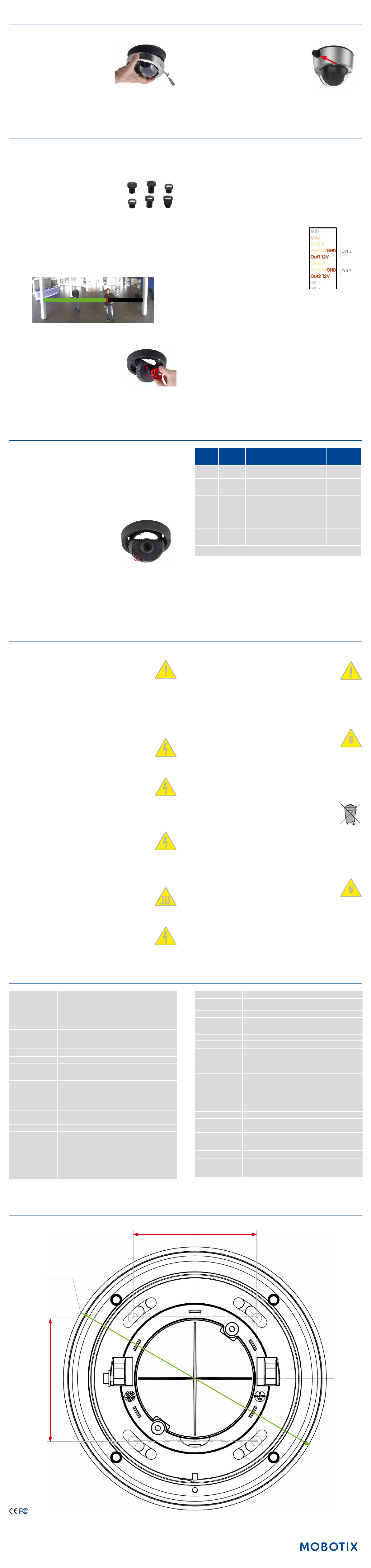
Height x diameter: 90 x 150 mm/3.54 x 5.90 in;
weight: approx. 380 g
Drilling Template
Ø 149 mm/5.87 in
Further information on www.mobotix.com:
• Products > Indoor Cameras > v26 Indoor Dome
• Support > Download Center > Documentation > Certicates & Declarations of Conformity
MOBOTIX, the MX logo, MxPEG and MxActivitySensor sare trademarks of MOBOTIX AG registered in the Euro-
pean Union, the U.S.A., and other countries • Information subject to change without notice • MOBOTIX does
not assume any liability for technical or editorial errors or omissions contained herein • All rights reserved •
© MOBOTIX AG 2017
 Loading...